


Hino 238, 258LP, 268, 338, 358 Workshop Manual
MENU
FOREWORD
This workshop manual has been prepared to provide information regarding repair procedures on Hino Trucks.
Applicable for HINO 238, 258LP, 268, 338 series, equipped with J08E-VB and J08E-VC engine
When making any repairs on your vehicle, be careful not to be injured through improper procedures.
As for maintenance items, refer to the Driver’s / Owner
All information and specifications in this manual are based upon the latest product information available at the time of printing.
Hino Motors Sales U.S.A., Inc. reserves the right to make changes at any time without prior notice.
Please note that the publications below have also been prepared as relevant workshop manuals for the components and
systems in these vehicles.
Manual Name Pub. No.
Chassis Workshop Manual
J08E-VB, VC Engine Workshop Manual S5-UJ08E10A
Trouble Shooting Workshop Manual
's Manual.
S1-UNAE10A 1/2
S1-UNAE10A 2/2
S7-UNAE10C 1/4
S7-UNAE10C 3/4
S7-UNAE10C 4/4

CHAPTER REFERENCES REGARDING THIS WORKSHOP MANUAL
Use this chart to the appropriate chapter numbers for servicing your particular vehicle.
MANUAL NO. S7-UNAE10C 2/4 (U.S.A.), S7-CNAE10C 2/4 (CANADA)
CHAPTER
GENERAL INTRODUCTION 1-001
TROUBLE SHOOTING - COMPONENTS 2-001
TROUBLE SHOOTING ELECTRICAL CONTROL SYSTEM
ENGINE CONTROL SYSTEM (J08E) 4-001
DEF SCR SYSTEM (DCU) 5-001
BURNER CONTROL SYSTEM (BCU) 6-001
BRAKE CONTROL SYSTEM
VEHICLE CONTROL SYSTEM (VCS) 11-001
CAN COMMUNICATION 12-001
DX MANUAL DX01-001 DX02-001 DX03-001 DX04-001 DX06-001 DX07-001
This manual does not contain items on half-tone dot meshing.
MODELS HINO 238, 258LP, 268, 338, 358
Production Code NE8J, NF8J, NJ8J, NV8J
3-001
9-001
(ABS:HYDRAULIC (E VERSION))
(ABS:FULL AIR)
9-002

INDEX: TROUBLE SHOOTING
GENERAL INTRODUCTION
TROUBLE SHOOTING - COMPONENTS
TROUBLE SHOOTING ELECTRICAL CONTROL SYSTEM
WORKSHOP
MANUAL
ENGINE CONTROL SYSTEM (J08E)
DEF SCR SYSTEM (DCU)
BURNER CONTROL SYSTEM (BCU)
BRAKE CONTROL SYSTEM
VEHICLE CONTROL SYSTEM (VCS)
CAN COMMUNICATION

ENGINE CONTROL SYSTEM (J08E) 4–1
ENGINE CONTROL SYSTEM (J08E)
4
ENGINE CONTROL SYSTEM......................................4-3
PRECAUTIONS FOR DIAGNOSIS.........................4-3
SYSTEM BLOCK DIAGRAM...................................4-5
SYSTEM DIAGRAM................................................4-6
PRECAUTIONS ......................................................4-8
SENSOR LOCATION ............................................4-11
COMPUTER (ECU) PIN ASSIGNMENT............... 4-20
ENGINE ECU CONNECTOR................................4-24
INSPECTION ........................................................ 4-28
DIAGNOSIS USING THE PC DIAGNOSIS
TOOL.....................................................................4-29
DIAGNOSTIC TROUBLE CODE (DTC)
TABLE ...................................................................4-30
GROUP SHARING THE SENSOR POWER SUPPLY
TERMINAL ............................................................4-45
GROUP SHARING THE SENSOR GND
TERMINAL ............................................................4-46
ENGINE BASIC INSPECTION SHEET
(ENGINE INSPECTION CHECK SHEET) ............4-47
NO DTC ................................................................4-50
DTC: P0016 ..........................................................4-53
DTC: P003A ..........................................................4-57
DTC: P0045 ..........................................................4-64
DTC: P0047 ..........................................................4-71
DTC: P0048 ..........................................................4-78
DTC: P006E ..........................................................4-85
DTC: P006F ..........................................................4-90
DTC: P007B ..........................................................4-95
DTC: P007C and P007D.....................................4-113
DTC: P0088 ........................................................4-122
DTC: P0096 ........................................................4-146
DTC: P0097 and P0098 ......................................4-161
DTC: P00AF........................................................4-170
DTC: P0101 ........................................................4-175
DTC: P0104 ........................................................4-187
DTC: P0106 ........................................................4-195
DTC: P0108 ........................................................4-202
DTC: P0112 and P0113 ......................................4-210
DTC: P0115 ........................................................4-219
DTC: P0117 and P0118 ......................................4-231
DTC: P011A ........................................................4-241
DTC: P011C........................................................4-252
DTC: P0122 and P0123 ......................................4-260
DTC: P0128 ........................................................4-273
DTC: P016E and P016F .....................................4-280
DTC: P0182 and P0183 ......................................4-304
4-001
DTC: P0191 ........................................................4-313
DTC: P0192 and P0193 ......................................4-335
DTC: P01A5 ........................................................4-346
DTC: P01A6 ........................................................4-355
DTC: P0200 ........................................................4-364
DTC: P0201, P0202, P0203, P0204, P0205 and
P0206..................................................................4-367
DTC: P0217 ........................................................4-376
DTC: P0219 ........................................................4-383
DTC: P0222 and P0223 ......................................4-390
DTC: P0234 ........................................................4-402
DTC: P0237 ........................................................4-409
DTC: P0263, P0266, P0269, P0272, P0275 and
P0278..................................................................4-418
DTC: P026C and P026D.....................................4-434
DTC: P0299 ........................................................4-452
DTC: P0300 ........................................................4-459
DTC: P0301, P0302, P0303, P0304, P0305 and
P0306..................................................................4-469
DTC: P0335 ........................................................4-481
DTC: P0336 ........................................................4-489
DTC: P0340 ........................................................4-497
DTC: P0341 ........................................................4-504
DTC: P0381 ........................................................4-512
DTC: P0401 ........................................................4-519
DTC: P0402 ........................................................4-537
DTC: P0404 ........................................................4-550
DTC: P0405 and P0406 ......................................4-557
DTC: P041B ........................................................4-564
DTC: P041C and P041D.....................................4-579
DTC: P0420 ........................................................4-589
DTC: P0489 and P0490 ......................................4-596
DTC: P049D........................................................4-603
DTC: P04D5 and P04D6.....................................4-610
DTC: P0500 and P0501 ......................................4-619
DTC: P0504 ........................................................4-627
DTC: P0519 ........................................................4-635
DTC: P0524 ........................................................4-639
DTC: P0562 and P0563 ......................................4-646
DTC: P05F1 ........................................................4-654
DTC: P0605 ........................................................4-664
DTC: P0606 ........................................................4-667
DTC: P0607 ........................................................4-670
DTC: P0610 ........................................................4-673
DTC: P0611 ........................................................4-677
DTC: P0617 ........................................................4-680

ENGINE CONTROL SYSTEM (J08E)4–2
DTC: P0628 and P0629 ......................................4-685
DTC: P062F ........................................................4-694
DTC: P0630.........................................................4-699
DTC: P0642.........................................................4-703
DTC: P0643.........................................................4-710
DTC: P064C ........................................................4-718
DTC: P0652.........................................................4-725
DTC: P0653.........................................................4-731
DTC: P0671, P0672, P0675 and P0676 .............4-738
DTC: P0683.........................................................4-750
DTC: P0686.........................................................4-757
DTC: P06D3 and P06D4 .....................................4-762
DTC: P0704.........................................................4-770
DTC: P073D ........................................................4-776
DTC: P081A ........................................................4-783
DTC: P081B ........................................................4-788
DTC: P0850.........................................................4-793
DTC: P1133.........................................................4-800
DTC: P119F ........................................................4-808
DTC: P141F ........................................................4-815
DTC: P1426.........................................................4-818
DTC: P1427.........................................................4-826
DTC: P1428.........................................................4-834
DTC: P1458.........................................................4-843
DTC: P1459.........................................................4-850
DTC: P14B0 ........................................................4-857
DTC: P14B2 ........................................................4-862
DTC: P14B3 and P14B4 .....................................4-867
DTC: P14B7 and P14B8 .....................................4-874
DTC: P14BC and P14BD ....................................4-881
DTC: P14BF ........................................................4-888
DTC: P1515.........................................................4-895
DTC: P1530.........................................................4-901
DTC: P1601.........................................................4-906
DTC: P200C ........................................................4-911
DTC: P203F ........................................................4-922
DTC: P204F ........................................................4-927
DTC: P207F ........................................................4-931
DTC: P20EE........................................................4-943
DTC: P2100.........................................................4-955
DTC: P2101.........................................................4-962
DTC: P2103.........................................................4-970
DTC: P2120.........................................................4-977
DTC: P2122 and P2123 ......................................4-982
DTC: P2127 and P2128 ......................................4-991
DTC: P2135.......................................................4-1002
DTC: P2138.......................................................4-1009
DTC: P2146.......................................................4-1015
DTC: P2147 and P2148 ....................................4-1023
DTC: P2149.......................................................4-1032
DTC: P2150 and P2151 ....................................4-1040
DTC: P2184 and P2185 ....................................4-1049
DTC: P2214.......................................................4-1058
DTC: P2227.......................................................4-1072
DTC: P2228 and P2229 ....................................4-1077
DTC: P2269.......................................................4-1082
DTC: P226C ......................................................4-1088
DTC: P22D3 ......................................................4-1097
DTC: P240F ......................................................4-1102
DTC: P242B ......................................................4-1115
DTC: P242C and P242D ...................................4-1125
DTC: P244A ......................................................4-1135
DTC: P244B ......................................................4-1161
DTC: P2457.......................................................4-1190
DTC: P2459.......................................................4-1207
DTC: P2463.......................................................4-1210
DTC: P246F ......................................................4-1224
DTC: P2470 and P2471 ....................................4-1234
DTC: P2563.......................................................4-1244
DTC: P2564 and P2565 ....................................4-1251
DTC: P259E ......................................................4-1260
DTC: P259F ......................................................4-1267
DTC: P2635.......................................................4-1274
DTC: P268A and P2696....................................4-1296
DTC: P2BA9......................................................4-1303
DTC: U0073 ......................................................4-1309
DTC: U010A ......................................................4-1313
DTC: U010C......................................................4-1316
DTC: U010E ......................................................4-1319
DTC: U029D......................................................4-1322
DTC: U029E ......................................................4-1325
DTC: U02A2 ......................................................4-1328
DTC: U0301 ......................................................4-1331
DTC: U1001 ......................................................4-1335
DTC: U110A ......................................................4-1338
DTC: U111E ......................................................4-1341
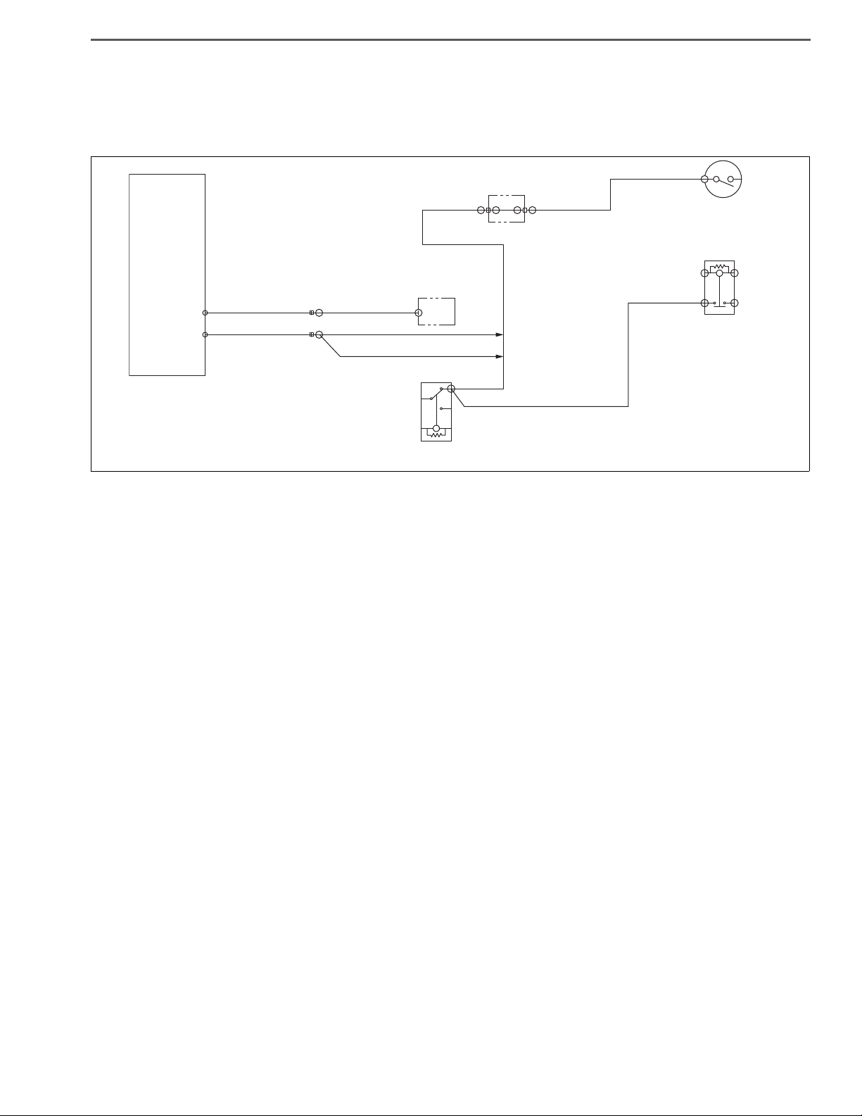
ENGINE CONTROL SYSTEM (J08E) 4–783
%L9
(STA)
K01
(S+)
K04
(NC)
NK0
(NO)
(ST)
N6E
(CL2-)
%L7
(STA)
ATM starter relay
Starter cut relay
Starter cut relay
LL1K01
K0G%D7
K0G
(STCR)
LL1
Engine
ECU
SAPH16F010300632
DTC: P081A
P081A: Starter Disable Circuit Low
INFORMATION
EN01H16F01030F03001098
1. Technical description
• The starter cut relay prevents further rotations of the starter when the starter switch is turned after start of the engine.
<Description of malfunction>
• Harness GND short-circuit or disconnection and relay unit failure are detected.
2. DTC set condition
(1) Check conditions
• Engine speed of 500 r/min or more. (Request starter cut relay operation)
• Starter switch ON.
• Battery voltage is in the range of 10 V to 16 V.
The conditions described above remain for 5 seconds or longer.
(2) Judgement criteria
• Output of the starter cut relay remains at 10 V or less for 3 seconds or longer.
3. Reset condition
• Just after restoration to normal condition.
4. Indication, warning or system control regulation when the DTC is set.
• MIL: OFF
• Diag lamp: OFF
5. Symptoms on the vehicle when the DTC is set
<Symptoms on the vehicle due to backup control (fail safe function)>
• –
<Symptoms on the vehicle due to malfunction>
• Starter operates even when the engine is running.
6. Pre-inspection work
• Check that the battery voltage is in the normal range.

ENGINE CONTROL SYSTEM (J08E)4–784
7. After-inspection work
• Clear all past DTCs.
• Check that no DTC is stored after test drive.
8. Estimated failure factors
• Harness disconnection or short-circuit
• Looseness or poor contact of connector
• starter cut relay failure
• Engine ECU failure

ENGINE CONTROL SYSTEM (J08E) 4–785
NOYES
NOYES
Select
Engine
SAPH16F010300633
INSPECTION PROCEDURE: P081A
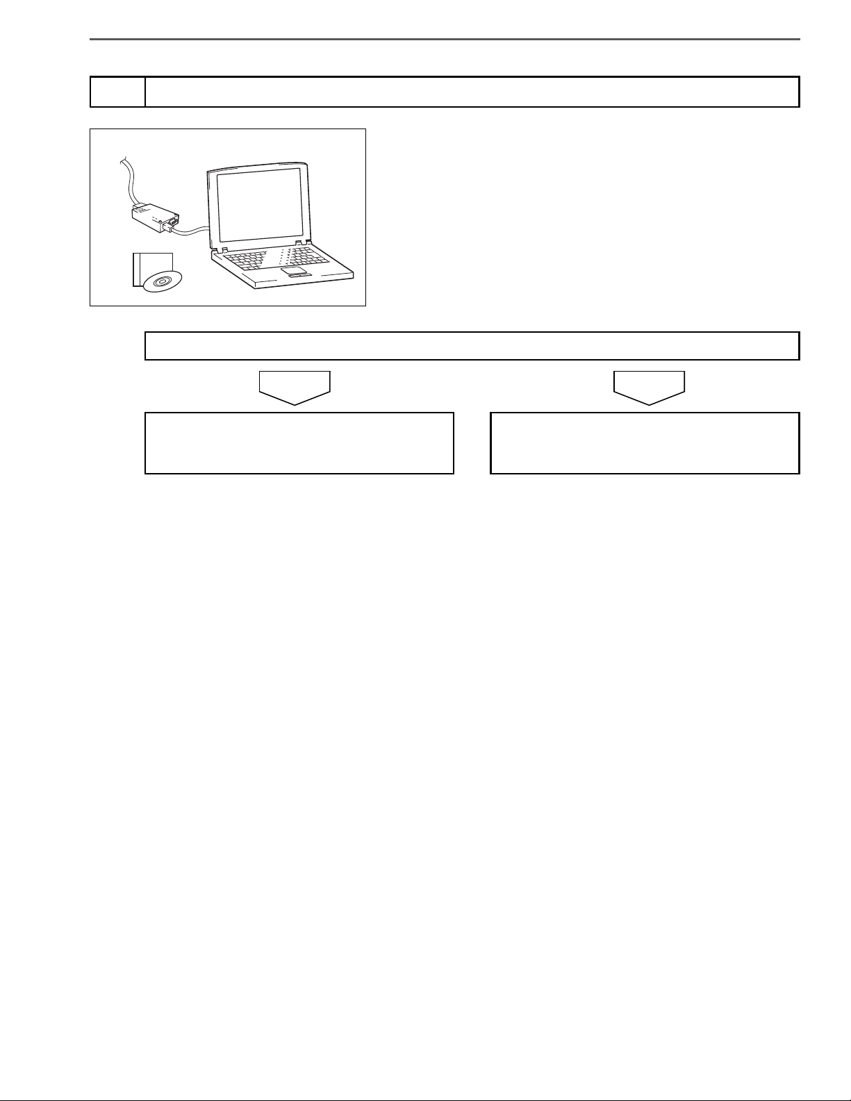
Check the DTC detected (Engine ECU) [Hino-DX]
1
Has DTC P081A been detected?
1. Set the starter switch to the "LOCK" position.
2. Disconnect the starter cut relay.
3. Set the starter switch to the "ON" position.
4. Select [Engine] and check if P081A has been detected in [Fault
Information].
Go to step 2. Replace the starter cut relay.
Perform "After-inspection work" of INFORMATION section.
Inspect the starter cut relay connector
2
1. Check the connection of the starter cut relay connector (Looseness and poor contact).
Was any failure found?
Connect securely, repair if needed.
Go to step 3.
Perform "After-inspection work" of INFORMATION section.

ENGINE CONTROL SYSTEM (J08E)4–786
NOYES
NOYES
A B
V2
V80
SAPH16F010300634
SAPH16F010300635
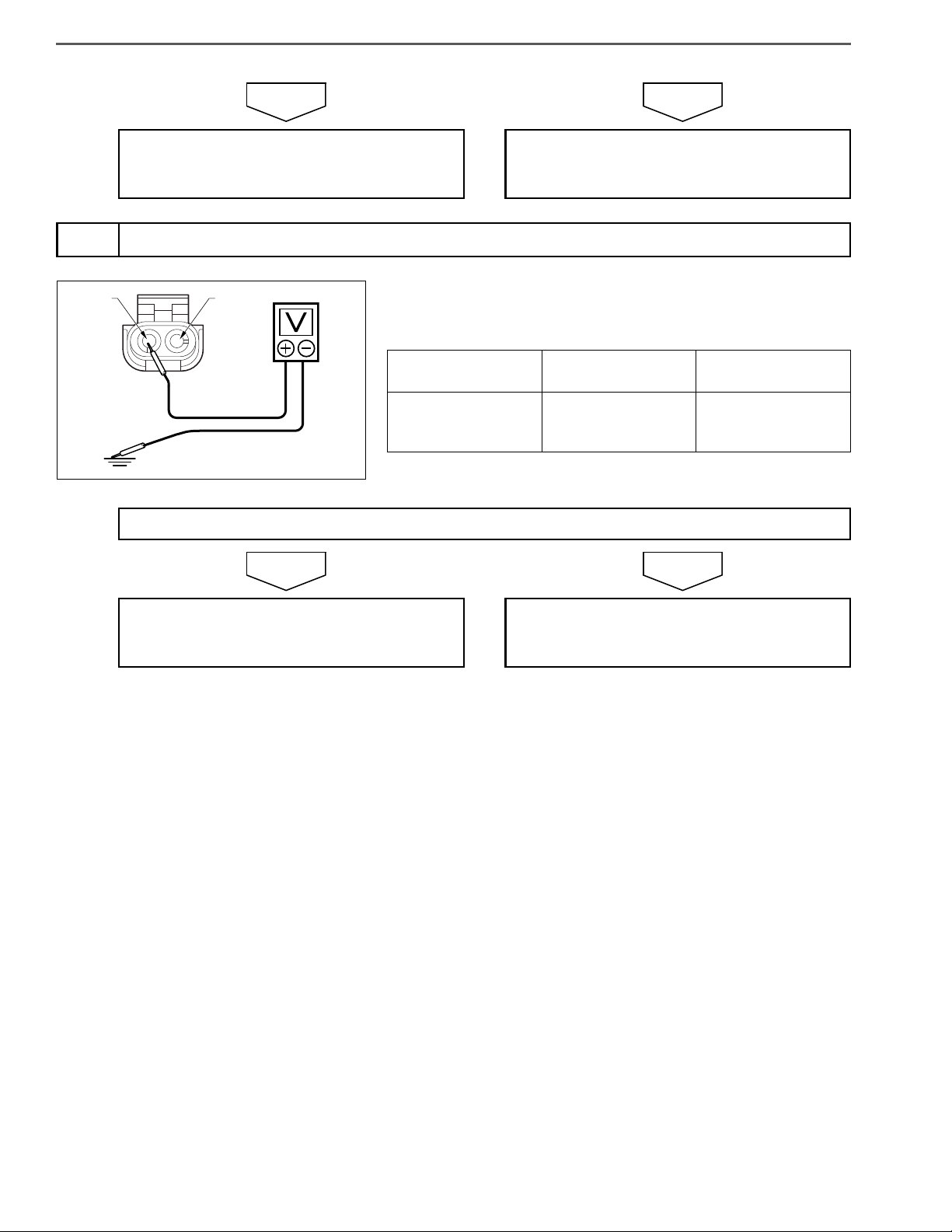
Inspect for disconnection in wire harness of starter cut relay
3
1. Set the starter switch to the "LOCK" position.
2. Connect the signal check harness to the engine ECU.
3. Set the starter switch to the "ON" position.
4. Use the electrical tester to measure the resistance between the
terminals of the engine ECU (signal check harness).
Measurement
conditions
Starter switch:
ON
Tester connections Standard values
Engine ECU (signal
check harness)
STCR(V2) – PGD4(V80)
Do the measurements meet the standard value?
Go to step 4. Repair or replace the harness.
Perform "After-inspection work" of INFORMATION section.
Check the DTC detected (Engine ECU) [Hino-DX]
4
1. Set the starter switch to the "ON" position.
2. Select [Engine] and check if P081A has been detected in [Fault
Information].
Has DTC P081A been detected?
Replace the engine ECU.
Perform "After-inspection work" of INFORMATION section.
Select
Engine
Procedure completed.
Perform "After-inspection work" of INFORMATION section.

ENGINE CONTROL SYSTEM (J08E) 4–787
CHECKLIST: P081A
DTC: P081A Starter Disable Circuit Low Inspection procedure
Step Action Description Judgement
DTC P081A
has been
detected: Go
to YES.
No DTC has
Check the
DTC detected
1
(Engine ECU)
[Hino-DX]
1. Disconnect the starter cut
relay.
2. Check if P081A has been
detected in [Engine].
been detected:
Go to NO.
Failure found:
Inspect the
starter cut
2
relay connector
Check the connection of the
starter cut relay connector
(Looseness and poor contact).
Go to YES.
No failure
found: Go to
NO.
Inspect for disconnection in
3
wire harness
of starter cut
relay
Connect the signal check harness
to the engine ECU and measure
the resistance between the terminals of the engine ECU (signal
check harness).
<Tester connections>
Engine ECU (signal check harness)
STCR(V2) – PGD4(V80)
<Standard values>
The measure-
ments meet
the standard
value: Go to
YES.
The measure-
ments do not
meet the stan-
dard value: Go
to NO.
Check
(Yes/No)
Yes No
Go to step 2.
Connect
securely,
repair if
needed.
Perform "Afterinspection
work" of
INFORMATION section.
Go to step 4.
Replace the
starter cut
relay.
Perform "Afterinspection
work" of
INFORMATION section.
Go to step 3.
Repair or
replace the
harness.
Perform "Afterinspection
work" of
INFORMATION section.
Check the
DTC detected
4
(Engine ECU)
[Hino-DX]
Check if P081A has been
detected in [Engine].
DTC P081A
has been
detected. Go
to YES.
No DTC has
been detected.
Go to NO.
Replace the
engine ECU.
Perform "Afterinspection
work" of
INFORMATION section.
Procedure
completed.
Perform "Afterinspection
work" of
INFORMATION section.

ENGINE CONTROL SYSTEM (J08E)4–788
%L9
(STA)
K01
(S+)
K04
(NC)
NK0
(NO)
(ST)
N6E
(CL2-)
%L7
(STA)
ATM starter relay
Starter cut relay
Starter cut relay
LL1K01
K0G%D7
K0G
(STCR)
LL1
Engine
ECU
SAPH16F010300636
DTC: P081B
P081B: Starter Disable Circuit High
INFORMATION
EN01H16F01030F03001099
1. Technical description
• The starter cut relay prevents further rotations of the starter when the starter switch is turned after start of the engine.
<Description of malfunction>
• Harness +B short-circuit is detected.
2. DTC set condition
(1) DTC detection condition
• Request for deactivation of starter block is in progress (while engine is stopped).
• Starter switch ON.
• Battery voltage is 10 V – 16 V.
Above conditions continue for at least 5 seconds.
(2) Judgement criteria
• Output of the starter cut relay remains at 10 V or more for 3 seconds or longer.
3. Reset condition
• After restoration to normal condition.
4. Indication, warning or system control regulation when the DTC is set.
• MIL: OFF
• Diag lamp: OFF
5. Symptoms on the vehicle when the DTC is set
<Symptoms on the vehicle due to backup control (fail safe function)>
• –
<Symptoms on the vehicle due to malfunction>
• Starter may not turn over. (If the starter turns over it will not interfere with engine operation.)
6. Pre-inspection work
• Check that the battery voltage is in the normal range.

ENGINE CONTROL SYSTEM (J08E) 4–789
7. After-inspection work
• Clear all past DTCs.
• Check that no DTC is stored after test drive.
8. Estimated failure factors
• Harness disconnection or short-circuit
• Looseness or poor contact of connector
• Starter cut relay failure
• Engine ECU failure

ENGINE CONTROL SYSTEM (J08E)4–790
NOYES
NOYES
A B
V2
V80
SAPH16F010300637
INSPECTION PROCEDURE: P081B
Inspect the starter cut relay connector
1
Was any failure found?
1. Check the connection of the starter cut relay connector (Looseness and poor contact).
Connect securely, repair if needed.
Perform "After-inspection work" of INFORMATION section.
Inspect for disconnection in wire harness of starter cut relay
2
1. Set the starter switch to the "LOCK" position.
2. Connect the signal check harness to the engine ECU.
3. Set the starter switch to the "ON" position.
4. Use the electrical tester to measure the resistance between the
terminals of the engine ECU (signal check harness).
Measurement
conditions
Starter switch:
ON
Do the measurements meet the standard value?
Go to step 2.
Tester connections Standard values
Engine ECU (signal
check harness)
STCR(V2) – PGD4(V80)
3 V or less
Go to step 3. Repair or replace the harness.
Perform "After-inspection work" of INFORMATION section.
ENGINE CONTROL SYSTEM (J08E) 4–791
NOYES
Select
Engine
SAPH16F010300638
Check the DTC detected (Engine ECU) [Hino-DX]
3
1. Set the starter switch to the "ON" position.
2. Select [Engine] and check if P081B has been detected in [Fault
Has DTC P081B been detected?
Information].
Replace the engine ECU.
Perform "After-inspection work" of INFORMATION section.
Procedure completed.
Perform "After-inspection work" of INFORMATION section.

ENGINE CONTROL SYSTEM (J08E)4–792
CHECKLIST: P081B
DTC: P081B Starter Disable Circuit High Inspection procedure
Step Action Description Judgement
Failure found:
Inspect the
starter cut
1
relay connector
Inspect for disconnection in
2
wire harness
of starter cut
relay
Check the
DTC detected
3
(Engine ECU)
[Hino-DX]
Check the connection of the
starter cut relay connector
(Looseness and poor contact).
Connect the signal check harness
to the engine ECU and measure
the resistance between the terminals of the engine ECU (signal
check harness).
<Tester connections>
Engine ECU (signal check harness)
STCR(V2) – PGD4(V80)
<Standard values>
3 V or less
Check if P081B has been
detected in [Engine].
Go to YES.
No failure
found: Go to
NO.
The measure-
ments meet
the standard
value: Go to
YES.
The measure-
ments do not
meet the stan-
dard value: Go
to NO.
DTC P081B
has been
detected: Go
to YES.
No DTC has
been detected:
Go to NO.
Check
(Yes/No)
Yes No
Connect
securely,
repair if
needed.
Perform "Afterinspection
work" of
INFORMATION section.
Go to step 3.
Replace the
engine ECU.
Perform "Afterinspection
work" of
INFORMATION section.
Go to step 2.
Repair or
replace the
harness.
Perform "Afterinspection
work" of
INFORMATION section.
Procedure
completed.
Perform "Afterinspection
work" of
INFORMATION section.

ENGINE CONTROL SYSTEM (J08E) 4–793
SAPH16F010300639
DTC: P0850
P850: Neutral switch - rationality
INFORMATION
K45NRF
N1N
(NUSW)
Engine
ECU
K45
NRF
(-)
Neutral switch
#LH#LH
%DW
(NTSW)
NRE
(+)
NRE NRF
%G1
(NSIG)
%DX
(NTSW)
ON
OFF
#D4#D4
KSM
(SW+)
EN01H16F01030F03001100
Neutral switch
%17
(SIG)
Vehicle control ECU
L98
(NUSW)
A1J
(33LD)
DPR refresh switch
1. Technical description
• Through the neutral switch, the ECU senses neutral signals when the transmission lever is in the P or N range.
<Description of malfunction>
• The neutral switch cannot correctly sense.
2. DTC set condition
(1) Check conditions
After the starter switch is set to ON position, the status described below remains for 10 seconds.
• Vehicle speed is 31.25 miles/h or higher.
• Battery voltage is in the range of 10 V to 16 V.
• After that, vehicle speed is 0 miles/h.
(2) Judgement criteria
• The neutral switch cannot be switched twice.
3. Reset condition
• Immediately after normal operation is restored.
4. Indication, warning or system control regulation when the DTC is set.
• MIL: ON
• Diag lamp: OFF
• Cruise control is not available.

ENGINE CONTROL SYSTEM (J08E)4–794
5. Symptoms on the vehicle when the DTC is set
<Symptoms on the vehicle due to backup control (fail safe function)>
• Cruise control does not work.
<Symptoms on the vehicle due to malfunction>
• –
6. Pre-inspection work
• Check that the battery voltage is in the normal range.
7. After-inspection work
• Clear all past DTCs.
• Check that no DTC is stored after test drive.
8. Estimated failure factors
• Harness disconnection or short-circuit
• Malfunction of neutral switch
• Malfunction of ECU

ENGINE CONTROL SYSTEM (J08E) 4–795
NOYES
NOYES
NRF(-) NRE(+)
SAPH16F010300640
INSPECTION PROCEDURE: P0850
Inspect the neutral switch
1
Was any failure found?
1. Check if the neutral switch is properly adjusted.
Adjust the neutral switch.
Perform "After-inspection work" of INFORMATION section.
Inspect the neutral switch connector
2
Was any failure found?
Connect securely, repair if needed.
Perform "After-inspection work" of INFORMATION section.
Inspect the neutral switch unit
3
Go to step 2.
1. Check the connection of the neutral switch connector (Looseness
and poor contact).
Go to step 3.
1. Set the starter switch to the "LOCK" position.
Do the measurements meet the standard value?
2. Disconnect the neutral switch connector.
3. Use the electrical tester to measure the resistance between the
terminals of the neutral switch.
Measurement
conditions
Starter switch:
LOCK
Tester connections Standard values
Shift lever in N posiNeutral switch
NRE – NRF
tion: < 1
Shift lever in any
other position:
ENGINE CONTROL SYSTEM (J08E)4–796
NOYES
NOYES
NRE(+) NRF(-)
SAPH16F010300641
Go to step 4. Replace the neutral switch.
Perform "After-inspection work" of INFORMATION section.
Inspect the power supply of the neutral switch
4
1. Set the starter switch to the "ON" position.
2. Use the electrical tester to measure the voltage between the NRE
terminal in the neutral switch vehicle-side connector and ground.
Measurement
conditions
Starter switch: ON
Tester connections Standard values
Neutral switch vehicle-side connector
NRE – Ground
More than 10 V
Do the measurements meet the standard value?
Go to step 5. Repair the neutral switch power circuit.
Perform "After-inspection work" of INFORMATION section.

NOYES
Inspect the neutral switch harness
A
V11
SAPH16F010300642
5
ENGINE CONTROL SYSTEM (J08E) 4–797
1. Set the starter switch to the "LOCK" position.
2. Connect the neutral switch connector.
3. Connect the signal check harness to the engine ECU vehicle-side
harness. (Do not connect the harness to the ECU.)
4. Set the starter switch to the "ON" position.
5. Use the electrical tester to measure the voltage between the terminals of the engine ECU (signal check harness) and ground.
Measurement
conditions
Starter switch:
ON
Do the measurements meet the standard value?
Replace the engine ECU.
Perform "After-inspection work" of INFORMATION section.
Tester connections Standard values
Engine ECU (signal
check harness)
NUSW(V11) – Ground
Shift lever in N position: ≥ 10 V
Shift lever in any
other position: ≤ 0.5 V
Repair or replace the harness.
Perform "After-inspection work" of INFORMATION section.

ENGINE CONTROL SYSTEM (J08E)4–798
CHECKLIST: P0850
DTC: P0850 Neutral switch - rationality Inspection procedure
Step Action Description Judgement
Failure found:
Go to YES.
Inspect the
1
neutral switch
Inspect the
2
neutral switch
connector
Inspect the
3
neutral switch
unit
Check if the neutral switch is
properly adjusted.
Check the connection of the neutral switch connector (Looseness
and poor contact).
Measure the resistance between
the terminals of the neutral
switch.
<Tester connections>
Neutral switch
NRE – NRF
<Standard values>
Shift lever in N position: < 1
Shift lever in any other position:
No failure
found: Go to
NO.
Failure found:
Go to YES.
No failure
found: Go to
NO.
The measurements meet
the standard
value: Go to
YES.
The measurements do not
meet the standard value: Go
to NO.
Check
(Yes/No)
Yes No
Adjust the
neutral switch.
Perform "Afterinspection
work" of
INFORMATION section.
Connect
securely.
repair if
needed.
Perform "Afterinspection
work" of
INFORMATION section.
Go to step 4.
Go to step 2.
Go to step 3.
Replace the
neutral switch.
Perform "Afterinspection
work" of
INFORMATION section.
Inspect the
power supply
4
of the neutral
switch
Measure the voltage between the
NRE terminal in the neutral switch
vehicle-side connector and
ground.
<Tester connections>
Neutral switch vehicle-side connector
NRE – Ground
<Standard values>
More than 10 V
The measurements meet
the standard
value: Go to
YES.
The measurements do not
meet the standard value: Go
to NO.
Go to step 5.
Repair the
neutral switch
power circuit.
Perform "Afterinspection
work" of
INFORMATION section.

ENGINE CONTROL SYSTEM (J08E) 4–799
DTC: P0850 Neutral switch - rationality Inspection procedure
Step Action Description Judgement
1. Connect the neutral switch
connector.
Inspect the
5
neutral switch
harness
2. Connect the signal check
harness, and measure the
voltage between the terminals of the engine ECU (signal check harness) and
ground.
<Tester connections>
Engine ECU (signal check harness)
NUSW(V11) – Ground
<Standard values>
The measurements meet
the standard
value: Go to
YES.
The measurements do not
meet the standard value: Go
to NO.
Shift lever in N position: ≥ 10 V
Shift lever in any other position: ≤
0.5 V
Check
(Yes/No)
Yes No
Replace the
engine ECU.
Perform "Afterinspection
work" of
INFORMATION section.
Repair or
replace the
harness.
Perform "Afterinspection
work" of
INFORMATION section.

ENGINE CONTROL SYSTEM (J08E)4–800
SAPH16F010300643
DTC: P1133
P1133: PTO accelerator sensor (Hi)
INFORMATION
PTO
accelerator sensor
(VCC)
K95
Exhaust gas
temperature
sensor
(DOC outlet)
KSE
(TEX1)
KSF
(GND1)
Differential
pressure
sensor
KSJ
(VCC)
KSK
(VOUT)
KSL
(GND)
EN01H16F01030F03001101
Exhaust gas
temperature
sensor
(DOC inlet)
LCY
(TEX3)
LCZ
(GND3)
KSE KR4
KSE KR4
LCG
(ET4+)
KSJ KUQ
KSJ KUQ
KUQ
(AVC5)
KSK KUH
KSK KUH
KUH
(EXPS)
KSF LCT
KSF LCT
LCT
(ADG9)
Engine
ECU
LCY LCG
LCY LCG
KR4
(ET2+)
1. Technical description
• The operational accelerator sensor measures accelerator opening if PTO (power take off) is used. (This applies only
to PTO-equipped vehicles.)
<Description of malfunction>
• The operational accelerator sensor cannot correctly sense.
• +B short-circuit is likely to have occurred.
2. DTC set condition
(1) Check conditions
• Starter switch ON.
• Battery voltage is in the range of 10 V to 16 V.
The conditions described above remain for 5 seconds or longer.
(2) Judgement criteria
• Sensor voltage remains at 4.82 V or higher for 3 seconds or longer.
3. Reset condition
• After normal operation is restored and starter switch is turned LOCK.

ENGINE CONTROL SYSTEM (J08E) 4–801
4. Indication, warning or system control regulation when the DTC is set.
• MIL: OFF
• Diag lamp: OFF
• Body mounting control is not available.
5. Symptoms on the vehicle when the DTC is set
<Symptoms on the vehicle due to backup control (fail safe function)>
• Body mounting control is not working.
<Symptoms on the vehicle due to malfunction>
• –
6. Pre-inspection work
• Check that the battery voltage is in the normal range.
7. After-inspection work
• Clear all past DTCs.
• Check that no DTC is stored after test drive.
8. Estimated failure factors
• Faulty harness (+B short-circuit)
• Malfunction of sensor
• Failure in engine ECU sensor power supply or internal circuit

ENGINE CONTROL SYSTEM (J08E)4–802
NOYES
NOYES
INSPECTION PROCEDURE: P1133
Inspect the PTO accelerator sensor connector
1
Was any failure found?
1. Check the connection of the PTO accelerator sensor connector
(Looseness and poor contact).
Connect securely, repair if needed.
Perform "After-inspection work" of INFORMATION section.
Inspect the PTO accelerator sensor
2
Was any failure found?
Clean the PTO accelerator sensor and install
it properly.
If damaged, replace the sensor.
Perform "After-inspection work" of INFORMATION section.
Go to step 2.
1. Check the installation of the PTO accelerator sensor.
2. Make sure there is no dirt or damage to the PTO accelerator sensor.
Go to step 3.

ENGINE CONTROL SYSTEM (J08E) 4–803
NOYES
VCCSIG
GND
SIG
SAPH16F010300644
Inspect the PTO accelerator sensor unit
3
1. Set the starter switch to the "LOCK" position.
2. Disconnect the PTO accelerator sensor connector.
3. Use the electrical tester to measure the resistance between the
terminals of the PTO accelerator sensor.
Measurement
conditions
Tester connections Standard values
PTO accelerator
Starter switch:
LOCK
sensor
SIG – VCC
More than 2
SIG – GND
Do the measurements meet the standard value?
Go to step 4. Replace the PTO accelerator sensor.
Perform "After-inspection work" of INFORMATION section.

ENGINE CONTROL SYSTEM (J08E)4–804
NOYES
B
B
V71
V68
V45
SAPH16F010300645
Inspect for short-circuit of the PTO accelerator sensor harness
4
1. Connect the signal check harness to the engine ECU. (Do not connect the harness to the ECU.)
2. Use the electrical tester to measure the resistance between the
terminals of the engine ECU (signal check harness) and ground.
Measurement
conditions
Starter switch:
LOCK
Tester connections Standard values
Engine ECU (signal
check harness)
ASCS(V68) – Ground
AVC5(V71) – Ground
ADG7(V45) – Ground
Do the measurements meet the standard value?
Go to step 5. Repair or replace the harness.
Perform "After-inspection work" of INFORMATION section.

ENGINE CONTROL SYSTEM (J08E) 4–805
NOYES
NOYES
B
B
V45
V68
V71
V68
SAPH16F010300646
Select
Engine
SAPH16F010300647
Inspect disconnection of the PTO accelerator sensor harness
5
1. Connect the PTO accelerator sensor connector.
2. Use the electrical tester to measure the resistance between the
terminals of the engine ECU (signal check harness).
Measurement
conditions
Starter switch:
LOCK
Tester connections Standard values
Engine ECU (signal
check harness)
ASCS(V68) – AVC5(V71)
ASCS(V68) – ADG7(V45)
More than 2
Do the measurements meet the standard value?
Go to step 6. Repair or replace the harness.
Perform "After-inspection work" of INFORMATION section.
Check the DTC detected (Engine ECU) [Hino-DX]
6
1. Connect the vehicle to Hino-DX.
2. Set the starter switch to the "ON" position.
3. Select [Engine] and check if P1133 has been detected in [Fault
Has DTC P1133 been detected?
Replace the engine ECU.
Perform "After-inspection work" of INFORMATION section.
Information].
Procedure completed.
Perform "After-inspection work" of INFORMATION section.

ENGINE CONTROL SYSTEM (J08E)4–806
CHECKLIST: P1133
DTC: P1133 PTO accelerator sensor (Hi) Inspection procedure
Step Action Description Judgement
Failure found:
Inspect the
PTO accelera-
1
tor sensor connector
Check the connection of the PTO
accelerator sensor connector
(Looseness and poor contact).
Go to YES.
No failure
found: Go to
NO.
Inspect the
2
PTO accelerator sensor
1. Check the installation of the
PTO accelerator sensor.
2. Make sure there is no dirt or
damage to the PTO accelerator sensor.
Failure found:
Go to YES.
No failure
found: Go to
NO.
Check
(Yes/No)
Yes No
Connect
securely,
repair if
needed.
Perform "Afterinspection
work" of
INFORMATION section.
Clean the PTO
accelerator
sensor and
install it properly.
If damaged,
replace the
sensor.
Perform "Afterinspection
work" of
INFORMATION section.
Go to step 2.
Go to step 3.
Inspect the
3
PTO accelerator sensor unit
Inspect for
short-circuit of
4
the PTO accelerator sensor
harness
Disconnect the PTO accelerator
sensor connector and measure
the resistance between the terminals of the PTO accelerator sensor.
<Tester connections>
PTO accelerator sensor
SIG – VCC
SIG – GND
<Standard values>
More than 2
Connect the signal check harness
to the engine ECU. (Do not connect harness to the ECU.)
Measure the resistance between
the terminals of the engine ECU
(signal check harness) and
ground.
<Tester connections>
Engine ECU (signal check harness)
ASCS(V68) – Ground
AVC5(V71) – Ground
<Standard values>
The measurements meet
the standard
value: Go to
YES.
The measurements meet
the standard
value: Go to
YES.
The measurements do not
meet the standard value: Go
to NO.
Go to step 4.
Go to step 5.
Replace the
sensor.
Perform "Afterinspection
work" of
INFORMATION section.
Repair or
replace the
harness.
Perform "Afterinspection
work" of
INFORMATION section.

ENGINE CONTROL SYSTEM (J08E) 4–807
DTC: P1133 PTO accelerator sensor (Hi) Inspection procedure
Step Action Description Judgement
The measurements meet
the standard
value: Go to
YES.
The measurements do not
meet the standard value: Go
to NO.
DTC P1133
has been
detected: Go
to YES.
No DTC has
been detected:
Go to NO.
Inspect disconnection of
5
the PTO accelerator sensor
harness
Check the
DTC detected
6
(Engine ECU)
[Hino-DX]
Connect the PTO accelerator
sensor connector and measure
the resistance between the terminals of the engine ECU (signal
check harness).
<Tester connections>
ASCS(V68) – AVC5(V71)
ASCS(V68) – ADG7(V45)
<Standard values>
More than 2
Check if P1133 has been
detected in [Engine].
Check
(Yes/No)
Yes No
Go to step 6.
Replace the
engine ECU.
Perform "Afterinspection
work" of
INFORMATION section.
Repair or
replace the
harness.
Perform "Afterinspection
work" of
INFORMATION section.
Procedure
completed.
Perform "Afterinspection
work" of
INFORMATION section.
 Loading...