

559-734-7451 800-367-5480 FAX 559-734-7460
INSTALLATION INSTRUCTIONS
FRONT STABILIZER BAR
F-100/F-250 2WD
Thank you for purchasing a quality Hellwig Product.
PLEASE READ THIS INSTRUCTION SHEET COMPLETELY BEFORE STARTING YOUR INSTALLATION
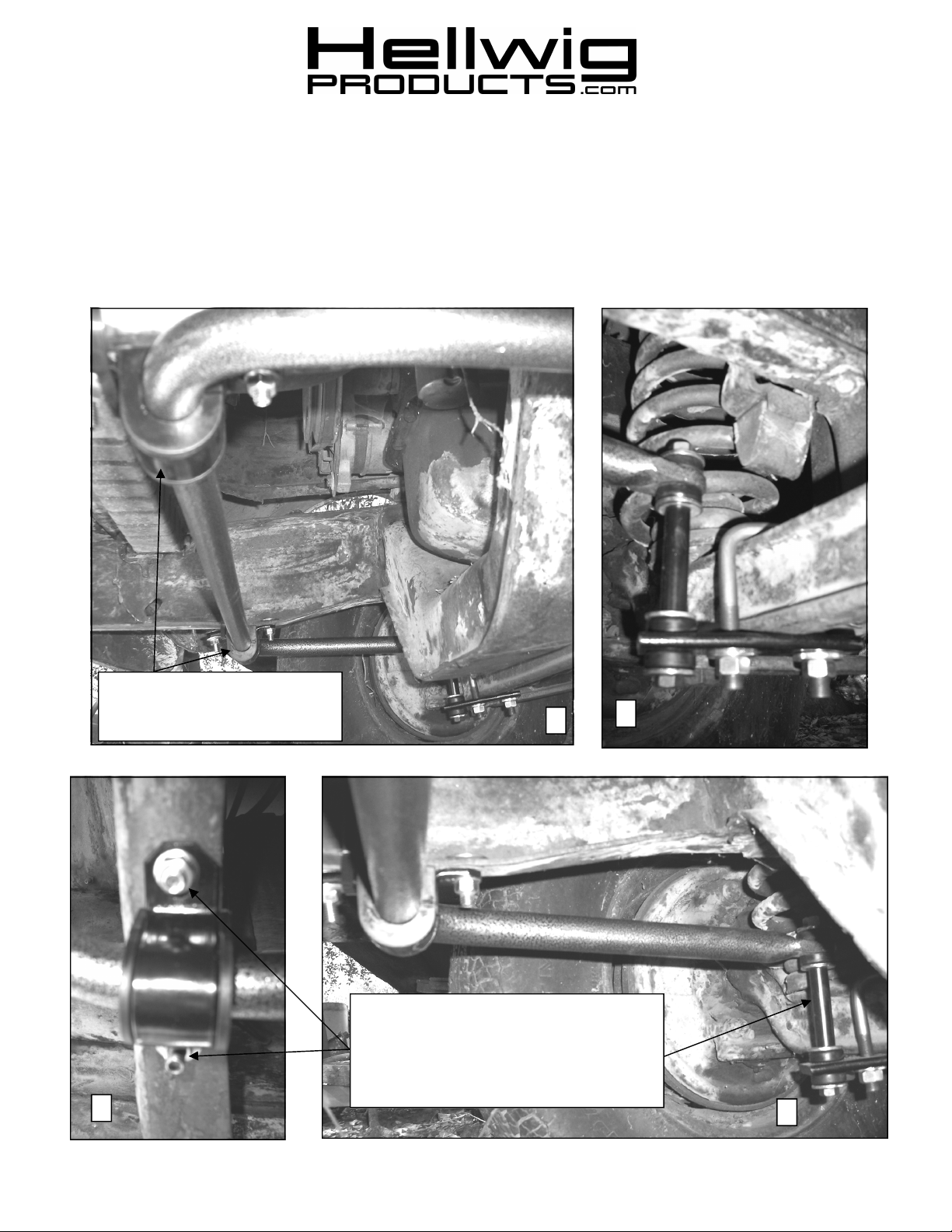
Test fit location of U-plates and
bushings before drilling holes in
frame.
3
1
Make sure end links are perpendicular to the
sway bar and bracket before drilling qty 2 .406”
diameter holes in each frame rail. Attach sway
bar to frame using supplied 3/8” bolts, washers,
and locknuts. Torque bolts to 25 ft-lb.
2
4
7422( R-7422 ) 11/14/2012

559-734-7451 800-367-5480 FAX 559-734-7460
SAFETY:
NOTE:
SUSPENSION, AS IF DRIVING DOWN THE ROAD
NOTE:
LINKS
BEFORE STARTING YOUR INSTALLATION, BE SURE TO SET PARKING BRAKE AND CHOCK TIRES.
TO EASE INSTALLATION AND TO PROPERLY ADJUST BAR, THE WEIGHT OF THE VEHICLE MUST BE ON THE
THIS UNIT IS DESIGNED TO REPLACE THE FACTORY INSALLED FRONT SWAY BAR USING THE FACTORY END
.
BOLT SIZE: 3/8” = 20-30 ft. lbs. – 7/16” = 35-45 ft. lbs. – ½” = 50-70 ft. lbs. – 9/16” = 70-90 ft. lbs.
TORQUE TABLE
.
DO NOT RAISE VEHICLE BY FRAME.
1. For best results, the sway bar should be installed with the weight of the vehicle on the suspension. If additional clearance is required, the vehicle should be supported on ramps.
2. Loosely attach the end link brackets to the suspension I-beams as shown in Photo 2 using the the supplied ubolts, 1/2” locknuts and thick washers.
3. Lubricate the inside diameter of the poly bushings and attach to the sway bar as shown in the photos.
4. Attach sway bar to end links as shown in Photo 2 using the 7/16” x 6” bolt, 1/8” thin washers and bushings.
Tighten the bolts until the bushings bulge slightly
5. Attach u-plates to sway bar bushings and raise sway bar up to the frame using a floor jack or equivalent.
Center the sway bar and brackets on the vehicle. When the sway bar is centered on the frame and the brackets are located evenly on the I-beams, mark locations on frame rail for the holes to attach U-plates to the rail.
6. Drill qty 2 .406” diameter holes in the lower flange of each frame rail in the locations marked in step 5.
7. Attach Sway bar to frame rail with 3/8”x 1-1/4” bolts, washers, and locknuts.
8. Center sway bar and torque U-bolts on I-beams to 60 ft-lb. Torque frame fasteners to 25 ft-lb.
9. Bounce the vehicle and check for clearance on all the undercarriage components. Be sure that all nuts and
bolts securely tightened. Check and see that all suspension components, wires, fuel and brake lines etc. are all
clear of this installation and cannot be damaged. Recheck your installation after one (1) week of driving and
every thirty days thereafter.
ATTENTION INSTALLER: BE SURE THAT THE CUSTOMER RECEIVES THIS INSTRUCTION
SHEET, ALL IMORTANT NOTE CARDS AND THE WARRANTY FORM
7422( R-7422 ) 11/14/2012
 Loading...