

Page 1
559-734-7451 800-367-5480 FAX 559-734-7460
INSTALLATION INSTRUCTIONS
Thank you for purchasing a quality Hellwig Product.
PLEASE READ THIS INSTRUCTION SHEET COMPLETELY BEFORE STARTING YOUR INSTALLATION PROCEDURES.
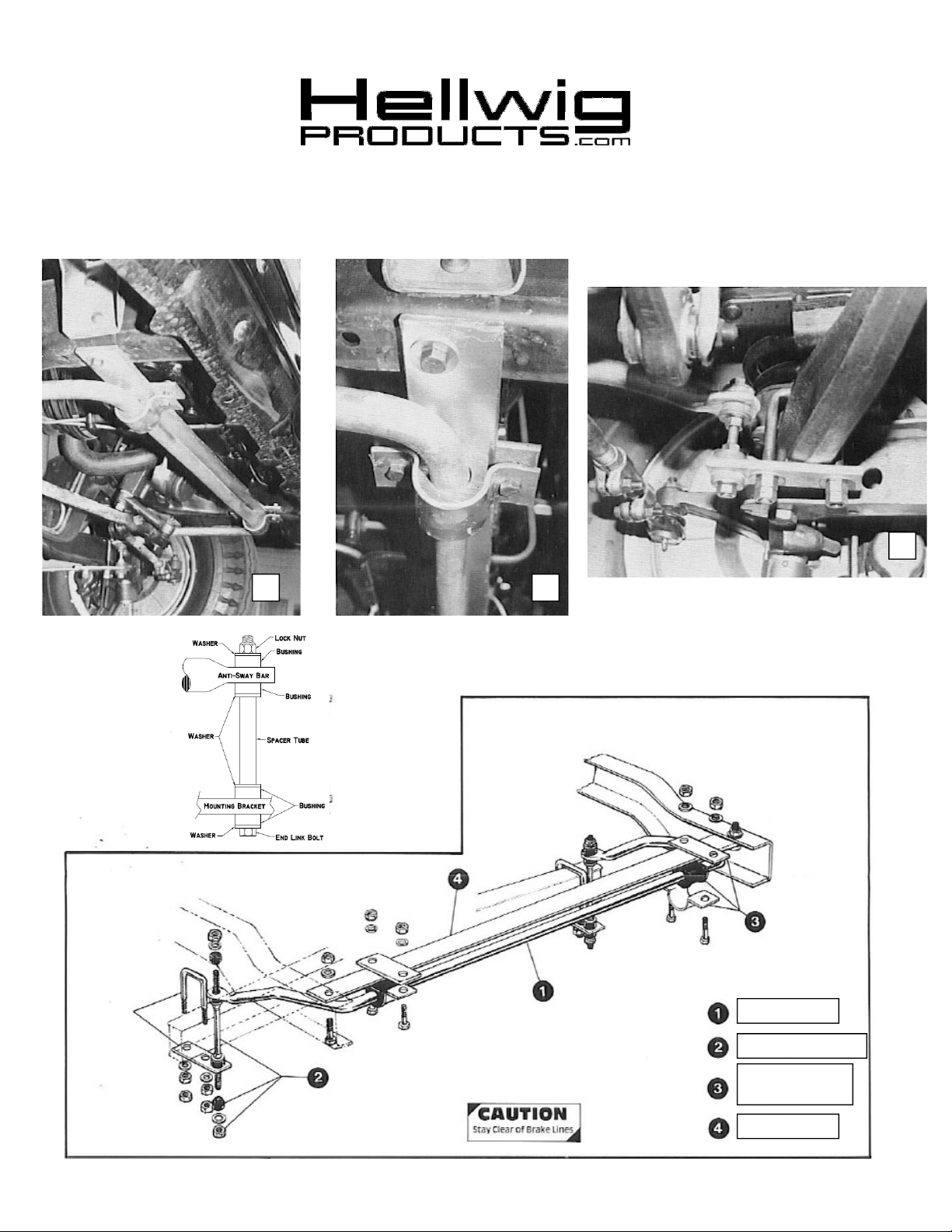
2 1
3
Sway Bar
End Link Assembly
D-Bushing and
U-Plate
Cross Member
( R-234 ) 11/29/2012
Page 2

559-734-7451 800-367-5480 FAX 559-734-7460
TORQUE TABLE
BOLT SIZE: 3/8” = 20-30 ft. lbs. – 7/16” = 35-45 ft. lbs. – 1/2” = 50-70 ft. lbs. – 9/16” = 70-90 ft. lbs
SAFETY:
NOTE: TO EASE INSTALLATION AND TO PROPERLY ADJUST THE SWAY BAR, THE WEIGHT OF THE VEHICLE MUST BE
PARK YOUR VEHICLE ON A FLAT LEVEL SURFACE, SET THE PARKING AND CHOCK THE FRONT TIRES.
ON THE SUSPENSION AS IF DRIVING DOWN THE ROAD. DO NOT RAISE THE VEHICLE BY THE FRAME.
1. As in Photos No. 1 and No. 2, mount the cross member to frame using the holes on the bottom
frame flange just under the body frame bracket. Use the 7/16 cap screw, washers and 7/16 nuts as
provided. Tighten securely and double nut.
2. Using the U-plate and plates provided, mount the sway bar to the cross member. With the Dbushing on the bar, install the plates and bar to the cross member. Do not tighten. NOTE: Be
sure the sway bar arms are above the tie rod assemblies.
3. Install the I-Beam, U-bolt assemblies as in Photo No. 3. Drop the U-bolt over I-Beam and install
the plate as shown Photo No. 3. Do not tighten at this point.
4. Assemble the end link as illustrated in the line drawing. Do not over tighten the bushings.
Tighten just until the bushing begins to bulge slightly.
5. Align the sway bar so that it is centered along the frame. Now align the end link so that is is vertical or as near vertical as possible. Do this by moving the sway bar and U-bolts to the proper positions. Tighten the U-bolts on the I-Beams and double nut. Now tighten the D-bushing and
bracket.
6. Check the torque following the Torque Table above.
7. Bounce the vehicle while turning the wheels to full lock left and right and check for clearance on
all undercarriage components. Be sure all nuts and bolts are securely fastened and double nuts are
used where necessary or provided.
8. Recheck your installation after a test drive, look for clearance on gas lines, steering, exhaust
pipes, brake lines, wiring, etc. After one week of driving check your installation and periodically
thereafter.
Maintenance and Inspection:
Your Hellwig Suspension Product is built to last. However, as with all vehicle systems, it requires
routine inspection. Inspect your Hellwig installation looking for secure hardware and tight fitting
brackets and bushings. If you do not perform this inspection, have your professional mechanic inspect as described.
ATTENTION INSTALLER: BE SURE THAT THE CUSTOMER RECEIVES THIS INSTRUCTION
( R-234 ) 11/29/2012
SHEET, ALL IMPORTANT NOTE CARDS AND THE WARRANTY FORM.
 Loading...