

Page 1
INSTALLATION INSTRUCTIONS
Rear Stabilizer Bar
Workhorse W20-W24 Models
Thank you for purchasing a quality Hellwig Product.
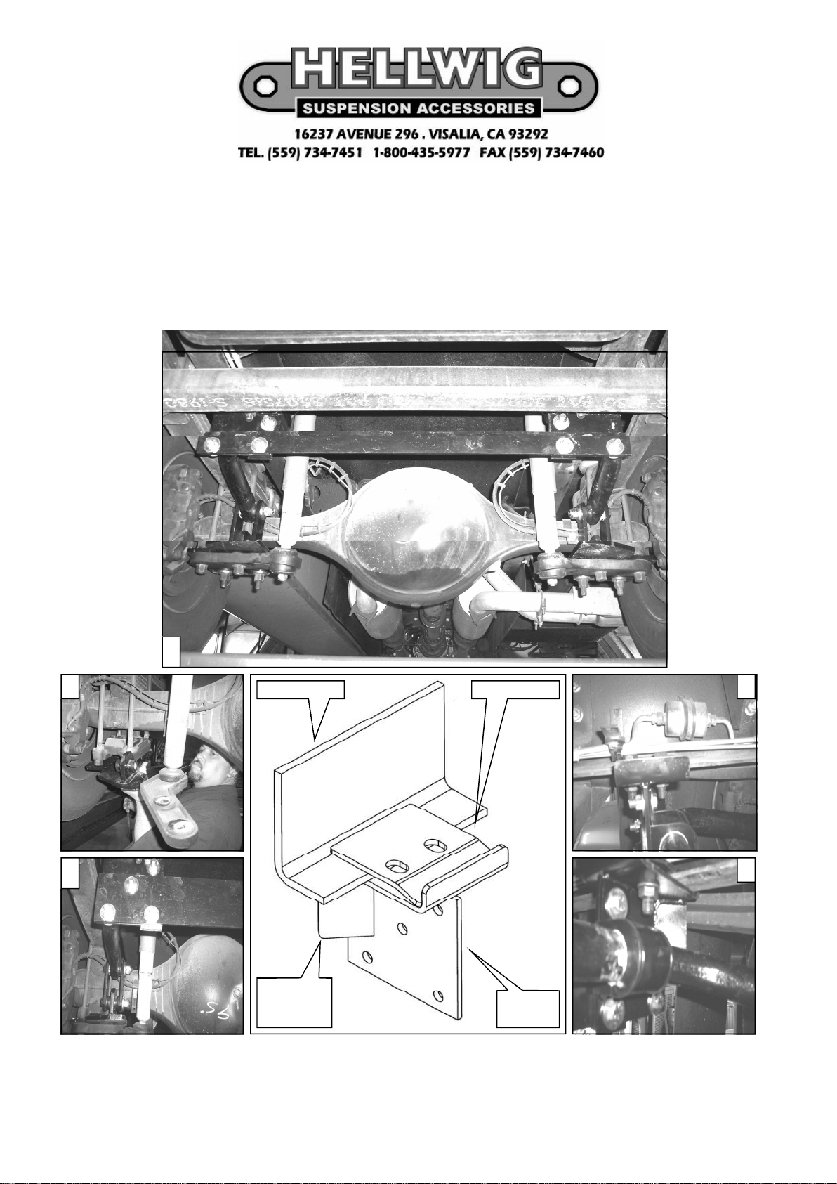
1
2 3
4 5
GUSSET TO
BACK OF
AXLE
PINCH PLATEFRAME RAIL
FRAME
BRACKE
7237 ( R-7237 ) 05/08/06
Page 2

PARTS LIST
RSB # 7237
PART # QTY DESCRIPTION
20217219 1 1-3/4” SWAY BAR
20227219 1 1-3/4” CUT SWAY BAR
111000570 4 5/8” POLY BUSHING
111000571 2 SMALL BUSHING SLEEVE
111000572 2 LARGE BUSHING SLEEVE
20800161 1 CROSSMEMBER
72370 1 REAR SWAY BAR ISNTALL/KIT
111000889 2 1-3/4” POLY BUSHING
20800173 1 LH LOWER ANGLE BRACKET
20800174 1 RH LOWER ANGLE BRACKET
20800172 2 PINCH PLATE
20800787 2 MODIFIED U-PLATE
20800889 2 FRAME BRACKET
20800307 4 END LINK SHACKLE
20800040 1 RH AXLE U-BOLT PLATE
20800039 1 LH AXLE U-BOLT PLATE
125020066 1 COMPLETION KIT
101500622 4 5/8” X 2” FRAME BOLT
107700622 4 5/8” FRAME NUT
101500125 8 1/2” X 1-1/2” CAP SCREW
107521044 8 1/2” LOCK NUT
102520043 16 1/2” FLAT WASHER
101500138 4 5/8” X 3-3/4” CAP SCREW
107700058 4 5/8” LOCK NUT
102500137 4 5/8” X 1-3/4” X 3/16” THICK FLAT WASHER
135007237 1 INSTRUCTION SHEET ( R-7237 )
7237 ( R-7237 ) 05/08/06
Page 3

TORQUE TABLE
BOLT SIZE: 3/8” =20-30 ft. lbs. – 7/16” = 35-45 ft. lbs. – ½” = 50-70 ft. lbs. – 9/16” = 70-90 ft. lbs.
SAFETY: BEFORE STARTINGYOUR INSTALLATION, BE SURE TO SET PARKING BRAKE AND CHOCK TIRES.
NOTE: TO EASE INSTALLATION AND TO PROPERLY ADJUST BAR, THE WEIGHTOF THE VEHICLEMUST BE
ON THE SUSPENSION, AS IF DRIVING DOWN THE ROAD. DO NOT RAISE VEHICLE BY FRAME.
NOTE: THIS SWAY BAR WILL MOUNT TO THE REAR OF THE REAR AXLE BETWEEN THE FACTORY
CROSSMEMBER AND THE SHOCK ASSEMBLIES, ARMS WILL BE POINTING TOWARDS THE BACK OF THE
REAR AXLE.
1. Remove the rear axle u-bolt nuts. Install the left & right axle plates on the bottom side of the factory axle
plates. NOTE : the mount tabs for the rear sway bar will be towards the inside of the coach both sides. Reinstall the axle nuts and torque to the factory specified rate. ( CAUTION : gas pressure shocks are very stiff
and hard to install. Recommend using limiting straps or zip ties to hold the shocks in place to ease the installation later ). ( SEE PHOTO # 2 ).
2. Measure from back of the rear axle approximately ( 17-1/2” ) towards the rear of the coach. This is the area
that the Pinch plate & Frame brackets will be mounted to the lower lip of the frame rails. Area will be close to
factory cross-member. ( CAUTION : on the drivers side check for clearance for the fuel filter bracket, slight
modification may be required for proper fit ). ( SEE PHOTOS # 1 & 3 ).
3. With the mounting hardware provided install the Pinch plate & Frame brackets to the lower lip of the frame
rails. The welded gussets on the frame brackets will towards the front of the coach. The lower lip of the frame
rail will be sandwiched between the Pinch plate and the Frame bracket. ( SEE DRAWING ). Leave loose at
this time to allow for adjustment later.
4. Locate the Cross-member and install to the mounted Frame brackets on the frame rails with the hardware provided. The cross-member will be positioned between the factory cross-member and the top shock mount
brackets on the vehicles frame. Leave loose at this time to allow for adjustment later. ( SEE PHOTO # 1 ) .
5. Locate and assemble the end link assemblies. Position the sway bar between the factory cross member and the
rear shocks and attach the sway bar arms to the end link assemblies. ( SEE PHOTO # 4 ) .
6. Install the poly D-bushings on the sway bar. Rotate the sway bar up to the cross-member provided. Using the
hardware provided install the U-plates over the D-bushings and attach to the cross-member. Leave loose at
this time to allow for adjustments later. ( SEE PHOTO # 5 ).
7. With the say bar mounted on the cross-member slide the Pinch plate and Frame brackets forward or backwards to allow the end links to be straight up and down as possible. Check for clearance on all undercarriage
components, ie: exhaust, shocks, fuel lines & filter, brake lines etc. . With the sway bar properly mounted and
the end links straight up and down as possible tighten all mounting hardware to their specified rates. Start at
the axle plates or end links this will center the sway bar onto its mounts or U-plates. Torque all mounting
hardware to the specified rate. Test drive the vehicle and re-check your installation and re-adjust if necessary.
Re-check your installation on a monthly regular basis thereafter.
ATTENTION INSTALLER: BE SURE THAT THE CUSTOMER RECEIVES THIS INSTRUCTION
SHEET, ALL IMPORTANT NOTE CARDS AND THE WARRANTY
FORM
7237 ( R-7237 ) 05/08/06
 Loading...