

Page 1
INSTALLATION INSTRUCTIONS
7268 Adjustable Rear Stabilizer Bar
1999-2010 2WD & 4WD F-250/F-350 Super Duty Except Dual Wheels
Thank you for purchasing a quality Hellwig Product.
1 2 3
1
9/16” Nut
2 3 4
3/4” ID Houglass
Bushings on frame
end.
5/8” ID Houglass
Bushings on sway
bar end.
7268 ( R-7268) 11/19/2010
Page 2
559-734-7451 800-367-5480 FAX 559-734-7460
TORQUETABLE
BOLT SIZE: 3/8” = 20-30 ft. lbs. – 7/16” = 35-45 ft. lbs. – ½” = 50-70 ft. lbs. – 9/16” = 70-90ft. lbs.
SAFETY: BEFORESTARTINGYOURINSTALLATION, BE SURE TO SETPARKING BRAKE ANDCHOCK THEWHEELS.
NOTE: TO EASE INSTALLATION AND TOPROPERLY ADJUSTBAR, THE WEIGHT OF THE VEHICLEMUST BE ON THE SUSPEN-
SION, AS IF DRIVING DOWN THE ROAD. DO NOT RAISE THE VEHICLE BY FRAME.
NOTE: THIS UNIT IS DESIGNED TO REPLACE THE FACTORY INSTALLED REAR ANTI-SWAYBAR OR AS AN ADDITION IF THE
REAR ANTI-SWAY IS NOT FACTORY SUPPLIED.
NOTE: THIS KIT INCLUDES LOCK NUTS WHICH REQUIRE TIGHTENING WITH A WRENCH AFTER BEING STARTED BY HAND.
1. Remove the factory installed rear anti-sway bar (if equipped) and all factory supplied hardware.
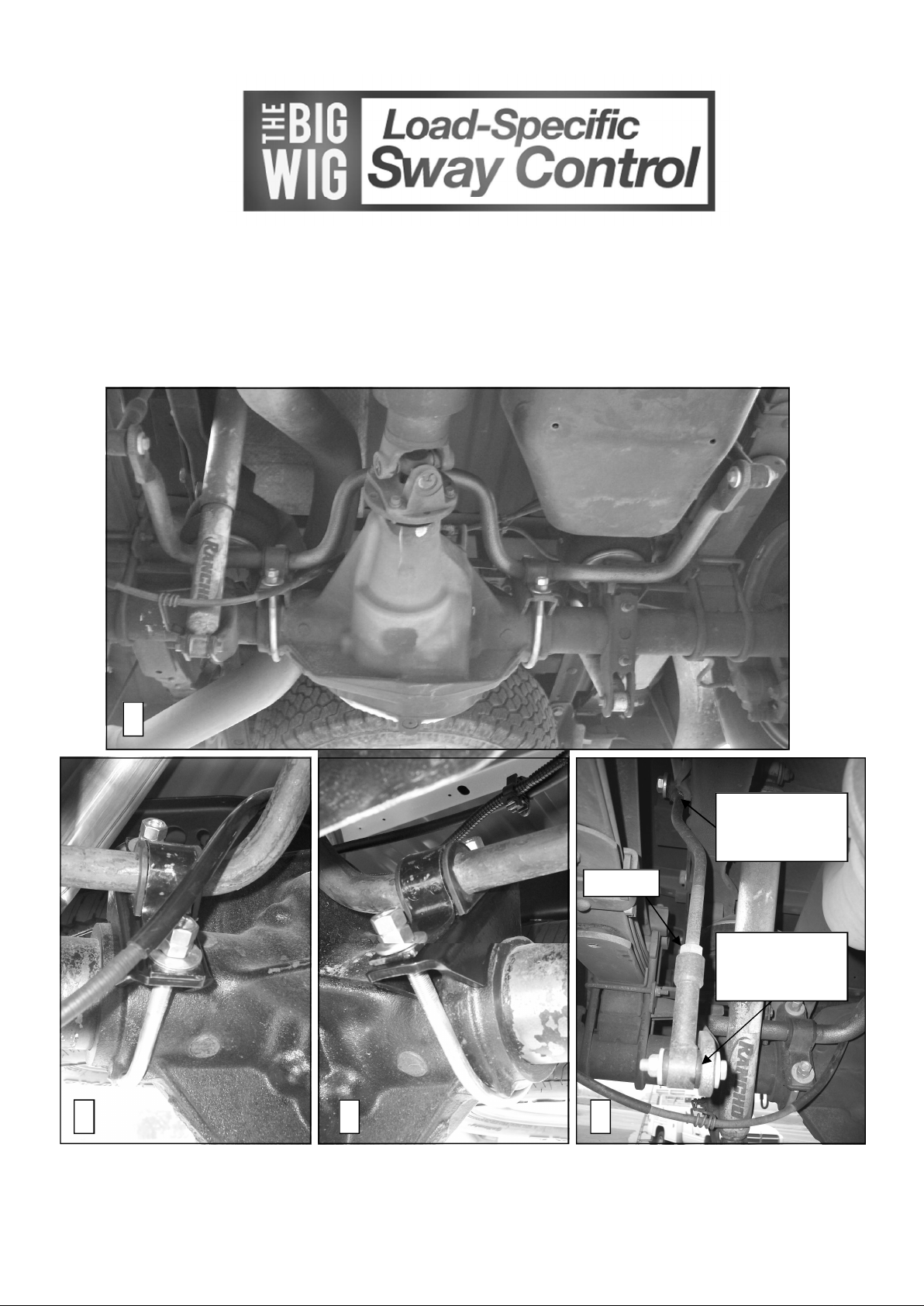
2. Locate the half round cast lugs on the differential housing at each side near the axle tubes. Install the U-bolts on
the axle between these lugs and install the saddles over the legs of the U-bolts. Orient the saddle brackets as
shown in photos (2&3).
3. Lubricate and place the D-shaped poly-bushings onto the straight areas of the bar on each side of the center
clearance hump. Place the U-plates over the bushings on the bar, position the U-plates and poly-bushings as
close as possible to the center of the hump.
4. Disconnect the emergency cable bracket located on the passenger side shock mount. Save bolt to reattach the
bracket later. Move emergency brake cable out of the way to ease sway bar installation.
5. Place the bar with the bushings and U-plates up over the top of the differential housing. Align the bushings and
U-plates so that they align with the U-bolts on the differential. Place the bar bushings and U-plates onto the Ubolts and saddles , attach them with the flat washers and locknuts provided. Leave loose at this time to allow
for adjustment later.
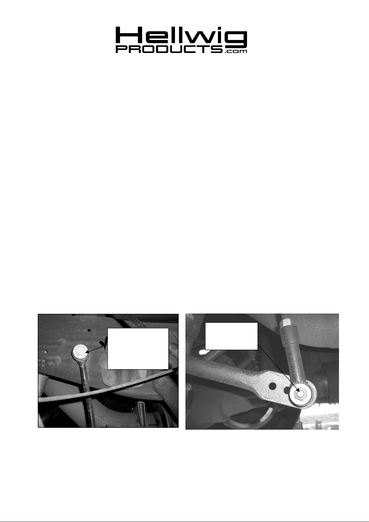
6. Locate the end links and assemble with the poly bushings and 9/16” nut as in photo (4). Insert the 3/4” ID hourglass bushings and matching inserts in the loops of the end link that will attach to the frame rail. Insert the 5/8”
ID hourglass bushings and matching inserts in the loops of the end link that will attach to the sway bar. Lubricate hourglass bushings and insert first and then insert sleeve.
3/4” ID Houglass
Bushings on frame
end. Attach with 1/2”
Hardware and torque
to 50-60 ft-lb.
Attach end link to
end hole for initial
adjustment.
7268 ( R-7268) 11/19/2010
Page 3

559-734-7451 800-367-5480 FAX 559-734-7460
7. Attach the end links to the frame rail as shown in photos (4&5) using the 1/2 X 2 –1/2” bolt, washers and locknut.
8. Center sway bar on the differential and move the axle mounting hardware so the bar is aligned properly. Be sure
to move any lines, wires or hoses on the axle or the inside of the frame to avoid any damage. Rotate bar up and
down to make sure there is adequate clearance to all axle and undercarriage components as the suspension articulates. When bar is centered and proper clearances verified, tighten axle U-bolt locknuts to 60 ft-lb.
9. Attach lower end of end link to outer hole of swaybar as shown in photo six (6) using 7/16 X 2-3/4” bolt, washer
and locknut. Adjust end links so that end link bolt will clear fuel tank. Tighten 1/2” bolt to 50-60 ft-lb and 7/16”
bolt to 35-40 ft-lb. Tighten 9/16” adjustment nut on end link to 70 ft-lb.
10. Reattach emergency brake bracket and torque to factory specification.
11. Bounce the vehicle checking for clearance on all undercarriage components shocks, exhaust etc… test drive the
vehicle and recheck your installation. Recheck periodically on a regular basis thereafter.
12. The sway bar arms have three mounting holes. Mounting the sway bar on the outer hole is the nominal position.
For firmer settings, use the inner holes. We recommend starting with the outer mounting hole as in photo ( 2 )
until you are accustomed to the vehicles new handling characteristics. Then select the mounting point that best
fits your driving style
ATTENTION INSTALLER: BE SURE THE CUSTOMERRECEIVES THIS INSTRUCTION SHEET, ALL WARNING
AND NOTE CARDS AND THE WARRANTY FORM.
7268 ( R-7268) 11/19/2010
 Loading...