

Page 1
559-734-7451 800-367-5480 FAX 559-734-7460
INSTALLATION INSTRUCTIONS
Adjustable Rear Stabilizer Bar
Ford F-250/F-350
Thank you for purchasing a quality Hellwig Product.
PLEASE READ THISINSTRUCTION SHEETCOMPLETELY BEFORE STARTINGYOUR INSTALLATION
1 2
1
2
3
7282( R-7282) 10/30/2012
Page 2
559-734-7451 800-367-5480 FAX 559-734-7460
TORQUETABLE
BOLT SIZE: 3/8” = 20-30 ft. lbs. – 7/16” = 35-45 ft. lbs. – ½” = 50-70 ft. lbs. – 9/16” = 70-90 ft. lbs.
SAFETY: BEFORE STARTING YOUR INSTALLATION, BE SURE TO SET PARKING BRAKE ANDCHOCK THE WHEELS.
NOTE: TO EASE INSTALLATION AND TO PROPERLY ADJUST BAR, THE WEIGHT OF THE VEHICLE MUST BE ON THE SUSPEN-
SION, AS IF DRIVING DOWN THE ROAD. DO NOT RAISE THE VEHICLEBY FRAME.
NOTE: THIS UNIT IS DESIGNED TO REPLACE THE FACTORY INSTALLED REAR ANTI-SWAY BAR OR AS AN ADDITION IF THE
REAR ANTI-SWAY IS NOTFACTORY SUPPLIED.
NOTE: THIS KIT INCLUDESLOCK NUTS WHICH REQUIRETIGHTENING WITH A WRENCH AFTER BEING STARTED BY HAND.
1. Remove the factory installed rear anti-sway bar (if equipped) and all factory supplied hardware. See Photo 4 and
step 5 for removal of factory installed end link.
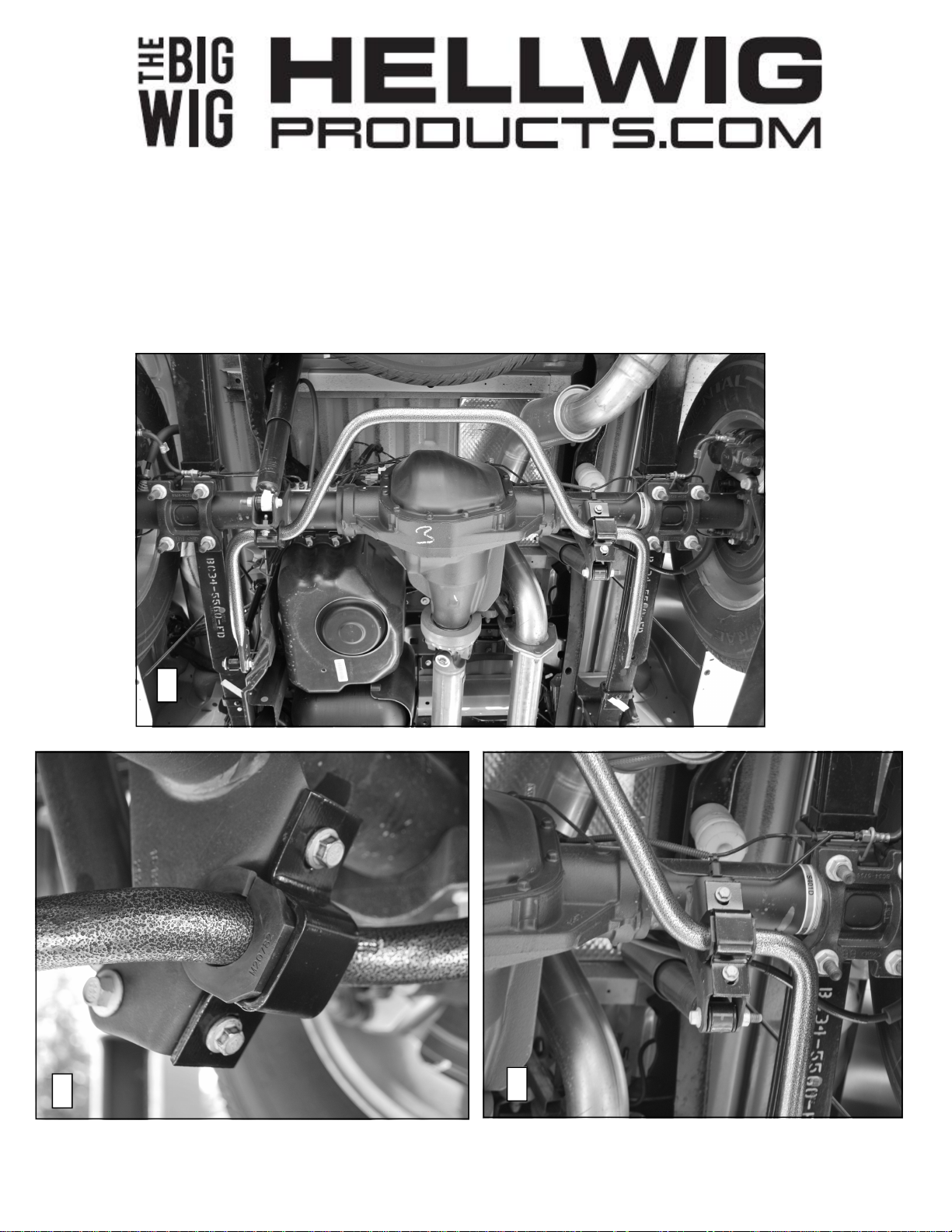
2. Lubricate and place the D-shaped poly-bushings onto the straight areas of the bar on each side of the center
clearance hump. Place the square U-plates over the flat side of the bushings on the bar.
3. Bolt the U-plates to the shock mounts on the opposite side of the shock using the included M10 bolts. See Photos 2 and 3.
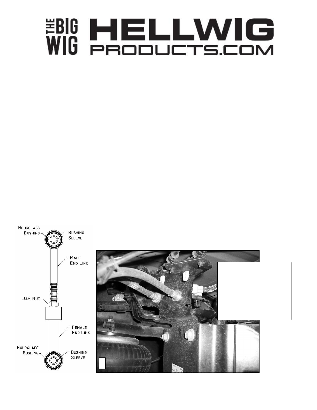
4. Locate the end links and assemble with the poly bushings and 9/16” jam nut as in Diagram below. Insert the 3/4”
ID hourglass bushings and matching inserts in the loops of the male end link that will attach to the frame rail.
Insert the 5/8” ID hourglass bushings and matching inserts in the loops of the female end link that will attach to
the sway bar. Lubricate hourglass bushings and insert first and then lubricate the outside and insert sleeve.
5. Installation of driver side end link will be easer if bracket in Photo 4 below is unbolted from fuel tank support.
DO NOT DISCONNECT BRAKE LINES OR ELECTRICAL CONNECTIONS, ONLY UNBOLT THE
BRACKET TO ALLOW EASIER ACCESS TO END LINK BOLT ON DRIVER SIDE.
Removal of stock end link and
installation of new end link on
driver side will be easier if this
bracket is unbolted and moved
away from frame rail. Do not
disconnect hoses or electrical
lines. Take care not to damage
brake line or hoses. Replace
bracket after installing end link.
4
7282( R-7282) 10/30/2012
Page 3
559-734-7451 800-367-5480 FAX 559-734-7460
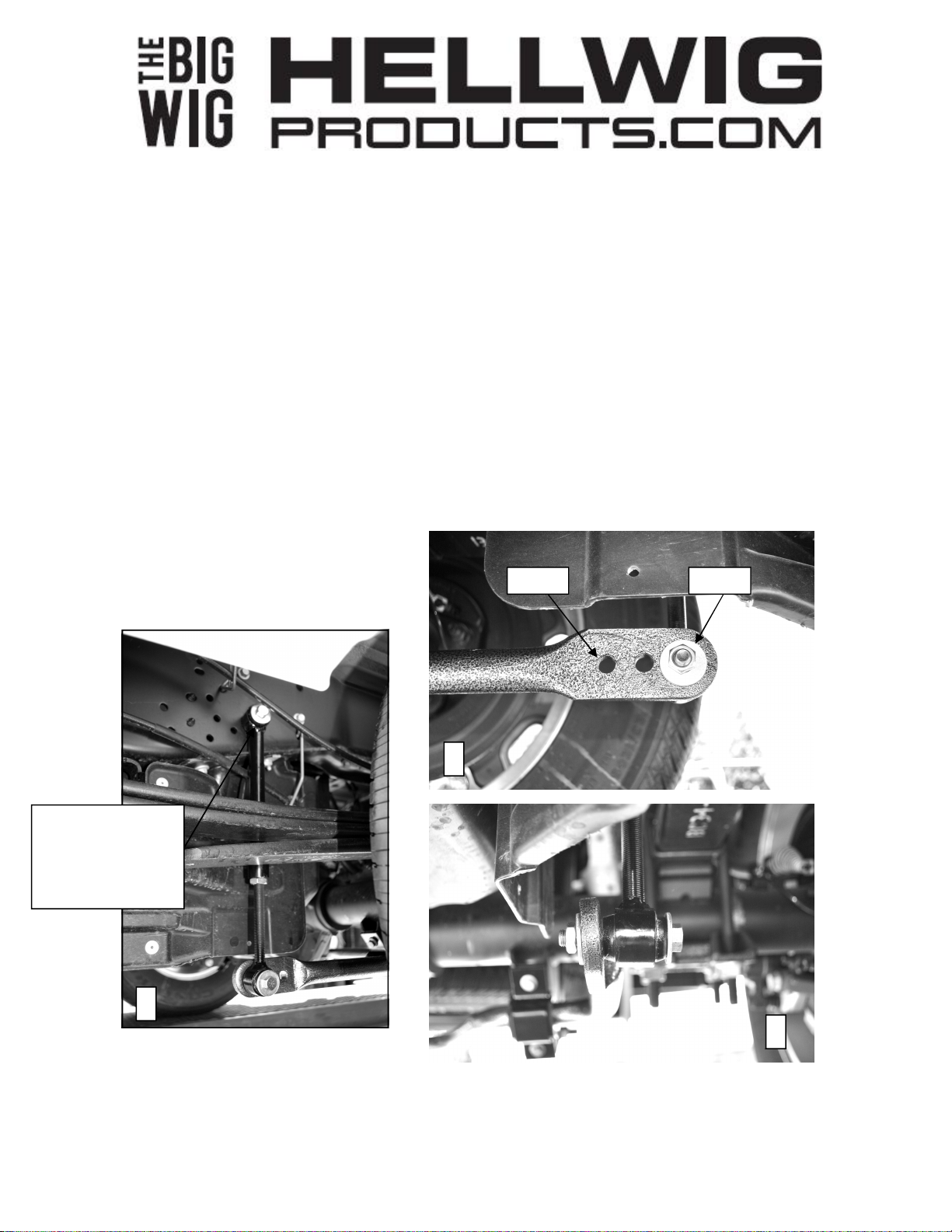
6. Attach the end links to the frame rail as shown in Photo 5 using the 1/2 X 3” bolt, washers and locknut.
7. Center sway bar on the differential. Be sure to move any lines, wires or hoses on the axle or the inside of the
frame to avoid any damage. Rotate bar up and down to make sure there is adequate clearance to all axle and
undercarriage components as the suspension articulates. When bar is centered and proper clearances verified,
tighten shock mount U-plate bolts to 25 ft-lb.
8. Attach lower end of end link to outer hole of sway bar as shown in Photos 6 and 7 using 7/16 X 3” bolt, washer
and locknut. Adjust end link length so that end link bolt will clear fuel tank and keep the sway bar arms as parallel to the ground as possible. Tighten 1/2” bolt to 50-60 ft-lb and 7/16” bolt to 35-40 ft-lb. Tighten 9/16” adjustment nut on end link to 70 ft-lb.
9. Bounce the vehicle checking for clearance on all undercarriage components shocks, exhaust etc. Test drive the
vehicle and recheck your installation. Recheck periodically on a regular basis thereafter.
10. The sway bar arms have three mounting holes. Mounting the sway bar on the outer hole is the nominal position.
For firmer settings, use the inner holes. We recommend starting with the outer mounting hole until you are accustomed to the vehicles new handling characteristics. Then select the mounting point that best fits your driving
style
ATTENTION INSTALLER: BE SURE THE CUSTOMER RECEIVES THIS INSTRUCTION SHEET, ALL WARNING
AND NOTE CARDS AND THE WARRANTY FORM.
Stiffest Softest
6
3/4” ID Hourglass
Bushings on frame
end. Attach with 1/2”
Hardware and torque
to 50-60 ft-lb.
5
7
7282( R-7282) 10/30/2012
 Loading...