

Page 1
559-734-7451 800-367-5480 FAX 559-734-7460
INSTALLATION INSTRUCTIONS
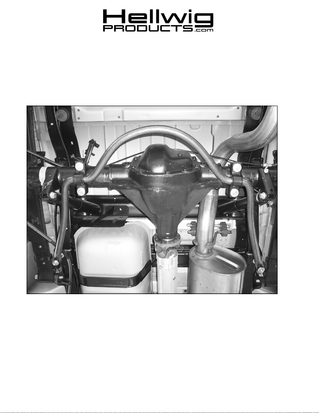
7183 Rear Stabilizer Bar
Ford E-350 Single Wheel
Thank you for purchasing a quality Hellwig Product.
PLEASE READ THIS INSTRUCTION SHEET COMPLETELY BEFORE STARTING YOUR INSTALLATION
TORQUE TABLE
BOLT SIZE: 3/8” = 20-30 ft. lbs. – 7/16” = 35-45 ft. lbs. – ½” = 50-70 ft. lbs. – 9/16” = 70-90 ft. lbs.
SAFETY: BEFORE STARTING YOUR INSTALLATION, BE SURE TO SET PARKING BRAKE AND CHOCK TIRES.
NOTE: TO EASE INSTALLATION AND TO PROPERLY ADJUST BAR, THE WEIGHT OF THE VEHICLE MUST BE
ON THE SUSPENSION, AS IF DRIVING DOWN THE ROAD. DO NOT RAISE VEHICLE BY FRAME.
NOTE: THIS KIT INCLUDES LOCK NUTS WHICH REQUIRE TIGHTENING WITH A WRENCH AFTER BEING STARTED
BY HAND.
7183 (R-7183)
02/06/2007
Page 2
559-734-7451 800-367-5480 FAX 559-734-7460
2
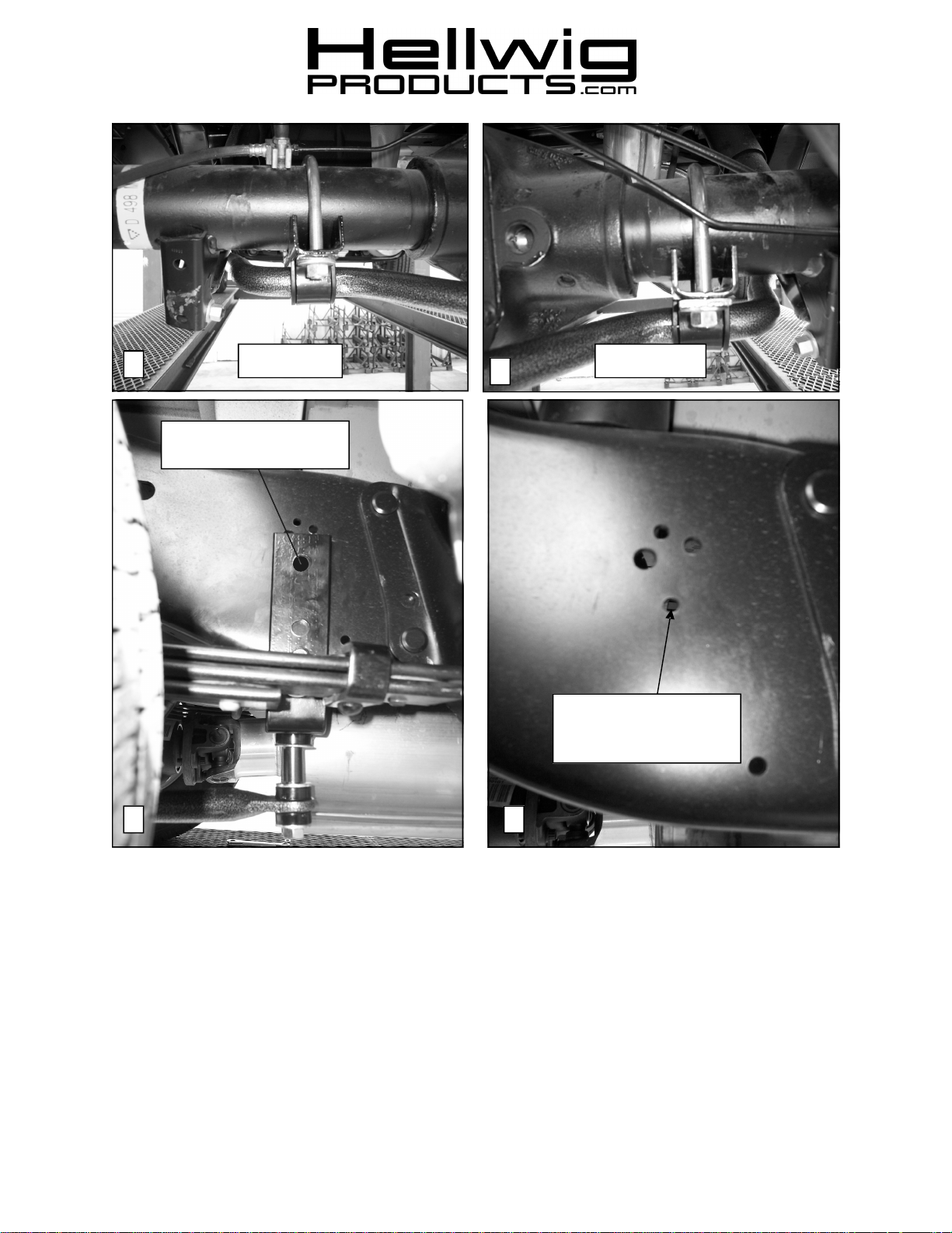
Align hole in bracket with
existing slotted hole
Driver Side Passenger Side
3
If this hole exits, enlarge to
1/2” diameter. Confirm
location before drilling.
4
5
1. Place U-bolts over the axle tubes as shown in photos (2) and (3).
2. Lubricate D-bushings a nd place on flat areas of the bar to line up with the U-bolts.
3. Place saddle brackets over the legs of the U-bolts and attach sway bar to axle using the U-plates and 1/2” locknuts and flat
washers. See photos (2) & (3). Leave loose for adjustment later.
4. Attach end links to angle bracket and sway bar as shown in photo (4). Rotate sway bar into position and align upper hole in
angle bracket with existing hole in frame as shown in photo (4). Make sure that end links are oriented as shown in photo and
not at a severe angle. Due to model variations a 1/2” diameter hole may need to be drilled in the frame to allow correct
alignment of bracket. See photo (5). Some models may have an existing hole which will line up with the hole in the angle
that can be enlarged to 1/2” diameter. Others will not have a hole in the correct loacation and will require drilling a new
1/2” diameter hole. Make sure to protect the fuel tank and brake, fuel and electrical lines before performing
any drilling on frame rail. Confirm location of hole BEFORE drilling any holes in frame rail.
7183 (R-7183)
02/06/2007
Page 3
ATTENTION INSTALLER: PLEASE MAKE SURE CUSTOMER RECEIVES THIS INSTRUCTION SHEET,
559-734-7451 800-367-5480 FAX 559-734-7460
6
7
5. Attach angle bracket to frame rail by locating the welded bolt/plate assembly on the inside of frame rail and attaching angle
bracket using 1/2” locknut and washer. Leave loose for adjustment later.
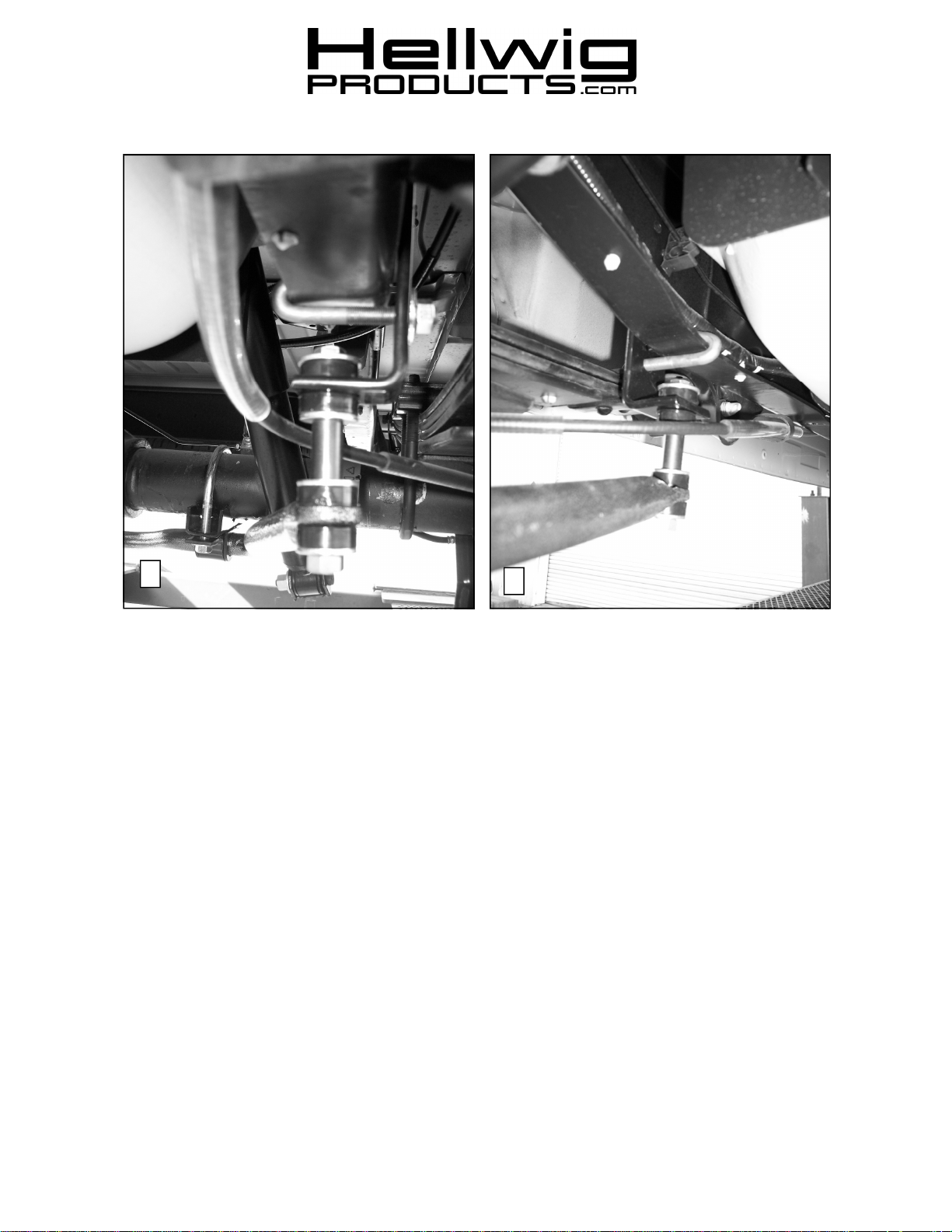
6. Attach J-bolts to frame and angle bracket as shown in photos (6) & (7) using thick washer and locknut. Leave loose for
adjustment later.
7. Align sway bar for best fit and end link orientation.
8. Tighten 1/2” fastener holding the angle bracket to frame rail to 50 ft-lb.
9. Tighten J-bolt to 20-25 ft-lb.
10. Tighten Locknuts on U-bolts to 35 ft-lb.
11. Tighten end links until bushings begin to bulge slightly. DO NOT OVERTIGHTEN.
12. Recheck your installation, looking for clearance on any undercarriage components, such as gas lines, exhaust pipes, brake
lines, wiring, differential cover, etc.
13. Drive vehicle for a few miles, then recheck for position and tightness, readjust and retorque as needed. Then recheck your
installation after one week of driving and every thirty (30) days thereafter.
ALL IMPORTANT NOTE CARDS, WARNING CARDS AND THE WARRANTY
FORM
7183 (R-7183)
02/06/2007
 Loading...