

Page 1
559-734-7451 800-367-5480 FAX 559-734-7460
INSTALLA TION INSTRUCTIONS
REAR STABILIZER BAR
Thank you for purchasing a quality Hellwig Product.
1 2
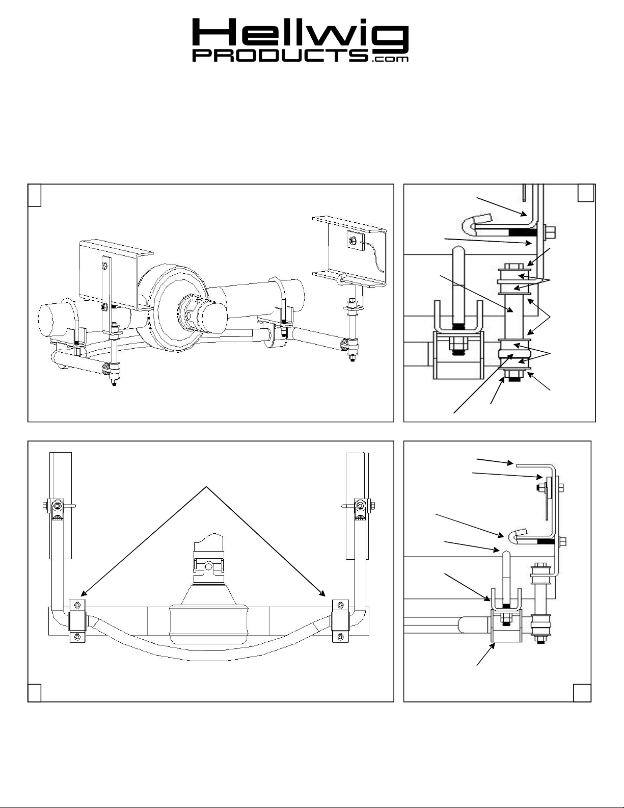
D-BUSHING & U-PLATE MOUNTING
LOCATIONS ON SWAY BAR & AXLE
VEHICLE’S FRAME
FRAME
BRACKET
METAL
SLEEVE
SWAY BAR
VEHICLES FRAME
THREADED PLATE
W/PIGTAIL
J-BOLT
WASHER
BUSHING
WASHER
BUSHING
WASHER
LOCK NUT
U-BOLT
SADDLE BRACKET
U-PLATE & D-BUSHING
BOTTOM VIEW
3 4
7085 ( R-323 ) 05/16/07
Page 2

559-734-7451 800-367-5480 FAX 559-734-7460
TORQUE TABLE
BOLT SIZE: 3/8” = 20-30 ft. lbs. – 7/16” = 35-45 ft. lbs. – ½” = 50-70 ft. lbs. – 9/16” = 70-90 ft. lbs.
SAFETY: BEFORE STARTING YOUR INSTALLATION, BE SURE TO SET PARKING BRAKE AND CHOCK
TIRES.
NOTE: TO EASE INSTALLATION AND TO PROPERLY ADJUST BAR, THE WEIGHT OF THE VEHICLE
MUST BE ON THE SUSPENSION, AS IF DRIVING DOWN THE ROAD.
DO NOT RAISE VEHICLE BY FRAME.
NOTE: THIS SWAY BAR IS DESIGNED TO MOUNT BELOW THE REAR AXLE WITH THE ARMS
TOWARDS THE FRONT OF THE VEHICLE.
1. Place the U-bolts over the axle tubes just to the inside of the lower shock mount brackets. Position
the U-bolts under the brake lines at the axle so no damage can occur when the U-bolts are tightened.
2. Place the sway bar under the axle tubes so that the flat areas of the bar are slightly rearward of the
axle. SEE PHOTO (3).
3. Position the D-bushings on the flat areas of the sway bar to line up with the U-bolts on the axle.
Place the U-plates over the bushings. Install the saddle brackets on axle U-bolts. Raise the sway bar
and attach the U-plates onto the U-bolts with mounting hardware provided. Leave loose at this time
to allow for adjustment later.
4. Locate the frame brackets. Install the end links on the short leg of the frame brackets as in photo (2)
end link , flat washer , end link bushing. Insert thru hole at the frame bracket , install bushing , flat
washer and steel; sleeve. Locate the pre-drilled holes on the vehicles frame in front of the rear axle
assy. Using the threaded plate w/pigtail attach the frame bracket from the outside with the short leg
pointing towards the drive line assy. Do the same to opposite side. Leave loose at this time to allow
adjustment later. SEE PHOTO (4).
5. Raise the sway bar arms up to the mounted frame brackets. Complete the end links assy, washer ,
bushing , sway bar, bushing, flat washer and lock nut. SEE PHOTO (2). Tighten just slightly that
the bushings start to bulge or damage can occur to the poly-bushings.
6. With the sway bar properly aligned, sway bar center at the axle and the end link assemblies straight
up and down as possible. Torque mounting hardware at the axle and vehicle’s frame to specified
rates. Check for clearance on all under carriage components, electrical wires, exhaust, shocks, brake
and fuel lines.
7. Test drive your vehicle re-check your installation re-adjust and tighten as needed. After one week of
driving re-check your installation. Re-check regularly on a monthly basis thereafter.
ATTENTION INSTALLER: BE SURE THAT THE CUSTOMER RECEIVES THIS INSTRUCTION
SHEET, ALL IMORTANT NOTE CARDS AND THE WARRANTY FORM
7085 ( R-323 ) 05/16/07
Page 3

559-734-7451 800-367-5480 FAX 559-734-7460
PARTS LIST
RSB KIT # 7085
PART # QTY DESCRIPTION
20218009 1 1-1/2” SWAY BA R
20907085 1 COMPLETION KIT
11 1000892 2 1-1/2” POLY BUSHING
20800787 2 U-PLATE
118020840 2 1/2” X 4” X 6-1/2” RND U-BOL T
20800761 2 SADDLE BRACKET
20800085 2 ANGLE FRAME BRACKET
20801929 2 THREADED PLTE W/PIGTAIL
101500204 2 1/2” X 8” END LINK
20800695 2 J-BOL T
125000039 1 SMALL PARTS BAG # BG-39
107521044 2 1/2” LOCK NUT
107401042 2 7/16” LOCK NUT
102400023 2 7/1 6” FLAT WASHER
101500125 2 1/2” X 1-1/2” CAP SCREW
105521044 8 1/2” HEX NUT
102520043 14 1/2” FLAT WASHER
120010610 2 5/8” X 2-7/8” END LINK SPACER
11 1000762 8 1/2” END LINK BUSHING
135000323 1 INSTRUCTION SHEET ( R-323 )
7085 ( R-323 ) 05/16/07
 Loading...