

Page 1
559-734-7451 800-367-5480 FAX 559-734-7460
INSTALLATION INSTRUCTIONS
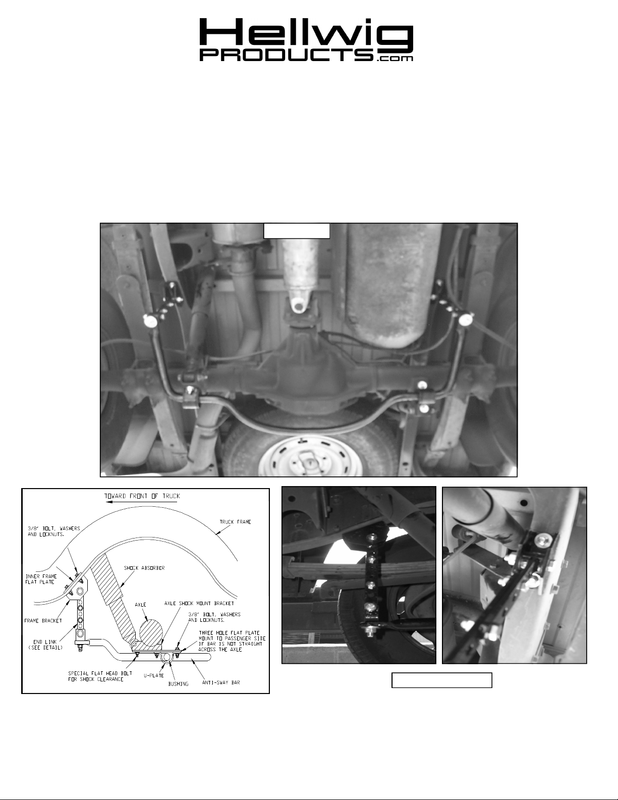
Rear Stabilizer Bar
94-02 DODGE 4X4 W1500-W3500 TRUCK
INCLUDING DUAL WHEELS
Thank you for purchasing a quality Hellwig Product.
REAR VIEW
PASSENGER SIDE
7626 ( (R 7626 ) 01/13/04
Page 2

ATTENTION INSTALLER: BE SURE THE CUSTOMER RECEIVES THIS INSTRUCTION SHEET, ALL
559-734-7451 800-367-5480 FAX 559-734-7460
TORQUE TABLE
BOLT SIZE: 3/8” = 20-30 ft. lbs. – 7/16” = 35-45 ft. lbs. – ½” = 50-70 ft. lbs. – 9/16” = 70-90 ft. lbs.
SAFETY: BEFORE STARTING YOUR INSTALLATION, BE SURE TO SET PARKING BRAKE AND CHOCK THE WHEELS.
NOTE: TO EASE INSTALLATION AND TO PROPERLY ADJUST BAR, THE WEIGHT OF THE VEHICLE MUST BE ON
THE SUSPENSION, AS IF DRIVING DOWN THE ROAD. DO NOT RAISE THE VEHICLE BY THE FRAME.
NOTE: THIS UNIT IS DESIGNED TO MOUNT TO THE BOTTOM OF THE AXLE SHOCK MOUNTS WITH THE ARMS OF
THE BAR FACING TOWARDS THE FRONT OF THE VEHICLE. IT WILL BE NECESSARY TO REMOVE THE BOTTOM OF
THE SHOCK FROM THE LOWER SHOCK MOUNTS. IT MAY ALSO BE NECESSARY TO DRILL TWO (2) HOLES IN THE
BOTTOM OF THE FRAME RAIL ON SOME VEHICLES.
NOTE: THIS KIT INCLUDES LOCKNUTS WHICH REQUIRE TIGHTENING WITH A WRENCH AFTER BEING STARTED
BY HAND
1. Install the D-shaped poly –bushings onto the bar on each side of the center hump. These bushings will
align with the shock mounts on the axle.
2. With the shocks removed from the lower axle mounts. Place the mounting bolts provided into the holes in
the bottom of the shock mounts so that the threads are pointing downward. The hole that is directly below
the shock will use the special clearance flat head bolt provided. The square shoulders under the bolt head
should press into the hole, which will not allow the bolt to turn.
3. As per diagram. There are two (2) three hole flat plates included in this kit, one (1) small and one (1) large.
.The small three hole plate mounts to the bottom of the passenger side shock mount so that the third hole is
to the rear of the axle. For vehicles with the Dana 80 rear axle use the large three (3) hole plate. This
will align the bar across the axle. Use the thick two (2) hole plate on the driver’s side to space the bar
downwards to be level with the passenger side.
4. Place the U-plates over the bushings on the bar and attach to the plates with hardware provided. Leave
loose at this time to allow for adjustment later.
5. Assemble the end-links by installing the sleeve type poly-bushing (it may be necessary to lightly grease
the poly-bushing and steel sleeve before installing) into the tube welded to the end of the link. Place the
small steel sleeve inside the bushing to complete this end of the assembly. See Diagram in instruction
sheet insert (R-344). Mount the small U-shaped bracket to the end of the bar. Then match up the holes in
the end-links to the length needed that will allow the arms of the bar to be as level with the frame as possible.
6. Rotate the bar so that the brackets contact the bottom of the frame. Align the end-links in as straight up and
down position as possible. The end-links will show the position where the frame brackets will contact the
bottom of the frame rails.
7. With the frame brackets up against the frame and the bar centered and all adjustments locating the bar under the vehicle properly. If your vehicle does not have the factory mounting holes. Mark the frame with the
centers of the frame bracket mounting holes and drill two (2) 7/16” holes in the bottom of each frame rail.
Be sure to move any wires or lines from inside the frame to avoid any possible damage.
8. Mount the frame brackets to the frame with hardware provided. Place the small flat two (2) hole plate inside the frame rail above the frame brackets. Torque all frame and axle mounting hardware to the specified
rates. Reinstall the shocks in their mounts and torque.
9. Bounce the vehicle and check for clearance on all carriage components, shocks, exhaust etc…….
Drive the vehicle for a short distance then recheck your installation and periodically thereafter.
WARNING AND NOTE CARDS AND THE WARRANTY FORM.
7626 ( R 7626 ) 01/13/04
Page 3

PARTS LIST
RSB KIT # 7626
“94-02” W1500-3500 DODGE INCLUDING DUALLY
PART # QTY DESCRIPTION
20217626 1 SWAY BAR
20800026 1 LARGE (3) HOLE PLATE BRACKET
20800870 2 U-PLATE
111000866 2 (1-1/8”) I.D. POLY-BUSHING
20800797 2 FRAME BRACKET
20800789 2 CLEVIS BRACKET
20800774 4 WELDED END-LINK
20801865 2 FLAT PLATE
20800829 1 (3) HOLE PLATE (SMALL)
20800008 1 CROSS BAR
125000853 1 SLEEVE BUSHING BAG # BG-853
111000853 8 POLY BUSHING
20800722 4 STEEL SLEEVE
125020126 1 SMALL PARTS BAG # BG-126
101500018 2 (3/8” X 1-1/4”) ELEVATOR BOLT
107521044 2 (1/2”) LOCK NUT
101500124 2 (1/2” X 1-1/2”) CAP SCREW
102520043 2 (1/2”) FLAT WASHER
101500185 4 (7/16” X 2-1/4”) CAP SCREW
101500008 4 (3/8 X 1”) CAP SCREW
107401042 4 (7/16”) LOCK NUT
101500072 8 (3/8” X 1-1/4”) CAP SCREW
107302003 14 (3/8”) LOCK NUT
102320049 18 (3/8”) FLAT WASHER
13500 344 1 R-344 INSTRUCTION SHEET INSERT
135007626 1 R-7626 INSTRUCTION SHEET
*= FOR SHOCK MOUNT PROBLEMS ON W2500 AND W3500 TRUCKS USE KIT # PL-833
**== SOME DRILLING MAY BE REQUIRED
***= OLD SYTLE END-LINKS=
(2) EL-851 (7/16” X 5”) OR EL-796 (7/16” X 8”)
(2) SP-712 (1/2” X 2-1/2”) OR SP -794 (1/2” X 5”)
(1) BG-782 & BG-315
 Loading...