

559-734-7451 800-367-5480 FAX 559-734-7460
INSTALLATION INSTRUCTIONS
7252 Rear Stabilizer Bar
Thank you for purchasing a quality Hellwig Product.
PLEASE READ THIS INSTRUCTION SHEET COMPLETELY BEFORE STARTING YOUR INSTALLATION
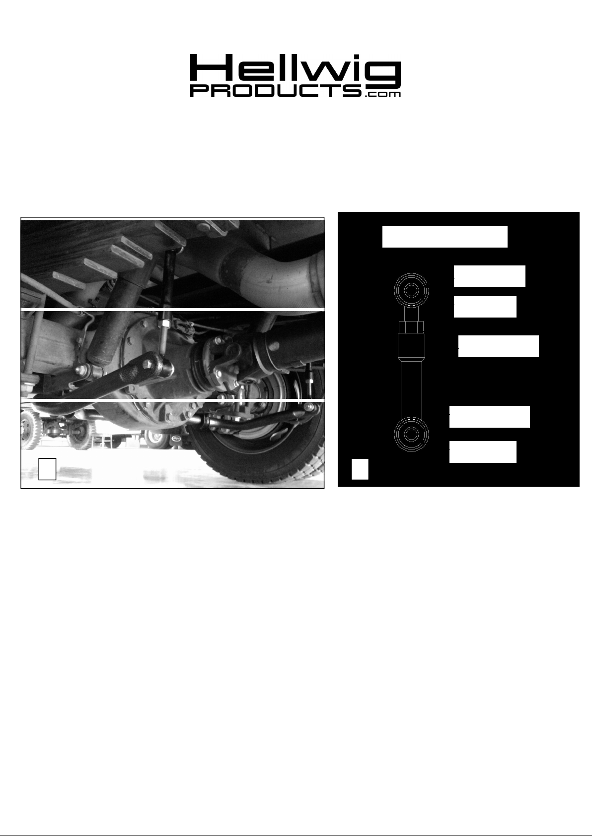
End LinkAssembly
Bushing
Sleeve
9/16-18 Nut
1/2” ID Sleeve
Bushing
21
SAFETY: BEFORE STARTINGYOURINSTALLATION,BE SURE TO SET PARKING BRAKE AND CHOCK TIRES.
NOTE: TO EASE INSTALLATION AND TO PROPERLY ADJUST BAR, THE WEIGHT OF THE VEHICLE MUST BE
ON THE SUSPENSION,AS IF DRIVING DOWN THE ROAD. DO NOT RAISE VEHICLE BY FRAME.
NOTE: THIS UNIT IS DESIGNED TO REPLACE THE FACTORY REAR SWAY BAR.
1. Remove factory installed sway bar and end links.
2. Assemble end links as shown in diagram 2 with the large sleeves in the female end of the end link.
3. Attach end links to frame rail as shown using the 1/2” X 2-1/2” bolts washers and nuts. Torque to 50-60 ft-lb
4. Loosely attach end of sway bar to end links with 7/16” x 2-3/4” bolts, washers and locknuts. Leave loose at this time.
5. Lubricate bushings and attach to sway bar in location of sway bar mounts on axle.
6. Attach sway bar to axle with supplied 3/8” bolts, washers and locknuts. The washers are only installed on the back side of
the shock brackets—not on the u-plates. Torque to 25 ft-lb.
7. Torque end link bolts on sway bar to 35 ft-lb.
8. Recheck your installation, looking for clearance on any undercarriage components, such as gas lines, exhaust pipes, brake
lines, wiring, differential cover, etc.
9. Drive vehicle for a few miles, then recheck for position and tightness, readjust and retorque as needed. Then recheck
periodically thereafter.
ATTENTION INSTALLER: PLEASE MAKE SURE CUSTOMER RECEIVES THIS INSTRUCTION SHEET,
ALL IMPORTANT NOTE CARDS, WARNING CARDS AND THE WARRANTY
7252 (R-7252) 11/19/2010
 Loading...