

Page 1
559-734-7451 800-367-5480 FAX 559-734-7460
INSTALLATION INSTRUCTIONS
REAR STABILIZER BAR
82-02 CAMARO & FIREBIRD
Thank you for purchasing a quality Hellwig Product.
PLEASE READ THISINSTRUCTION SHEETCOMPLETELY BEFORE STARTINGYOUR INSTALLATION
1
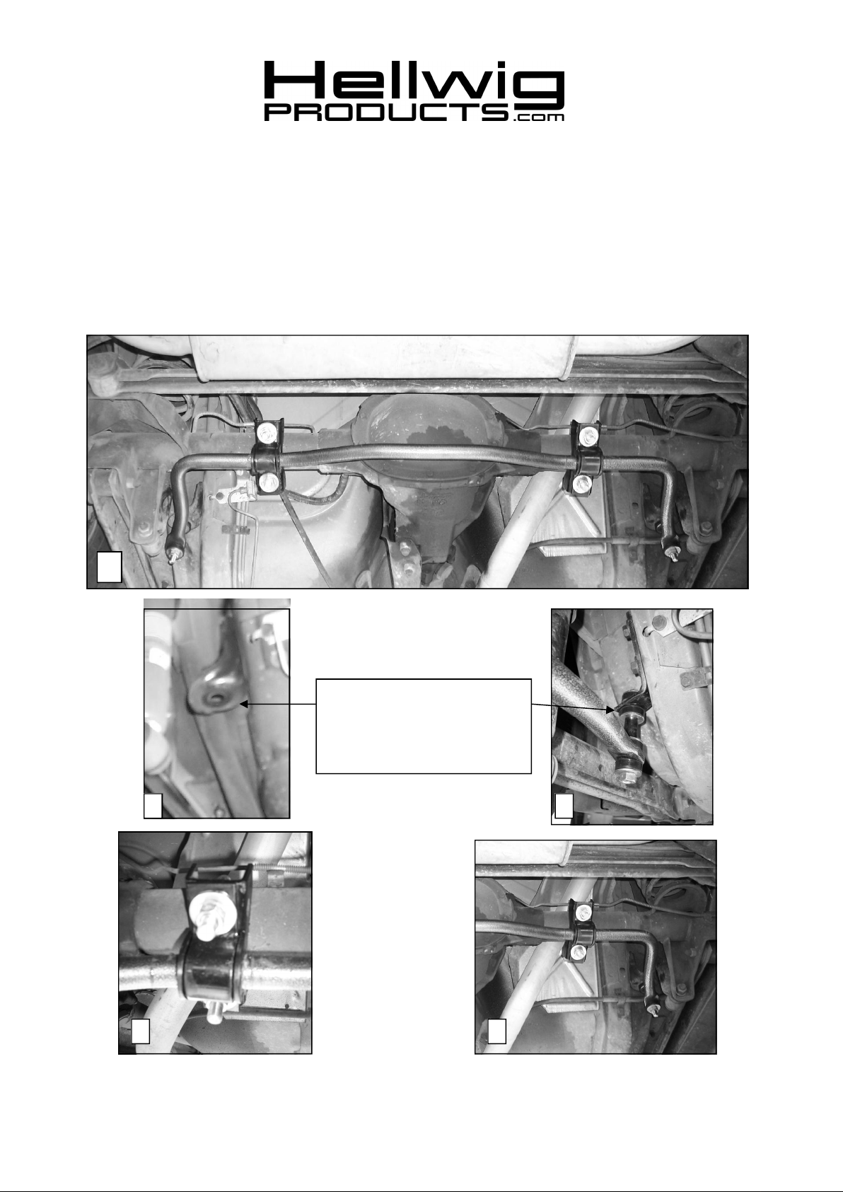
NOTE: THE FRAME BRACKETS
WILL BE MOUNTED FORWARD
OF THE AXLE POINTING TO
THE WHEELS ON BOTH SIDES
OF THE VEHICLE.
2 3
4 5
5801 ( R-5801 ) 02/11/04
Page 2

559-734-7451 800-367-5480 FAX 559-734-7460
TORQUE TABLE
BOLT SIZE: 3/8” = 20-30 ft. lbs. – 7/16” = 35-45 ft. lbs. – ½” = 50-70 ft. lbs. – 9/16” = 70-90 ft. lbs.-5/8”=120 ft. lbs
SAFETY: BEFORE STARTING YOUR INSTALLATION, BE SURE TO SET PARKING BRAKE AND CHOCK
TIRES.
NOTE: THIS UNIT IS DESIGNED TO REPLACE THE FACTORY INSTALLED REAR ANTI-SWAY BAR. OR AS
AN ADDITION IF THE VEHICLE WAS NOT EQUIPPED WITH A FACTORY REAR SWAY BAR.
NOTE: THISKIT INCLUDES LOCKNUTS WHICH REQUIRE TIGHTENING WITH A WRENCH AFETR BE
ING STARTED BY HAND.
NOTE:THIS SWAY BAR WILL MOUNT UNDER THE DIFFERENTIAL WITH THE ARMS FACING TOWARDS
THE FRONT OF THE VEHICLE.
1. Install the D-shaped poly bushings on the sway bar as close as possible to the bend on the
arms of the sway bar. SEE PHOTO ONE (1).
2. Install the U-bolts on the vehicles rear axle. SEE PHOTOS FOUR (4) AND FIVE (5).
Make sure that the U-bolt is under the brake line on the axle as not to crush the brake line
when the U-bolts are tightened.
3. Position the saddle brackets over the U-bolts on the axle. If vehicle was equipped with a
factory installed sway bar, use factory saddles. Install the U-plates over the D-bushings
using the mounting hardware provided. Leave loose at this time at this time to allow for
adjustment.
4. Locate the two predrilled holes on the outside of the frames. These holes will be between
the upper shock mounts and the forward trailing arms. Use the self tapping bolts provided
and install the left and right brackets. Tighten down completely. SEE PHOTOS TWO (2)
AND THREE (3). If equipped with factory installed sway bar, re-use factory frame brackets.
5. Install the end link bushings on the end links and attach to the left and right frame brackets
that were mounted.
6. Raise the arms of the sway bar up to the end links. Finish your assembly of the end links.
SEE PHOTOS FOUR (4) AND FIVE (5). Tighten so that the bushings start to bulge. Do
not over tighten.
7. Center the sway bar and the end links.
8. Torque the axle U-bolt lock nuts to 25-30 ft-lb.
9. Bounce the vehicle. Check for clearance on all undercarriage components. Recheck your
installation - check for clearance on wires, exhaust, fuel and brake lines.
10. After one week of driving check your installation. Recheck on a monthly regular basis
thereafter.
ATTENTION INSTALLER: BE SURE THAT THE CUSTOMER RECEIVES THIS INSTRUC
TION SHEET, ALL IMORTANT NOTE CARDS AND THE
WARRANTY FORM
5801 ( R-5801 ) 02/11/04
Page 3

559-734-7451 800-367-5480 FAX 559-734-7460
PARTS LIST
RSB KIT # 5801
“82-02” CAMARO & FIREBIRD
PART # QTY DESCRIPTION
21205801 1 1” SWAY BAR
20905801 1 COMPLETION KIT #-5801
21800773 1 RIGHT HAND ANGLE BRACKET
21800772 1 LEFT HAND ANGLE BRACKET
111000409 2 1” POLY BUSHING
20800430 2 U-PLATE
20800871 2 SADDLE BRACKET
118020480 2 1/2” X 3” X 4-1/4” ROUND U-BOLT
101500010 2 7/16” X 4-1/2” CAP SCREW
111000786 2 1” MINI POLY BUSHING
20800822 2 U-PLATE ( MINI POLY BUSHING )
125030336 1 BUSHING BAG # BG-336
111000389 8 END LINK BUSHING
125020239 1 SMALL PARTS BAG # BG-239
102420041 8 7/16” FLAT WASHER
102520043 4 1/2” FLAT WASHER
107401042 2 7/16" LOCK NUT
107521044 4 1/2" LOCK NUT
101500031 4 10 X 25MM SELF TAPPING MACHINE SCREW
20800723 2 1/2” X 1-1/4” END LINK SPACER
135005801 1 INSTRUCTION SHEET R-5801 (R-286)
5801 ( R-5801 ) 02/11/04
 Loading...