

559-734-7451 800-367-5480 FAX 559-734-7460
INSTALLATION INSTRUCTIONS
FRONT STABILIZER BAR
2003+ GMC KODIAK 4500/5500
Thank you for purchasing a quality Hellwig Product.
PLEASE READ THIS INSTRUCTION SHEET
COMPLETELY BEFORE STARTING YOUR INSTALLATION
SAFETY: BEFORE STARTING YOURINSTALLATION, BE SURE TO SET PARKING BRAKE AND
CHOCK THE TIRES.
NOTE: THIS SWAY BAR IS TO BE MOUNTED ON THE FRONT OF THE FORWARD AXLE WITH
THE HUMP POINTING TOWARDS THE GROUND, AND THE ARMS POINTING TOWARDS
THE FRONT OF THE VEHICLE.
NOTE: THIS KIT INCLUDES LOCKNUTS WHICH REQUIRE TIGHTENING WITH A WRENCH
AFTER BEING STARTED BY HAND.
TORQUE TABLE
BOLT SIZE: 3/8” = 20-30 ft. lbs. – 7/16” = 35-45 ft. lbs. – ½” = 50-70 ft. lbs. – 9/16” = 70-90 ft. lbs.
1. Remove nuts from the axle u-bolts located on the forward side of the front axle. Do not remove nuts
from u-bolts on rearward side of axle.
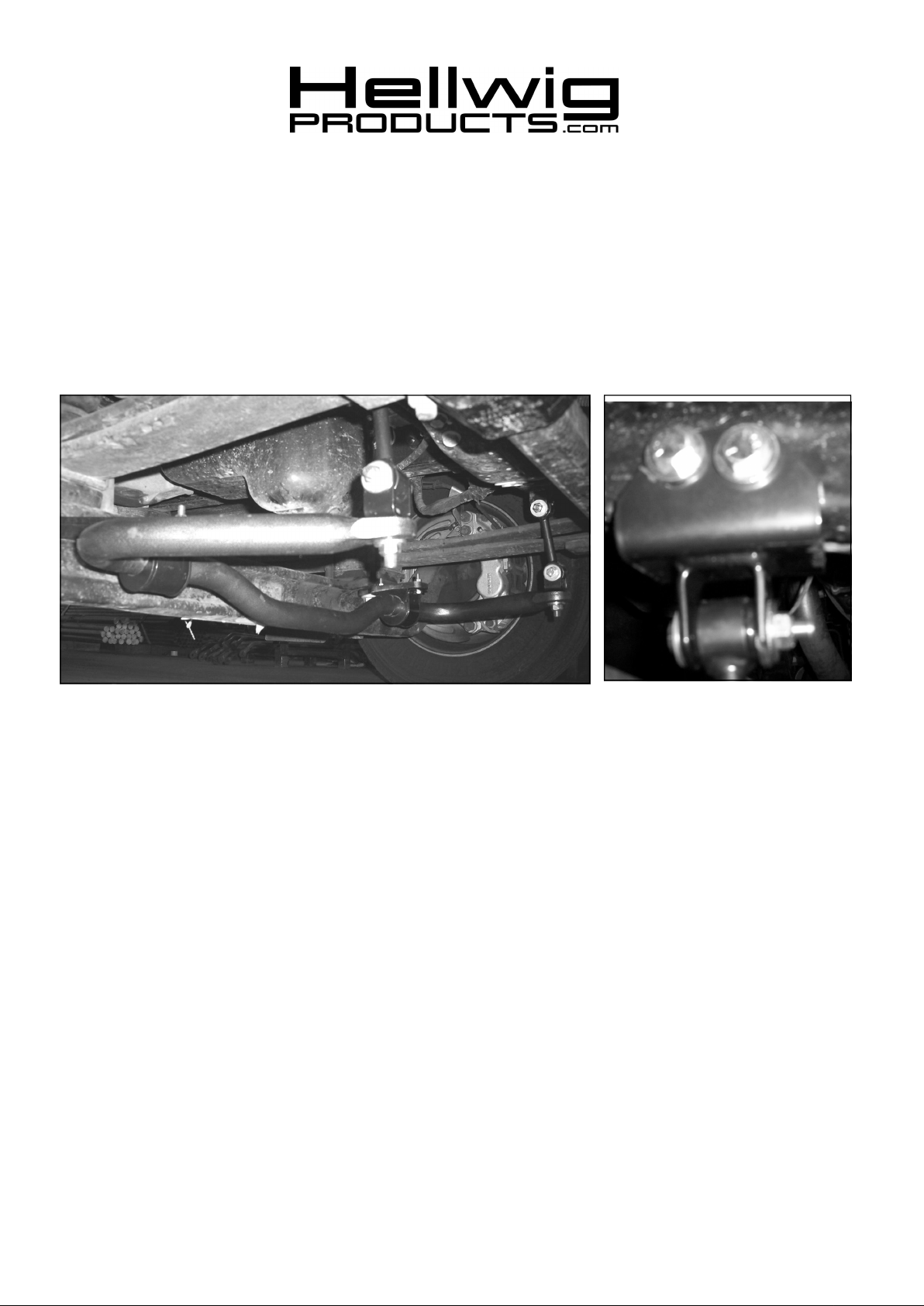
2. Attach frame brackets to existing holes in frame crossmember using the 1/2X4-1/2” bolts, washers, and
locknuts as shown in photos. Orient brackets so that the clevis sits perpendicular to the ground and
torque bolts to 60 ft-lb.
7243 ( R-7243) 10/08/2007
559-734-7451 800-367-5480 FAX 559-734-7460
3. Install the axle plates on the axle as shown in photos by inserting legs of u-bolts through the holes
in the mounting plates. Install mounting plates with the bushing mounting surfaces inboard of the
leaf springs. Make sure the plates sit squarely against the axle mounting surface. Re-install nuts
and torque to factory specification.
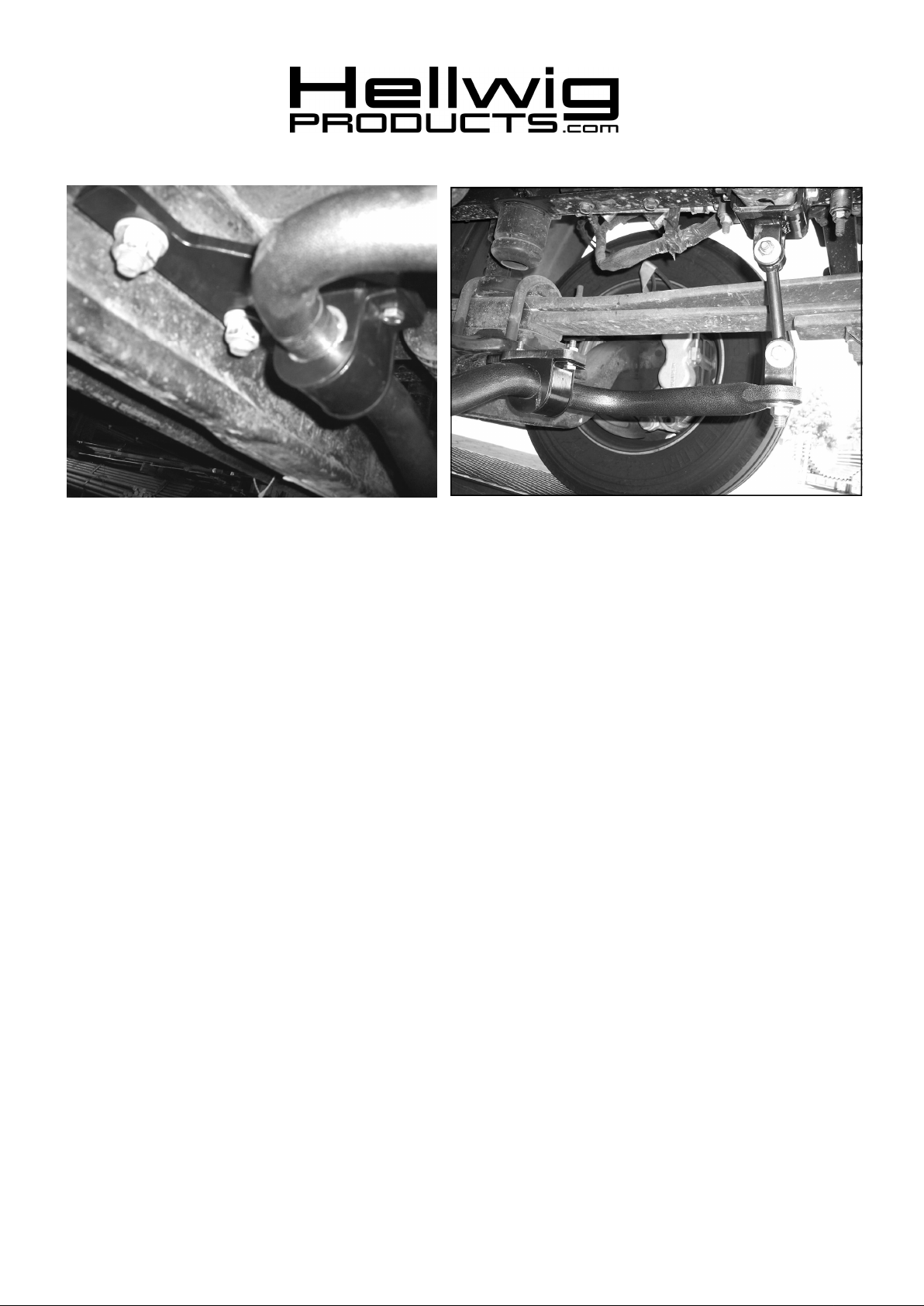
4. Assemble end links by inserting hourglass bushing first and then inner sleeve into the each loop of
the end link. Fully lubricate bushings and sleeves before installation.
5. Attach end links to clevis of frame brackets using 7/16X2-3/4” bolts, washers, and locknuts as
shown in photos. Leave loose for adjustment later.
6. Lubricate the D-bushings and place on sway bar in approximate mounting location of the axle
brackets.
7. Raise sway bar upward to so that the bushings contact the mounting surface on the axle plates and
attach swaybar using the u-plates and the 3/8X1-1/4” bolts, washers, and locknuts. Install bolts
with threaded portion pointing upwards as shown in photo. Leave loose for adjustment later.
8. Attach clevis to sway bar end as shown in photo with 1/2-2” bolt, washer and locknut. Do not
place washer under bolt head. Align clevis so that it will mate to end link when installed. Torque
to 80 ft-lb.
9. Rotate sway bar and attach each clevis on end of sway bar to an end link using 7/16-2-3/4” bolts,
washers, and locknuts. Leave loose for adjustment later.
10. Align the sway bar under the vehicle to be as centered as possible and so that the end links are as
even from side to side as possible. The end links will allow a wide range of pivot and do not need
to be straight up and down front to rear.
11. When bar is centered, tighten the 3/8” bolts on axle plates to 30-35 ft-lb and tighten the 7/16” end
link bolts to 55-60 ft-lb.
12. Check for clearance on all undercarriage components etc. shocks, spare tire, fuel tank, exhaust,
brake and fuel lines. Test drive the vehicle and recheck your installation readjust in needed. After
one week of driving recheck your installation. Recheck on a monthly regular basis thereafter.
ATTENTION INSTALLER: BE SURE THAT THE CUSTOMER RECEIVES THIS INSTRUCTION SHEET,
ALL IMORTANT NOTE CARDS AND THE WARRANTY FORM
7243 ( R-7243) 10/08/2007
 Loading...