

Hellwig 6805 User Manual
559-734-7451 800-367-5480 FAX 559-734-7460
INSTALLA TION INSTRUCTIONS
Rear Stabilizer Bar
2005+ MUSTANG
Thank you for purchasing a quality Hellwig Product.
1
2 3 4
6805 ( R-6805 ) 07/22/05

559-734-7451 800-367-5480 FAX 559-734-7460
TORQUE TABLE
BOLT SIZE: 3/8” = 20-30 ft. lbs. – 7/16” = 35-45 ft. lbs. – ½” = 50-70 ft. lbs. – 9/16” = 70-90 ft. lbs.
SAFETY: BEFORE STARTING YOUR INSTALLATION, BE SURE TO SET PARKING BRAKE AND
CHOCK THE WHEELS.
NOTE: TO EASE INSTALLATION AND TO PROPERLY ADJUST BAR, THE WEIGHT OF THE VEHI-
CLE MUST BE ON THE SUSPENSION, AS IF DRIVING DOWN THE ROAD. DO NOT RAISE THE
VEHICLE BY FRAME.
NOTE: THIS UNIT IS DESIGNED TO REPLACE THE FACTORY MOUNTED SWAY BAR OR AS A RE-
PLACEMENT IF YOUR VEHICLE IS NOT EQUIPPED WITH A FACTORY MOUNTED SWAY
BAR.
NOTE: THIS KIT INCLUDES LOCK NUTS WHICH REQUIRE TIGHTENING WITH A WRENCH AFTER
BEING STARTED BY HAND.
1. Remove the factory mounted sway bar from the vehicle if equipped.
2. Lubricate the bore of the D-shaped poly bushings with the supplied lubricant.
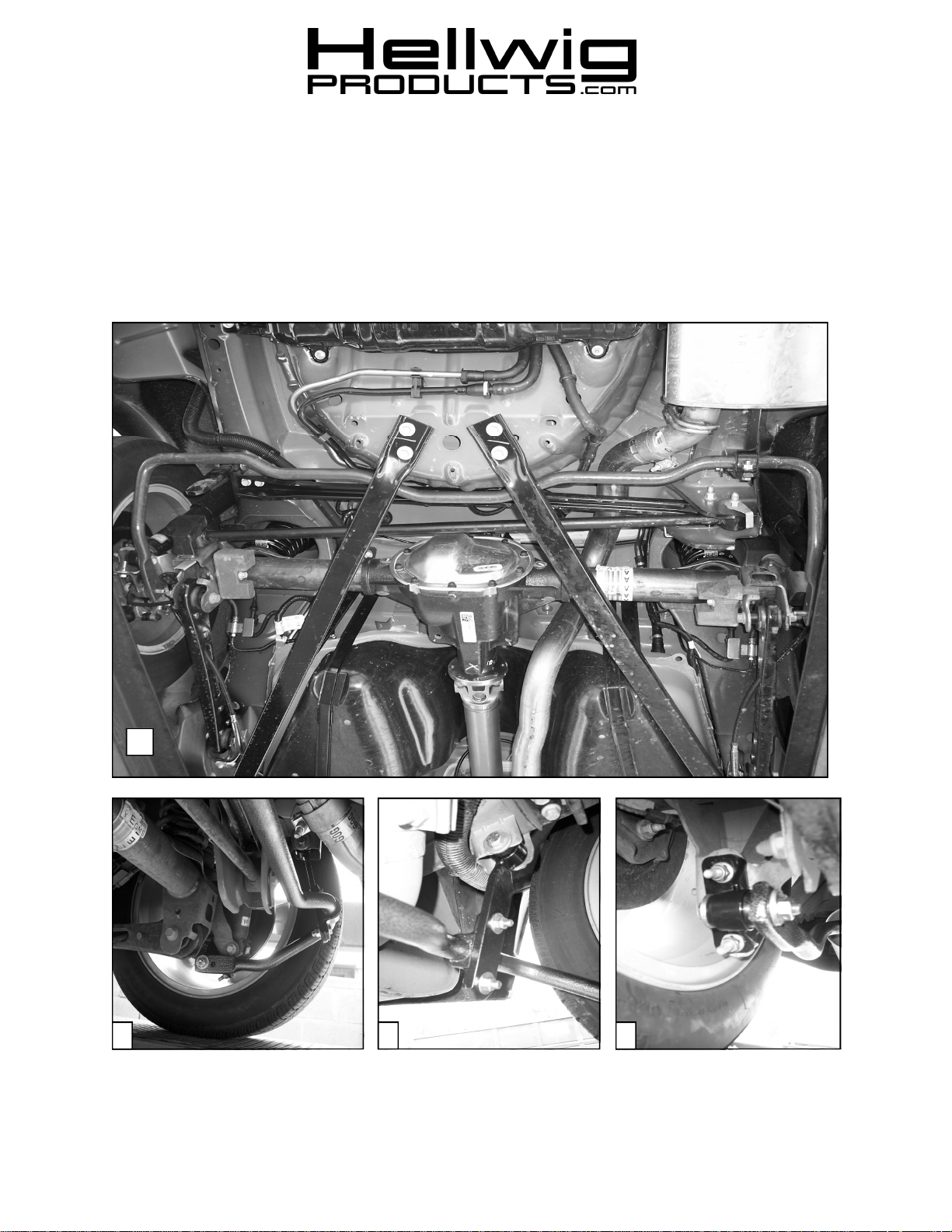
3. Locate and position the D-shaped poly bushings on the new rear sway bar in as close a position as the
factory sway bar mounting points. SEE PHOTO ONE ( 1 ).
4. Assemble the sway bar hanger brackets. Install the hourglass shaped bushings with the 3/4” ID hole on
the looped ends of the hanger brackets. Insert the 3/4” OD metal sleeve through the center of the bushings. (This sleeve does not have a seam) Lightly grease the bushing and sleeve to ease installation.
Install the hanger brackets on the factory mounting points using the 1/2” X 2-1/2” bolts, locknuts and
large diameter washers provided. ( SEE PHOTOS TWO (2) AND THREE ( 3). Leave loose to allow
for adjustment later.
5. Locate the two axle brackets and install the hourglass shaped bushings with the 5/8” ID hole. Insert
the 1.38” long metal sleeve through the center of the bushings. (This sleeve has a seam in it) Lightly
grease the bushing and sleeve to ease installation. Attach the brackets to the lower shock mount
brackets using the factory hardware. ( SEE PHOTO FOUR ( 4 ). If the vehicle did not have a factory
rear sway bar, use the 3/8” bolts, locknuts, and large diameter 3/8” washers supplied to attach the axle
brackets.
6. Raise the sway bar into position and attach the D-shaped poly bushings to the hanger brackets, using
the U-plates, 3/8” bolts, locknuts, and small diameter 3/8” washers.
7. Raise the arms of the sway bar and attach to the axle brackets using the 7/16 x 3” bolts, locknuts, and
thick washers. For initial installation, attach bar to the axle brackets using the hole closest to the end of
the arm of the sway bar. It may be necessary to place a thick washer between the bushing and the arm
of the sway bar if there is a gap. Two thick washers have been included in the kit for this purpose.
Leave loose to allow for adjust ment later.
8. With the sway bar properly aligned torque all the mounting bolts to the specified rates. Check for clearance for electrical wires, brake lines or cables, fuel lines, and any other chassis component.
9. Test drive your vehicle recheck your installation re-adjust and re-torque if necessary. Recheck on a
monthly regular basis thereafter.
10. The sway bars arms have two mounting holes. Mounting the sway bar on the outer hole is the
nominal position. For a firmer setting, use the inner hole. We recommend starting with the
outer mounting hole as in photo ( 1 ) until you are accustomed to the vehicles new handling characteristics. Select the mounting point that best fits your driving style.
ATTENTION INSTALLER: BE SURE THAT THE CUSTOMER RECEIVES THIS INSTRUCTION
SHEET, ALL IMORTANT NOTE CARDS AND THE WARRANTY FORM
6805 ( R-6805 ) 07/22/05
 Loading...