

Page 1

559-734-7451 800-367-5480 FAX 559-734-7460
INSTALLATION INSTRUCTIONS
4885 Single Cab Control Compressor Kit
Thank you for purchasing a quality Hellwig Product.
PLEASE READ THIS INSTRUCTION SHEET COMPLETELY BEFORE STARTING
YOUR INSTALLATION
IMPORTANT NOTES
DO NOT INFLATE ANYAIR SPRINGASSEMBLYUNLESS IT HAS BEEN
PROPERLY INSTALLED ON VEHICLE.
DO NOT INFLATE AIR SPRINGS OVER 100 PSI
AMINIMUM OF 5-10 PSI MUST BE MAINTAINED IN AIR SPRINGS
AFTER INSTALLATION FOR WARRANTYTO BE VALID. FAILURE TO
KEEPMINIMUM PRESSURE INAIR SPRINGS WILLVOID WARRANTY.
THIS UNIT IS DESIGNED TO INCREASETHE LEVEL LOAD CARRYING
CAPACITY OFYOUR VEHICLE. NEVER LOAD THE VEHICLE THIS
UNIT IS INSTALLED ON BEYOND THE MANUFACTURER’S MAXIMUM
GROSS VEHICLE WEIGHT RATING.
OVERINFLATIONAND IMPROPER USE MAY RESULT IN PERSONAL
INJURYAND/OR DAMAGE TO YOUR VEHICLEAND PROPERTY.
IMPORTANT NOTE: IF COMPRESSOR KIT IS NOT SUPPLIEDWITH
THE BRAIDEDAIR HOSE USEA90 DEGREE ANGLED FITTINGAND
SYNFLEXAIR LINE TO COMPLETE ASSEMBLY.
4885 ( R-4885) 03/09/07
Page 2

559-734-7451 800-367-5480 FAX 559-734-7460
INSTALLATION INSTRUCTIONS
4885 Single Cab Control Compressor Kit
Thank you for purchasing a quality Hellwig Product.
PLEASE READ THIS INSTRUCTION SHEET COMPLETELY BEFORE STARTING
YOUR INSTALLATION
IMPORTANT NOTES
DO NOT INFLATE ANYAIR SPRINGASSEMBLY UNLESS IT HAS BEEN
PROPERLY INSTALLED ON VEHICLE.
DO NOT INFLATE AIR SPRINGS OVER 100 PSI
AMINIMUM OF 5-10 PSI MUST BE MAINTAINED IN AIR SPRINGS
AFTER INSTALLATION FOR WARRANTYTO BE VALID. FAILURE TO
KEEPMINIMUM PRESSURE INAIR SPRINGS WILLVOID WARRANTY.
THIS UNIT IS DESIGNED TO INCREASETHE LEVEL LOAD CARRYING
CAPACITY OFYOUR VEHICLE. NEVER LOAD THE VEHICLE THIS
UNIT IS INSTALLED ON BEYOND THE MANUFACTURER’S MAXIMUM
GROSS VEHICLE WEIGHT RATING.
OVERINFLATIONAND IMPROPER USE MAY RESULT IN PERSONAL
INJURYAND/OR DAMAGE TO YOUR VEHICLEAND PROPERTY.
4885 ( R-4885) 03/09/07
Page 3
559-734-7451 800-367-5480 FAX 559-734-7460
BEFORE STARTINGYOUR PROJECT
WHEN LIFTING A VEHICLE WITH A JACK, BE SURE TO SET THE PARKING BRAKE AND USE SAFETY STANDS.
ENSURE THAT THE INSTALLATION OF COMPONENTS WILL NOT CRUSH OR DAMAGE FUEL AND BRAKE
LINES OR ELECTRICAL HARNESSES.
BEFORE DRILLING ANY HOLES, ENSURE THAT ALL ELECTRICAL WIRES, FUEL LINES, BRAKE LINES, BRAKE
HOSES AND ANY OTHER COMPONENTS ARE MOVED OR PROTECTED TO AVOID DAMAGE FROM DRILLING
ANY HOLES .
DO NOT ATTEMPT ANY MODIFICATIONS TO THE VEHICLE OTHER THAN THOSE OUTLINED IN THIS
INSTRUCTION SHEET. IF ANY INTERFERENCE WITH THE GAS TANK, FUEL LINES, BRAKE LINES, EXHAUST
PIPE, ETC. EXISTS, STOP YOUR INSTALLATION AND CALL HELLWIG PRODUCTS FOR TECHNICALHELP.
IF WHEELS ARE REMOVED FOR INSTALLATION OF KIT, CHECK MANUFACTURERS SPECIFICATIONS FOR
PROPER LUG NUT TORQUE BEFORE REINSTALLING WHEELS.
WHEN CUTTING AIR BRAKE TUBING, A SQUARE CUT IS REQUIREDANDTHEHOSE END MUST NOT BE
DEFORMED OR LEAKAGE MAY RESULT. IF DEFORMATIONOF THE HOSE END OCCURS, THE HOSE END
MUST BE REWORKED SO THAT IT IS ROUND.
ENGAGEMENTOF THE SEALING O-RING WILL BE FELT WHEN THE AIR LINE HASBEEN INSERTED
PROPERLY INTO THE FITTING. FITTINGS MAY BE DISCONNECTED IF REQUIRED BY PUSHING DOWN ON THE
OUTER RING WHILE PULLING FIRMLY ON THE AIR LINE.
ROUTE AIR LINES AWAY FROM EXHAUST PIPES OR ANY OTHER SOURCES OF HEAT AND ENSURE THAT THE
AIR LINES ARE PROTECTED FROM SHARP EDGES.
4885 ( R-4885) 03/09/07
Page 4
559-734-7451 800-367-5480 FAX 559-734-7460
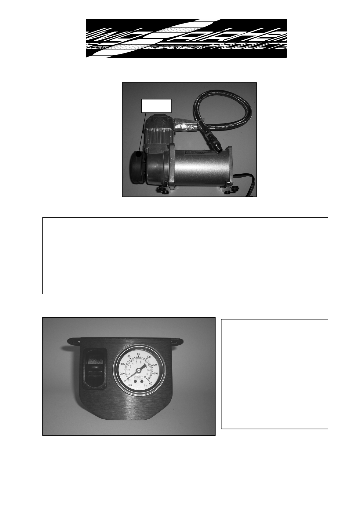
Air Filter
1. Prepare the compressor for mounting by HAND-TIGHTENING the air filter
into the port on the compressor. Select a convenient mounting location for the
compressor where it will be protected from moisture and debris but has enough
air flow to keep the compressor from overheating. Mount compressor using provided hardware.
2. Select a location under the
dash for mounting the dash/
gauge control panel. Use the
control panel as a template to
mark mounting holes before
drilling 3/16 diameter holes
for the mounting hardware.
Mount dash control panel using supplied hardware.
4885 ( R-4885) 03/09/07
Page 5
559-734-7451 800-367-5480 FAX 559-734-7460
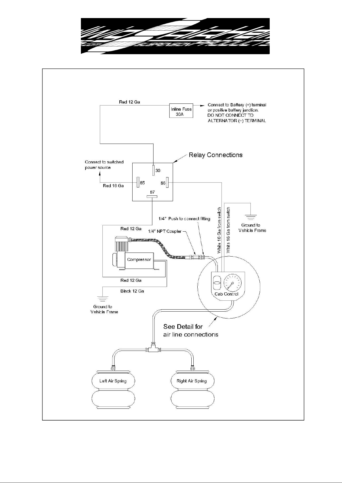
Plumbing and Wiring Diagram
4885 ( R-4885) 03/09/07
Page 6
559-734-7451 800-367-5480 FAX 559-734-7460
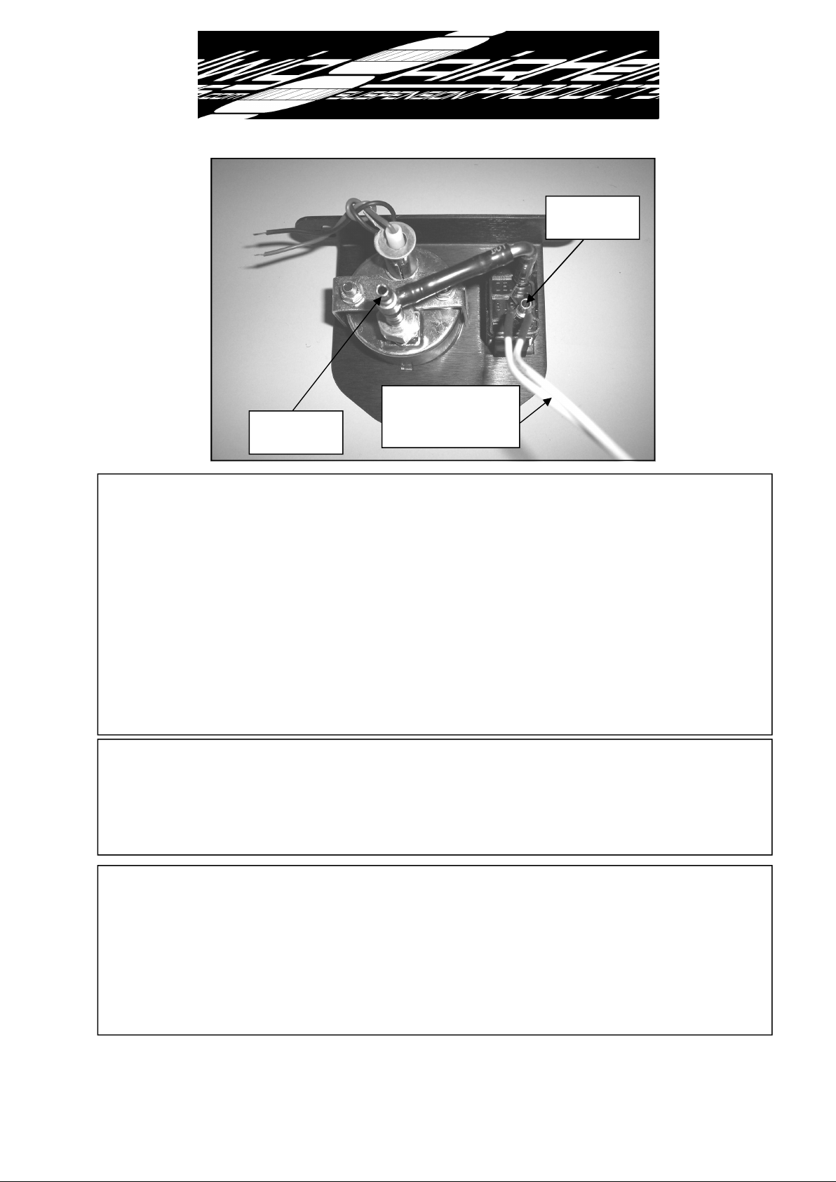
Connect to
Compressor
Connect white wires
Connect to
Air Springs
as shown in electrical
& plumbing diagram.
3. Follow plumbing and wiring diagram for connection of dash control, compressor, and
relay. See photo above for connections to barbed fittings on dash control. Connect white
wires on back of switch as shown in plumbing and wiring diagram. Either white wire can
be the ground connection as long as the other wire is connected to the relay as shown in
the diagram. The supplied 1/4” nylon tube is designed to slip tightly over the barbed fittings and will not require any additional clamps. If you need to remove a hose from the
barbed fitting, carefully cut the tubing so as not contact the fitting. If the fitting is damaged or nicked a leak may develop. Take care when routing air and electrical lines that
they will not be crimped or chafed during installation or use. Deviation from the electrical
diagram and failure to use an inline fuse holder (supplied) will void warranty. DO NOT
install fuse in inline fuse holder until all connections and circuits are verified to be completed correctly.
4. After all connections have been verified, install fuse in inline fuse holder, apply park
brake and start engine with shifter in park or neutral. The compressor should turn on
when the dash switch is pushed up. Due to the amperage draw of the compressor, failure
to turn engine on during initial startup may drain the battery enough to require a jump
start.
5. Test system by adding air to air springs. Pushing up on the paddle switch will add air
to the system and pushing down will exhaust air. Fill air springs to 40 psi and check all
connections with soapy water for leaks. After the integrity of the system is verified, the
air springs can be inflated to desired pressure. A MINIMUM OF 5-10 PSI MUST BE
MAINTAINED IN AIR SPRINGS AFTER INSTALLATION FOR WARRANTY
TO BE VALID. FAILURE TO KEEP MINIMUM PRESSURE IN AIR SPRINGS
WILL VOID WARRANTY.
4885 ( R-4885) 03/09/07
 Loading...