

Page 1
559-734-7451 800-367-5480 FAX 559-734-7460
INSTALLATION INSTRUCTIONS
Front Stabilizer Bar
1955-1957 Chevrolet Full Size
Thank you for purchasing a quality Hellwig Product.
5721(R-5721) 01/15/07
Page 2
559-734-7451 800-367-5480 FAX 559-734-7460
TORQUE TABLE
Bolt Size 3/8”— 35 ft lbs * Bolt Size 7/16”— 45 ft lbs* Bolt Size 1/2”—75 ft lbs *Bolt Size 9/16”— 90 ft lbs
SAFETY: BEFORE BEGINNING INSTALLATION BE SURE TO SET THE PARKING BRAKE AND
CHOCK THE WHEELS.
NOTE: TO EASE INSTALLATION AND PROPERLY ADJUST THE BAR, THE WEIGHT OF THE
VEHICLE MUST BE ON THE SUSPENSION AS IF DRIVING DOWN THE ROAD. DO NOT RAISE
THE VEHICLE BY THE FRAME.
NOTE: THIS KIT REQUIRES DRILLING THE FRAME RAIL AND LOWER CONTROL ARMS. INSTALLER MUST ENSURE BAR WILL INSTALL CORRECTLY
BEFORE DRILLING ANY HOLES.
1. Place the D shaped bushings onto the straight areas of the bar on each side of the center hump as close to the
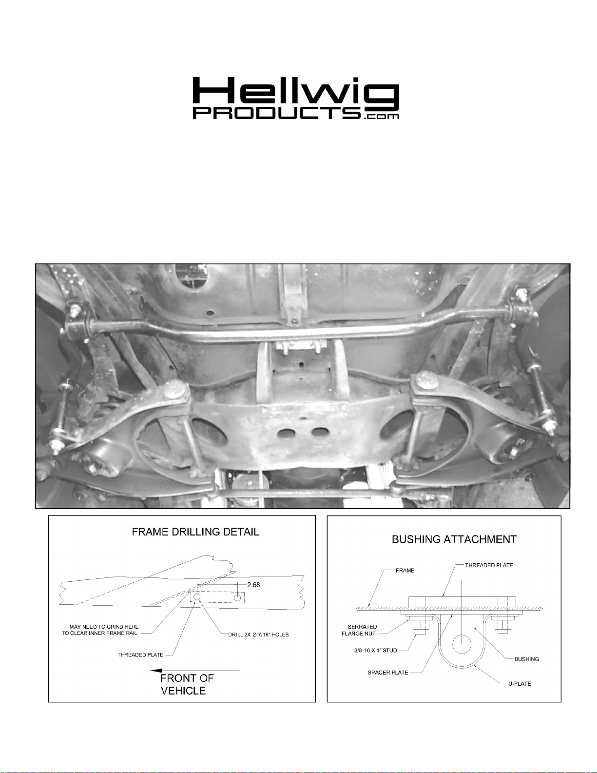
outside bend as possible as shown in photo on page 1. Install U-plates on D-bushings.
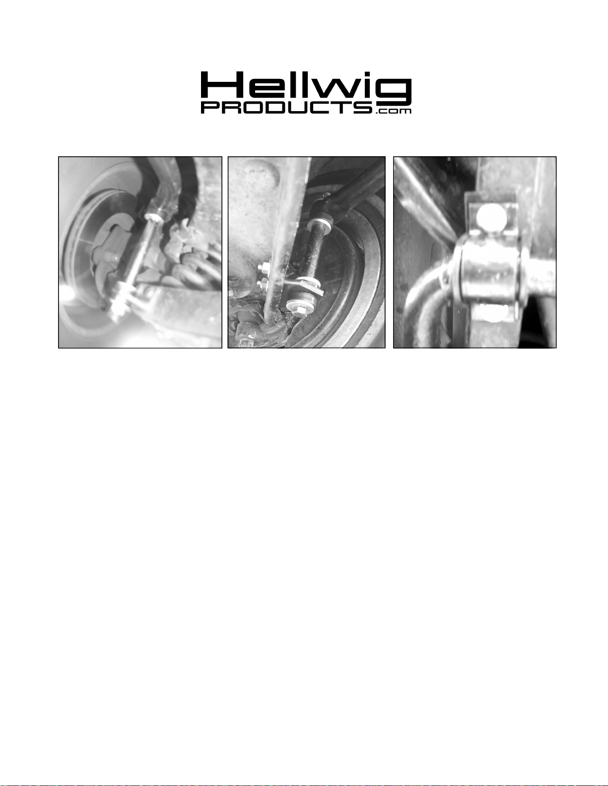
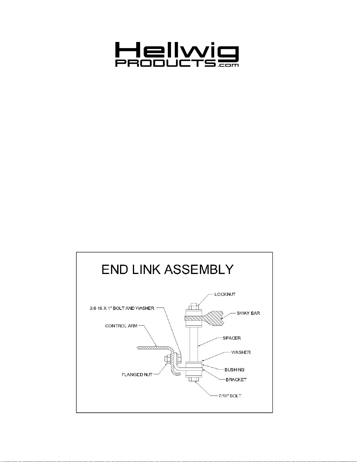
2. Pre-assemble end links, bushings, and control arm mounting brackets to sway bar as shown in photos.
3. Using a floor jack or other means to hold sway bar in position, raise sway bar up to frame rail and align
sway bar so that the control arm mounting brackets contact the control arms when the end links are vertical.
Align sway bar for best fit. Make sure the sway bar will not interfere with the frame or any components as it
rotates.
4. Align U-plates with frame rail. On 1955 and 1956 models, keep in mind that the inner frame rail section can
cause interference with the threaded plate so it is best to note installation of threaded plate when locating Uplates. It may be necessary to grind a corner of the threaded plate to allow best alignment of U-plates.
5. When satisfied with fit, mark holes on frame rails for U-Plates. Use threaded plate as a guide for hole spacing. Check clearance of threaded plate to inner frame before drilling holes. .
6. Drill two 7/16” holes in each frame rail.
7. Attach U-plates to frame rail with 3/8-16 X 1” studs and serrated flange nuts as shown in diagram on page 1.
Leave loose for adjustment later.
5721(R-5721) 01/15/07
Page 3
559-734-7451 800-367-5480 FAX 559-734-7460
8. Align end links and end link mounting brackets on control arm so that end links are as vertical as possible.
9. When satisfied with fit, mark holes on control arms for mounting brackets and drill two 13/32” holes in
each control arm.
10. Attach end link mounting brackets to control arm using 3/8-16 X 1” bolts and serrated flange nuts.
11. Align sway bar and end links and tighten 3/8” mounting bolts to 25 ft-lb.
12. Tighten locknut on end of end link until bushings start to bulge slightly.
13. Bounce the vehicle checking for clearance on all under carriage components. Test drive the
vehicle and recheck all clearances and the installation alignment. Adjust as needed. Re-check your installation after one week of driving and periodically on a regular basis.
5721(R-5721) 01/15/07
Page 4

THREADED PLATE BRACKET
1/8” POLY BUSHING
3/4” END LINK SPACER
559-734-7451 800-367-5480 FAX 559-734-7460
PARTS LIST
FSB # 5721
PART # QTY DESCRIPTION
21205721 1 1-1/8” SWAY BAR
20905721 1 COMPLETION KIT #-5721
20800785 2 U-PLATE
20800025 2
111000486 2 1 101500157 2 7/16” X 6” CAP SCREW
20800041 2 ANGLE BRACKET
20801865 2 FLAT PLATE BRACKET
125030336 1 BUSHING BAG # BG-336
111000389 8 END LINK BUSHING
125020002 1 SMALL PARTS BAG # BG-002
20800812 2 1/2” X 2 102420041 8 7/16” FLAT WASHER
101509001 4 3/8-16 X 1” THREADED STUD
102306001 4 3/8" FLAT WASHER
107302030 8 3/8" LOCK NUT
101500008 4 3/8” X 1” CAP SCREW
107401042 2 7/16" LOCK NUT
135005721 1 INSTRUCTION SHEET R-5721
5721(R-5721) 01/15/07
 Loading...