

Page 1
559-734-7451 800-367-5480 FAX 559-734-7460
INSTALLATION INSTRUCTIONS
Rear Stabilizer Bar 5817
1982-2002 Camaro, Firebird
Thank you for purchasing a quality Hellwig Product.
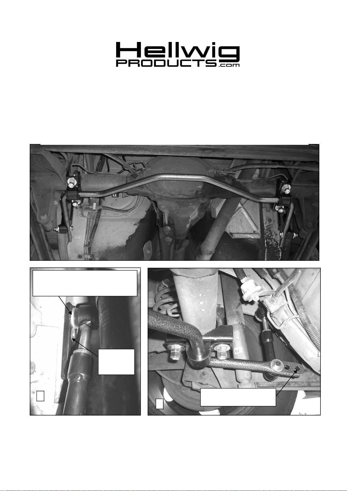
Washer between frame bracket and bushing. Applyred loc-tite to bolt and torque
to 40 ft-lb
Torque flat
head bolts to
20-25 ft-lb
2
Attach end link to outermost
hole for initial use.
3
5817 (R-5817) 05/05/2008
Page 2
559-734-7451 800-367-5480 FAX 559-734-7460
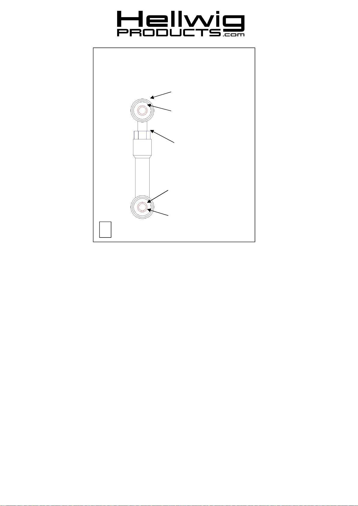
End LinkAssembly
Bushing
Sleeve
9/16-18 Nut
Sleeve
Bushing
3
TORQUE TABLE
Bolt Size 3/8”— 35 ft lbs * Bolt Size 7/16”— 45 ft lbs* Bolt Size 1/2”—75 ft lbs *Bolt Size 9/16”— 90 ft lbs
SAFETY: BEFORE BEGINNING INSTALLATION BE SURE TO SET THE PARKING BRAKE AND CHOCK THE
WHEELS.
NOTE: TO EASE INSTALLATION AND PROPERLY ADJUST THE BAR, THE WEIGHT OF THE VEHICLE MUST BE
ON THE SUSPENSION AS IF DRIVING DOWN THE ROAD. DO NOT RAISE THE VEHICLE BY THE FRAME.
NOTE: THIS KIT MAY REQUIRE RELOCATION OF FUEL AND BRAKE LINES. INSTALLER
MUST ENSURE THAT THE SWAY BAR KIT WILL NOT INTERFERE WITH ANY FUEL OR
BRAKE LINES OR HOSES.
1. If equipped, remove factory installed rear sway bar and all mounting brackets.
2. Lubricate the D shaped bushings and place them onto the straight areas of the bar on each side of the
center hump as close to the outside bend as possible.
3. Hold bar up to the axle and locate the position on the axle tubes to mount the u-bolts. Be sure to put the
U-Bolts Under Any Brake Lines, Wires or Hoses on the Axle to Avoid Any Possible Damage. The
threads of the U-Bolts will point down.
5817 (R-5817) 05/05/2008
Page 3

559-734-7451 800-367-5480 FAX 559-734-7460
3. Place the saddle brackets onto the U-Bolts on the axle tubes. Place the U-Plates over the D shaped bushings on the bar and attach the bar to the U-Bolts and saddle brackets with the flat washers and nuts provided. LEAVE LOOSE AT THIS TIME to allow for adjustment later.
4. Position sway bar on axle so that it clears all frame mounted components including fuel tanks, brake
lines, fuel lines, etc. Sway bar can be rotated back and forth on axle to maximize clearance.
5. Assemble end links by inserting bushings and inner sleeve into outer sleeve of end link. Fully lubricate
bushings before installation. Install 9/16” nut on threaded section of end link before assembling the two
halves together as shown.
6. Attach frame bracket to subframe with M10-1.5x30 flat head bolts in the captured nuts used to attach
the factory bracket to the subframe. See photo 2.
6. Attach end link to frame bracket using the 7/16 X 2” grade 8 bolt with a washer between the bushing
and frame bracket. Apply red loc-tite to the threads of the bolt and torque to 40 ft-lb. See photo 2.
7. Attach end links to the outermost hole using the 7/16 X 2-3/4” grade 8 bolt and locknut. Adjust end
links so that the arms of the sway bar are as level as possible.
8. After adjustment tighten the 7/16” bolt and locknut to 35-40 ft-lb. Tighten the 9/16” nut on end links to
60 ft-lb.
9. Tighten axle U-bolts to 30-35 ft-lb.
10. Bounce the vehicle checking for clearance on all under carriage components: fuel tank, shocks, differential, brake and fuel lines, etc. Test drive the vehicle and recheck all clearances and the installation alignment. Adjust as needed. Re-check your installation after one week of driving and periodically on a regular basis.
11.The sway bars arms have three mounting holes. Mounting the sway bar on the outer hole
(forward-most) is the nominal position. For a firmer setting, use the inner holes. We recommend starting with the outer mounting hole until you are accustomed to the vehicles new handling characteristics. Select the mounting point that best fits your driving style.
ATTENTION INSTALLER: BE SURE THAT THE CUSTOMER RECEIVES THIS INSTRUCTION SHEET,
ALL IMORTANT NOTE CARDS AND THE WARRANTY FORM
5817 (R-5817) 05/05/2008
 Loading...