


559-734-7451 800-367-5480 FAX 559-734-7460
INSTALLATION INSTRUCTIONS
Thank you for purchasing a quality Hellwig Product.
PLEASE READ THIS INSTRUCTION SHEET COMPLETELY BEFORE STARTING YOUR INSTALLATION PROCEDURES.
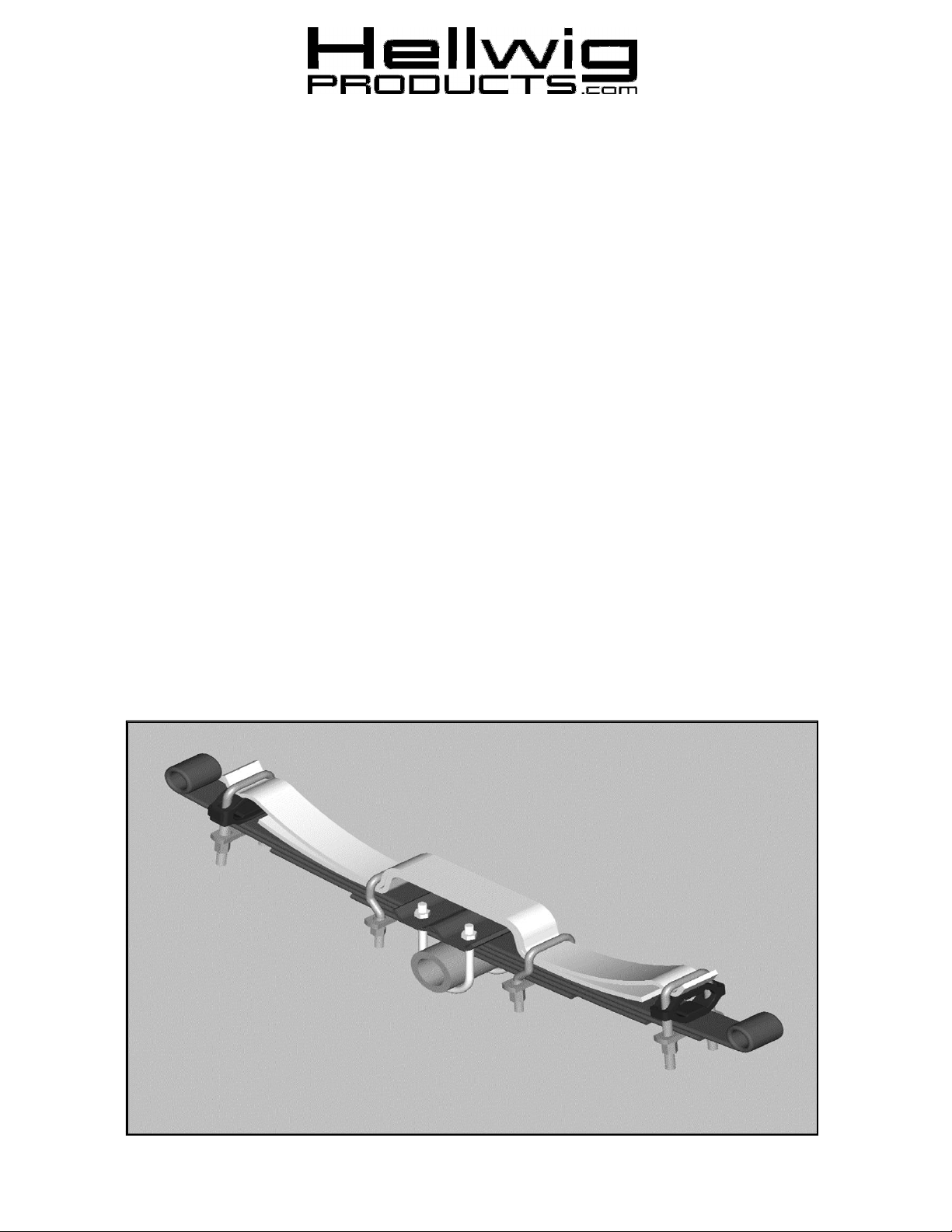
Hat Section
Straight U-bolt
Silencer Bushing
Leaf Stack
Main Leaf
Second Leaf
Crossbars
Main Spring
Offset U-bolts
Leaf Tip
TORQUE TABLE
BOLT SIZE: 3/8” = 20-30 ft. lbs. – 7/16” = 35-45 ft. lbs. – 1/2” = 50-70 ft. lbs. – 9/16” = 70-90 ft. lbs
SAFETY:
PARK YOUR VEHICLE ON A FLAT LEVEL SURFACE, SET THE PARKING BRAKE AND CHOCK THE FRONT TIRES.
NOTES:
1. THIS KIT INCLUDES LOCKNUTS WHICH REQUIRE TIGHTENING WITH A WRENCH AFETR BEING STARTED BY HAND.
2. IF YOUR VEHICLE IS EQUIPPED WITH A BRAKE FLUID PROPORTIONING VALVE ON THE REAR AXLE READ INSERT
(R-362)
3. YOUR SPRING MAY HAVE A SMALL HOLE IN THE END. THIS IS FOR OUR MANUFACTURING PROCESS AND WILL NOT
BE USED.
4. IF YOUR VEHICLE IS EQUIPPED WITH A FACTORY CONTACT OVERLOAD IT MUST BE REMOVED BEFORE
INSTALLING THE NEW HELPER SPRINGS
5.
HELLWIG HELPER SPRINGS ARE DESIGNED TO INCREASE THE “LEVEL LOAD” CARRYING CAPACITY OF YOUR
VEHICLE. NEVER LOAD THE VEHICLE THAT THIS UNIT IS INSTALLED ON BEYOND THE MANUFACTURER’S
MAXIMUM GROSS VEHICLE WEIGHT RATING.
For installations on a Ford F150, tighten the front leaf tip U-bolt until the gap in the polyurethane silencer bushing
is fully compressed.
1. Lay out the spring leaves into two (2) sets. Each will consist of a main leaf with u-bolt cups and a second leaf
without cups. Lay the leaves so that the long ends are all in the same direction. Stack the leaves so that the
main leaf is on top. The long end of the spring stack must be installed toward the rear of the vehicle and the
short end toward the front.
2. Place the spring stack on top of the main spring with the long end toward the rear of the vehicle.
3. Place the U-bolts with the straight legs in the cups at the ends of the spring with the silencer bushing between
the main spring and the helper spring as shown in the diagram. Loosely install the crossbars using the
hardware provided.
4. Adjust the crossbars on the end of the springs so that the adjacent leaf tip will not make contact with the
crossbar when the spring is deflected. It may be necessary to move the spring stack fore or aft for best
alignment.
009 ( R-009) 2/26/2013
559-734-7451 800-367-5480 FAX 559-734-7460
5. Install the offset U-bolts with the offset toward the axle as shown in the diagram. The U-bolt should be fastened as
close to the hat section as possible. If you are working on 2-1/2” wide springs position the outboard U-bolt leg
against the outboard edge of the main spring to maximize brake hose, caliper, and backing plate clearance. The Ubolts may also be installed with the legs pointing up and crossbars on top of spring to provide additional clearance
if required. Install the crossbar with the washers and nuts to connect to the main spring. Torque the nuts to 65 ftlb and double nut.
6. Adjust the U-bolts at the end to desired preload. The minimum tension adjustment is having enough tension on the
end U-bolts so that they do not loosen or rattle and move when the vehicle is driven over rough or bumpy surfaces.
Maximum adjustment is when the leaf cups have been deflected two (2) inches from their free state. DO NOT
EXCEED THE MAXIMUM ADJUSTMENT OF 2 INCHES.
7. When adjustment is complete, double nut to lock in adjustment.
8. Check your installation for clearance on all undercarriage components; wires, fuel, brake, and air conditioning
lines. Test drive the vehicle and recheck your installation, adjust as needed. Recheck on a monthly basis thereafter.
ATTENTION INSTALLER:
BE SURE THAT THE CUSTOMER RECEIVES THIS INSTRUCTION SHEET, ALL
IMPORTANT NOTE CARDS AND THE WARRANTY FORM
Maintenance and Inspection:
Your Hellwig Suspension Product is built to last. However, as with all vehicle systems, it requires routine
inspection. Inspect your Hellwig installation looking for secure hardware and tight fitting brackets and bushings. If you do not perform this inspection, have your professional mechanic inspect as described.
009 ( R-009) 2/26/2013
 Loading...