

559-734-7451 800-367-5480 FAX 559-734-7460
INSTALLATION INSTRUCTIONS
Thank you for purchasing a quality Hellwig Product.
PLEASE READ THIS INSTRUCTION SHEET COMPLETELY BEFORE STARTING YOUR INSTALLATIONPROCEDURES.
TORQUE TABLE
BOLT SIZE: 3/8” = 20-30 ft. lbs. – 7/16” = 35-45 ft. lbs. – ½” = 50-70 ft. lbs. – 9/16” = 70-90 ft. lbs
SAFETY:
NOTE:
HAND.
NOTE:
INSERT (R-362)
PARK YOUR VEHICLE ON A FLAT LEVEL SURFACE, SET THE PARKING AND CHOCK THE FRONT TIRES.
THIS KIT INCLUDES LOCKNUTS WHICH REQUIRE TIGHTENING WITH A WRENCH AFTER BEING STARTED BY
IF YOUR VEHICLE IS EQUIPPED WITH A BRAKE FLUID PROPORTIONING VALVE ON THE REAR AXLE READ
NOTE: Your spring may have a small hole in the end, this is for our manufacturing process and will not be used.
IMPORTANT NOTE
CAPACITY OF YOUR VEHICLE. NEVER LOAD THE VEHICLE THAT THIS UNIT IS INSTALLED ON BEYOND THE
MANUFACTURER’S MAXIMUM GROSS VEHICLE WEIGHT RATING.
: HELLWIG HELPER SPRINGS ARE DESIGNED TO INCREASE THE “LEVEL LOAD” CARRYING
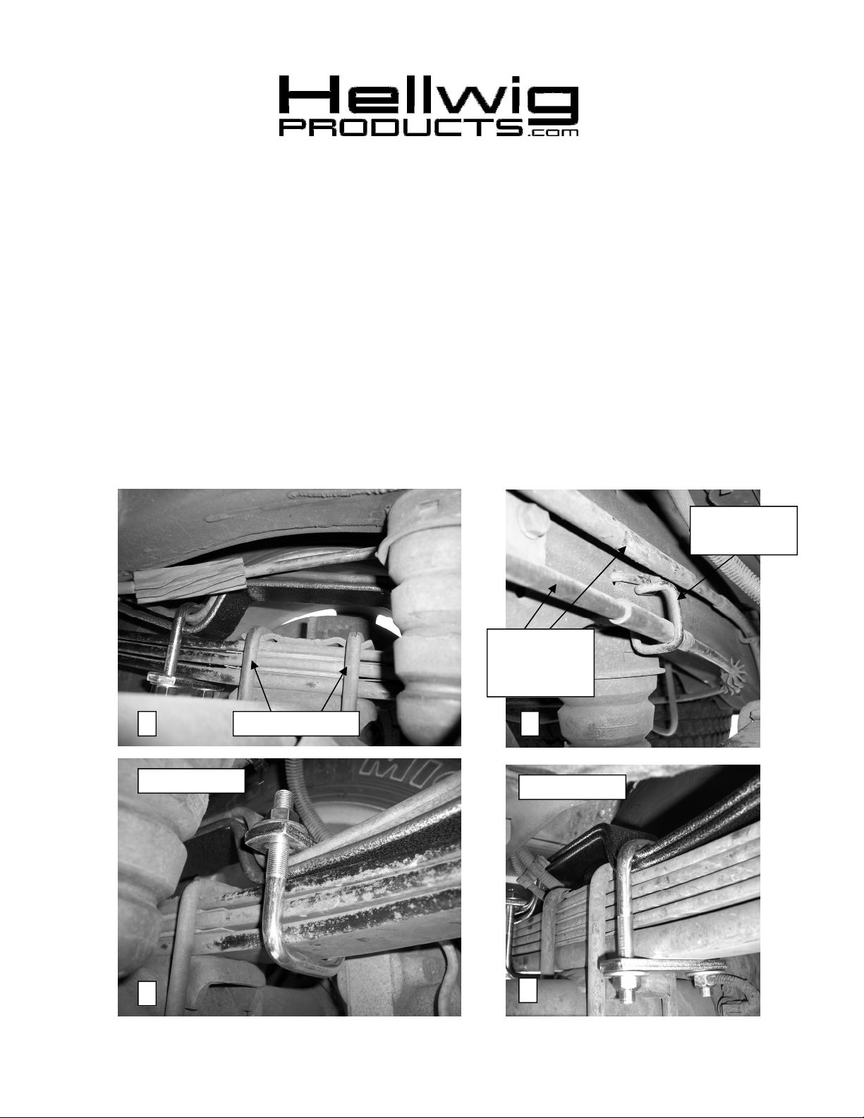
Remove this
Bracket
Zip Tie
These Lines
Together
1 2
Factory U-Bolts
Front Hump
3
4
Rear Hump
( R-610) 07/16/2012
559-734-7451 800-367-5480 FAX 559-734-7460
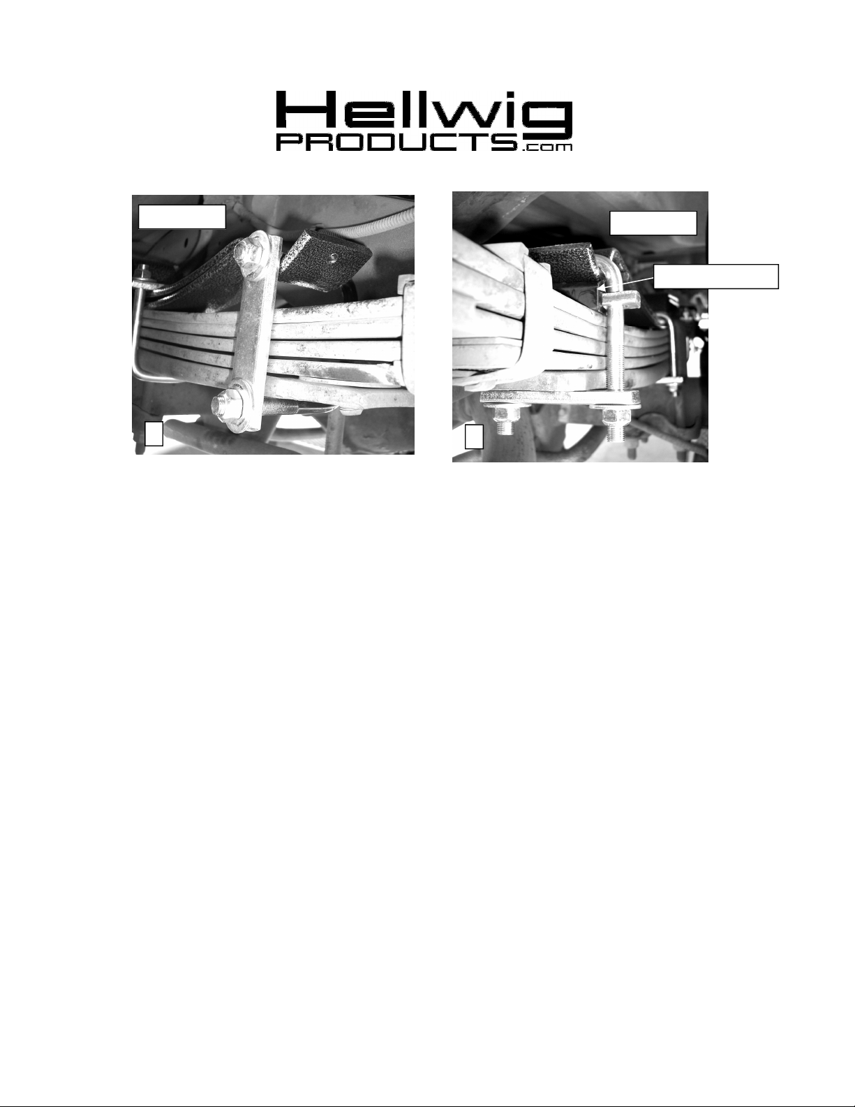
Front Cup
Rear Cup
House Bushing
5
1. Jack up the vehicle by the frame to allow the suspension to extend, making sure the e-brake is on, the tires are
chocked and the frame is supported by jack stands.
2. Remove the bracket holding the emergency brake cable just over the bump stop as shown in Photo 2. Zip tie
the lower brake cable to the upper one to keep it from drooping down.
3. Lay out the spring leaves into two (2) sets with the longer spring with the cups on top.
2. Place the spring on top of the main spring with the long end toward the rear of the vehicle and the hump
straddling the factory U-bolts as shown in Photo 1.
3. On the forward side of the center hump, install the 2.5” wide U-bolt with the legs up as shown in Photo 3 and
use the 1/2” stover nuts and washers to hold the cross bar across the top. Adjust the spring and crossbar
backwards and forwards to maximize clearance between the crossbar and the brake lines.
4. On the rearward side of the center hump, install the 2.5” wide U-bolt with the legs down as shown in Photo 4
and use the 1/2” stover nuts and washers to hold the cross bar across the bottom.
5. Check clearance between the spring and the underside of the vehicle. The spring can be moved slightly
backwards or forwards to maximize clearance.
6. Torque both of these to 50-75 ft-lbs.
7. On the forward cup, install the 3.5” wide U-bolt sideways with the legs facing out towards the tire. Secure in
place with the black, 2 hole plate, 1/2” stover nuts and washers as shown in Photo 5. Note: It may be necessary
to flex the spring tip down with a C-clamp to slide the U-bolt into position.
8. Slide the house shaped bushing over the 1” wide cross bar.
9. On the rear cup, install the 2.5” wide U-bolt with the legs facing down and the crossbar with the bushing in
between the spring cup and factory spring pack. Secure in place with the cross bar, 1/2” stover nuts and
washers as shown in Photo 6. Tighten the spring down until there is pressure on the bushing.
10. Lower vehicle to the ground and check your installation for clearance on all undercarriage components; wires,
fuel, brake, and air conditioning lines. Test drive the vehicle and recheck your installation, adjust as needed.
Recheck on a monthly basis thereafter.
6
INSTALLER: MAKE SURE THE OWNER RECEIVES THIS INSTRUCTION SHEET ALONG WITH
ALL IMPORTANT NOTES AND WARRANTY CARDS.
( R-610) 07/16/2012
 Loading...