


Signature 1.5
Two Channel Amplifier
T E C H N I C A L M A N U A L
Harman Consumer Group
250 Crossways Park Drive
Woodbury, N.Y. 11797
1-800 645-7484 in the USA
A Harman International Company
Part No.: 1112-SIGNATURE1.5 Rev A 7/99

Two Channel Amplifier |
Harman Kardon |
SIGNATURE 1.5 |
TABLE OF CONTENTS
SPECIFICATIONS.................................................................... |
1 |
Signature 1.5 FRONT PANEL CONTROLS............................ |
2 |
FEATURES .............................................................................. |
2 |
REAR PANEL CONNECTIONS............................................... |
3 |
INSTALLATION........................................................................ |
4 |
OPERATION ............................................................................ |
6 |
IDLE CURRENT ADJUSTMENT FOR SIGNATURE 1.5....... |
6 |
OUTPUT TRANSISTOR REPLACEMENT .............................. |
6 |
ON THE SIGNATURE 1.5 |
|
TROUBLE SHOOTING ............................................................ |
7 |
PROTECT MODE .................................................................... |
7 |
Signature 1.5 MECHANICAL EXPLODED VIEW.................... |
8 |
Signature 1.5 MECHANICAL PARTS LIST............................. |
9 |
Signature 1.5 PACKING EXPLODED VIEW ........................... |
9 |
|
Signature 1.5 POWER SWITCH/INDICATOR PCBs ............. |
10 |
|
Signature 1.5 POWER AMPLIFIER PCB Rev B.................... |
11 |
|
Signature 1.5 Electrical Parts List .......................................... |
12 |
|
Signature 1.5 (120V) TRANSFORMER WIRING Rev A........ |
14 |
|
Signature 1.5 (120V) TRANSFORMER WIRING Rev B........ |
15 |
|
Signature 1.5 (230V) TRANSFORMER WIRING Rev A........ |
16 |
|
Signature 1.5 (230V) TRANSFORMER WIRING Rev B........ |
17 |
|
INTEGRATED CIRCUITS ....................................................... |
18 |
|
Signature 1.5 |
POWER SWITCH/INDICATOR........................ |
19 |
SCHEMATIC (1 of 1) |
|
|
Signature 1.5 |
POWER AMP SCHEMATIC (1 of 2) ............... |
20 |
Signature 1.5 |
POWER AMP SCHEMATIC (2 of 2) ............... |
21 |
SPECIFICATIONS
Power Requirements:
120V version: . . . . . . . . . . . . . . . 120VAC, 50/60Hz 230V version: . . . . . . . . . . . . . . . 230VAC, 50Hz
Power Output: . . . . . . . . . . . . . . . . . . . 2 x 200 watts @8 ohms
20Hz - 20kHz, <0.03% THD, Both Channels Driven 1 x 700watts @ 8 ohms
20Hz - 20kHz, <0.03% THD, Bridged Mono Mode 2 x 350 watts @ 4 ohms
20Hz - 20kHz, <0.03% THD, Both Channels Driven High-Current Capability: . . . . . . . . . . . . 130 Amps
Frequency Response:. . . . . . . . . . . . . . <1Hz - >170kHz ±3dB
Power Bandwidth: . . . . . . . . . . . . . . . . <5Hz - >160kHz
THD/IMD: . . . . . . . . . . . . . . . . . . . . . . <0.03% at rated output
Crosstalk . . . . . . . . . . . . . . . . . . . . . . >-87 dBr between any two channels at maximum output Negative Feedback: . . . . . . . . . . . . . . . <25dB
Input Impedance: . . . . . . . . . . . . . . . . . 33K ohms
Input Sensitivity: . . . . . . . . . . . . . . . . . 1 volt for rated output
Remote Trigger Voltage: . . . . . . . . . . . . 6 - 12 volts DC (tip of plug must be “positive”(+)) Remote Trigger Impedance: . . . . . . . . . 20K ohms
Dimensions (H x W x D): . . . . . . . . . . . 7 ½ x 17 ¼ x 15 ¼ inches 191 x 438 x 387 mm
Weight:. . . . . . . . . . . . . . . . . . . . . . . . 47 lbs/21 kg
1

Two Channel Amplifier |
Harman Kardon |
SIGNATURE 1.5 |
FEATURES
The Harman Kardon Signature 1.5 is a flexible, state-of-the-art audio power amplifier designed to deliver high performance for use in home theater or music reproduction applications. The following are among its many features:
Designed and manufactured in the United States
High-current output capability
Two channels with bridgeable outputs
Ultrawide bandwidth design
Low negative feedback
Low harmonic and intermodulation distortion
Massive heat sinks for quiet convection cooling
High-current power supply
Remote turn-on/turn-off circuitry with select Signature Series and Harman Kardon products or through optional accessories.
Signature 1.5 FRONT PANEL CONTROLS
harman/kardon 1.5
S I G N A T U R E
On/Off |
s e r i e s |
|
1 |
2 |
3 |
1 Power Switch: Press this switch to turn the 1.5 on for manual operation, or to place it in the Standby mode for automatic/remote turn-on when the 1.5 is connected to a device with a compatible trigger circuit.
Note: Even when the Power Switch is off, the unit is still connected to the AC power supply.
2 Power-On Indicator: When the word SIGNATURE is illuminated in blue, the 1.5 is in a normal operating condition.
3 LED Indicator: The color of this indicator varies with the status of the 1.5. It is red when the unit is off and in Manual Operation, amber in the Standby mode, and flashing green during Warm-Up. If the indicator flashes and alternates between red and amber, the 1.5 is in the Protect mode, indicating a problem in the unit or connections to the speakers.
2
Two Channel Amplifier |
Harman Kardon |
SIGNATURE 1.5 |
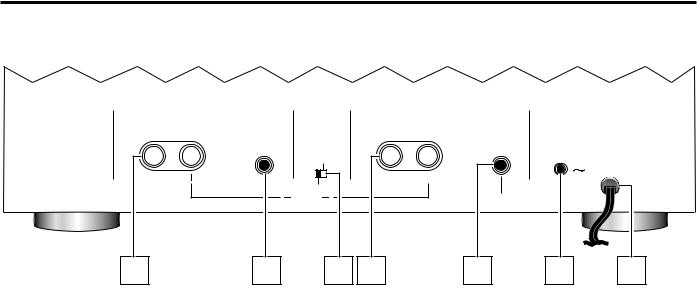
REAR PANEL CONNECTIONS
CHANNEL ONE (RIGHT) |
1 |
|
|
|
CHANNEL TWO (LEFT BRIDGE) |
2 |
|
||
SPEAKER |
|
|
|
SPEAKER |
|
||||
|
|
IN |
|
|
|
|
|
IN |
|
|
|
|
|
|
|
|
|
POWER AMP |
|
|
|
|
|
BRIDGE |
|
|
TRIGGER IN |
|
|
|
|
|
|
|
|
|
AC INPUT |
||
|
|
|
|
|
|
|
|
|
|
|
|
|
|
|
|
|
|
|
AC 120V/60Hz 600W |
4 |
MIN |
|
|
NORMAL |
|
4 |
MIN |
|
|
|
|
|
|
|
|
|
|
|
|
|
|
( |
) BRIDGE ( |
) |
|
|
BRIDGE IN |
|
|
|
|
|
8 |
MIN |
|
|
|
|
|
5 |
|
6 |
|
|
7 |
8 |
9 |
10 |
11 |
5 Channel One Output: When the amplifier is being used in the two-channel (Stereo) mode, connect the right channel speaker to the positive (+) and negative (-) terminals. When the amplifier is being used in the Bridged Mono mode connect the Positive (+) terminal ONLY to the Negative (-) terminal on your speaker.
6 Channel One Input: When the amplifier is being used in the two-channel (Stereo) mode, connect the right channel output of your preamp or processor to this input jack. When the amplifier is being used in the Bridged Mono mode, this jack is not used.
7 Bridge/ Normal Switch: When the amplifier is used for two-channel stereo operation, this switch should be in the NORMAL position. For Bridged Mono use only, place the switch in the BRIDGE position.
8 Channel Two Output: When the amplifier is being used in the two-channel (Stereo) mode, connect the left channel speaker to the positive (+) and negative (-) terminals.
When the amplifier is being used in the Bridged Mono mode connect the Positive (+) terminal ONLY to the Positive (+) terminal on your speaker.
Important Note: When the 1.5 is used in the Bridged Mono mode, do not connect a speaker with an impedance less than 8 ohms.
9 Channel Two/ Bridged Input: When the amplifier is being used in the two-channel (Stereo) mode, connect the left channel output of your preamp or processor to this input jack. When the amplifier is being used in the Bridged Mono mode, connect the output of your preamplifier or other line-level signal source to this jack.
10 Power Amp Trigger Input: Connect this jack to a matching 6- to 12-VDC trigger output on a compatible device to have the 1.5 automatically turn on from the Standby mode when voltage is applied from the triggering unit. Note that a 3.5mm mono mini-plug with a positive tip should be used for the connection.
11 AC Power Cord: Connect this plug to a non-switched AC outlet. Due to the high-current draw of the Signature 1.5, it is NOT recommended that the accessory outputs on the back of audio/video components be used to power this product.
3

Two Channel Amplifier |
Harman Kardon |
SIGNATURE 1.5 |
INSTALLATION
Note: When making any connections between source components, processors or preamplifiers and the 1.5, or when making any connections to speakers, be certain that both the input device and the 1.5 are turned off. To ensure that there will be no unwanted signal transients that can damage equipment or speakers, it is always best to unplug all equipment from AC power outlets before making any connections. Modern electronic products often have a “standby” mode that may be activated even though the product may appear to be turned off.
Power Control Connections
The Signature Series 1.5 amplifier features a built-in remote turn-on system that will automatically turn on the amplifier when another device in the system is switched on. To activate this system, this amplifier must be used in conjunction with compatible Signature Series or Harman Kardon products or other approved devices.
Note: Before making any connections to remote trigger outlets, it is critical that both the 1.5 and the triggering device be turned off. For additional safety, it is best that these connections be made while both products are unplugged from AC power sources.
Remote Turn-On with the Signature Series 2.0 and Compatible Harman Kardon Products
Connect one end of the accessory cable supplied with the
2.0 to the Power Amp Trigger In jack 10 on the rear of the 1.5. Connect the other end to the TRIGGER OUTPUT jack on the 2.0.
Remote Turn-On Using an External AC-to-DC Converter
If the 1.5 is not used with a compatible Harman Kardon product, it is still possible to activate the unit for automatic turn-on.
To control the amplifier in this manner you will need a small UL/CSA-approved class-2 AC-to-DC power converter capable of delivering a 6- to 12-volt DC signal. The DC voltage should terminate in a standard 3.5 mm mono miniplug, with the tip of the plug “positive” (+). This type of converter may be obtained as a “Power Adapter” from many electronics retailers. Consult your dealer for further information.
Plug the AC adapter into a switched outlet that will be activated when you wish to have the amplifier turn on. This may be the switched outlet at the rear of an AV receiver or other audio equipment, an AC outlet that is part of a current sensing control unit activated by a pre-amp or surround processor or a switched AC wall outlet.
Connect the 3.5 mm miniplug from the power converter to
the Power Amp Trigger In jack 10 on the rear of the 1.5.
Audio System Connections
As a general rule, avoid running any input signal or speaker wire connections next to or parallel with AC power cords. This may cause undesired hum or other interference that will greatly degrade signal performance.
When making input connections with RCA-type plugs on interconnect cables, make certain to gently but firmly insert the plugs into the jacks on the rear of the 1.5. Loose connections can cause intermittent sound and may damage your speakers.
Input Connections
Stereo Mode: For conventional two-channel stereo operation, connect the right channel output of your pre-amp or processor to the Channel One Input 6 and the left channel output to the Channel Two Input 9 . Make certain that the Bridge/ Normal Switch 7 is in the NORMAL position.
Bridged Mono Mode: To use the 1.5 as a single-channel, mono amplifier, connect the line-level output of your preamp, processor or other signal source to the Channel
Two/ Bridged Input connector 9 on the rear panel. No connection is required to the Channel One connector in this mode. Make certain that the Bridge/ Normal Switch 7 is in the BRIDGE position.
Output Connections
The final step of the installation process is to connect the amplifier to your speakers using high-quality cable. A pair of binding posts is provided for each channel output. These posts will accept bare wire or banana-type plugs. To ensure that the high-quality signals produced by the 1.5 are carried to your speakers without loss of clarity or resolution, we recommend that you use high-quality speaker cable. Many brands of cable are available, and the choice of cable may be influenced by the distance between your speakers and the amplifier, the type of speakers you use, personal preferences and other factors. Your dealer or installer is a valuable resource to consult in selecting a proper cable for connections between your amplifier and speakers.
Regardless of the brand or type of cable selected, we recommend that you use a cable constructed of high-strand-count copper with a gauge of 14 or smaller. When specifying cable, remember that the smaller the number, the thicker the cable.
4

Two Channel Amplifier |
Harman Kardon |
SIGNATURE 1.5 |
Cable with a gauge of 16 may be used for short runs of less than ten feet. We do not recommend the use of cables with an AWG equivalent of 18 or higher due to the power loss and degradation in performance that will occur.
Cables run inside walls should have the appropriate markings to indicate listing with UL (“CL-2/CL-3”), CSA (“FT-4”) or appropriate safety agency standards that may be required in your area. Questions about running cables inside walls should be referred to your installer or a licensed electrical contractor who is familiar with the NEC and/or the applicable building or electrical codes in your area.
Two-Channel/Stereo Systems: When installing a two-channel (stereo) system, connect the positive (+) and negative (-) terminals from the right and left speakers to the
matching terminals 5 8 on the rear panel of the 1.5. Make certain that the Bridge/Normal Switch 7 is in the N O R M A L p o s i t i o n . W h e n t h e 1 . 5 i s u s e d f o r two-channel/stereo operation, speakers with an impedance of no less than 4 ohms may be used.
Bridged Mono Applications: To use the 1.5 as a single-channel, mono amplifier, connect the (+) terminal on your speaker to the (+) terminal on the Channel Two
Output 8 on the 1.5. Connect the negative (-) terminal on your speaker to the positive (+) terminal on the Channel
One Output 5 .
Note: For mono applications, no connections are made to the negative (-) speaker output terminals on the 1.5. Make certain that the Bridge/Normal Switch 

position.
Important Note: When the 1.5 is used in the Bridged Mono mode, do not use speakers with an impedance of less than 8 ohms.
When making speaker connections, note that one conductor of the speaker cable may have no markings or an indication of (-) for negative polarity, and the other will have a red line, brand-name markings, a colored thread or some other positive-polarity indication (+).
The wire with the positive indication should be connected to the red terminals on both the 1.5 and your speakers. The negative wire should be connected to the black terminal on the 1.5 and the speakers.
If bare wire is used for connections, strip approximately 3/4”(20 mm) of insulation from the end of each wire and carefully twist the strands of each conductor together. Be careful not to cut the individual strands or twist them off; for optimal performance, all strands must be used.
Next, loosen the knobs of the speaker output terminals far enough so that the cap moves back on its threads past the
holes at the rear of the terminal. Making certain that you observe the correct polarity for the type of system being installed (Stereo or Bridged Mono), pass the exposed wire through the hole until the wire is visible from the bottom end. Holding the wire in place, twist the cap back so that the connection is secured. Do not overtighten or use tools, as this may damage the plastic terminal cap or break the delicate wire strands and decrease system performance.
Important Note: When making speaker wire connections, be certain that none of the strands from one lead touch any other lead. This will cause a short circuit and may damage your amplifier or speakers. Damage from short circuits caused in this manner is not covered by the product warranty.
Connections may also be made using spade lugs or standard 4 mm OD banana plugs. Before using a banana-type jack, make certain that the plastic screw caps on the 1.5 are firmly tightened by turning them clockwise until they are snug against the chassis. This will ensure that the maximum surface area of the plug is in contact with the jack. Once the wire has been attached to the banana plug following the plug manufacturer’s instructions, simply insert the banana plug into the hole provided on the rear of the colored screw caps on the terminal posts. Be certain to observe proper polarity.
Finally, run the cables to the speaker locations. It is highly recommended that the length of cable connecting any pair of speakers be identical. For example, make certain that the cable length connecting left and right front or left and right rear (surround) speakers is identical, even though one speaker may be physically closer to the amplifier than the other. Do not coil any excess cable, as this may become an inductor that creates frequency response variations in your system.
Connect the wires to the speakers, again being certain to observe proper polarity. Remember to connect the negative or black wire to the matching terminal on the speaker. Similarly, the positive or red wire should be connected to the like terminal on the speaker.
Note: While most speaker manufacturers adhere to an industry standard of using black terminals for negative and red ones for positive, some manufacturers may not adhere to this configuration. To ensure properly phased connections and optimal performance, consult the identification plate on your speaker terminals, or the speaker’s manual to verify polarity. If you do not know the polarity of your speaker, ask your dealer or installer for advice before proceeding, or consult the speaker’s manufacturer.
5

Two Channel Amplifier |
Harman Kardon |
SIGNATURE 1.5 |
OPERATION
The Signature 1.5 may be operated in either a manual or automatic mode. If the unit is being used in a stand-alone operation you should follow the instructions below for Manual Operation. When the Signature 1.5 is connected to another compatible device such as the Signature 2.0 or PT2500 tuner, follow the instructions for Automatic Operation.
Make sure the power switch is in the off position before plugging in the AC power cord. After all the connections have been made to the amplifier’s input jacks and speaker terminals, connect the power cord to an AC outlet. Turn on your source component and receiver/processor first; start with a low volume level to protect your speakers.
Manual Operation
The LED indicator should be glowing red if the unit is plugged in. Press the front panel switch to turn the unit on.
The indicator will flash green briefly, and then go out; the front panel will then illuminate to blue.
To turn the unit off, press the power switch again. The LED indicator will return to red.
Automatic Operation
Before proceeding, make certain the connection between the Signature 2.0, PT2500, or other trigger source has been connected properly to the unit following the previous directions. At this point the trigger source should be off.
After all cables are connected and the Signature 1.5 is plugged in, the LED Indicator should be glowing red. Press the power switch and the indicator will turn amber indicating the unit is in the standby mode and ready to turn on when it receives a signal from the triggering device. Finally, turn on your Signature 2.0, PT2500, or other trigger source to turn the Signature 1.5 on.
The indicator will flash green briefly, and then go out; the front panel will then illuminate to blue.
At the conclusion of your listening session, there is no need to turn the Signature 1.5 off manually. When the Signature 2.0, PT2500, or other trigger source is turned off, the Signature 1.5 will return to the standby mode.
Important Note: If you will not be using your audio system for an extended period of time, such as a vacation, we recommend turning the Signature 1.5 off using the power switch.
IDLE CURRENT ADJUSTMENT FOR SIGNATURE 1.5
Locate test points P4 and P5; these are 2 pin female molex connectors (2 total, 1 per channel) on the MAIN AMPLIFIER PCB near the speaker terminals.
Attach a DC voltmeter (set to a low range) to these points. This is best accomplished by making up a “test plug” using a male molex connector that fits into the one in the unit, with wires attached, for connection to the voltmeter. An alternate method is to use two “mini-grabbers” to attach to the two outer pins on each connection. Warning: Do not accidentally short the two points together with a meter probe during adjustment.
Adjustment Points: R60, R69
Adjust to 18mv across test points, one channel at a time, until both channels comply.
OUTPUT TRANSISTOR REPLACEMENT ON THE SIGNATURE 1.5
1)Remove the top cover.
2)Remove all molex connectors on the main amplifier board.
3)Remove the (4) outer screws holding the heatsink plate to the chassis.
4)Remove all outer Philips screws holding both speaker terminals and RCA connectors to the rear panel.
5)Angle and lift the entire amplifier assembly and heatsink up and out of the chassis.
6
 Loading...