


SUBTS-11
harman/kardon
SUB-TS11
(HKTS 11 SUBWOOFER
included in the HS300 system)
SERVICE MANUAL
harman/kardon, Inc.
250 Crossways Park Dr.
Woodbury, New York 11797 Rev1 3/2008

Note: The Sub-TS11 subwoofer is part of the HKTS 11 system,
included in the harman/kardon HS300 system
Satellite loudspeakers SAT-TS11 order hk part# HKTS 14-A SAT-E-P
Center channel CEN-TS11 order hk part# HKTS 7-A CEN-E -P
CONTENTS
BASIC SPECIFICATIONS . . . . . . . . . . . . ……………………………………. . . . 1
DETAILED SPECIFICATIONS. . . . . . . . . . . . . .. . . . . . . . . ………………….. …2
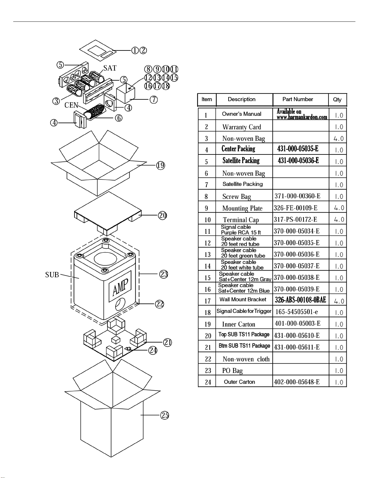
PACKAGING. . . . . . . . . . . . . .. . . . . . . ……………………… . . . . .. . .. .. .. . . . . 4
CONTROLS & CONNECTIONS . . . . . . . . . . . . . .. . . . . . . . . ………………….. 5
SPEAKER CONNECTIONS……………………….………..……. . . .. . .. . . . .. . .. 7
OPERATION……. . . . . .. . . . . . . . .. .. . . . .. .. . . . . ………………………………10
TEST PROCEDURE. . . . . . . . . . . ………………………………………………….11
UNIT EXPLODED VIEW. . . . …………… ……………. .. ………... . . .. .. ... . … . 12
AMPLIFIER EXPLODED VIEW. . . . ………………... . .. ………... . . .. . . .. . .… . 13
BLOCK DIAGRAM . . . . . . . . . . . . . .. . . . . . . ……………… . . . . .. . .. . .. . . . . 14
DETAILED TROUBLESHOOTING..…………………………………………………15
PCB DRAWINGS. .. . . . . . . . . . . . . . .. . . . . ……… . …………. . . . .. .. .. . .. . . . 16
ELECTRICAL PARTS LIST …………. .... . .. . . . …………………………... … . . 20
SEMICONDUCTOR PINOUTS . . . .. .. .. .. . . . .. . ……………..………..………. .25
SCHEMATIC DIAGRAMS . . . . . . . . .. .. .. .. . . . .. . ………………………..……. .26
SPECIFICATIONS
Amplifier Power (RMS) 200 Watts
Driver 10" (254mm) woofer, Bass Reflex Enclosure
Inputs Stereo Line Level, dedicated Subwoofer (LFE)
and Speaker Level with gold-plated binding posts
Outputs Speaker Level with gold-plated binding posts
Frequency Response 35Hz – 120Hz (Filter switch ON)
35Hz – 450Hz (Filter switch OFF)
External Trigger Input Voltage: 3-30 Volts AC/DC
Dimensions (H x W x D) 20-1/2" x 14-1/2" x 14-1/2" (521mm x 368mm x 368mm)
Weight 48 lb (21.8kg)
Occasional refinements may be made to existing products without notice but will always meet or exceed original specifications
unless otherwise stated.

HKTS 11 Sub 200W Powered Sub/ Plate Amp
LINE VOLTAGE Yes/N
o
Hi/Lo Lin
e
Nom. Uni
t
Note
s
US 120vac/60Hz Yes 108-132 120 Vrms
Normal Operatio
n
Parameter
Nonimal
Specification
Unit
QA Test
Limits
Conditions
Notes
Amp Sectio
n
Type (Class AB, D, other) D n/a
n/a
Bridge type amplifier, None of the
speaker terminals must be
connected to system GND at any
time.
Load Impedance (speaker) 3.5 Ohms
n/a
Nominal
Rated Output Power 200 Watts
150
50 - 250 Hz, 1 input driven, limiter off
THD @ Rated Power 0.08 %
0.1
22k filter
THD @ 1 Watt 0.15 %
0.5
22k filter
DC Offset 5 mV-DC
20
@ Speaker Outputs
Damping factor 16 n/a
10
Measured at amplifier board
Measured at the speaker at speak
e
output terminals on the amp board.
Input Sensitivit
y
Input Frequency 50 Hz
n/a
Nominal Freq.
Line (L&R) Input 220 mVrms
154 - 308
To Rated Power
Single input drive
n
SUB (LFE) Input 125 mVrms
87 - 175
To Rated Power
SUB (LFE) input driven onl
y
Speaker/Hi Level Input 3.4 Vrms
2.4 - 4.8
To Rated Power
(20 dB below Line In), Single input
driven
Hi Level Max. Input Voltag
e
32 Vrms
30
Nominal Freq., Min. Volume
Signal to Noise Rati
o
SNR-A-Weighted 85 dB
82
relative to rated power
A
-Weighting filte
r
SNR-unweighted 62 dB
59
relative to rated power
22k filte
r
SNR rel. 1W-unweighted 64 dB
59
relative to 1W Output
22k filte
r
Residual Noise Floor 1.2 mVrms
3.0
Volume @max, using RMS
reading DMM/VOM (or A/P)
Residual Noise Floor 0.8 mVrms
2.0
Volume @max, w/ A/P Swept
Bandpass Measurement (Line
freq.+ harmonics)
Input Impedanc
e
Line Input (L, R,LFE) 10K ohms
n/a
Nominal
Speaker/Hi Level Input 4.7K ohms
n/a
Nominal
Filter
s
L&R Fixed Low-Pass Filter 160 Hz
140 - 180
@ -6dB ref. 100Hz
3rd order fixe
d
SUB (LFE) Low pass Filter 270 Hz
240 - 300
@ -3dB ref. 100Hz
2nd order fixe
d
Subsonic filter (HPF) 3rd Order 25 Hz
22 - 28
@ -3dB ref. 30Hz
3rd order fixe
d
Limiter
THD at Max. Output Power
2.0 %
5.0
Features
Auto - On -Off Selection Switch YES
functional Refer to ATO sectio
n
Phase Switch 0-180 deg
functional
Filter On/Off Switch YES
functional
Volume Pot Taper (Lin/Log) LOG
functional
A
Tape
r
Speaker Out YES
functional Binding post connector L&
R
2-Color LED power indicator YES
functional Blue: On, Amber: Stand-b
y
Power Switch YES
functional
Fuse Holder YES
functional
Input Configuratio
n
Line In (L,R) YES
functional Dual RCA jack
SUB (LFE) YES
functional RCA jack
Speaker/Hi Level In YES
functional Binding post connector L&
R
Signal Sensing (ATO
)
Auto-Turn-On (yes/no) YES
functional
Auto - on selection switch in Auto
ATO Input test frequency 50 Hz
n/a
"
ATO Level Line & SUB Input 4.0 mV
2.0 - 6.0
"
ATO Level Speaker in 35 mV
20 - 50
"
ATO Turn-on time 0.9 sec.
functional
A
mp connected and AC on, then
input signal applied
2
SUB-TS11 (HKTS 11 Sub, HS300 system) harman/kardon
ATO Turn-OFF Time 12 minutes
5 - 17
Time before muting, after signal is
removed
Power on Delay tim
e
3 sec.
functional
AC Power Applied
Transients/Pop
s
ATO Transient 5 mV-peak
10
@ Speaker Outputs
Turn-on Transient 500 mV-peak
700
@ Speaker Outputs
A
C Line cycled from OFF to O
N
Turn-off Transient 500 mV-peak
700
@ Speaker Outputs
A
C Line cycled from ON to OF
F
Efficienc
y
Stand-by Input Power 8 Watts
12
@ nom. line voltage
Maximum allowable input power
under nominal input voltage and
frequency, in stand-by mode (HOT
or COLD operation).
Power Consumption @ rated power 240 Watts
250
@ nom. line voltage
200 Watts @ 3.5 ohms and
nominal line voltage
Protectio
n
Short Circuit Protection YES
functional
Direct short at output
A
mplifier should resume operation
after short circuit condition is
removed.
Thermal Protection YES
functional
Any user accessible metal parts
should always remain at 65 degree
C or less for domestic version or 5
5
degree C or less for EU version.
DC Offset Protection YES
functional
DC present at Speaker Out leads
Relay or crowbar (for driver/fir
e
protection),
Primary Fuse Rating
USA-Domestic 3.15 Amps
n/a
Type-T or Slo Blo (no DENTORI m
a
User-replacable fuse with
UL/SEMCO rated holder.
3
SUB-TS11 (HKTS 11 Sub, HS300 system) harman/kardon
SUB-TS11 (HKTS 11 Sub, HS300 system) harman/kardon
4
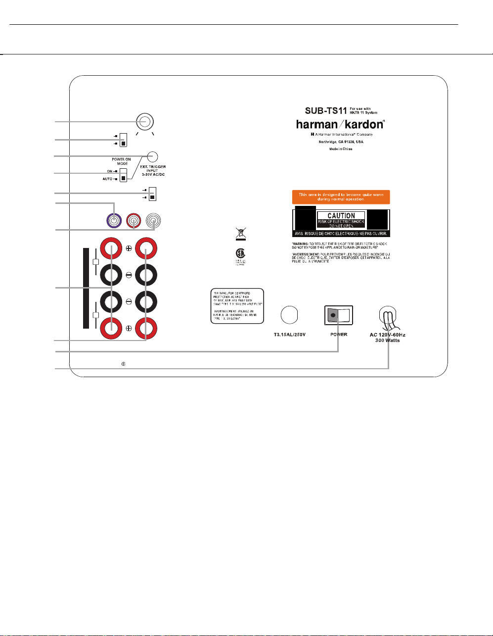
SUB-TS11 SUBWOOFER AMPLIFIER PANEL CONTROLS AND CONNECTIONS
OFF
ON
FILTER
NORMAL
REVERSE
PHASE
INOUT
R
L
LINE
LEVEL
IN
MAXMIN
IMPORTANT: CONNECT STRIPED WIRE
TO RED ( ) SPEAKER TERMINAL.
L
R
SUBWOOFER
LEVEL
H
I
G
H
L
E
V
E
L
™
£
¢
SUB
¡
§
ª
⁄
‚
¶
•
∞
¡ Subwoofer-Level Control: Volume
may be adjusted using the Subwoofer-
Level Control. Turn the control clockwise
to increase the SUB-TS11’s volume, or
counterclockwise to decrease it.
™ High-Cut (Low-Pass) Filter Switch:
Placing this switch in the ON position acti-
vates circuitry that cuts out all audio input
signals above 120Hz, allowing the SUB-TS11
to focus its power on reproducing the low-
frequency portion of the signal, avoiding inef-
ficiency and distortion. Engage this filter
when using the Speaker-Level Inputs ª,
or when using the Line-Level Full-Range
Inputs ¶, unless your receiver or processor
processes its line-level output using a low-
pass filter. The filter has no effect when the
SUB Input § is used.
£ External Trigger Input: Use the sup-
plied mini-plug cable to connect the trigger
output of another product to this jack. When
a trigger signal between 3 and 30 volts (AC
or DC) is detected, the SUB-TS11 amplifier
will turn on, even when the Audio-Sense
feature has been activated by placing the
Audio-Sense On/Off Switch ¢ in the
AUTO position. The amplifier will remain
on for about 10–15 minutes without an
audio signal.
¢ Audio-Sense On/Off Switch: When
placed in the AUTO position, and when the
Master Power Switch ‚ is turned on, the
SUB-TS11 will automatically turn itself on or
¡ Subwoofer-Level Control
™ High-Cut (Low-Pass) Filter Switch
£ External Trigger Input
¢ Audio-Sense On/Off Switch
∞ Phase Switch
§ Line-Level Subwoofer (SUB) Input
¶ Line-Level Full-Range Inputs
• Speaker-Level Outputs
ª Speaker-Level Inputs
‚ Master Power Switch
⁄ AC Power Cord
5
SUB-TS11 (HKTS 11 Sub, HS300 system) harman/kardon

SUB-TS11 SUBWOOFER AMPLIFIER PANEL CONTROLS AND CONNECTIONS
place itself in the Standby mode, depending on
whether it is receiving an audio signal. When
this switch is placed in the ON position, the
SUB-TS11 will remain on, whether or not it is
receiving an audio signal.
An LED located on top of the SUB-TS11
indicates whether the SUB-TS11 is in the On
or Standby state when used with the
Audio-
Sense On/Off Switch ¢ in the AUTO
position. The LED is lit blue to indicate that
the SUB-TS11 is receiving an audio signal
and is turned on, and the LED is lit amber to
indicate that no signal is being received and
the SUB-TS11 is in the Standby mode.
When the
Audio-Sense On/Off Switch ¢
is in the ON position, the LED will be lit
blue, whether or not an audio signal is
present.
When the
Master Power Switch ‚ is
turned off, the LED goes dark, no matter
which position the Audio-Sense On/Off
Switch ¢ is in.
∞ Phase Switch: This switch determines
whether the SUB-TS11 subwoofer’s piston-
like action moves in and out in phase with
the main speakers. If the speakers were to
play out of phase, the sound waves pro-
duced by the subwoofer would be canceled
out, reducing bass response.This phenome-
non depends in part on the relative place-
ment of the speakers in the room. In most
cases, the
Phase Switch ∞ should be left
in the NORMAL position. However, it
does no harm to experiment with the Phase
Switch ∞, and you may leave it in the
position that maximizes bass response.
§ Line-Level Subwoofer (SUB) Input:
Connect the subwoofer output of a receiver
with digital surround sound decoding, such
as Dolby
®
Digital or DTS
®
, to this input. This
input bypasses the SUB-TS11’s internal
crossover circuitry, and should only be used
with a filtered signal. If your receiver does not
have digital decoding, you should use the
Line-Level Full-Range Inputs ¶ instead.
¶ Line-Level Full-Range Inputs: Connect
the line-level subwoofer output or preamp out-
put(s) of your receiver or amplifier to these
inputs. If your receiver does not have a sepa-
rate subwoofer output, use a Y-adapter (not
supplied) to bridge the receiver’s preamp out-
put to the main amp input for that channel,
and connect the long end of the adapter
to the corresponding line-level input on the
SUB-TS11. If your receiver has only a single
subwoofer output, you may connect it to
either the left or right line-level input on the
SUB-TS11, and no Y-adapter is needed.
• Speaker-Level Outputs: If you are
using the Speaker-Level Inputs ª on the
SUB-TS11, you should connect these bind-
ing post terminals to your front left and right
speakers, remembering to maintain polarity
by connecting the (+) terminal on the
SUB-TS11 subwoofer to the (+) terminal
on the speaker, and the (–) terminal on the
SUB-TS11 subwoofer to the (–) terminal
on the speaker. If you are not using the
Speaker-Level Inputs ª, then connect
your front left and right speakers directly
to your receiver or amplifier. See pages 9
through 12 for further information on speaker
connections.
ª Speaker-Level Inputs: If your receiver
or amplifier does not have a line-level sub-
woofer output, connect these binding-post
terminals to the main left and right speaker
terminals of your receiver or amplifier.
Remember to maintain polarity by connecting
the (+) terminal on the receiver/amplifier to the
(+) terminal on the SUB-TS11 subwoofer, and
the (–) terminal on the receiver/amplifier to the
(–) terminal on the SUB-TS11 subwoofer.
‚ Master Power Switch: Place this
switch in the “•” position to power-on the
SUB-TS11 subwoofer. The SUB-TS11 will
then be either in the Standby mode or com-
pletely on, depending on the position of the
Audio-Sense On/Off Switch ¢.
⁄ AC Power Cord: Make sure to plug this
cord into an active, unswitched electrical out-
let for proper operation of the SUB-TS11.
The cord should not be plugged into the
accessory outlets found on some audio
components.
6
SUB-TS11 (HKTS 11 Sub, HS300 system) harman/kardon
Dolby
®
Digital or DTS
®
(or Other
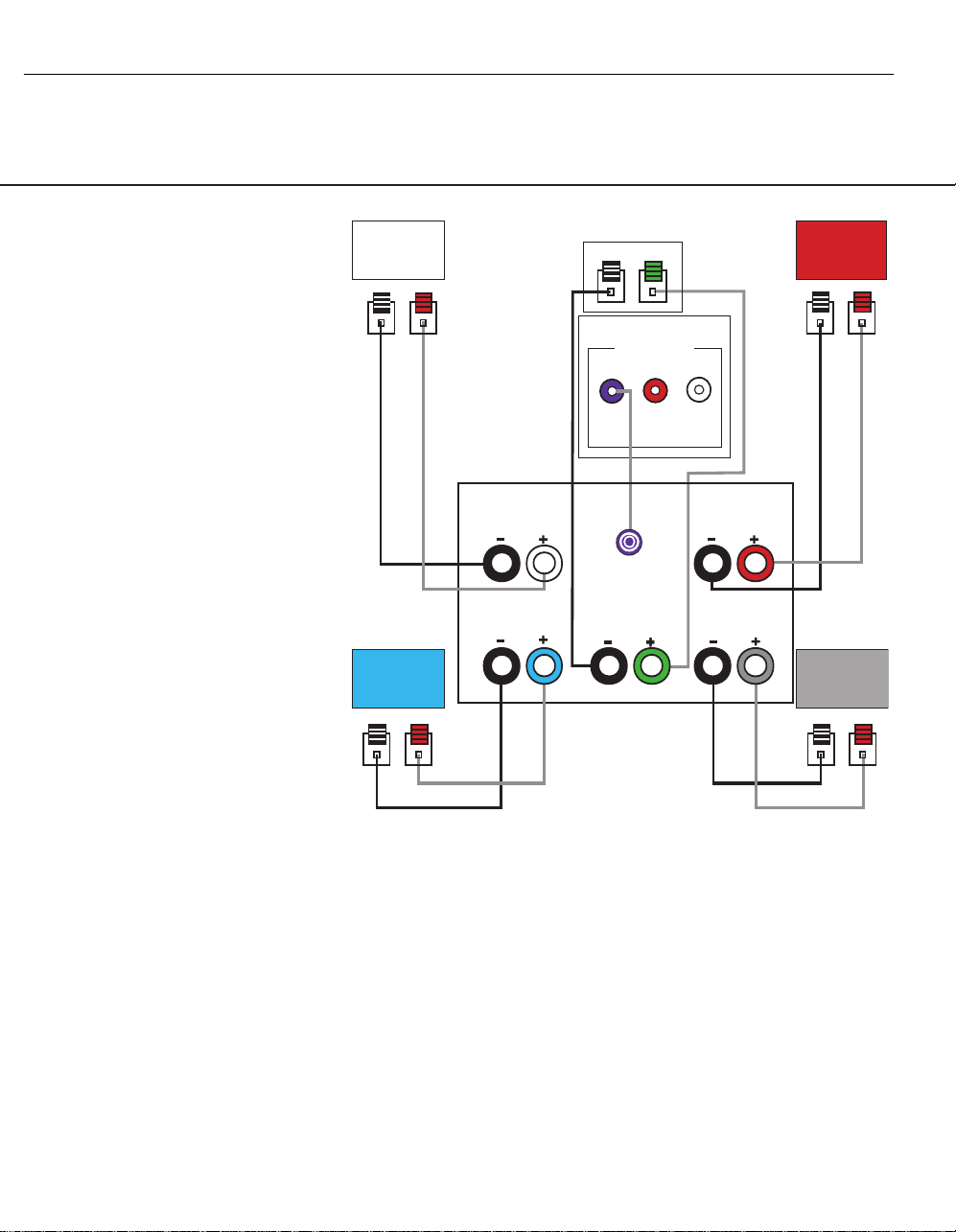
Digital Surround Mode) Connection
USE THIS INSTALLATION METHOD FOR
DOLBY DIGITAL, DTS OR OTHER DIGITAL
SURROUND PROCESSORS:
Use the line-level input jack marked
SUB
§ for the low-frequency effects channel.
Connect this jack to the subwoofer output
or LFE output on your receiver or amplifier.
Connect each speaker to the corresponding
speaker terminals on your receiver or
amplifier.
Make sure you’ve configured your surround
sound processor for “Subwoofer On.” The
front left, front right, center and surround
speakers should all be set to “Small.”
When all connections have been made, plug
the AC power cord on the subwoofer into
an AC outlet.
SPEAKER CONNECTIONS
LINE LEVEL IN
L
R
SUB
SUB/LFE
Out
SUB-TS11 Subwoofer
Receiver
Front
Left
Surround
Left
Front
Right
Surround
Right
Center
Surround
Right
Front
Right
Surround
Left
Front
Left
Center
– +
– +
– +
– +
– +
7
SUB-TS11 (HKTS 11 Sub, HS300 system) harman/kardon
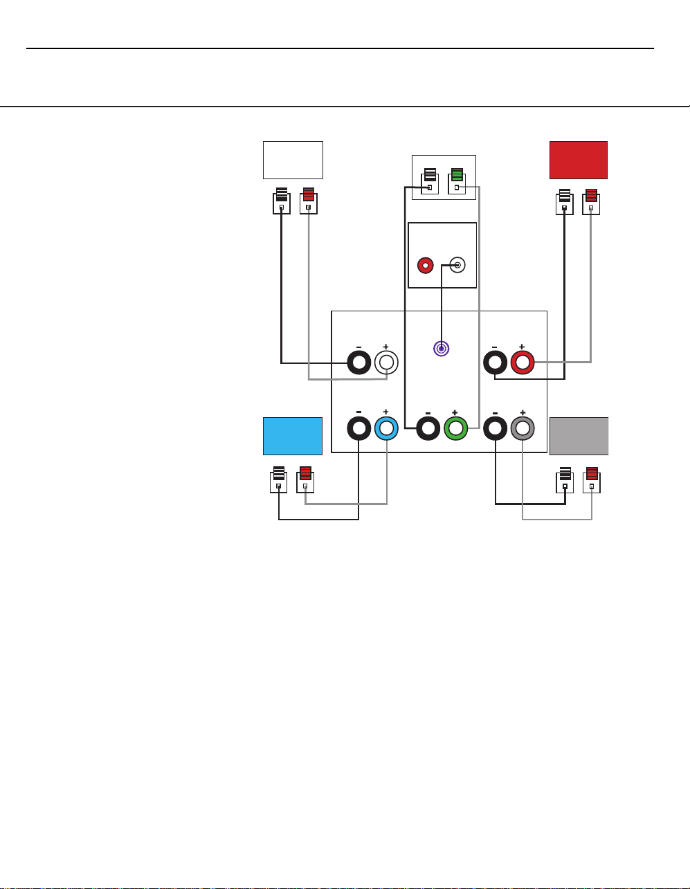
Dolby Pro Logic
®
(Non-Digital) – Line Level
USE THIS INSTALLATION METHOD FOR
DOLBY PRO LOGIC APPLICATIONS (NOT
DOLBY DIGITAL, DTS OR OTHER DIGITAL
PROCESSING), WHERE THE RECEIVER/
PROCESSOR IS EQUIPPED WITH A
SUBWOOFER OUTPUT, OR A VOLUME-
CONTROLLED PREAMP (LINE-) LEVEL
OUTPUT:
Use the supplied RCA-type interconnect
cable to connect the
line-level subwoofer
output on your receiver
or amplifier to either
the left or right Line-Level Full-Range
Input ¶ on the SUB-TS11 subwoofer.
Use both the left and right inputs on the
subwoofer if your receiver or processor has
both left and right line-level outputs. In that
case, you will need to supply a second
interconnect cable.
If your receiver is equipped with line-level out-
puts but does not have a separate subwoofer
output, use a Y-adapter (not supplied) to
bridge the receiver’s preamp output to the
main amp input for that channel, and connect
the long end of the adapter to the corre-
sponding line-level input on the SUB-TS11.
IMPORTANT: Do not use the SUB Input
§ on the subwoofer with Dolby Pro Logic
processors.
If your receiver/processor has a built-in low-
pass-crossover filter for the subwoofer out-
put, you may use the
SUB Input § to
bypass the subwoofer’s internal crossover.
Connect each speaker to the corresponding
speaker terminals on your receiver or amplifier.
Make sure that you have configured your
surround sound processor for “Subwoofer
On.” The front left, front right, center and
surround speakers should all be set to
“Small.”
When all connections have been made, plug
the AC power cord on the subwoofer into
an AC outlet.
SPEAKER CONNECTIONS
Receiver
SUB/LFE
Out
Front
Left
Surround
Left
Front
Right
Surround
Right
SUB-TS11
Subwoofer
Center
Line-Level
R
L
– +
– +
– +
– +
– +
Surround
Right
Front
Right
Surround
Left
Front
Left
Center
8
SUB-TS11 (HKTS 11 Sub, HS300 system) harman/kardon
 Loading...