

Page 1
Harman Kardon
Bass Treble Balance
Volume
P•SET P•SCN TUNE
VIDEO3
Video
RLMaxMinMaxMin
Audio
MUTECLR MODE
LR
TV DVD V1 V2 V3
TEST
PRO•LOGIC
3•STEREO MOVIE
HALL MATRIX
SLEEP
NIGHT
P-SCAN
LFE
ATT
DISP
MEMO
AUTO
TUNED
STEREO
dB
kHz
MHz
RF OPT COAX
AVR75
Audio/VideoReceiver
Owner’s Manual
Page 2

Owner’s Manual
AVR75 Audio/Video Receiver
Table of Contents
Introduction . . . . . . . . . . . . . . . . . . . . . . . . . . . . . . . . . . 1
Safety Information . . . . . . . . . . . . . . . . . . . . . . . . . . . 2–3
Unpacking and Installation . . . . . . . . . . . . . . . . 3
Front Panel Controls. . . . . . . . . . . . . . . . . . . . . . . . . . 4–5
Front Panel Information Display. . . . . . . . . . . . . . . . 6–7
Rear Panel Connections . . . . . . . . . . . . . . . . . . . . . . . 8–9
Remote Control Functions . . . . . . . . . . . . . . . . . . . 10–12
Installation and Setup . . . . . . . . . . . . . . . . . . . . . . 13–14
Remote Control Programming and Operation . . . 15–16
System Configuration . . . . . . . . . . . . . . . . . . . . . . . 17–20
Basic Operation. . . . . . . . . . . . . . . . . . . . . . . . . . . . 21–24
Source Selection . . . . . . . . . . . . . . . . . . . . . . . . 21
Surround Mode Selection . . . . . . . . . . . . . . . . . 21
Digital Audio Sources . . . . . . . . . . . . . . . . . . . . 22
Tuner Operation . . . . . . . . . . . . . . . . . . . . . 22–24
On-Screen Display. . . . . . . . . . . . . . . . . . . . . . . . . . 25–27
Advanced Features. . . . . . . . . . . . . . . . . . . . . . . . . . 28–31
Audio Tape Dubbing . . . . . . . . . . . . . . . . . . . . . 28
Delay Time Adjust. . . . . . . . . . . . . . . . . . . . 28–29
Digital Audio Playback. . . . . . . . . . . . . . . . 29–30
Surround Mode Chart . . . . . . . . . . . . . . . . . . . . 31
Troubleshooting Guide . . . . . . . . . . . . . . . . . . . . . . . . . 32
Technical Specifications . . . . . . . . . . . . . . . . . . . . . . . . 33
80 Crossways Park West
Woodbury, NY 11797
www.harmankardon.com
©1997 Harman Kardon, Incorporated
Page 3

Introduction
1
Congratulations! With the purchase
of a Harman Kardon AVR75 you are
about to begin many years of listening
enjoyment. The AVR75 has been custom
designed to provide all the excitement
and detail of movie soundtracks and
every subtle nuance of musical selections. With on board Dolby*Digital
Decoding, the AVR75 delivers six discrete
channels of audio that take advantage of
the digital soundtracks from the latest
DVD and LV releases.
While complex digital systems are hard
at work within the AVR75 to make all of
this happen, hook-up and operation are
simple. Color-keyed connections, a comprehensive remote control and on-screen
menus make the AVR75 easy to use. To
obtain the maximum enjoyment from
your new receiver we urge you to take a
few minutes to read through this manual.
This will ensure that connections to
speakers, source playback units and other
external devices are made properly. In
addition, a few minutes spent learning
the functions of the various controls will
enable you to take advantage of all the
power the AVR75 is able to deliver.
Description and Features
The AVR75 is a full-featured A/V receiver,
incorporating a wide variety of listening
options. In addition to Dolby Digital
decoding, Dolby Pro Logic*and Dolby 3
Stereo are available for compatibility with
the tens of thousands of movies and tele-
vision programs encoded with analog
surround information. A choice of Hall,
Matrix and Movie modes is also available
for use with both encoded sources and
traditional two-channel stereo recordings.
A total of five audio/video inputs, each
with both composite and S-Video, as
well as three additional audio only
inputs are selected through a learning
remote control and an easy to read front
panel display or on-screen graphics
through a TV monitor.
The AVR75’s powerful amplifier uses
traditional Harman Kardon High Current
design philosophies to meet the wide
dynamic range of any program selection.
Harman Kardon invented the highfidelity receiver over forty years ago.
With state-of-the-art circuitry and timehonored circuit designs, the AVR75 is
undoubtedly the finest receiver ever
offered by Harman Kardon.
■ On-Board Dolby Digital Decoding
■ Coax, Optical or RF Digital Inputs
■ On-Screen Menu Displays
■ Learning Remote Control
■ Composite and S-Video Switching
■ Preamp Output for ALL Channels
Permits Ease of Expansion
If you have any questions about this
product, its installation or operation,
please contact your retailer or custom
installer. They are your best local source
of information.
Page 4
Safety Information
CAUTION:
TO REDUCE THE RISK OF ELECTRIC SHOCK, DO NOT REMOVE
COVER (OR BACK). NO USER-SERVICEABLE PARTS INSIDE. REFER
SERVICING TO QUALIFIED SERVICE PERSONNEL.
WARNING:
TO REDUCE THE RISK OF FIRE OR ELECTRIC SHOCK,
DO NOT EXPOSE THIS APPLIANCE TO RAIN OR MOISTURE.
CAUTION:
TO PREVENT ELECTRIC SHOCK, MATCH WIDE
BLADE OF PLUG TO WIDE SLOT, FULLY INSERT.
ATTENTION:
POUR EVITER LES CHOCS ELECTRIQUES, INRODUIRE LA
LAME LA PLUS LARGE DE LA FICHE DANS LA BORNE CORRESPONDANTE DE
LA PRISE ET POUSSER JUSQU'AU FOND.
The lightning flash with arrowhead
symbol, within an equilateral triangle, is
intended to alert the user to the
presence of uninsulated “dangerous voltage”
within the product’s enclosure that may be of
sufficient magnitude to consittute a risk of
electric shock to persons.
The exclamation point within an
equilateral triangle is intended to
alert the user to the presence of
important operating and maintenance
(servicing) instructions in the literature
accompanying the appliance.
CAUTION
RISK OF ELECTRIC SHOCK
DO NOT OPEN
2
Important Safety Information
CATV or Antenna Grounding
If an outside antenna or cable system is
Verify Line Voltage Before Use
Your AVR75 hasbeen designed for use
with 120-volt AC current. Connection to a
line voltage other than that for which it
is intended can create a safety and fire
hazard, and may damage the unit.
connected to this product, be certain that
it is grounded so as to provide some protection against voltage surges and static
charges. Section 810 of the National
Electrical Code, ANSI/NFPA No. 70-1984,
provides information with respect to
proper grounding of the mast and supIf you have any questions about the voltage requirements for your specific model,
or about the line voltage in your area,
contact your selling dealer before plugging the unit into a wall outlet.
porting structure, grounding of the lead-
in wire to an antenna discharge unit,
size of grounding conductors, location of
antenna discharge unit, connection to
grounding electrodes and requirements
of the grounding electrode.
Do Not Use Extension Cords
To avoid safety hazards, use only the
power cord attached to your unit. We do
not recommend that extension cords be
used with this product. As with all electrical devices, do not run power cords under
rugs or carpets or place heavy objects on
them. Damaged power cords should be
replaced immediately with cords meeting
factory specifications.
NOTE TO CATV SYSTEM INSTALLER:
This reminder is provided to call the
CATV (Cable TV)system installer’s atten-
tion to article 820-40 of the NEC that
provides guidelines for proper grounding
and, in particular, specifies that the cable
ground shall be connected to the ground-
ing system of the building, as close to the
point of cable entry as possible.
Handle the AC Power Cord Gently
When disconnecting the power cord from
an AC outlet, always pull the plug, never
pull the cord. If you do not intend to use
the unit for any considerable length of
time, disconnect the plug from the AC
outlet.
Do Not Open The Cabinet
There are no user-serviceable components inside this product. Opening the
cabinet may present a shock hazard, and
any modification to the product will void
your guarantee. If water or any metal
object such as a paper clip, wire or a
staple accidentally falls inside the unit,
disconnect it from the AC power source
immediately, and consult an authorized
service station.
Installation Location
■ To assure proper operation, and to
avoid the potential for safety hazards,
place the unit on a firm and level surface. When placing the unit on a shelf,
be certain that the shelf and any
mounting hardware can support the
weight of the product.
■ Make certain that proper space is pro-
vided both above and below the unit
for ventilation. If this product will be
installed in a cabinet or other enclosed
area, make certain that there is sufficient air movement within the cabinet.
Under some circumstances a fan may
be required.
■ Do not place the unit directly on a
carpeted surface.
■ Avoid installation in extremely hot or
cold locations, or an area that is
exposed to direct sunlight or heating
equipment.
■ Avoid moist or humid locations.
■ Do not obstruct the ventilation slots on
the top of the unit, or place objects
directly over them.
Page 5

Safety Information
3
Cleaning
When the unit gets dirty, wipe it with a
clean, soft dry cloth. If necessary, wipe it
with a soft cloth dampened with mild
soapy water, then a fresh cloth with clean
water. Wipe dry immediately with a dry
cloth. NEVER use benzene, aerosol
cleaners, thinner, alcohol or any other
volatile cleaning agent. Do not use
abrasive cleaners, as they may damage
the finish of metal parts. Avoid spraying
insecticide near the unit.
Moving The Unit
Before moving the unit, be certain to disconnect any interconnection cords with
other components, and make certain
that you disconnect the unit from the AC
outlet.
Important information for the user
NOTE: This equipment has been tested
and found to comply with the limits for
a Class B digital device, pursuant to Part
15 of the FCC Rules. The limits are
designed to provide reasonable protection
against harmful interference in a
residential installation. This equipment
generates, uses and can radiate radio
frequency energy and, if not installed and
used in accordance with the instructions,
may cause harmful interference to radio
communication. However, there is no
guarantee that harmful interference will
not occur in a particular installation.
If this equipment does cause harmful
interference to radio or television reception, which can be determined by turning
the equipment off and on, the user
is encouraged to try to correct the interference by one or more of the following
measures:
■ Reorient or relocate the receiving
antenna.
■ Increase the separation between the
equipment and receiver.
■ Connect the equipment into an outlet
on a circuit different from that to
which the receiver is connected.
■ Consult the dealer or an experienced
radio/TV technician for help.
This device complies with Part 15 of the
FCC Rules. Operation is subject to the
following two conditions: (1) this device
may not cause harmful interference, and
(2) this device must accept interference
received, including interference that may
cause undesired operation.
NOTE: Changes or modifications may
cause this unit to fail to comply with
Part 15 of the FCC Rules and may void
the user’s authority to operate the
equipment.
Unpacking and Installation
The carton and shipping materials used
to protect your new receiver during ship-
ment were specially designed to cushion
it from shock and vibration. We suggest
that you save the carton and packing
materials for use in shipping if you move
or should the unit ever need repair.
To minimize the size of the carton in
storage, you may wish to flatten it. This
is done by carefully slitting the tape
seams on the bottom and collapsing the
carton down to a more two-dimensional
appearance. Other cardboard inserts may
be stored in the same manner. Packing
materials that cannot be collapsed
should be saved along with the carton in
a plastic bag.
If you do not wish to save the packaging
materials, please note that the carton
and other sections of the shipping protection are recyclable. Please respect the
environment and discard those materials
at a local recycling center.
Typographic Conventions
In order to help you use this manual
with the remote control, front panel
controls, rear panel connections and
on-screen menus, certain conventions
have been used.
EXAMPLE – (bold type) indicates a
specific remote control or front panel
button, or rear panel connection jack
EXAMPLE – (OCR type) indicates a
message that is visible through the onscreen menu system
1 – (number in a square) indicates a
specific front panel control
a – (number in an oval) indicates a
button or indicator on the remote
¡ – (number in a circle) indicates a
rear panel connection
A – (letter in a square) indicates an
indicator in the front panel display
Page 6
Front Panel Controls
AM•FM T•MONCD T•2 TV DVD V1 V2 V3 OSD ATT MEMO
Bass
Phones NightPower CoaxOPTRF
Digital Input
Treble Balance
Volume
P•SET P•SCN TUNE
VIDEO3
Video
RLMaxMinMaxMin
Audio
MUTECLR MODE
AVR 75
VISUAL
TV DVD V1 V2 V3
TEST
DIGITAL
STEREO
AC-3 PCM
PRO•LOGIC 3•STEREO MOVIE
HALL MATRIX
SLEEP
NIGHT
P-SCAN
LFE
ATT
DISP
MEMO
AUTO
TUNED
STEREO
dB
kHz
MHz
RF OPT COAX
Mode
LR
1
2
3
ıˆ
Û
Ú4
57
9
)@
#$%^&
*
(ÓÔÒ
!
68
Ù
4
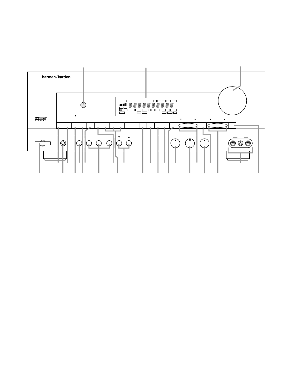
1 Power
2 AM/FM Tuner Mode Selector
3 Headphone Jack
4 CD
5 Tape1/Monitor
6 Night Mode
7 Tape 2
8 TV Input
9 Digital Input Selectors
) DVD Input
! Video Sources
@ Mode
# OSD (On-Screen Display)
$ ATT (Attenuation) Mode Select
% Memo
^ Clear
& FM Mode
* Bass
( Treble
Ó P-Set
Ô Balance
P-Scan
Ò Tune
Ú Video 3 Input
Û Mute
Ù Volume Control
ı Information Display
ˆ Remote Sensor Window
Page 7

Front Panel Controls
5
1 Power: Press this button once to
turn the unit on and off. Once the
unit is turned on, it may be turned off
and then on again from the remote, if
desired.
NOTE: When the remote is used to
turn the unit off the LED surrounding
the Power Switch will turn amber,
indicating that the AVR75 is in a
Standby mode. In this condition the
unit is NOT disconnected from the
AC main power supply.
2 AM/FM T uner Selector: Press
this button once to select the tuner.
Press it again to switch between AM
and FM.
3 Headphone Jack: Plug standard
stereo headphones into this jack for
private listening.
NOTE: When the headphones are in
use the output to the speakers is
muted and the surround mode is
automatically switched to STEREO.
When the headphones are removed
from the jack, sound to the speakers
is restored and the unit returns to the
previous sound mode.
4 CD: Press this button to select
the CD player.
5 Tape1/Monitor: Press this button
to select Tape One as the input
source. A red LED above the button
will illuminate to indicate that the
Tape Monitor has been selected.
6 Night Mode: Press this button to
activate the “Night” mode, preventing loud playback when the digital
modes are in use.
7 Tape2: Press this button to select
Tape 2 input.
8 TV Input: Press this button to
select the source connected to the
TV Input ª.
9 Digital Input Selectors: Press
one of these buttons to select a
digital input source. The digital
audio source may be the same as,
or different from, the analog audio of
the selected video source.
) DVD Input: Press this button to
select the source connected to the
DVD Input •. Note that if the DVD
or LV player’s digital audio output is
used, it must be selected separately
using the Digital Input Selectors
9g.
! Video Sources: Press any of
these buttons to select a video input
source.
@ Mode: Press these buttons to
scroll up ⁄ or down ¤ through the
list of available surround modes.
# OSD (On-Screen Display):
Press the button briefly to display a
system status report on your video
screen.
$ ATT (Attenuation) Mode Select:
Press this button to activate the
Attenuation mode which cuts the
analog input signal by 50% to com-
pensate for high-level input sources.
% Memo: The memo button is used
to enter stations to the tuner’s preset
memory in either the manual or
automatic modes.
^ Clear: The clear button is used
to cancel tuning, memory input or
when clearing the unit’s memories.
& FM Mode: Press this button
to select the tuning mode for FM
stations.
* Bass: This knob adjusts the tone
of low-frequency sounds. Turn it to
the right to boost bass frequencies
or to the left to cut bass frequencies.
( Treble: This knob adjusts
the tone of high-frequency sounds.
Turn to it the right to boost high
frequencies or to the left to cut high
frequencies.
Ó P-Set: Press this button to manu-
ally scroll up ⁄ or down ¤ through
the FM or AM stations programmed
into the receiver’s preset memory.
Ô Balance: This knob adjusts the
balance between the front left and
right speakers.
P-Scan: Press this button to
automatically scan through the
FM or AM stations preset into the
receiver’s memory. Press the button
again to stop the scan when the
tuner is at the desired station.
Ò Tune: Press this button to manu-
ally scan up ⁄ or down ¤ through
the FM or AM bands.
Ú Video 3 Input: Audio or Video
sources connected to these jacks
may be selected by pressing the
Video Source button !.
Û Mute: Press this button to cut
the output to the speakers. Press
it again to return to the previous
volume level.
Ù Volume Control: Turn the knob
clockwise to increase volume,
counterclockwise to decrease the
volume. Note that approximately two
revolutions of the knob are required
to go from no output to maximum
volume.
ı Information display: This
display delivers messages and
status indications to help you operate
the receiver. Refer to the separate
diagram for complete explanation of
the FL display.
ˆ Remote Sensor Window: The
sensor behind this window receives
infrared signals from the remote control. Aim the remote at this area and
do not block or cover it unless an
external remote sensor is installed.
Page 8
Front Panel Information Display
VISUAL
TV DVD V1 V2 V3
TEST
DIGITAL
STEREO
AC-3 PCM
PRO•LOGIC
3•STEREO MOVIE
HALL MATRIX
SLEEP
NIGHT
P-SCAN
LFE
ATT
DISP
MEMO
AUTO
TUNED
STEREO
dB
kHz
MHz
RF OPT COAX
A
QPRONMLK
BCFGH
I
J
DE
6
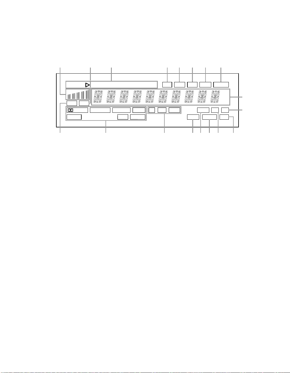
A AC-3 Indicator
B Surround Mode Status
C Digital Mode Indicators
D Sleep Indicator
E Night Indicator
F P-Scan
G LFE Indicator
H DISP
I ATT Indicator
J Main Information Display
K Stereo
L Tuned
M Auto
N Memo
O Test
P “Visual” Indicator
Q PCM Indicator
R Signal Level Indication
Page 9

Front Panel Information Display
7
A AC-3 Indicator: This indicator
illuminates when the AVR75 is
decoding a Dolby Digital input
source.
B Surround Mode Status: These
indicators display the currently
selected surround mode.
C Digital Mode Indicators: These
indicators show which digital input is
in use.
D Sleep Indicator: This indicator
lights when the AVR75 is in the
Sleep mode.
E Night Indicator: This indicator
lights when the AVR75 is in the Night
mode, which prevents the AVR75
from loud playback when digital
sources are in use.
F P-Scan: This indicator flashes
when the stations programmed
into the tuner memory are being
automatically reviewed.
G LFE Indicator: This indicator will
illuminate when the Low-Frequency
Effects (LFE) option has been turned
on through the controls in SETUP
MENU 3.
H DISP: This indicator lights when
the FL display has been turned
off using the Display button p to
remind you that the unit is still
turned on.
I ATT Indicator: This indicator
lights when the Attenuation function
has been engaged to cut the input
from analog sources by approxi-
mately 50%.
J Main Information Display: This
ten-digit display shows messages
relating to the status, input source,
surround mode, tuner, volume level
or other aspects of unit’s operation.
K Stereo: This indicator lights when
an FM station is broadcasting in
stereo.
L Tuned: This indicator lights when
an AM or FM station is properly
tuned and locked.
M Auto: This indicator signifies that
the Automatic Tuning mode is in use
for FM broadcasts.
N Memo: This indicator flashes
when the Memo button is pressed
when entering presets and other
information into the tuner’s memory.
O Test: This indicator flashes when
the output levels are being set using
the built-in test signal generator.
P “Visual” Indicator: These indica-
tors display which input source is
being fed to the video monitor output.
Q PCM Indicator: This indicator
illuminates to show that a standard
PCM (S/P-DIF) digital audio signal
is being decoded by the digital-toanalog converter.
R Signal Level Indication: This is a
visual indication of the strength of a
radio station signal. The more bars
visible, the stronger the station.
Page 10
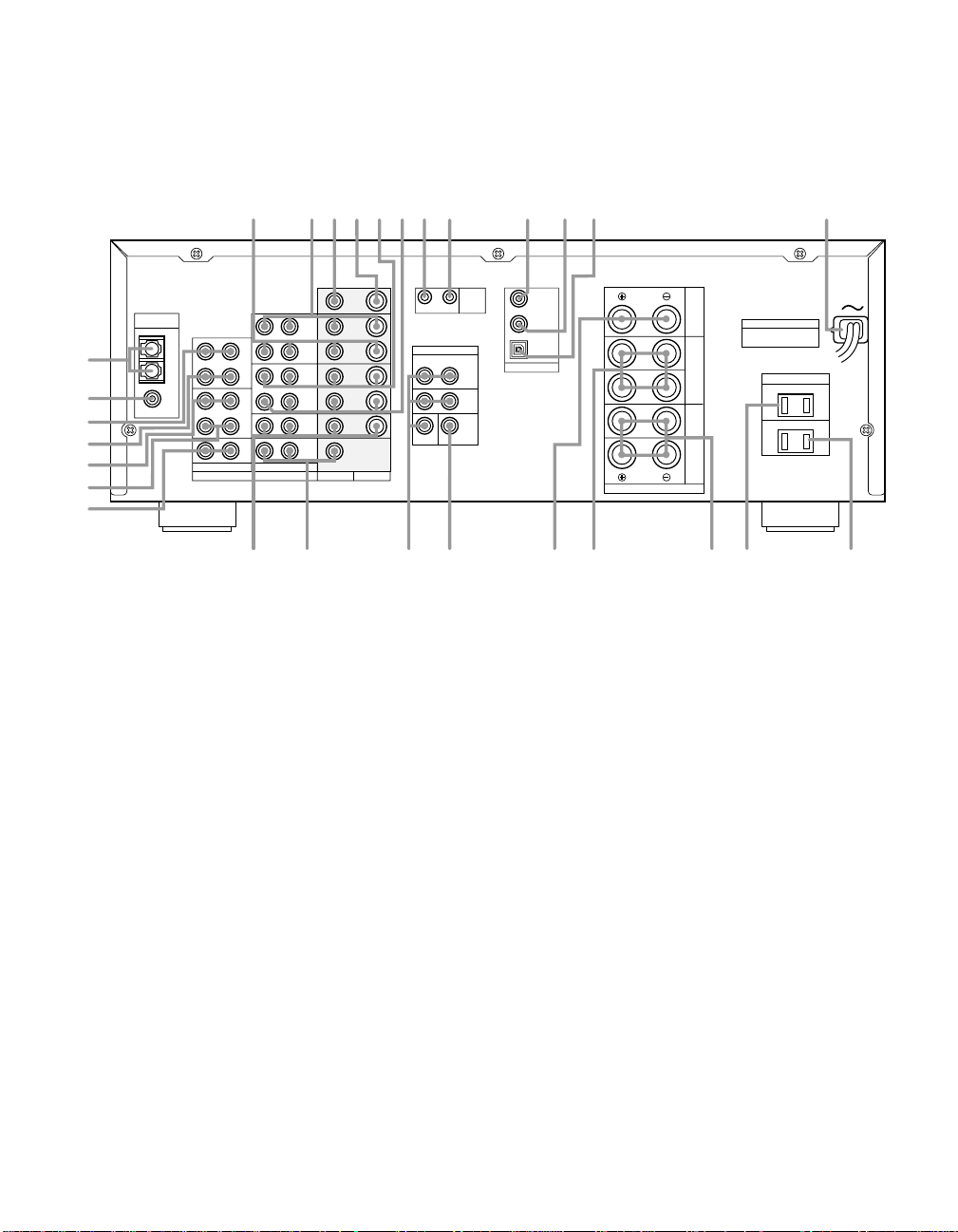
Rear Panel Connections
SWITCHED 120W 1.0A
AC OUTLETS (120V 60Hz)
SURR.
8 OHMS
CENTER
8 OHMS
FRONT
8 OHMS
PRE OUT
OUT
REMOTE
CONT.
AC-3/PCM
OPTICAL
AC-3/PCM
COAXIAL
AC-3
RF IN
IN
L R
SUB
WOOFER
SURR.
FRONT
L
R
SPEAKERS
UNSWITCHED 120W 1.0A
OUT
TAPE2
IN
DVD
TV
OUT
TAPE1
IN
CD
OUT
VIDEO2
IN
OUT
VIDEO1
IN
LR LR
AUDIO VIDEO
S-VIDEO
FM
(75Ω)
AM
ANTENNA
GND
TV
MONI
OUT
VIDEO2
IN
OUT
VIDEO1
IN
DVD
TV
CENTER
DIGITAL INPUT
L
R
MODEL NO.: AVR75
HARMAN KARDON
NORTHRIDGE
CALIFORNIA, U.S.A.
MADE IN JAPAN
SERIAL NO.
AC 120V
60 Hz
4.5 A
£
¢
§
¶
∞
™
¡
AUDIO
•ª ‚⁄ ‹¤›fifl
ba·°edcfgi‡
OUT
VIDEO2
IN
OUT
VIDEO1
IN
VIDEO2
VIDEO1
h
8
¡ AM Antenna
™ FMAntenna
£ Tape 2 Out
¢ Tape 2 In
∞ Tape 1 Out
§ Tape 1 In
¶ CD IN
• DVD Inputs
ª TV Inputs
‚ Pre-Outs
⁄ Subwoofer Pre-Out
¤ Center
‹ Surround
› Front
fi Switched AC Outlet
fl Unswitched AC Outlet
‡ Power Cable
° AC-3/PCM Optical Input
b Remote IR In
c Remote IR Out
d VCR1 Inputs
e VCR1 Outputs
f TV Monitor S-Video Output
g TV Monitor Video Output
h VCR2 Outputs
i VCR2 Inputs
· AC-3/PCM Coaxial Input
a AC-3 RF Input
Page 11

Rear Panel Connections
9
¡ AM Antenna: Connect the AM
loop antenna supplied with the
receiver to these terminals. If an
external AM antenna is used, make
connections to the AM and GND
terminals in accordance with the
instructions supplied with the
antenna.
™ FM Antenna: Connect an indoor
or external FM antenna to this
terminal.
£ Tape 2 Out: Connect these jacks
to the RECORD/INPUT jacks of a
second audio recorder.
¢ Tape 2 In: Connect these jacks to
the PLAY/OUT jacks of a second
audio recorder.
∞ Tape 1 Out: Connect these jacks
to the RECORD/INPUT jacks of an
audio recorder.
§ Tape 1 In: Connect these jacks to
the PLAY/OUT jacks of an audio
recorder.
¶ CD IN: Connect these jacks to
the output of a compact disc player
or CD changer.
• DVD Inputs: Connect the analog
audio outputs and composite or
S-Video output of a DVD or LV player
to these jacks.
ª TV Inputs: Connect these jacks
to the audio and video outputs of a
TV Tuner, Cable TV converter box,
satellite receiver, or any other
audio/video source.
‚ Pre-Outs: If external power
amplifiers are used for any channels,
connect them to these jacks.
⁄ Subwoofer Pre-Out: Connect
this jack to the line level input of a
powered subwoofer. If an external
subwoofer amplifier is used, connect
this jack to the subwoofer amplifier
input.
¤ Center: Connect these terminals
to the center speaker.
‹ Surround: Connect these
terminals to the surround speakers.
› Front: Connect these terminals to
the front speakers.
fi Switched AC Outlet: This outlet
may be used to power any device
that you wish to have on when the
unit is turned on.
fl Unswitched AC Outlet: This
outlet may be used to power any AC
device. The power will remain on at
this outlet regardless of whether the
AVR75 is on or off.
NOTE: The power consumption of
the device plugged into each of
these outlets should not exceed 120
watts.
‡ Power Cable: Connect the AC
plug to a non-switched AC wall
output.
° AC-3/PCM Optical Input:
Connect the optical digital output
from a DVD player, HDTV receiver,
LV player or CD player to this jack.
The signal may be either a Dolby
Digital (AC-3*) signal or a standard
PCM digital source.
· AC-3/PCM Coaxial Input:
Connect the coax digital output from
a DVD player, HDTV receiver, LV
player or CD player to this jack. The
signal may be either a Dolby Digital
(AC-3) signal or a standard PCM
digital source.
a AC-3 RF Input: Connect the
AC-3 RF output of an LV player
equipped for digital audio to this
jack.
NOTE: Do not connect standard
analog audio sources to these jacks
°·a.
b Remote IR In: If the AVR75’s front
panel IR sensor is blocked due to
cabinet doors or other obstructions,
an external IR sensor may be used.
Connect the output of the sensor to
this jack.
c Remote IR Out: This connection
permits the IR sensor in the receiver
to serve other remote controlled
devices. Connect this jack to the “IR
IN” jack on Harman Kardon or other
compatible equipment.
d VCR 1 Inputs: Connect these
jacks to the audio, video and
S-Video PLAY/OUT jacks of a VCR.
e VCR 1 Outputs: Connect these
jacks to the audio, video and
S-Video RECORD/IN jacks of a VCR.
f TV Monitor S-Video Output:
Connect this jack to the S-Video
input of a TV monitor or video
projector to view S-Video sources
selected by the receiver’s video
switcher.
NOTE: Standard (composite) video
and S-Video signals will appear only
at their respective output. The AVR75
does not convert one video format
to another.
g TV Monitor Video Output:
Connect this jack to the standard
(composite) video input of a TV
monitor or video projector to view
the on-screen menus and the
output of any standard video source
selected by the receiver’s video
switcher.
h VCR 2 Outputs: Connect these
jacks to the audio, video and
S-Video RECORD/IN jacks of a
second VCR.
i VCR 2 Inputs: Connect these
jacks to the audio, video and
S-Video PLAY/OUT jacks of a
second VCR.
Page 12

*
PRESET
DISC
ON OFF
DISPLAY
/
MUTE
Source Power
DVD
TV
VID 1
VID 2
TAPE 2
SELECT
TAPE 1
CD
AM/FM
VID 3
#
SKIP
TUNE/
SEARCH
VOLUME
+
_
SLEEP
MOVIEAC-3
NIGHT 123
STEREO MATRIX HALL
DELAY
4
5
6
RF
789
TEST TONE
SPEAKER
CH SELECT
COAX
OPT
0
OSD
AVR 75
Sending
Use
Learning
Learn
P/L 3 ST
ON OFF
Main Power
PTY
DEF GHI
JKL
MNO PQR
STU VWX YZ
MEMO
CLEAR P-SCAN
ABC
AF
FM MODE
RDS DISP.
TUNE/
SEARCH
OSD
b
c
d
e
f
g
h
i
j
k
l
m
a
n
o
p
q
r
s
t
u
v
w
x
y
z
`
MEMO
CLEAR P-SCAN
Remote Control Functions
10
a Use/Learn
b Source Power
c Main Power
d Source Selection
e Night Mode
f Delay
g Digital Audio Input Selectors
h AM/FM
i Menu Controls
j Select
k OSD
l Test Tone
m Channel Select
n Speaker Level Adjust
o Main Volume
p Display
q Mute
r Transport Controls
s Tune/Search and Fast Forward
t Preset/Disc
u Channel/Skip
v Memo
w P-Scan
x Number Keys
y Surround Mode Selection
z Sleep
` Learn LED
Sending LED
Page 13

Remote Control Functions
11
a Use/Learn: This switch selects
the operation mode of the remote
control. Slide it to the left for normal
operation. Slide it to the right when
the remote is being programmed.
b Source Power: Press these
buttons to control power for the last
source device selected when power
on/off commands have been programmed into the remote’s memory.
c Main Power: Press these
buttons to turn the unit on or off.
d Source Selection: Pressing one
of these buttons selects the input
source that will be listened to
through the receiver. When a source
is selected the remote’s transport
and numeric number buttons will
also transmit the commands needed
to control that machine.
e Night Mode: Press this button
to activate the “Night” mode, preventing loud playback when the
digital modes are in use without
altering the dynamic range of the
output signal.
f Delay: Press this button to
change the delay for the surround
channels when the Surround Mode
Menu is on the screen.
g Digital Audio Input Selectors:
Press one of these buttons to select
a digital input source. The digital
audio source may be the same as,
or different analog audio of the
selected video source.
h AM/FM: Press this button to
select the AVR75’s tuner as an input
source. Pressing this button when
the tuner is in use will switch
between the AM and FM bands.
i Menu Controls: These buttons
control the action of the cursor or the
selection of menu items when the
receiver is being configured using
the setup menus.
j Select: This button enters
settings to the receiver’s memory
during system configuration.
k OSD: Press this button to
activate the on-screen menu system.
l Test T one: Press this button
to begin calibration of the output level
for each channel. A test signal will
immediately be heard from the left
front speaker and the T estindicator
O will flash.
m Channel Select: Press this
button to view a status report of
the output level for each channel
(see figure #9 on page 25). When
the Test Tone is audible and the
system output levels are being set,
pressing this button will advance
the channel being adjusted in a
clockwise direction to the next
channel.
n Speaker Level Adjust: When
setting the system output levels,
press these buttons to increase or
decrease the output level.
o Main Volume:These buttons
control the unit’s volume. Note
that all channels are controlled
simultaneously.
p Display: Press this button to turn
off all displays and indicators in the
Information Display except for a
small Disp indication in the lower
right corner of the display H. Press
the button again to turn the display
back on.
q Mute: Press this button to tem-
porarily cut the audio output of the
receiver. Press it again to return to
the previous volume level.
r Transport Controls: These
buttons may be programmed to
control the tape or disc motion of the
last playback source selected with
the Source Selection buttons d.
Use them as you would the Play,
Stop, Pause, Record, Reverse Play
and Forward Play buttons on any
VCR, CD, cassette, DVD or LD
remote control. The Reverse Play
button fi also operates the FM
Mode function of the AVR75’s tuner.
NOTE: The
buttons are also used to control the
PTY, AF and RDS Display functions
of the tuner (see page 25).
s Tune/Search & Fast Forward:
These buttons may be programmed
to have multiple functions, which
vary according to the input device
selected.
a. When the TUNER has been
selected, these buttons are used
to tune stations.
b. When CD, Tape, DVD, LD or
VCR is the input source, these
buttons act as the Fast Scan
Forward — or Fast Scan
Reverse ‚ controls.
t Preset/Disc: These buttons
have multiple functions, which
vary according to the input device
selected.
a. When the TUNER has been
selected, these buttons will scroll
up · or down ‡ through
the stations that have been programmed in the preset memory.
Î/±
, fl and
Í
Page 14

Remote Control Functions
10
min20min30min60min90min
OFF
12
b. When CD is selected and the unit
is a CD changer, these buttons
will change to the next disc ∏or
previous disc Â.
c. When Tape 1 or Tape 2 is the
input source, and the tape
machine is a compatible Harman
Kardon dual cassette deck, these
buttons will switch between the
“A” and “B” sides.
u Channel/Skip: These buttons
have multiple functions, which
vary according to the input device
selected and the codes programmed
from another remote.
a. When TV, Vid 1 or Vid 2 are
selected, they may function as
the channel up · or channel
down ‡ tuning buttons when
programmed with the codes from
another unit’s remote.
b. When CD is selected these
buttons act as forward and
reverse “Skip” buttons to move
to the next track or chapter on
the disc.
c. When a compatible Harman
Kardon cassette player has been
selected as Tape 1or Tape 2,
these buttons move the tape
forward · or backwards ‡ to
the next selection using the Music
Scan feature.
v Memo: The memo button is used
to enter stations to the tuner’s preset
memory in either the manual or auto-
matic modes. It is also used in the
process of clearing the memory. This
button also performs the functions
of the “*” symbol on compatible
equipment.
w P-Scan: Press this button to
automatically scan through the sta-
tions preset into the tuner memory.
Press the button again to end the
scan when the tuner stops at the
desired station. This button also per-
forms the functions of the “#” symbol
on compatible equipment.
x Number Keys: These buttons
serve as a ten button numeric key-
pad to enter tuner preset positions.
They are also to be used to select
channel numbers when TV has
been selected on the remote, or to
select track numbers on a CD, DVD
or LD player, depending on how the
remote has been programmed.
The letters below the buttons are
used to enter information for tuner
station names.
NOTE: The 0 button has a dual func-
tion. It also serves as the CLEAR
button for use in programming the
tuner or clearing the system memory.
y Surround Mode Selection:
Press one of these buttons to select
a surround mode for the current
listening session.
z Sleep: Pressing this button
when the Sleep timer has previously
been activated allows you to view
the time remaining before the timer
function turns the unit off. When the
remote is in the AM/FM mode d,
the Sleep function may also be
changed or set by pressing this
button so that the Sleep and Memo
indicators DNblink. Press the
Memo and Sleep buttons within five
seconds to set the desired sleep
time in the following order:
When the desired time is shown in
the display press the Memo button
%v to enter the time. The unit will
go into the Standby mode when the
time entered has elapsed.
` Learn LED: This indicator will
illuminate when a button on the
remote is being programmed with
signals from another remote during
the “learning” mode. The light will go
out when the signal is received and
memorized.
Sending LED: This indicator
should flash any time a button is
pressed to confirm that a command
is being sent to the receiver or
another unit. If the light is dim or
does not illuminate when a button is
pressed the batteries in the remote
should be replaced.
Page 15

Installation and Setup
13
System Installation
After unpacking the unit, and placing it
on a solid surface capable of supporting
its weight, you will need to make the
connections to your audio and video
equipment. These steps need to be done
only when the receiver is first installed,
or when a change is made to the input
source equipment.
Audio Input and Output Connections
We recommend that you use high-quality
cables when making connections to
source equipment and recorders to
preserve the quality of the signals.
When making connections to audio
source equipment or speakers it is always
a good practice to unplug the unit from
the AC wall plug. This prevents any possibility of accidentally sending audio or
transient signals to the speakers that may
damage them.
1. For playback only audio sources, such
as a CD player, CD changer, external
phono preamp or external digital to analog converter, connect the output jacks of
the player to the appropriately labeled
inputs on the rear panel •.
2. When connecting recording devices
such as audio cassette recorders, open
reel audio tape decks, DCC, DAT or MD,
connect the PLAY/OUT jacks of the
recorder to the Tape In jacks ¢§on
the AVR75. Connect the RECORD/IN
jacks on the recorder to the Tape Out
jacks £∞on the AVR75.
3. Connect the output of any digital
sources to be used to the appropriate
connections on the AVR75 rear panel.
Note that the Optical and Coaxial
digital inputs °· may be used with
either a Dolby Digital (AC-3) source
or the output of a conventional CD or
LV player’s PCM (SP/DIF) output. The
AC-3 RF input a may ONLY be
connected to the special AC-3 RF output
of a laser disc player.
4. Assemble the AM Loop Antenna sup-
plied with the unit as shown below.
Connect it to the AM and GND screw
terminals ¡.
6. Connect the front, center and
surround speaker outputs ¤‹› to
the respective speakers.
To assure that all the audio signals are
carried to your speakers without loss of
clarity or resolution, we suggest that you
use high-quality speaker cable. Many
brands of cable are available, and the
choice of cable may be influenced by the
distance between your speakers and this
receiver, the type of speakers you use,
personal preferences and other factors.
Your dealer or installer is a valuable
resource to consult in selecting the
proper cable.
Regardless of the brand of cable selected,
we recommend that you use a cable constructed of fine, multistrand copper with
a gauge of 14 or larger. Remember that
in specifying cable, the lower the number, the thicker the cable.
Cable with a gauge of 16 may be used for
short runs of less than ten feet. We do not
recommend that you use cables with an
AWG equivalent of 18 or higher due to
the power loss and degradation in
performance that will occur.
NOTE: When the source device has both
fixed and variable audio outputs it is best
to use the fixed output unless you find
that the input to the receiver is so low
that the sound is noisy, or high that the
signal is distorted.
5. Connect an FM antenna to the
FM (75 ohm) connection ™. The
FM antenna may be an external roof
antenna, an inside powered or wire lead
antenna, or a connection from a cable
TV system. Note that if the antenna or
connection uses 300-ohm twin lead
cable, you must use the 300-ohm to
75-ohm adapter supplied with the unit
to make the connection.
Cables that are run inside walls should
have the appropriate markings to indicate
listing with UL, CSA or other appropriate
testing agency standards. Questions about
running cables inside walls should be
referred to your installer or a licensed
electrical contractor who is familiar with
the NEC and/or the applicable local
building codes in your area.
Page 16

Installation and Setup
14
When connecting wires to the speakers,
be certain to observe proper polarity.
Remember to connect the “negative” or
“black” wire to the same terminal on the
receiver and the speaker. Similarly, the
“positive” or “red” wire should be connected to the like terminal on the AVR75
and speaker.
Note: While most speaker manufacturers
adhere to an industry convention of using
black terminals for negative and red ones
for positive, some manufacturers may
vary from this configuration. To assure
proper phase, and optimal performance,
consult the identification plate on your
speaker, or the speaker’s manual to verify
polarity. If you do not know the polarity
of your speaker, ask your dealer for advice
before proceeding, or consult the
speaker’s manufacturer.
7. Connections to a subwoofer are made
via a line level audio connection from
the Subwoofer Output ⁄ to the line
level input of a subwoofer with a built-in
amplifier. If a passive subwoofer is used,
the connection first goes to a power
amplifier, which will be connected to one
or more subwoofer speakers.
Video Input and Output Connections
Video connections are made in a similar
fashion to those for audio components.
Again, the use of high-quality interconnect cables is recommended to preserve
signal quality.
1. Connect the VCR’s audio, video and
S-Video OUT jacks to the Video In jacks
dion the rear panel. The audio, video
and S-Video IN jacks on the VCR should
be connected to the Video Out jacks
ehon the AVR75.
2. Connect the audio and video outputs
of a satellite receiver, cable TV converter
or television set or any other video source
to the TV jacks ª.
3. Connect the audio, video and S-Video
outputs of a DVD or laser disc player to
the DVD jacks •.
4. Connect the TV Mon fgjacks on
the receiver to the video, or S-Video
inputs, of your television monitor or
video projector.
5. As the AVR75 does not mix or change
between standard composite video and
S-Video signals, both monitor connec-
tions must be made if you use both
signal systems.
Note: The on-screen menus are visible
on the composite video output only.
System and Power Connections
The AVR75 is designed for flexible use
with external control components and
power amplifiers. These connections are
easy to make during an initial installa-
tion, or at a later date should you choose
to upgrade your system.
Remote Control Extension
If the receiver is placed behind a solid or
smoked glass cabinet door, the obstruc-
tion may prevent the remote sensor from
receiving commands. In this event, an
optional remote sensor may be used.
Connect the output of the remote sensor
to the Remote Cont. In jack b.
If other components are also prevented
from receiving remote commands, only
one sensor is needed. They may use this
unit’s sensor or a remote eye by running
a connection from the Remote Cont.
Out jack c to the Remote In jack on
Harman Kardon or other compatible
equipment.
External Audio Power
Amplifier Connections
If desired, optional external power audio
power amplifiers may be used with the
AVR75. Connections to these amplifiers
are made by using audio interconnect
cables connected to both the Preamp
Outputs ‚on the rear panel and
the audio input jacks of the external
amplifiers.
AC Power Connections
This unit is equipped with two accessory
AC outlets. They may be used to power
accessory devices, but they should not be
used with high-current draw equipment
such as power amplifiers. The total power
draw may not exceed 50w to each outlet.
The Switched fi outlet will receive
power only when the unit is on. This is
recommended for devices that have no
power switch, or a mechanical power
switch that may be left in the “ON”
position.
Note: Devices with electronic power
switches may only go into a Standby
mode when plugged in here.
The Unswitched fl outlet will receive
power as long as the unit is plugged into
a powered AC outlet.
Finally, when all connections are complete, plug the power cord into a nonswitched 120-volt AC wall outlet. You’re
almost ready to enjoy the AVR75!
Page 17

Remote Control Programming and Operation
15
This product is equipped with a powerful
remote control. As supplied, it will operate
the receiver, as well as most CD players
and tape decks manufactured by Harman
Kardon. If your equipment requires different codes, it may be programmed to copy
the codes from most infrared remotes.
Loading Batteries
The life of the batteries forthe remote
control is about one year innormal operation. If the amber Sending indicator does not flash when remotebuttons
are pushed, that is an indicationthat the
batteries need to be replaced.
To change the batteries:
1. Remove the back cover by sliding it in
the direction of the arrows.
2. Remove the old batteries and insert
fresh AAA type cells. Be certain to observe
the correct polarity by noting the (+)
and (–) marks on both the inside of the
case and on the battery cells. It is recommended that both batteries be changed at
the same time.
3. Close the cover until it clicks shut.
NOTE: It is important that the batteries
be replaced within ten minutes after the
old batteries are removed to avoid losing
any remote codes that have been pro-
grammed into the remote’s memory.
Remote Control Range
The remote will operate at a range of up
to 15 feet from the unit, when the batter-
ies are fully charged. The remote will
also operate at an angle of up to 30° to
either side of the unit.
Always point the remote transmitter at
the front of the unit when issuing com-
mands. If you find that remote com-
mands are not being received by the
remote, it may be necessary to use a
remote IR sensor.
Remote Programming
Programmable Keys
Many of the buttons on the remote
control may be user programmed to new
functions to operate virtually any component in your system. Eleven CANNOT be
programmed with a new code, as they
control high-level functions of the
AVR75. These keys are Main Power ON,
Main Power OFF, and the nine source
input keys: TV, DVD, VID1, VID2,
VID3, CD, TAPE1, TAPE2 and
AM/FM.
Programmable keys are divided into two
groups. Some keys may be programmed
with a separate function for each of the
inputs. Thus, these keys may change
their code when the input source is
changed. (e.g. The Play key may transmit a different code when CD is selected
as opposed to when VCR is selected.)
The keys that may be programmed with
multiple codes are the following:
All Numeric Keys (0 – 9)
Forward Play
Source Power On
Reverse Play
Source Power Off
Í
Stop
Preset Disc ∏
Record Î
Preset Disc Â
Pause ±
Channel/Skip ·
Channel/Skip ‡
Tune/Search —
Memo
Tune/Search
P-Scan
fl
fi
‚
Page 18

Remote Control Programming and Operation
16
All other keys may only be programmed
with one remote code. The code
contained in these keys remains the
same regardless of the source selection.
WARNING: These keys transmit codes
that are vital to the operation of the
product. It is not recommended that they
be programmed with alternative codes,
as it may then be impossible to operate
certain functions of the receiver.
Night
Delay
RF
Opt
Coax
Select
All Navigation Buttons ‹›
All Mode Selectors
*
#
Display
OSD
Speaker
CH Select
Volume
Test Tone
Mute
⁄¤
⁄¤
⁄¤
Toprogram the remote, follow these steps.
Note that it is not necessaryto program
all keys, only those that arerequired to
operate the subject device. Keys not
programmed will retain the codes
preprogrammed at the factory.
1. Slide Use/Learn a switch at the
top left corner of the remote to the right
so that it is next to Learn.
2. If one of the multifunction buttons
is being programmed press the source
button (e.g. CD, VID1) you wish to
have this function associated with. If you
are programming a single function key,
proceed to the next step.
3. Press the button on the remote that is
to be programmed. Note that the
Learning ` LED will illuminate.
4. Place the remote head to head with the
remote control whose function is being
learned. The two remotes should be no
more than 8 inches apart.
5. Press and hold the button on the
remote corresponding to the function
to be memorized until the Learning
LED starts to blink. When the LED goes
out, release the button on the transmit-
ting remote. The function code has been
successfully captured by the remote.
NOTE: If both LEDs flash during a pro-
gramming operation, it indicates that
the remote’s memory is full or that the
remote codes from the transmitting
remote are not compatible with the unit’s
signal format.
6. Continue to program anyadditional
remote commands required using steps
2 through 5. When youhave finished
programming the remote, slide the
Use/Learn switch tothe left so that it
is in the Useposition.
Clearing the Remote Memory
In normal operation, codes for a new
device may be programmed “over” the
codes that have been previously pro-
grammed into the remote. It is also pos-
sible to clear the memory for individual
keys, or for the entire remote. When a
memory position is cleared, the remote
will return to the original factory preset
command.
To clear the memory for a specific individual key location, put the Use/Learn
switch in the Learn position. Press the
Main Power Offc button and the
button to be cleared at the same time.
Both the Sending and Learning indicators will light momentarily. When the
lights go out, the memory has been
cleared of the user programmed code
and returned to the factory preset. Return
the Use/Learn a switch to the Use
position when you are finished.
To clear the remote’s entire memory
and return all keys to their factory preset
commands first put the Use/Learn a
switch in the Learn position. Then press
the Main Power Onbutton c and
confirm that the Learning indicator
` has illuminated. While continuing
to press the Power Onbutton, press and
hold the Power Offc button until the
Learn indicator goes off for about 3 sec-
onds. It will then blink twice. Then
release the two buttons. This indicates
that the memory has been cleared of any
user programmed commands and that
the original commands have been
restored. Slide the Use/Learn switch
a back to the Use position to return
the remote to normal operation.
Page 19

System Configuration
Right Front
Speaker
Left Front
Speaker
No more
than 24″
Center Front Speaker
Center Front
Speaker
Optional Rear Wall Mounting
TV or Projection Screen
Right Front
Speaker
Left Front
Speaker
No more than 6 feet
when rear-mounted
speakers are used
At least 2 feet
At least 6 inches from ceiling
17
When all audio, video and system connections have been made, there are a few
configuration adjustments to be made. A
few minutes spent to correctly configure
and calibrate the unit will greatly add to
your listening experience.
Speaker Selection
The placement of speakers in a multichannel home theater system can have
a noticeable impact on the quality of
sound reproduced.
No matter which type or brand of speakers
is used, the same model or brand of
speaker should be used for the front left,
center and right speakers. This creates a
seamless front soundstage, and eliminates the possibility of distracting sonic
disturbances that occur when a sound
moves across mismatched front channel
speakers.
Speaker Placement
Depending on the type of center channel
speaker in use and your viewing device,
place the center speaker directly above or
below your TV or in the center behind a
perforated front projection screen.
Once the center channel speaker is
installed, position the left and right front
speakers so that they are as far away
from one another as the center channel
speaker is from the preferred listening
position. Ideally, the front channel
speakers should be placed so that their
tweeters are no more than 24″off center
from the tweeter in the center channel
speaker.
Depending on the specifics of your room
acoustics and the type of speakers in use,
you may find that imaging is improved
by moving the front left and right speakers
slightly forward of the center channel
speaker. If possible, adjust all front
loudspeakers so that they are aimed at
ear height when you are seated in the
listening position.
Using these guidelines, you’ll find that it
takes some experimentation to find the
correct location for the front speakers in
your particular installation. Don’t be
afraid to move things around until the
system sounds correct. Optimize your
speakers so that pans across the front of
the room sound smooth, and that sounds
from all speakers appear to arrive at the
listening position at the same time with-
out delay from the center speaker as
opposed to the left and right speakers.
Surround speakers should be placed on
the side walls of the room, at or slightly
behind the listening position. The center
of the speaker should face into the room.
The speakers should be located so that
the bottom of the cabinet is at least two
feet higher than the listeners’ ears when
in the desired area.
If side wall mounting is not practical, the
speakers may be placed on a rear wall,
behind the listening position. Again, they
should be located so that the bottom of
the cabinet is at least two feet higher
than the listeners’ ears. The speakers
should be no more than six feet behind
the rear of the seating area.
Subwoofers produce non-directional
sound, so they may be placed almost
anywhere in a room. Subwoofer place-
ment is highly influenced by room size
and shape, and the type of subwoofer
used. Follow the instructions of the sub-
woofer’s manufacturer, or experiment
with the best location for a subwoofer in
your listening room.
A) Front Channel Speaker Installation
with Direct View TV Sets or Rear Screen
Projectors
B) The distance between the left and right
speakers should be equal to the distance
from the seating position to the viewing
screen.You may also experiment with
placing the left and right speakers slightly
forward of the center speaker.
Page 20

System Configuration
INPUT SELECTOR
SURROUND MODE
TEST TONE
MULTI ROOM SEL:OFF
SET UP MENU
SLEEP TIMER:OFF
MENU OFF
MAIN MENU
SPEAKER SETTING
FRONT CH. LARGE
SMALL
SURROUND CH. LARGE
SMALL
NONE
GO TO SET UP MENU 2
RETURN TO MAIN MENU
SETUP MENU 1
CENTER CH. LARGE
SMALL
NONE
SUBWOOFER ON
OFF
GO TO SET UP MENU 3
RETURN TO MAIN MENU
SETUP MENU 2
LFE LEVEL CONTROL
OFF:0dB - 10dB
NIGHT MODE :OFF ON
SETUP LOCK :LOCK
UNLOCK
RETURN TO MAIN MENU
SETUP MENU 3
OFF ON
FRONT L
TEST TONE
0 dB
18
System Setup
Once the speakers have been placed in
the room and connected, the final step
is to enter the configuration information
and balance the speaker output levels.
Before proceeding further this is a good
time to review the installation section
of the manual to make certain that all
connections are properly made.
1. Plug the unit into an AC wall outlet
and press the Powerbutton on the
front panel 1. Note that the ring surrounding the front panel switch will
turn red, then green, and the front panel
display will illuminate.
2. Install the supplied AAA batteries in
the remote as shown on page 15.
3. Turn on the TV connected to the
receiver. Select the appropriate video
input on the TV.
NOTE: Although the unit will switch
S-Video signals, the on-screen menus
control system is NOT visible on the
S-Video output.
4. Press the Select button j on the
remote to bring the MAIN MENU up on
your video screen.
5. Press the ¤ button four times until
the on-screen cursor >is pointing to
SET UP MENU (see figure #1).
7. SET UP MENU 1 enters the
information that tells the AVR75 which
type of front and surround speakers
will be used. In turn, these settings will
determine which speakers receive low
frequency (bass) information. For the
purposes of establishing proper bass
reproduction, use the LARGE settings if
the speaker being used at any position
is a traditional full-range loudspeaker
that is capable of reproducing sounds
below 100Hz. Use the SMALL setting for
smaller, frequency-limited satellite
speakers that are not able to reproduce
sounds below 100Hz. Note that when
“small” speakers are used it is advisable
to install a separate subwoofer.
8. Enter the information for the FRONT
CH. speaker by using the ‹ or › buttons
i on the remote to select the type of
front channel speaker that will be used.
Press the buttons so that LARGE or
SMALL is highlighted to match the
speaker type you will use as described in
item #7 above. The LARGE setting sends
a full-range output to the front left/right
speakers, while the SMALL setting sends
low-frequency sounds to the subwoofer
output. When the selection has been
made, press the ¤ button once so that
the on-screen cursor >is pointing
to the SURROUND CH. line of the
display.
Figure 1
Figure 2
Figure 3
6. Press Select j to move to the
next screen, SET UP MENU 1 (see
figure #2).
Figure 4
Figure 5
Page 21

System Configuration
19
9. Enter the information for the
SURROUND CH. speaker by using the
‹ or › buttons i on the remote to
select the type of surround channel
speaker that will be used. Press the
buttons so that LARGE, SMALL or
NONE is highlighted to match the speak-
er type you will use as described
in #7 above. The LARGE setting sends a
full range output to the left/right
surround speakers, while the SMALL
setting sends low-frequency sounds to
the subwoofer output or to the front
speakers when no subwoofer is selected.
If the surround speakers will not be used,
the NONE setting will send the audio for
the surround channels to the front
left/right speakers. When the selection
has been made, press the ¤ button once
so that the on-screen cursor >is pointing to GO TO SETUP MENU 2 . Press
Select j to move to the next menu.
10. At SETUP MENU 2 (see figure #3),
you enter information that configures
the AVR75 for the type of center channel
speaker to be used, and whether or not a
subwoofer is in use. While the on-screen
cursor is pointing to CENTER CH. press
the ‹ or › buttons i on the remote to
select the correct type of center channel
speaker as described in #7. When
LARGE is highlighted a full-range sig-
nal will be sent to the center channel.
When SMALL is highlighted the audio
to the center channel will be cut at
100Hz and low-frequency information
will be routed to the subwoofer output or
to the front left/right speakers if no subwoofer is selected. When the selection has
been made, press the ¤ button once so
that the on-screen cursor >is pointing to
the SUBWOOFER line of the display.
to highlight ON or OFF. Select ON when
an optional external subwoofer is connected to the Subwoofer Preamp
Output ⁄. If a subwoofer is not used,
highlight OFF. In this position all lowfrequency sounds (below 100Hz) will be
routed to the front left/right speakers.
Note that the subwoofer cannot be set to
OFF when the front speakers are set to
SMALL in SETUP MENU 1 . When the
selection has been made press the ¤
button once so that the on-screen cursor
is pointing to GO TO SETUP MENU
>
3. Press Select j to move to the next
menu.
12. At SETUP MENU 3 (see figure #4),
various control functions will be set.
The first item is the LFE LEVEL
CONTROL. “LFE” is the Low-Frequency
Effects channel that is used when Dolby
Digital signals are present. The normal
setting for LFE is 0dB, but the control
may also be set to -10dB
for reduced output when an LFE signal
is present. The LFE may also be turned
OFF to reduce low-frequency repro-
duction. When the LFE level is set, or
to bypass this setting, press the ¤
button i on the remote to move to
the next setting.
NOTE: When the LFE is set to OFF the
LFE output is cut, and not sent to any
other speaker.
13. The next line is the NIGHT MODE
setting. This feature reduces the input
level for Dolby Digital sources only by
1/3 to 1/4 at their loudest thresholds,
preventing unwanted bursts of loud
sounds without restricting the dynamic
range or volume of other sounds or at
less than maximum levels. The feature
may be turned OFF by pressing the
‹ or › buttons i on the remote until
OFF is highlighted. The Night mode
may also be turned on and off at any
time by pressing the Night button e
on the remote. When the Night mode is
set, or to bypass this setting, press the ¤
button i to move to the next setting.
14. The SETUP LOCK prevents any of
the major control settings from being
changed once it is engaged. This feature
is set at the factory to UNLOCK, so that
all settings may be adjusted. If you wish
to prevent settings from being easily or
inadvertently being changed, use the
‹ or › buttons i on the remote until
LOCK is highlighted. Once the LOCK
setting is engaged and you exit SETUP
MENU 3, no changes may be made to
any of the Setup menus. To make
changes to these menus you must return
to SETUP MENU 3 and use the ‹ or ›
buttons i on the remote until
UNLOCK is highlighted. When the
LOCK setting is engaged, the word
LOCK will appear at the top of the
menus to remind you that no changes
may be made. When all adjustments
have been made, press the ¤ button i
twice and then press Select j to
RETURN TO THE MAIN MENU.
At this point you may wish to adjust
the delay time settings, although it is
11. At the SUBWOOFER line use
the ‹ or › buttons i on the remote
Page 22

System Configuration
20
best to use the factory settings for initial
listening sessions. See the Advanced
Features section later in this manual for
information on delay settings.
The remaining item to be adjusted before
normal use of the AVR75 is adjustment
of the output levels. Correct adjustment
of these settings is critical to proper operation of the receiver in all surround
modes, and particularly when Dolby
Digital sources are being played.
1. To set the output levels press the
Select button j to call up the main
menu (see figure #1)if it is not already
on the screen, and then press the the ¤
button i until the on-screen cursor is
pointing to TEST TONE. Press Select
j to move to the TEST TONE menu.
2. When you press Select you will
immediately hear a test noise from the
front left speaker. The on-screen display
will change to a graphic representation
of each of the speakers in your room,
with one speaker position blinking (see
figure #5). That speaker is the one whose
level is being set.
NOTE: This procedure will onlyoperate
if the AVR75 is in the PRO LOGIC, AC-
3,MOVIE or DOLBY 3 STEREO
modes. If the test tone cannot be selected,
check to see which surround mode is
indicated in the front panel display. If it is
not one of the modes mentioned above,
select one of the correct modes using the
Mode Selectors y, and then move
the cursor to TEST TONE to restart the
procedure.
3. While seated in the primary listening
position, you should hear a test noise
signal from the left front speaker. You
may leave the volume setting where it is,
or raise it to an appropriate level using
the Speaker ⁄ or ¤ buttons n
on the remote. For a more precise calibration, we recommend that you use a
sound pressure level meter.
4. Press the › or CH Select button
imon the remote. Note that the
sound should now come from the Center
Channel speaker if one is installed, and
the icon for that speaker will flash on
the screen. Use the Speaker ⁄ or ¤
buttons n on the remote to change the
level of the test noise so that it appears to
be equal in level to the Front Left speaker.
5. Press the › or Ch Select button
imagain, and repeat the procedure
for the Front Right, Surround Right and
Surround Left channels. Each time, use
the Speaker ⁄ or ¤ buttons n on
the remote to change the volume level
so that all speakers match, and the ›
button i to move to the next channel.
NOTE: This test also serves as an opportunity to verify that all speakers are
properly connected. If the sound from a
speaker location does not match the
location shown on the video and front
panel displays, turn the AVR75 off and
check the speaker wiring to make certain
that the speaker is connected to the
correct output terminals.
6. When all speakers appear to have an
equal volume, press the ‹ button i
on the remote and then Select j to
complete the procedure.
NOTE: You may also check the output
levels at any time by pressing the Test
Tone button l. When the on-screen
display is also activated by pressing OSD
k, you will see the speaker icons and
level information superimposed on your
video screen. Follow the instructions in
steps 1 through 6 above to calibrate the
system, and press the Test T one button
l again to cancel the test.
CONGRATULATIONS! You have completed a basic setup and you are now
ready to enjoy the finest in home theater
and music listening enjoyment.
Page 23

Basic Operation
21
Once the input source, speaker and
antenna connections have been made,
and the system has been configured,the
receiver is ready for operation. Notethat
some controls are duplicated on boththe
front panel and the remote control,while
others appear on one or theother,but not
both.
Power Switch
Toturn the AVR75on for the firsttime,
press the front panelPowerbutton 1.
When you press the Powerbutton note
that the LED indicator surrounding the
switch will momentarily turn red, then
green indicating that the unit has been
turned on. If the unit is connected to a TV
set a brief status report (see figure #6) of
the AVR75’s settings will momentarily
appear.
Once the unit has been turned on with
the front panel switch it may then be
placed in a Standby mode for future use
using the Main Power On c button
on the remote. Note that the remote
power will NOT operate unless the
Power button has first been manually
depressed.
When the AVR75 is turned off using
the remote control it is placed in a
STANDBY mode, and the Standby LED
surrounding the Powerswitch will
illuminate in amber. The AVR75 may
be turned on by pressing either the
Main Power On button c or any of
the Source buttons on the front panel
24578)!.
NOTE: When the AVR75 is in the Standby
mode, and the amber LED around the
Powerswitch is illuminated, it is NOT
disconnected from the AC main power.
To turn the AVR75 totally off, press and
release the Powerbutton 1 until the
LED surrounding the switch goes out.
Source Selection
To select or change the input source,
press one of the Source buttons on
the front panel 24578)!
or one of the Source buttons on the
remote d.
Each time the source is changed a
message (see figure #7) will appear
briefly if the on-screen display is activated
confirming the new selection.
To listen to one source while you watch
another, first select the video source, and
then select the desired audio source.
NOTE: When the unit is in “Standby”
mode, pressing any of the source buttons
will turn on the unit.
The video source will be shown next to
the word VISUALin the Visual
Indicator P in the Information
Display ı. The audio source, which
may be the same or different than the
video source will always be shown in the
Main Information Display J.
Volume Control
The AVR75’s volume is controlled using
either the front panel Volume knob Ù
or the Volume buttons o on the
remote.
If the volume control is set too high,
a speaker overload may activate the
unit’s protective circuitry. This will cut
the output to the speakers and change
the LED surrounding the power switch
to a red color. To clear the problem, turn
the unit off for a few seconds, and lower
the volume before turning it back on. If
the problem re-occurs, turn the unit off
and consult your dealer or an authorized
service center for advice.
NOTE: Unlike conventional mechanically
driven volume controls, this receiver’s
volume is set using digital devices. This
means that the volume knob has no firm
stopping point at either end of its rotation.
Depending on the speed with which the
knob is turned, it is normal for as many
as three complete rotations to be required
for full travel from the loudest setting to
the softest.
When the volume is adjusted the change
will be indicated by an on-screen display
(see figure #8). The word MASTER will
also appear in the main portion of the
Information Display ı, followed by
a two-digit number. The number indicates the variation from the reference
point established when the output levels
are set.
Surround Mode Selection
One of the most important features of
the AVR75 is its ability to reproduce a full
multichannel surround soundfield from
Dolby Digital sources, analog matrix
surround encoded programs, and standard stereo programs. In all a total of
seven listening modes are available.
Selection of a surround mode is based
on personal taste, as well as the type of
program source material being used.
For example, motion pictures bearing
the logo of one of the major surround
encoding processes, such as Dolby
Digital, Dolby Surround, DTS†Stereo or
UltraStereo††may be played in either the
Dolby Digital, Dolby Pro Logic or Movie
Surround depending on the source
material. TV or radio broadcasts of
programs in surround should normally
be played back in the Dolby Pro Logic or
Movie Surround modes. Other mode
selections are described elsewhere in
this manual.
Page 24

Basic Operation
22
NOTE: Once a program has been encoded
with surround information, it retains the
surround matrix as long as the program
is broadcast in stereo. Thus, movies with
surround sound will carry surround
information when they are broadcast via
conventional TV stations, cable, pay TV
and satellite transmission. In addition, a
growing number of made-for-television
programs, sports broadcasts, radio dramas
and music CDs are also recorded in
surround sound. You may obtain a list of
these programs and discs from the Dolby
Laboratories web site at www.dolby.com
Surround modes may be selected in one
of three ways.
From the front panel, use the Mode
⁄
or Mode ¤ buttons @ to scroll
through the list of modes. The selected
mode will appear in large letters in the
front panel display, and in a two-line
reminder on the video screen. Once the
selection is made, the mode will continue
to appear in a smaller indicator B at
the bottom of the front panel display
(see figure 9).
From the remote, modes may be selected
by simply pressing the button y that
corresponds to the desired mode.
Modes may also be selected using the
on-screen display. Press Select j on
the remote to display the MAIN MENU.
Then press ¤ i so that the on-screen
cursor is next to SURROUND MODE.
Press Select j again to move to the
next menu.
At the Surround Mode Menu, press the
‹ or › buttons i until the desired
mode name appears on the screen. Press
¤ until the on-screen cursor > is next
to RETURN TO MAIN MENU and
press Select j. At the main menu
select MENU OFF and press Select j
to exit the menus.
A different mode may be selected for
audio and video sources. Once a mode
has been selected, it will be attached to
those sources in memory. Thus, you
may select PRO LOGIC as the mode for
one video source and HALL for another.
After the initial selections are made, the
unit will automatically return to your
preferred mode for each type of input
whenever it is chosen.
Digital Audio Sources
When the source is connected to the
AVR75 and playing digital audio information, first select it using the front
panel or remote input selectors, and then
press the appropriate digital input using
the Digital Input Selectors g9on
the remote or front panel. Depending on
the type of digital source in use, the
AC-3 indicator A will light when a
Dolby Digital signal is present, or the
PCM indicator Q will light when a
standard two-channel S/P-DIF-type
digital signal is present.
Once a Dolby Digital signal is detected
the unit will automatically switch to the
Dolby Digital mode. When a PCM digital
source is detected you may select any of
the surround modes except Dolby Digital.
NOTE: The Dolby Digital mode should
not be selected when PCM digital or
analog signals are present. If the Dolby
Digital mode is selected when an AC-3
signal is not detected, the AVR75 will
default to the STEREO mode.
For information on using Digital Audio
Sources, see the Advanced Features
section of this manual.
IMPORTANT NOTE: Many people
incorrectly presume that sound should
always be heard from the surround
channels. In reality, it is normal for
the surround channels to operate occasionally, and often to be silent. Movie
directors and sound mixers typically
use these channels only when needed to
create an effect or establish ambience.
Artificially increasing the volume level
to the surround channels may destroy
the illusion of surround audio and add
unwanted noise to your system.
Tuner Operation
The AM/FM tuner is extremely flexible,
and offers a number of options. The
following instructions will enable you
to take advantage of the tuner’s many
features.
To select tuner operation, press the
AM/FM button 2 on the front panel,
or the remote h. Press the button again
to select the desired frequency band if
required.
Up/down tuning is accessible by pressing
the Tune button Ò on the front panel
either up ⁄ or down ¤ or the
‚ TUNE/SEARCH —
buttons s on the remote. Pressing
these buttons once increases or decreases
the station frequency by one step.
Holding the buttons down quickly scans
for the next station. Holding the tune
buttons for a few seconds and then releasing them will change the tuner to the
next station with an acceptable signal.
Page 25

Basic Operation
23
When manually tuning stations, observe
the Signal Level indicator R and
the Tuned indicators L. The more
bars that are visible on the Signal
Level indicator, the stronger the signal
and the better the station will sound. A
station is properly tuned when the
Tuned indicator is illuminated.
Tuner Mode
Pressing the Mode & or FM Mode r
button on the front panel or remote
selects how a station will be received.
When the button is pressed so that the
Auto indicator M is lit, stations broad-
casting in stereo will be received in
stereo. You may note stereo broadcasts by
observing that the Stereo indicator K
will illuminate. When the Mode button
&ris pressed until the Autolight M
goes out, all stations will be received in a
monaural mode regardless of the method
of transmission.
NOTE: When a station is broadcasting in
stereo, but has a weak signal level, the
reproduction may not be acceptable. In
this case, select the Auto Off mode, as
monaural reception is less susceptible to
noise in weak reception areas.
Tuner Presets
There are thirty preset positions that may
be used to store your favorite stations in
any order. These may be used to memorize the station’s frequency, reception
mode and the station’s name. Stations
may be preset automatically or manually,
and then recalled in a variety of ways.
Automatic Station Preset Selection
This process automatically scans the
AM and FM bands and enters all stations
with proper signal strength into the
memory. To automatically preset the
tuner’s memory, follow these steps:
1. Select the tuner as the unit’s input by
pressing the AM/FM button 2d.
2. Using the Tune buttons Òs, select
the first station you wish to preset at the
low end of the AM or FM band.
3. Start the automatic tuning preset by
simultaneously pressing Memo and
Tune ⁄ on the front panel %Ò. The
station tuned in step #2 will be entered
into the tuner’s memory as PRESET1.
The Memo indicator N will flash. The
display will show increasing frequencies
to indicate that the auto scan is in
progress.
4. Each time the tuner finds a station the
scanning will pause and the station will
be played for five seconds. During this
time you have the following options:
a. To enter the station in the next
open memory position, no action is
needed. After five seconds the tuner
will enter the station and the preset
number will be visible at the far left
side of the main information display.
b. The frequency band may be
changed by pressing the AM/FM
button 2h.
c. If the tuner is scanning FM
stations, the Mode may be changed
from Auto to mono by pressing the
Mode button &.
d. If you do not wish to enter the current station into the preset memory,
press the Tune ⁄ button Òs on
the front panel or remote.
5. After the desired action is completed,
or five seconds elapse, the tuner scan will
continue. The operation will stop automatically when all 30 preset positions are
filled or when both frequency bands have
been completely tuned, whichever comes
first. To stop the automatic preset process
at any time press the Clear button ^ or
any input selection button.
Manual Tuner Preset
Stations may be manually entered into
the tuner’s memory in any order. Manual
entry is performed from the remote
control only.
1. Tune to the desired station as outlined
in the Tuner Operation Section.
2. Press the Memo button %vand
note that the Memo indicator N will
flash.
3. While the indicator is flashing for the
next 5 seconds, enter a number from
1 to 30 using the number buttons on the
remote x. Any number may be used,
but if another station has already been
programmed into the location number
selected, the previous setting will be lost.
a. To enter a single digit memory
location, press 0 before the number,
or enter the number and wait a few
seconds.
b. If an invalid number (other than
1–30) is entered, the display will
flash to alert you that the entry
is invalid and it will return to the
previous frequency display.
4. When the preset memory has been
properly programmed the Memo
indicator N will stop blinking.
Station Name Preset
In addition to identifying stations by
their broadcast frequency, each preset
station may be assigned a name using
alphanumeric characters. This enables
you to identify a station by its call
letters, program format, or any other
five character phrase.
Page 26

Basic Operation
24
1. Tune to the desired preset station.
2. Press and hold the Memo button %
v for more than three seconds.
3. Note that a character on the left side of
the main information display will start to
blink.
4. Enter the first character of the name
using either the front panel Tune ⁄
or ¤ buttons Ò or the alphanumeric
buttons x on the remote.
A. To use the front panel buttons simply
press and hold Tune ⁄ Ò button until
the desired letter or number appears.
Note that the upper case alphabet will
appear, followed by the numbers 1
through 0, and then a Ðindicating a
blank space. Tapping the button will
advance the display one character at
a time; holding it down will move the
display quickly. If you pass by the desired
character, use the Tune ¤ Ò to move
the display in reverse.
After entering the first character, press
Memo % to move to the next position
and note that the next digit will blink.
Use the same procedure outline above to
enter a character.
When you have entered a digit or
“blank” in all five spaces, press and hold
the Memo button % for a second to
confirm the entry
B. To use the remote for character entry,
press the button corresponding to the
desired letter or number. Press it once to
enter the first printed letter, twice for the
second, three times for the third and four
times for the number. Press the “9”
button once to enter a blank space. (For
example, press the “ABC” button once
to enter an “A,” three times for a “C”
and four times to enter a “1”. )
Use the Memo button v to move to
the next digit position. When all five
spaces have been filled, press and hold
the Memo button again for a second to
confirm the entry.
Once a station name has been attached to
a preset position, the station’s frequency
will appear briefly when the unit is tuned
to that station. After a few seconds the
preset name will appear in the display.
Tuning Preset Stations
Stations preset into the tuner’s memory
may be recalled in a number of ways.
1. To recall a station directly enter a
number from 1 to 30 using the number
buttons on the remote x.
a. To enter a single digit memory
location, press 0 before the number,
or enter the number and wait a few
seconds.
b. If an invalid number (other than
1–30) is entered, that number will
flash to alert you that the entry is
invalid.
2. To scan through the list of preset
stations, press the P-Set⁄ or
P-Set ¤ button on the front panel Ó
or the ‡·buttons u on the
remote. Press once to move up or down
through the memory presets one by one,
or press and hold the button to quickly
scan through the list of stations.
3. To automatically review each station
in the memory, press the P-Scan
button w. Note that the P-Scan
indicator G will blink.
• The tuner will move up through the
list of stations, pausing to play each
for five seconds. Note that preset
numbers where no station has been
programmed will be skipped.
• When the desired station is reached
press P-Scan w.
Clearing Preset Stations
Once stations are programmed into the
preset memories, it is possible to remove
them individually or as a group.
To remove a single station from the
memory:
1. Recall the station by pressing the
buttons on the remote corresponding to
the station’s memory location.
2. Press the Memo button % or v
and observe that the Memo indicator
O will blink.
3. While the indicator is blinking, press
the Clear button ^ within five seconds.
The word CLEAR will show briefly to
confirm that the memory position has
been cleared.
To clear all memory locations for the
tuner, as well as all volume level and
surround mode memories:
1. Press the front panel Memo % and
Clear buttons ^ at the same time.
NOTE: When a complete memory clear
is performed the AVR75 will turn off and
then on as part of the process. After clearing the memory it is necessary to reset all
stations and set up parameters.
Page 27

On-Screen Display
AUDIO SOURCE : TUNER
VIDEO SOURCE : VCR2
TAPE MONITOR : OFF
DIGITAL INPUT: **
MODE : DOLBY
PRO LOGIC
MASTER VOLUME
||||||||||||||||||||||||||
Ù
||ÐÐÐÐ
<FUNCTION SELECT>
AUDIO:TUNER
VIDEO:VCR1
DIGITAL:**
MODE :DOLBY
PRO LOGIC
DELAY TIME:20ms
FRONT L : + 1dB
FRONT R : - 2dB
CENTER : + 1dB
SURROUND L : -10dB
SURROUND R : + 3dB
SUBWOOFER : -10dB
MASTER VOLUME
||||||||||||||||||||||||||
Ù
||ÐÐÐÐ
25
On-Screen Menus
The AVR75’s on-screen menu system provides both a window into the operation of
the unit and a means of easily adjusting
many system parameters. In addition to
their use in the setup and configuration
of the AVR75, the menu system provides
an easy means of operating the unit.
To activate the On-Screen display system,
press the OSD button k on the remote
or front panel # for three seconds. This
will cause a status summary display to be
shown on the screen for ten seconds (see
figure #6). Once the video displays are
enabled, this status screen will also
appear when the unit is turned on.
NOTE: In order to view the on-screen
menu displays the receiver must be connected to the standard, composite video
input of a TV monitor or projector. The
on-screen displays are NOT visible via the
S-Video output.
The status screen displays the following
information:
AUDIO SOURCE: This is the input
currently selected for audio.
VIDEO SOURCE: This is the input
currently selected for video.
TAPE MONITOR: If “ON” is
displayed in this line the output
of the AVR75 is the tape recorder
connected to the Tape1 Inputs §
rather than the actual source. This
function is used to monitor a
recording in progress.
DIGITAL INPUT: If a
digital audio source is selected, it
is displayed here.
MODE: This is the currently selected
audio/surround mode.
MULTI-ROOM: This is the source
currently selected for listening in
remote room locations.
MASTER VOLUME: This is the cur-
rent volume. The scale uses double vertical bars ±to indicate the volume level,
while single horizontal dashes -indicate additional range available for
increased volume. The “0dB” reference
point is shown by a solid blockÍ.
Function Displays and Messages
Once the On-Screen Displays have been
activated, they appear when certain
functions are performed from the front
panel buttons or the remote control.
These messages display the current
function shown on the top line and
information about the selection or
choice on the bottom line.
The following function/operation display
screens are available:
Output Level Display and Adjust
To view an on-screen summary of the
output levels for each channel (see
figure #9) press the Ch Select m.
While this menu is displayed the output
levels may be adjusted using the
Speaker ⁄¤ buttons n. Press the
Ch Select button again to change the
channel being adjusted.
This screen enables adjustment of the
output levels using an external source
such as a test disc. This menu also
provides a means of adjustment of the
subwoofer output level which is not
possible elsewhere in the control system.
Figure 6
Figure 7
Figure 8
Figure 9
Figure 10
Page 28
On-Screen Display
MUTE
SLEEP TIMER
ON 90 min
ON SCREEN DISPLAY
ÐOFFÐ
AUDIO :TUNER
REC OUT :TUNER
ATT:ON OFF
DIGITAL :**
VIDEO :DVD
TAPE MONITOR :ON OFF
RETURN TO MAIN MENU
INPUT SELECTOR
26
Surround Mode and Delay
When the surround mode is changed or
the delay timing is adjusted, a message
will appear at the bottom of the video
screen (see figure #10). The top line is
the surround mode, the bottom line is
the delay time for that mode.
Input Selection
When the source input is changed, this
message will appear (see figure #7). The
top line is the audio input source, the
middle line is the video input source and
the bottom line is the digital source in
use, if any. Remember, when choosing
an input, select the video source first,
and then the audio source if a split
input/simulcast listening session is
desired.
Master Volume
When the volume is changed, a horizontal scale will briefly appear at the bottom
of the screen with the volume level (see
figure #8).
Mute
When the unit is placed in audio mute,
the word MUTE will appear in the
upper right corner of the screen as a
reminder that the volume has been cut
(see figure #11)
On-Screen Display Function
If you do not wish to have the On-Screen
Displays appear, press the OSD button
k#twice. A reminder message will
appear on the screen for a few seconds
(see figure #13), and the displays will
then be canceled until they are once
again activated.
Using The On-Screen Menus
for System Control
Besides conveying status messages, the
On-Screen Display system may also be
used as a means of controlling the
operation of the unit. To operate the
unit through the on-screen menu system,
start by pressing Select j on the
remote to bring up the Main Menu (see
figure #1). Then, use the up/down
navigational arrow keys ⁄ and ¤ i
to move the cursor to the menu for the
operation you wish to control or adjust.
Press Select j to choose a menu, and
then use the left/right navigational arrow
keys ‹ and › i to view the choices in
that current option. Finally, when the
desired choice appears, press Select j
to enter the choice and return to the
MAIN MENU. To exit from the Menu
Control System, press ¤ i until the
on-screen cursor >is pointing to MENU
OFF and press Select j.
Figure 11
Figure 12
Figure 13
Sleep Timer Function
Pressing the Sleep button z displays
the SLEEP TIMER menu (see figure
#12) which shows if the timer is on and
the number of minutes remaining before
the unit shuts down. To activate the Sleep
Timer function you must go to the Sleep
Timer menu that is accessed through the
Main menu system (see page 27 for additional information).
The following functions of the AVR75
may be controlled through the Menu
Control System:
INPUT SELECTOR: At this menu you
may change the audio or video input by
using the ⁄ or ¤ buttons i to position the on-screen cursor >next to
Figure 14
Page 29

On-Screen Display
SLEEP TIMER SET
TIMER SET 10min
TIMER OFF ON
RETURN TO MAIN MENU
MODE :PRO LOGIC
DELAY TIME CONTROL
CENTER CH :NONE
SURROUND CH :2ms
RETURN TO MAIN MENU
SURROUND MODE
27
AUDIO or VIDEO. When either input
type is highlighted in reverse video use
the ‹ or › buttons i to select the
source you wish to listen to or view.
Remember that the video source should
be selected first when you wish to watch
one source and listen to another.
To select a digital audio input use the
⁄ or ¤ buttons i to position the on-
screen cursor >next to DIGITAL. Press
Select j and note that the word
DIGITAL will be highlighted in reverse
video. Then use the ‹ or › buttons i
to select the desired digital source. Note
that when any digital source is selected,
the audio source will indicate **.
You may also use this menu to turn the
attenuation, or ATT, function on or off
for a source by moving the cursor to the
ATT line and using the ‹ or › buttons
i to select ON or OFF. When the ATT
function is enabled the input level is
reduced to prevent overloading the input
circuits.
SURROUND MODE: At this menu (see
figure #15) you may change the
surround mode by using the ⁄ or ¤
buttons i to position the on-screen
cursor > next to MODE and using the
‹ or › buttons i to select the desired
mode. To change the delay time position
the cursor next to SURROUND CH and
then use the ‹ or › buttons i to select
desired delay time for the surround
channels. Note that an adjustment for
the delay time of the center channel is
possible only in the Dolby Digital mode.
SET UP MENU: For information on
using the Setup menus, refer to the
System Configuration section of this
manual.
SLEEP TIMER SET: This enables you
to set the sleep timer, which will place the
unit in a standby mode after a set period
of time. To reach this menu, press the ⁄
or ¤ buttons i to position the onscreen cursor >next to SLEEP TIMER
and press Select j. At the next screen,
the SLEEP TIMER SET menu (see fi
gure #16) the cursor will be next to
TIMER SET. Use the ‹ or › buttons
i to select the amount of time before
turn off and note that the time will blink.
Press the ¤ button so that the on-screen
cursor >
is next to TIMER OFF ON. Use the
‹ or › buttons i to highlight ON and
press Select j. The time figure will
stop flashing indicating that the timer
has been started. Press ¤ one more time
so that the cursor is next to RETURN
TO MAIN MENU and press Select j.
Note that when the MAIN MENU returns
to the screen the time figure
will appear next to the words SLEEP
TIMER. You may check the time
remaining before shut off at any time
by pressing the Sleep button z on
the remote and viewing the front panel
or on-screen display (see figure #12).
Position the on-screen cursor >next
to MENU OFF at any time to exit the
menu system and return to normal
operation.
Figure 15
Figure 16
TEST TONE: At this menu you
may adjust the front and surround
speaker output levels. For information
on this procedure, refer to the System
Configuration section of this manual.
Page 30

Advanced Features
28
In addition to basic audio functions,
this receiver is capable of audio/video
dubbing and a wide range of surround
modes. Advanced digital decoding and
signal processing provides specialized
surround modes that are compatible with
virtually all types of music software and
movie soundtracks.
Audio Tape Dubbing
The input directed to the audio and video
record outputs £∞ehis normally
the source currently selected for listening
through the AVR75. If you are using a
tape recorder or cassette deck with three
heads and wish to listen to the “off tape”
playback to verify the recording, press the
front panel T-Mon button 5 or the
Tape1 d button on the remote until
the red light over T-Mon on the front
panel illuminates. You will then hear the
source as it is being recorded and played
back through your tape machine. The
source will be verified in both the front
panel and on-screen displays. Note that
the video surrounding the word AUDIO
will turn white to indicate that you are in
the Tape Monitormode.
Audio/Video Simulcast
Operation
It is possible to watch and listen to, or
record the video from one source along
with the audio from a different input.
This is useful in the case of musical programs where the sound is being broadcast
via FM, or for sports events where you
wish to have the picture from a TV station, but the play-by-play from a radio
station.
For simulcast operation first select the
video source input using the input selection buttons on the remote control or
front panel 8)!d. Next, select the
audio source 2457d. Note that
the on-screen menu display will show the
split sources (see figure #7). The front
panel display will show the audio source
in large letters in the main portion of the
Information Display J, while the
video source will appear in smaller letters
next to the Visual indicator P .
TV Auto Function
With the increasing sophistication of
today’s home entertainment systems, it
often takes numerous remote controls to
turn on all components in a system. This
receiver’s unique “TV Auto On” function
greatly simplifies that task and reduces
the actions needed to bring your entire
system to life.
If you are using a TV or projector that has
a video output, connect the TV’s audio
and video outputs to the rear panel of the
AVR75 ª. Once those connections have
been made and the feature is turned on,
the AVR75 will automatically turn on
whenever the TV set is on, thanks to a
video-sensing circuit in the AVR75. This
eliminates the need to turn the unit on
separately from the TV.
As long as the TV is on and feeding a
video signal, the AVR75 will remain on.
If no other input source is selected and
the TV is turned off, the AVR75 will turn
off approximately five minutes after the
TV set.
This feature is turned off in the AVR75’s
factory configuration and must be turned
on using the following steps:
1. Press the front panel Mode
button @.
2. While holding the Mode button, press
the TV button 8 for at least 5 seconds
until the Main Information Display
J display reads TV AT OFF.
⁄
3. Release both buttons and immediately
press the TV button 8 again until the
display reads TV AT ON.
If you select another input, such as CD
or the AM/FM tuner after the unit has
turned on, it will remain on even if the
TV is turned off. You must then turn the
receiver off using the front panel or
remote Powerbuttons 1c.
NOTE: The TV Auto On Function will only
respond to conventional video signals. It
will NOT operate with S-Video.
If, at some future point you wish to disable this feature, follow the steps outlined
above but press the TV button 8 as
shown in step #3 so that the display reads
TV AT OFF.
Delay Time Adjust
One aspect of the surround modes is the
delay of audio signals between the front
speakers and the rear speakers. Each
surround mode is factory preset with a
specific delay time, but it is possible to
individually adjust the delay timing to
custom tailor the sound to your individual taste and the acoustic conditions in
your listening room or home theater.
The factory setting is appropriate for
most rooms, but some installations
create an uncommon distance between
the front and surround speakers that may
cause the arrival of front channel sounds
to become disconnected from surround
channel sounds.
To resynchronize thefront and surround
channels, follow these steps:
1. Measure the distance from the
listening/viewing position to the
front speakers.
2. Measure the distance from the
listening/viewing position to the
surround speakers.
Page 31

Advanced Features
29
3. Subtract the distance to the
surround speakers from the distance
to the front speakers.
a. When setting the delay time for
the Dolby Digital surround mode,
the optimal delay time is the resulting figure. For example, if the front
speakers are ten feet away and the
surround speakers are five feet
away, the optimal delay time is
figured as 10-5=5. Thus, in this
example, the delay should be set at
five milliseconds.
b. When setting the delay time for
an analog surround mode (Pro
Logic, Hall, Movie or Matrix) take
the result of the subtraction and
add 15 to obtain the optimal delay
time. For example, if the front
speakers are ten feet away and the
surround speakers are five feet
away, the optimal delay time is
figured as 10-5+15=20. Thus in
this example, the delay should be
set at twenty milliseconds.
The Dolby Digital mode also provides a
separate setting for the center channel
delay mode, since the discrete nature
of Dolby Digital signals makes the
location of the center channel speaker
more critical. To set the delay for the
center channel, measure the distance
from the preferred listening position in
the center of the room to both the center
channel speaker and either the left or
right speaker.
If the distances are equal no further
adjustment is required and the center
delay should be set to zero. If the distance
to the front speakers is greater than the
distance to the center speaker you may
wish to reposition the speakers by moving the front left/right speakers closer
to the listening position or the center
speaker further away from the listening
position.
If repositioning of the speakers is not
possible, adjust the center delay time
so that you add one millisecond of center
channel delay for each foot that the distance to the center speaker lags behind
the front speakers. For example, if the
front left/right speakers are each 10 feet
from the listening position and the
center channel speaker is 8 feet away, the
delay is figured as 10-8=2, suggesting an
optimal center delay of 2 milliseconds.
The factory settings for the delay times
are shown in the chart on page 31. If the
use of the formulas described above or
your own experimentation and preferences suggest that the delay time be
changed, the adjustment is made from
the SURROUND MODE menu.
Reach the menu by pressing Select j
and then pressing the ¤ button i
once so that the on-screen cursor >is
next to the SURROUND MODE line and
then press Select again. The SUR-
ROUND MODE menu (see figure #15)
will then appear. If you wish to change
the surround mode before proceeding,
use the ‹ or › buttons i until the
desired mode is highlighted in reverse
video. Next press the ¤ button so that
the cursor is next to CENTER CH or
SURROUND CH. (Note that center
channel delay may only be adjusted in
Dolby Digital mode.) Press the › button
i until the desired time is highlighted
in reverse video and then press ¤ until
the cursor is next to RETURN TO
MAIN MENU and press Select j.
Other adjustments may now be made, or
move the cursor to MENU OFF and
press Select to exit the menu system.
Digital Audio Playback
Dolby Digital
Dolby Digital (also known as AC-3) is the
latest advancement in surround sound
technology, delivering up to five fullrange surround channels (left, center,
right, left surround and right surround)
plus a special dedicated Low-Frequency
Effects (LFE) channel. This represents a
major advancement over traditional
analog surround in that each surround
channel is fully discrete and capable of
full bandwidth reproduction. Dolby
Digital is available on DVD and LV discs,
and it will be a part of the new high
definition television (HDTV) system
when digital broadcasting begins in
1998. Dolby Digital for the home is based
on the same system used to deliver digital
audio soundtracks in movie theaters,
enabling true cinema reproduction in
your home.
To utilize the Dolby Digital mode you
must have a digital source properly
connected to the AVR75. The RF digital
output of a laser disc player should be
connected to the AC-3 RFjack a on
the rear panel. Note that this jack is for
use only with the RF output from an LV
player and should not be connected to
any other audio, video or digital device.
Digital datastream outputs from DVD
players, HDTV receivers and CD players
should be connected to the AC-3/PCM
Optical or Coaxial inputs on the rear
panel °·. In order to provide a back-
up signal and a source for recording,
the analog outputs provided on digital
source equipment should also be connected to their appropriate inputs on the
AVR75 rear panel. (e.g., connect the
analog stereo audio output from a DVD
to the DVD inputs • on the rear panel
when you connect the digital outputs).
When playing back a digital source, first
select the input using the remote or front
panel controls d48)!. Next
select the digital source by pressing the
appropriate Digital Input button
9g. When the digital source is play-
ing, the AVR75 will automatically detect
Page 32

Advanced Features
30
if it is a multichannel Dolby Digital
source or a conventional PCM signal,
which is the standard output from CD
players. An indicator will light in the
Front Panel Information Display to
confirm the digital signal is AC-3 A
or PCM Q and if the source is RF,
Optical or Coax C.
When an AC-3 source is playing the
AVR75 will automatically switch to the
Dolby Digital surround mode. It is
important to note, however, that not all
AC-3 sources are encoded with the full
complement of five channels plus LFE.
When an AC-3 source is playing the
Main Information Display J will
change to show the input source
(RF, Optical or Coax) and then the
surround mode will briefly be displayed
(DOLBY AC-3). After these displays
appear briefly, the display will show the
selected analog source and the digital
surround mode as follows:
3/2.1: This message appears
when a full complement of Dolby
Digital signals is present: 3 front
channels (left, center and right),
2 surround channels (surround
left and surround right) and “1”
channel, which is the dedicated Low
Frequency Effects (LFE) channel.
3/1: This message indicates the
AC-3 system is decoding a standard
Dolby Pro Logic signal with left,
center and right front channels and
a single mono surround channel.
2/0: This message indicates that
the AC-3 system is decoding a traditional two-channel stereo signal and
that no center, surround or LFE
signals are present.
Night Mode
A special feature of Dolby Digital is the
Night mode, which enables AC-3 input
sources to be played back with their full
range while reducing the minimum peak
level by 1/4 to 1/3. This prevents abruptly
loud transitions from causing disturbances without reducing the impact of
the digital source. The Night mode is
available only when AC-3 signals with
special data are being played.
To engage the Night mode, press the
Night button 6eon the front panel
or remote and note that Night indicator
E will illuminate. The Night mode may
also be turned on through SETUP
MENU 3.
IMPORTANT NOTES ON
DOLBY DIGITAL PLAYBACK:
1. When the playback unit is in a pause,
fast forward or chapter search mode the
digital audio data may momentarily
stop, causing a NO DATA message to be
displayed. This is normal and does not
indicate a problem with either the AVR75
or the source machine. The AVR75 will
return to Dolby Digital/AC-3 playback as
soon as the data is available when the
machine is in a standard play mode.
2. If a digital source is being played
and you switch to another input the
AVR75 will revert to the analog input
when you once again select the prior
source. For example, if a DVD is playing
with coax digital audio and you switch
to TV and then back to DVD, the DVD’s
analog audio will play when you return
to that source. The digital input MUST
be selected each time you wish to use it,
even if it was in use the last time that
source was playing.
3. The AVR75 will decode digital audio
sources with a sampling frequency of
32kHz, 44.1kHz and 48kHz. Although
this will enable it to decode virtually all
DVD movies and HDTV sources, it is possible that some digital sources may not
be compatible with the AVR75.
4. The AVR75 will automatically detect
most Dolby Digital and PCM digital
audio sources and switch to the proper
surround mode. It is possible, however,
that future source equipment that could
not be anticipated at this time, may
require manual surround mode selection
using the Surround Mode Selectors
@y.
PCM Audio Playback
PCM (Pulse Code Modulation) is the
non-compressed digital audio system
used for conventional compact discs and
non-AC-3 laser discs. The digital circuits
in the AVR75 are capable of high-quality
digital-to-analog decoding, and they may
be connected directly to the digital audio
output of your CD or LV player.
Connections should be made to the
AC-3/PCM Optical or Coaxial inputs
°·on the rear panel, using whichever
input is not occupied by an AC-3 source
such as a DVD player.
To listen to a PCM digital source first
select the analog input (e.g., CD) and
then press the desired Digital Input
button 9g. Indicators will light to
confirm that PCM data is being received
Q and if the Optical or Coaxial
input C is the source. The Main
Information DisplayJ will show
both the last analog source and the type
of digital input in use (e.g., CD/COAX).
Page 33

Advanced Features
31
The first time a PCM source is played the
AVR75 will automatically select the
Stereo mode, but you may then select
any surround mode desired.
Surround Mode Chart
MODE
DOLBY DIGITAL
DOLBY PRO LOGIC
FEATURES
This mode is used only when the source material is encoded with Dolby Digital (AC-3)
data. It provides up to five separate main audio channels and a special dedicated LowFrequency Effects channel. Use this mode with DVD, LV or HDTV sources featuring
Dolby Digital playback.
Dolby Pro Logic is the standard mode for surround sound decoding. It uses
information encoded in a two-channel stereo recording to produce four distinct
channels: Left, Center, Right and Surround. Use this mode for accurate reproduction
of programs bearing the Dolby Surround, DTS Stereo, UltraStereo or other
“Surround” logos. Surround encoded programs include videocassette, DVD and LD
movies, TV and cable programs, radio programs and audio CDs. Dolby Pro Logic
processing may also be used to provide a pleasing surround effect with some
stereophonic source material that does not carry surround encoding.
Recording When Digital Sources
Are In Use
Since the record outputs of the AVR75
are traditional two-channel stereo, the
multichannel outputs of a Dolby Digital
signal may not be recorded. When any
digital signal is being played, the accompanying analog audio signal is sent to
the Tape Outand VCR Out jacks £
∞eh. The video source being output
is the last selected video input shown in
the Visual indicator P.
DELAY TIME RANGE
Center: 0 ms – 5 ms
Surround: 0 ms –15 ms
15 ms – 30 ms
Initial Setting = 20 ms
DOLBY 3 STEREO
MOVIE SURROUND
HALL SURROUND
MATRIX SURROUND
STEREO
Dolby 3 Stereo uses the information contained in a surround encoded or two-channel
stereo program to create center channel information. In addition, the information
that is normally sent to the rear channel surround speakers is carefully mixed in with
the front left and right channels for increased realism. Use this mode when you have a
center channel speaker, but no surround speakers.
Movie Surround processing uses matrix surround decoding, with the option to extend
the delay time to 90 ms. Use this to experiment with surround times above 30 ms, or if
the delay time formula suggests a longer time delay for your room.
This mode is designed for use with stereo recordings. It provides a sound-field effect
that simulates the complex combination of direct and reflected sounds that create
the rich reverberant atmosphere of a medium-sized circular concert hall.
This mode is designed for use with sports broadcasts, live concerts or other programs
where the feeling of a wide surround effect is desired.
This mode turns off all surround processing and presents the pure left and right
channel presentation of two channel stereo programs.
No Surround Channels
40 ms – 90 ms
Initial Setting = 40 ms
40 ms – 90 ms
Initial Setting = 40 ms
40 ms – 90 ms
Initial Setting = 40 ms
No Surround Channels
Page 34

Troubleshooting Guide
Troubleshooting
32
SYMPTOM
No front panel lights when power
switch is pressed
Display lights, but no sound
or picture
No sound from any speaker.
Light around power switch is red
No sound from surround or
center speakers
No On-Screen Control Menus
Unit does not respond to
remote commands
Intermittent buzzing in tuner
CAUSE
• No AC Power
• Intermittent input connections
Mute is on
•
• Volume control is down
• Amplifier is in protection mode
due to possible short
• Amplifier is in protection mode
due to internal problems
• Incorrect surround mode
• Input is monaural
• Incorrect configuration
• TV input is S-Video
• Weak batteries in remote.
• Remote is in
• Remote sensor is obscured
• Local interference
Learn position
SOLUTION
• Make certain AC power cord is plugged into
a live outlet.
• Check to see if outlet is switch controlled.
• Make certain that all input and speaker connections
are secure.
• Press
Mute button.
• Turn up volume control.
• Check speaker wire connections
at receiver and speaker ends for shorts.
• Contact your local Harman Kardon service depot.
• Select a mode other than Stereo or Monaural.
• There is no surround information from mono sources.
• Check configuration in
• Change TV connection and input to Composite Video.
The menus are available ONLY on Composite Video.
• Change remote batteries.
Use/Learn switch to Use.
• Slide
• Make certain front panel sensor is visible to remote.
• Move unit or antenna away from computers, fluorescent
lights, motors or other electrical appliances.
SET UP MENU 1.
Memory Backup
This product is equipped with a memory
backup system that preserves tuner presets and system configuration information if the unit is accidentally unplugged
or subject to a power outage. This memory will last for approximately one week,
after which time all information must be
re-entered.
System Reset
In the rare case where the unit’s operation or the displays seem abnormal, the
cause may involve the erratic operation of
the system’s memory ormicroprocessor.
To correct this problem, first unplugthe
unit from the AC wall outletand wait at
least three minutes. After the pause,
reconnect the AC power cord andcheck
the unit’s operation. If the system still
malfunctions, a system reset may clear
the problem.
To clear the entire system memory of the
unit, press and hold the MEMO % and
CLEAR ^ buttons until CLEAR MEMO
appears in the front panel display.
Release the buttons and note that the
unit will turn off and then on.
Remember that once you have cleared
the memory in this fashion it will be
necessary to re-establish all system
configuration information and tuner
presets.
If the system is still operatingincorrectly,
there may have been an electrostatic
discharge or severe AC line interference
that has corrupted the memory or
microprocessor.
If a reset does not solve the problem,
consult an authorized Harman Kardon
service depot.
Page 35

Technical Specifications
33
Audio Section
Stereo Mode
Continuous Average Power (FTC)
70 Watts per channel 20Hz–20kHz:
@ < 0.07% THD, both channels driven into 8 Ohms
Five-Channel Surround Mode
Power Per Individual Channel
Front L&R channels:
65 Watts per channel,
@ 0.07% THD, 20Hz–20kHz into 8 ohms
Center channel:
65 Watts, 20Hz–20kHz into 8 ohms
Surround channels:
65 Watts per channel, 40Hz–20kHz into 8 ohms
Input Sensitivity/Impedance
Linear 220mV/50 Kohms
Signal-to-Noise Ratio (IHF-A)
Linear 95dB
Surround System Adjacent Channel Separation
Analog Decoding (Pro Logic, etc.) 40dB
Dolby Digital (AC-3) 55dB
Frequency Response
@ 1W (+0, –3dB) 7Hz–80kHz
High Instantaneous
Current Capability (HCC) ±65 amps
Transient Intermodulation
Distortion (TIM) Unmeasurable
Rise Time 16 µsec
Slew Rate 40 V/µsec
FM Tuner Section
Frequency Range 87.5–108.0MHz
Usable Sensitivity IHF 1.3 µV/13.5dBf
Signal-to-Noise Ratio Mono/Stereo 76/68dB
Distortion Mono/Stereo 0.2/0.5%
Stereo Separation 1kHz 40dB
Selectivity ±400kHz 65dB
Image Rejection 98MHz 50dB
Tuner Output Level 1kHz, ±75kHz Dev 800mV
AM Tuner Section
Frequency Range 520–1710kHz
Signal-to-Noise Ratio 50dB
Usable Sensitivity Loop 500µV
Distortion 1kHz, 30% Mod 0.5%
Selectivity ±20kHz 70dB
Video Section
Television Format NTSC
Input Level/Impedance 1Vp-p/75ohms
Output Level/Impedance 1Vp-p/75ohms
Video Frequency Response 10Hz to 8MHz (-3dB)
S/N 65dB
General
Power Requirement AC 120V 60Hz
Power Consumption 80W idle, 325W maximum
(2 channels driven)
Dimension (Max)
Width 17.4 inches (440 mm)
Height 6.3 inches (160 mm)
Depth 18.0 inches (459 mm)
Weight 32.6 lbs. (14.8 kg)
Depth measurement includes knobs, buttons and terminal connections.
All features and specifications are subject to change without notice.
*Trademarks of Dolby Laboratories.
†
DTS is a trademark of Digital Theater Systems.
††
UltraStereo is a trademark of UltraStereo Corp.
Page 36

AM•FM T•MONCD T•2 TV DVD V1 V2 V3 OSD ATT MEMO
Bass
Phones NightPower CoaxOPTRF
Digital Input
Treble Balanc
P•SET P•SCN
LMaxMinMaxMin
CLR MODE
AVR 75
Mode
VISUAL
TV DVD V1 V2 V3
TEST
DIGITAL
STEREO
AC-3 PCM
PRO•LOGIC
3•STEREO MOVIE
HALL MATRIX
SLEEP
NIGHT
P-SCAN
LFE
ATT
DISP
MEMO
AUTO
TUNED
STEREO
dB
kHz
MHz
RF OPT COAX
Printed in Japan Part #1111-AVR75
294J851250
 Loading...