

Page 1

harman/kardon Service Bulletin
Service bulletin # HK2001-002
To: all harman/kardon Service Centers.
Models: all AVR7000 before S/N: TH0012-09802
Subject: Hum noise (DC), in speakers and goes into standby
Components required:
1 pcs: 3k3 ¼ Watt Resistance, Part no. M40
1 pcs: 1000 uF 16V Capacitor, Part no. DS16V1000UFT
1 pcs: 12k 1 Watt Resistance, Part no. PR01
5 pcs: Transistor 2SA1370, (or alternatively 2SA1376). Part no. 2SA1370
1. Disassemble the unit as outlined below:
a : Remove the top cover.
CAUTION: DISCHARGE ALL CAPACITORS BEFORE CONTINUING THE DISASSEMBLY
Use a 330-ohm 2 Watt resistor.
In the 3 channel amplifier, discharge the voltage on the red, and then the white wire from the connector
CN902 ( +/- 78 Volts ) to ground using the resistor for about 10 seconds. Discharge the voltage on the black
and then the red wire from connector CP901 (+/- 60 Volts ) to ground using the resistor for about 10 seconds.
In the 2 channel amplifier short circuit the wires from connector CN906 ( +/- 78 Volts ), and from CP905 (+/60 Volts ) in the same way.
b : Remove the video PCB board.
c : Remove the Ribbon cable protection pad, and disconnect the two ribbon cables.
e : Remove the digital PCB board.
f : Remove the input PCB board.
g : Disconnect and remove the front panel
h : Remove the main capacitor PCB board. (to simplify the re-assembly after modification)
i : Take out the 2 Channel and the 3 channel Amplifier units.
2. Modification of the 2 Channel Amplifier circuit:
a : Add a 3.3 k Ohm (¼ Watt) resistor between strap J980 and strap J981, (see picture 2.).
b : Add a 1000 uF capacitor between straps J980 (Ground) and strap J981, (see picture 2.).
c : Add a 10 to 12 k Ohm resistor (1 Watt) between strap J990 and strap J986, (see picture 3.).
d : Remove transistors QR905, and QSR905, and replace them with transistors 2SA1370, (see pictures 4 and
5.).
3. Modification of the 3 Channel Amplifier circuit:
a : Remove transistors QL905, QC905, and QSL905, and replace with transistors 2SA1370, (see pictures 7, 8
and 9.).
4. Re-assembly.
a : Re-assemble the unit reversing the dis-assembly steps above.
Caution: Take care to replace the 29-pin ribbon connector in its original position between the large
Capacitors and the 3 Channel Amplifier to avoid interference problems.
Harman International SNC - Harman Consumer International 2, route de Tours 72500 Château du Loir FRANCE
JANUARY 2001
Page 2
N
N
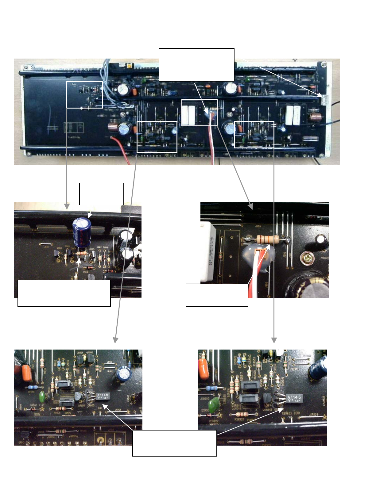
AVR7000 2CH AMP 01-12-01.
Picture 1.
CN906 for CP905
short-circuit the wire one by
one to ground with the 330
ohm resistor
Picture 2. Picture 3.
Solder the 3K3 ohm and the 1000 uf
cap between J980 and J981
egative side of the cap to J980
Remember to
Glue the cap
10-12 Kohm from -78V
to ground
Picture 4. Picture 5.
ew transistors 2SA1370
(or 2SA1376)
Remember to glue them to the PCB
Page 3

N
AVR7000 3CH AMP 01-12-01.
Picture 6.
CN902 for CP901
short-circuit the wire one by
one to ground with the 330
ohm resistor
Picture 7. Picture 8.
ew transistors 2SA1370
(or 2SA1376)
Remember to glue them to the
PCB
Picture 9.
 Loading...