

Page 1
harman/kardon
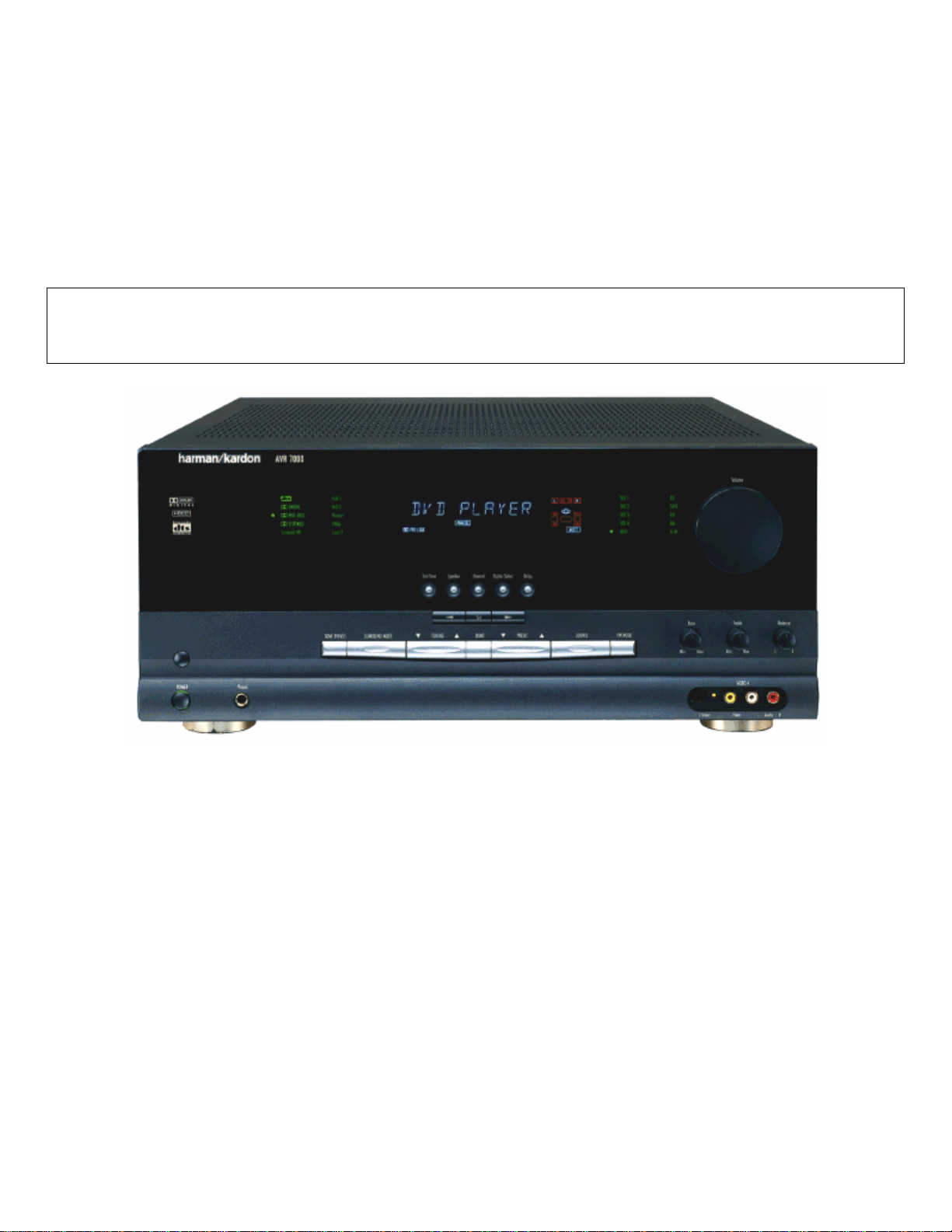
AVR7000
A/V DOLBY DIGITAL RECEI VER
SERVICE MANUAL
ESD WAR NIN G …………………..….……….2
LEAKAGE TESTING……………….…..…....3
BASIC SPECIFICATIONS…………………..4
DETAILED SPECIFICATIONS…….………..5
FRONT P A NEL C O NTR O L S ………..….…..13
REAR PANEL CONNECTIONS……..….… 15
REMOTE CONTROL FUNCTIONS……….17
SERVICE BULLETINS/TECH TIPS…...….20
IDLE CURRENT ADJUST…………….…...28
TUNER ALIGNMENT…………………..…..29
TROUBLESHOOTING GUIDE…...…….…32
PROCESSOR RESET……………………..32
UNIT EXPLOD ED VIEW……………………33
250 Crossways Park Dr.
Woodbur y, New York 11797 Rev4 – 7/ 2005
CONTENTS
EXPLODED VIEW PARTS LIST………….34
BLOCK DIAGRAM……………….…………35
PCB DRAWINGS……………….……..……36
MECHANICAL PARTS LIST………..………52
PAC K A G ING P A RTS LIST………....………54
REVISIONS - ELECTRICAL PARTS LIST.55
ELECTRICAL PARTS LIST…….………….56
SEMICONDUCTOR PINOUTS……..….….76
SCHEMATICS…………………..…..……..137
AVR7000 TRANSFORMER………..…….161
WIRING DIAGRAM………………………..162
PACKAGE……………………...……...…..163
harman/kardon, Inc.
Page 2
AVR7000 harman/kardon
2
Some semiconductor (solid state) devices can be damaged easily by static electricity. Such components commonly are called
Electrostatically Sensitive (ES) Devices. Examples of typical ES devices are integrated circuits and some field effect transistors and
semiconductor "chip" components.
The following techniques should be used to help reduce the incidence of component damage caused by static electricity.
1. Immediately before handling any semiconductor component or semiconductor-equipped assembly, drain off any electrostatic charge on
your body by touching a known earth ground. Alternatively, obtain and wear a commercially available discharging wrist strap device,
which should be removed for potential shock reasons prior to applying power to the unit under test.
2. After removing an electrical assembly equipped with ES devices, place the assembly on a conductive surface such as aluminum foil, to
prevent electrostatic charge build-up or exposure of the assembly.
3. Use only a grounded-tip soldering iron to solder or unsolder ES devices.
4. Use only an anti-static solder removal device. Some solder removal devices not classified as "anti-static" can generate electrical charges
sufficient to damage ES devices.
5. Do not use freon-propelled chemicals. These can generate electrical change sufficient to damage ES devices.
6. Do not remove a replacement ES device from its protective package until immediately before you are ready to install it. (Most replacement
ES devices are packaged with leads electrically shorted together by conductive foam, aluminum foil or comparable conductive material.)
7. Immediately before removing the protective material from the leads of a replacement ES device, touch the protective material to the
chassis or circuit assembly into which the device will be installed.
CAUTION :
8. Minimize bodily motions when handling unpackaged replacement ES devices. (Otherwise harmless motion such as the brushing together
or your clothes fabric or the lifting of your foot from a carpeted floor can generate static electricity sufficient to damage an ES devices.
Be sure no power is applied to the chassis or circuit, and observe all other safety precautions.
Each precaution inthis manualshould be followed during servicing.
Components identified with the IEC symbol in the parts list are special significance to safety. When replacing a component identified with
, use only the replacement parts designated, or parts with the same ratings or resistance, wattage, or voltage that are designated in the
parts list in this manual. Leakage-current or resistance measurements must be made to determine that exposed parts are acceptably
insulated from the supply circuit before retuming the product to the customer.
Page 3
AVR7000 harman/kardon
3
Before returning the unit to the user, perform the following safety checks :
1. Inspect all lead dress to make certain that
leads are not pinched or that hardware is not
lodged between the chassis and other metal
parts in theunit.
2. Be sure that any protective devices such as
nonmetallic control knobs, insulating fish-
papers, cabinet backs, adjustment and
compartment covers or shields, isolation
resistor-capacity networks, mechanical
insulators, etc. Which were removed for the
servicing are properlyre-installed.
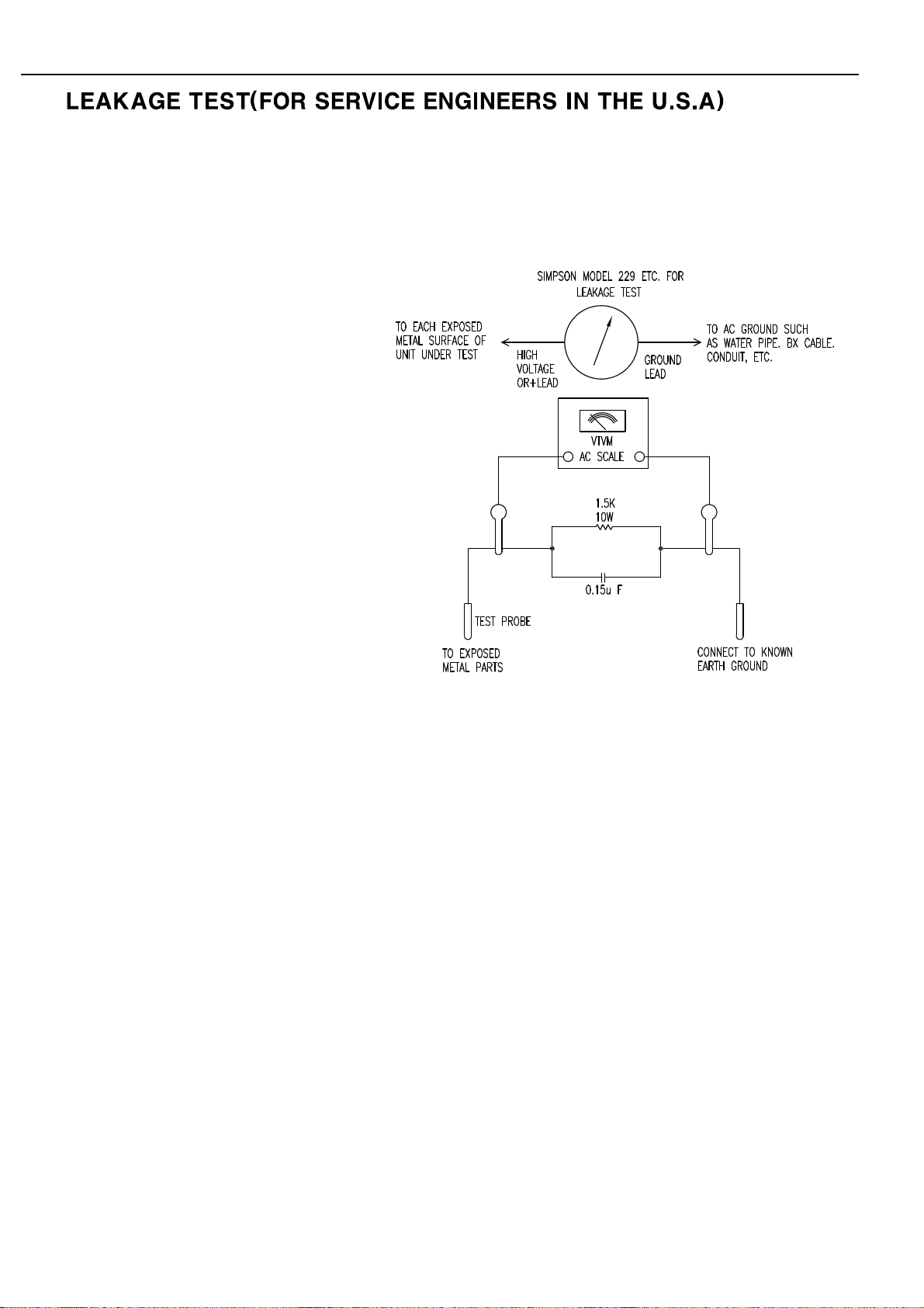
3. Be sure that no shock hazard exists ; check for leakage
current usingSimpson Model 229 Leakage Tester, standard
equipment item No. 21641, RCA Model WT540A or use
alternate method as follows : Plug the power cord directly
Into a 120 volt AC receptacle (do not use an Isolation
Transformer for this test). Using two clip leads, connect a
1500 ohms,10watt Resistor paralleledby a 0.15uFcapacitor,in series withall exposed metalcabinet parts anda known earthground, such
as a water pipe or conduit. Use a VTVM or VOM with 1000 ohms per volt, or higher sensitivity to measure the AC voltage drop across the
resistor. (See diagram) Move the resistor connection to each exposed metal part having a return path to the chassis (antenna, metal,
cabinet, screwheads, knobsand controlshafts, escutcheon, etc.) andmeasure theAC voltage drop acrossthe resistor. (Thistest should be
performed withthe 0.35 volt RMS or more is excessive and indicates a potential shockhazard which must be correctedbefore returning the
unit to theowner.
Page 4

TECHNICAL SPECIFICATIONS
Technical Specifications
Audio Section
Stereo Mode
Continuous Average Power (FTC)
110 Watts per channel, 20Hz–20kHz,
@ < 0.07% THD, both channels driven into 8 ohms
Five-Channel Surround Modes
Power Per Individual Channel
Front L&R channels:
100 Watts per channel,
@ < 0.07% THD, 20Hz–20kHz into 8 ohms
Center channel:
100 Watts,@ < 0.07% THD,20Hz–20kHz into 8 ohms
Surround channels:
100 Watts per channel,
@ < 0.07% THD, 20Hz–20kHz into 8 ohms
Input Sensitivity/Impedance
Linear (High Level) 200mV/47kohms
Signal-to-Noise Ratio (IHF-A) 95dB
Surround System Adjacent Channel Separation
Analog Decoding 40dB
(Pro Logic, etc.)
Dolby Digital (AC-3) 55dB
DTS 55dB
Frequency Response
@ 1W (+0dB,– 3dB) 10Hz– 100kHz
High Instantaneous
Current Capability (HCC) ±75 Amps
Transient Intermodulation
Distortion (TIM) Unmeasurable
Rise Time 16µsec
Slew Rate 40V/µsec
FM T uner Section
Frequency Range 87.5–108MHz
Usable Sensitivity IHF 1.3 µV/ 13.2dBf
Signal-to-Noise Ratio Mono/Stereo 70/68dB
Distortion Mono/Stereo 0.2/0.3%
Stereo Separation 40dB @ 1kHz
Selectivity ±400kHz,65dB
Image Rejection 80dB
IF Rejection 90dB
Tuner Output Level 1kHz, ±75kHz Dev 500mV
AM T uner Section
Frequency Range 520–1720kHz
Signal-to-Noise Ratio 45dB
Usable Sensitivity Loop 500 µV
Distortion 1kHz, 50% Mod 0.8%
Selectivity ±10kHz,30dB
Video Section
Video Format NTSC
Input Level/Impedance 1Vp-p /75 ohms
Output Level/Impedance 1Vp-p/ 75 ohms
Video Frequency 5Hz–10MHz (–3dB)
Response
General
Power Requirement AC 120V/60Hz
Power Consumption 125W idle, 1100W maximum
(2 channels driven)
Dimensions (Max)
Width 17.3 inches (440mm)
Height 7.62 inches (193mm)
Depth 20.43 inches (519mm)
Weight 49 lb (22.3 kg)
Depth measurement includes knobs,buttons and terminal connections.
Height measurement includes feet and chassis.
All features and specifications are subject to change without notice.
Harman Kardon is a registered trademark,and Power for the digital revolution is a
trademark,of Harman International Industries, Inc.
*Manufactured under license from Dolby Laboratories.
“Dolby,”“Pro Logic,”“AC-3”and the Double-D symbol are
trademarks of Dolby Laboratories.Confidential Unpublished
Works.©1992 –1999 Dolby Laboratories, Inc. All rights reserved.
†
DTS and DTS Surround are trademarks of Digital Theater Systems,Inc.
††
UltraStereo is a trademark of UltraStereo Corp.
VMAx is a trademark of Harman International Industries,Inc., and is an
implementation of Cooper Bauck Transaural Stereo under patent license.
Logic 7 is a registered trademark of Lexicon,Inc.
HDCD is a registered trademark of Pacific Microsonics.
Crystal is a registered trademark of Cirrus Logic Corp.
AVR7000 harman/kardon
4
Page 5

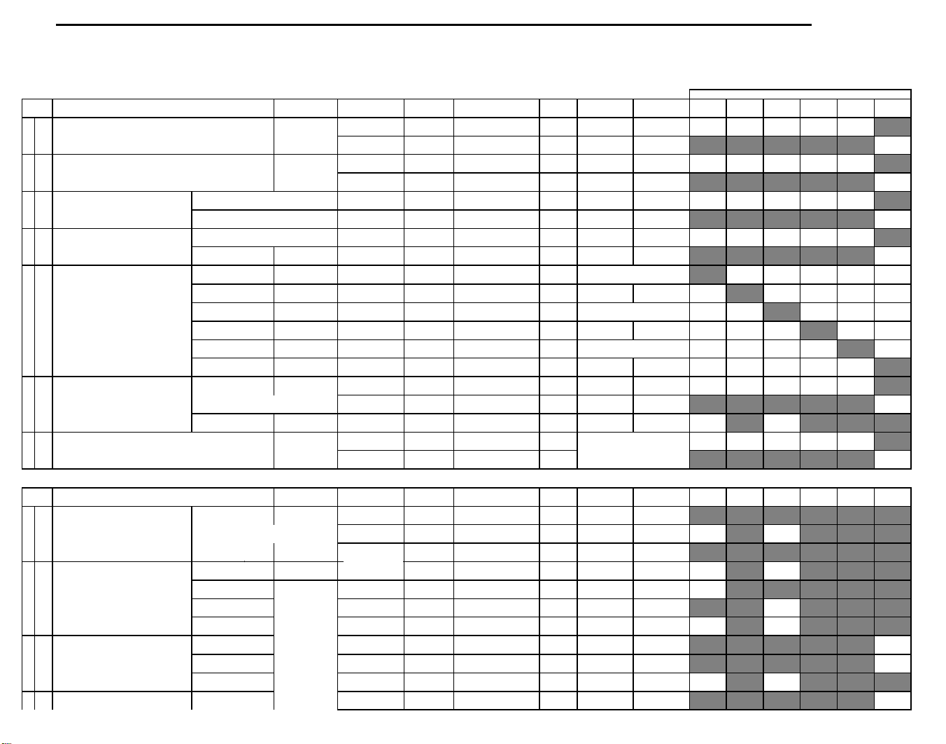
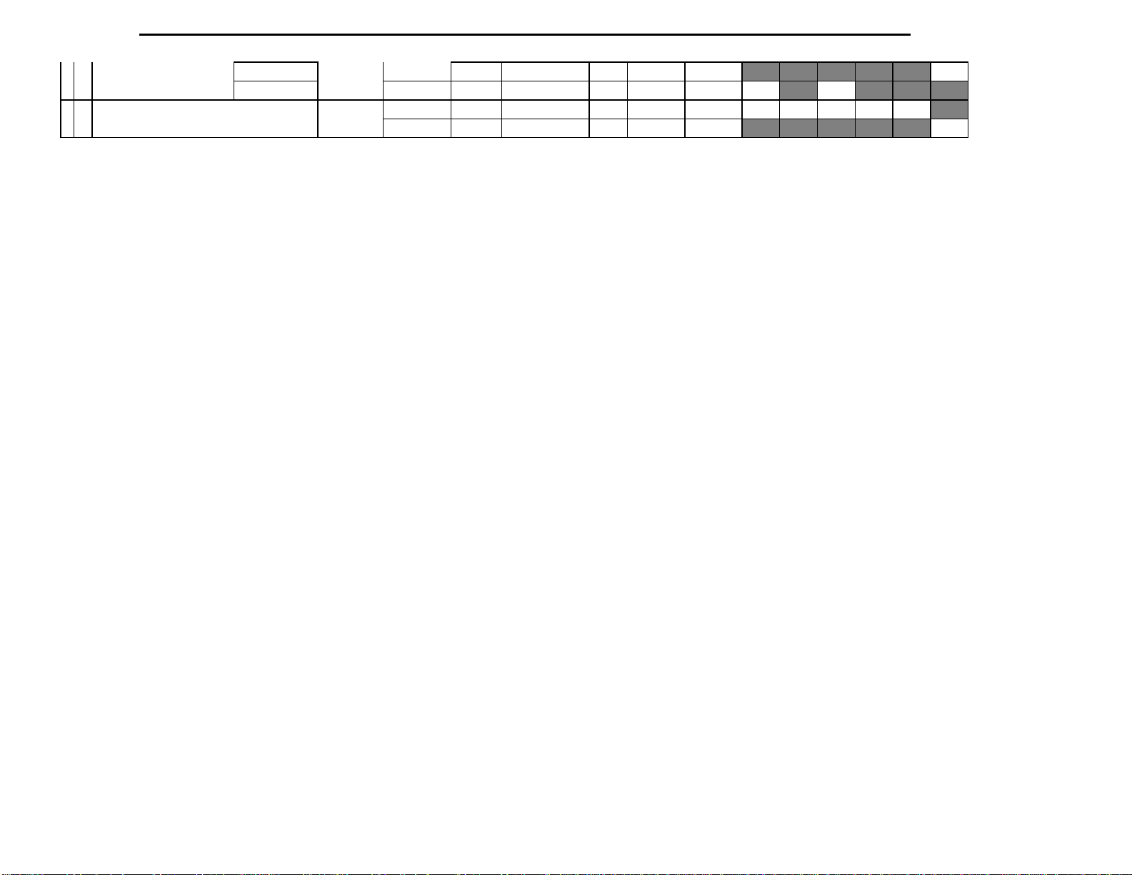
DETAILED SPECIFICATION FOR RECEIVER AVR7000 (120V)
PARAMETERS
Power supply : 120 V , 60 Hz
FRONT AMP SECTION
NO
DESCRIPTION
Y/N
INPUT
FREQ.
REMARK
UNIT
LIMIT
NOMINAL
2
CHANNEL BALANCE
Y
Vin=100mV, Vol at Max TO -40dB
dB below rated Power current level. 20-
Inputs
Kohm
VOL at max. 10Hz-22KHz BW, RMS ,
VOL at max. 10Hz-22KHz BW, RMS ,
'A Weighted', all inputs terminated w/ 1
VOL at max. 10Hz-22KHz BW, RMS ,
VOL at max. 10Hz-22KHz BW, RMS,
VOL at max. 10Hz-22KHz BW, RMS,
'A Weighted', all inputs terminated w/ 1
VOL at max. 10Hz-22KHz BW, RMS,
Ohm load, Fl and FR driven.
AVR7000 harman/kardon
5
Measuring methods are based on IHF and IEC standard 268-3
Measurement conditions,unless otherwise noted :
Output resistive load = (8) ohms / All channels loaded.
Tone Off or Tone(Bass,Treble), Balance, EQ control : Center Position , Other SW's : OFF, Volume:Max
Nominal input level : 200mV for general purpose inputs
Power figures should be kept minimum 10min., between 15 and 35 oC
Terminator : 1kohm for general purpose inputs
All Voltage Measurements are made with RMS detector, unless otherwise specified.
Filter : IHF-A filter
R/O = Rated Output, which is 100 W into 8 ohm resistive load, for both Stereo and 6 CH DIRECT inputs.
UUT= Unit Under Test.
.
D
1
INPUT SENSITIVITY Y CD 1kHz To obtain rated Power mV 200+/-30
Y 6 CH DIRECT 1kHz To obtain rated Power mV
6 CH DIRECT 1kHz
Y 1kHz Vin=100mV, Volt at -40 TO -60dB dB +/-6 +/-4
3
DAMPING FACTOR Y 6 CH DIRECT 1kHz
4
HICC Y 6 CH DIRECT 10 KHz
5 RESIDUAL NOISE Y
RESIDUAL NOISE Y 6 CH DIRECT 1kHz
Should be met
by all Stereo
Should be met
Y
by all Stereo
Inputs
Should be met
Y
by all Stereo
Inputs
Should be met
Y
by all Stereo
Inputs
Should be met
Y
by all Stereo
Inputs
Y 6 CH DIRECT 1kHz
*SUB-WOOFER SPKR:NO *SPKR LEVEL:ALL 0dB
Zout at a current level equivalent to 10
20kHz, 8 ohm load
10 KHz single cycle sine impulse. 1
impulse/sec. Using 0.1 ohm, 1%, 250
W, non inductive load
VOL at min. 10Hz-22KHz BW, peak
1kHz
detector, all inputs terminated w/ 1
VOL at max. 10Hz-22KHz BW, peak
1kHz
detector, all inputs terminated w/ 1
1kHz
non-weighted, all inputs terminated w/
1kHz
1kHz
'A Weighted', all inputs left un-
VOL at min. 10Hz-22KHz BW, peak
detector, all inputs terminated w/ 1
VOL at max. 10Hz-22KHz BW, peak
detector, all inputs terminated w/ 1
Kohm
1 Kohm
Kohm
terminated
Kohm
Kohm
dB +/-3 +/-2
A >60
mVpk
mVpk
mVrms
mVrms
mVrms
mVpk
mVpk
>100
<1.2mV
<3mVrms
<1mVrms
<0.7mVrms
<0.7mVrms
<1.2mVrms
<3mVrms
200+/-20
>65
<1.0mV
<1.5mVrms
<0.75mVrms
<0.5mVrms
<0.5mVrms
<1.0mVrms
<1.5mVrms
Y 6 CH DIRECT 1kHz
Y 6 CH DIRECT 1kHz
Y 6 CH DIRECT 1kHz
6
TOTAL HARMONIC
DISTORTION
TOTAL HARMONIC
DISTORTION
TOTAL HARMONIC
DISTORTION
TOTAL HARMONIC
DISTORTION
CONTINUOUS AVERAGE
7
POWER: A) Stereo, 8
Should be met
Y
by all Stereo
Inputs
Y 6 CH DIRECT
Should be met
Y
by all Stereo
Inputs
Y 6 CH DIRECT
Y CD 20 Hz
Y CD 1kHz
20Hz-20 KHz, Power
out =Rated Power - 1 dBVol at Max, 10 Hz-80KHz Meas BW. % <0.08
20Hz-20 KHz, Power
out =Rated Power - 1 dBVol at Max, 10 Hz-80KHz Meas BW. % <0.08
20Hz-10 KHz, Power
out =1 W
20Hz-10 KHz, Power
out =1 W
non-weighted, all inputs terminated w/
Vol at Max, 10 Hz-22 KHz Meas BW. % <0.08
Vol at Max, 10 Hz-22 KHz Meas BW. % <0.08
measurement BW. Volume at Max.
measurement BW. Volume at Max.
1 Kohm
Kohm
'A Weighted', all inputs left un-
terminated
at 0.1% THD, 10 Hz-80 KHz
at 0.1% THD, 10 Hz-80 KHz
mVrms
mVrms
mVrms
W >110
W >110
<1mVrms
<0.7mVrms
<0.7mVrms
<0.75mVrms
<0.5mVrms
<0.5mVrms
<0.05
<0.05
<0.05
<0.05
>115
>115
Page 6

Y CD 20 KHz
Kohm.
CHANNEL SEPARATION:
CHANNEL SEPARATION:
channel individually. Undriven channels
Stereo and 6 CH
input, to obtain R/O-3dB at the speaker
6
CONTINUOUS AVERAGE
POWER: B) All 5
Channels Driven, 8 ohms
8 IMD(SMPTE) Y 6 CH DIRECT
9 DIM Y 6 CH DIRECT
10
S/N RATIO,IHF-A FILTER Y All Stereo Inputs 1kHz
Y 6 CH DIRECT 20 Hz
Y 6 CH DIRECT 1kHz
Y 6 CH DIRECT 20 KHz
Sine wave # 1 f
=60Hz. Ampl=4, sine
wave # 2 f= 7 KHz.
Square wave f
=3.15KHz. Ampl=4,
sine f=15 KHz.
Y All Stereo Inputs 1kHz
Y All Stereo Inputs 1kHz
Y 6 CH DIRECT 1kHz
Ampl=1
Ampl=1
at 0.1% THD, 10 Hz-80 KHz
measurement BW.Volume at Max.
at 0.1% THD, 10 Hz-80 KHz
measurement BW.Volume at Max.
at 0.1% THD, 10 Hz-80 KHz
measurement BW.Volume at Max.
at 0.1% THD, 10 Hz-80 KHz
measurement BW.Volume at Max.
30 step Sweep of Gen to Drive to Pk-
Pk value of sine rated power
30 step Sweep of Gen to Drive to Pk-
Pk value of sine rated power
Referred to Rated Output Power, Vol
at max, all inputs terminated w/ 1
Referred to 1W Out. Vol at max, all
Referred to Rated Output Power, Vol
at max, all inputs left un-terminated
Referred to Rated Output Power, Vol
at max, all inputs terminated w/ 1
Kohm.
inputs terminated w/ 1 Kohm.
W >110
W >100
W >100
W >100
% < 0.15 < 0.09
% < 0.15 < 0.09
dB >92
dB >72
dB >92
dB >92
>115
>105
>105
>105
>95
>75
>95
>95
11
Zterm = 1KW/1000pF
Zterm = 1KW/1000pF
12 FUNCTION CROSSTALK,
(Measured on all Channels)
Y 6 CH DIRECT 1kHz
Y 6 CH DIRECT 1kHz
Y CD 100Hz
Y 1kHz
Y 10kHz
Y 6 CH DIRECT 100Hz
Y 1kHz
Y 10kHz
All Analog
Y
DIRECT Inputs
1 kHz
Referred to Rated Output Power, Vol
at max, all inputs left un-terminated.
Referred to 1W Out. Vol at max, all
inputs terminated w/ 1 Kohm.
Vol at Max, Gen amplitude adjusted to
obtain R/O-3dB, measured w/ AP's
Xtalk mode. Driving every channel
individually. Undriven channels should
be terminated w/ 1 kOhm.
Vol at Max, Gen amplitude adjusted to
obtain R/O-3dB, measured w/ AP's
Xtalk mode. Driving every channel
individually. Undriven channels should
be terminated w/ 1 kOhm.
Vol at Max, Gen amplitude adjusted to
obtain R/O-3dB, , measured w/ AP's
Xtalk mode. Driving every channel
individually. Undriven channels should
be terminated w/ 1 kOhm.
Vol at Max, Gen amplitude adjusted to
obtain R/O-3dB, measured w/ AP's
Xtalk mode. Driving every channel
individually. Undriven channels should
be terminated w/ 1 kOhm.
Vol at Max, R/O-3dB, measured w/
AP's Xtalk mode. Driving every
should be terminated w/ 1 kOhm.
Vol at Max, Gen amplitude adjusted to
obtain R/O-3dB, , measured w/ AP's
Xtalk mode. Driving every channel
individually. Undriven channels should
be terminated w/ 1 kOhm.
Volume at Max. Apply Sinewave
Signal Gen amplitude to the tested
outputs. Record the output level as the
reference output. Then, scroll thru the
other possible stereo inputs, and
measure the output level. Compute t
dB >92
dB >74
dB >65
dB >65
dB >55
dB >65
dB >65
dB >55
dB >70
>95
>77
>70
>70
>65
>70
>70
>65
>75
Page 7

Y
Stereo and 6 CH
input, to obtain R/O-3dB at the speaker
outputs. Record the FL and FR speaker
Apply an FM Stereo RF input thru a 50-
Full scale Digital
FTC POWER 20Hz~20kHz,
FREQUENCY RESPONSE (-
Stereo and 6 CH
Volume at Max. Drive channel to R/O.
Then sweep frequency until finding 1 %
Ratio of freq @ 1 % THD+N / 20 KHz
is the Slew Factor
7
DIRECT Inputs
AM/FM Tuner
Y
All Analog
Input
Volume at Max. Apply Sinewave
Signal Gen amplitude to the tested
10 kHz
output level as the reference output.
Scroll thru other stereo inputs, and
measure the output level. Compute th
>75 ohm dummy antenna (98 MHz
carrier, 75 KHz modulation, 1 KHz
tone, 72 dBuV level). Then set UUT to
1 KHz
FM Stereo , 98 MHz. Set Volume
control to 10 dB below Max. Record
the FL and FR speaker output level as
the refere
dB > 55
>75
Input
1 hour preconditioning by driving all
19
0.08 % THD, 8 ohm load
DYNAMIC POWER
21
OUTPUT
22
3dB)
POWER BANDWIDTH -
23
3dB
24 SLEW RATE Y CD 20 KHz Square Wave
25 SLEW-FACTOR Y
26 INPUT IMPEDANCE Y
27 HEADPHONE OUTPUT Y CD 1kHz Volume at Max mV 1.2 +/- 0.4 1.2 +/- 0.2
H/P = 32ohms (200)mV 1kHz mV
Y CD 20 Hz-20 KHz
Y CD 1kHz
All Analog
Y
DIRECT Inputs
Y CD THD 0.08% Hz~kHz 20-60Khz
6 CH
DIRECT/ALL
STEREO
INPUTS
6 CH
DIRECT/ALL
STEREO
INPUTS
1 KHz reference
channels to 1/3 rated power. 25 oC. 10
20 cycle burst- 480 msec off. Sweep
Ref to 1W, 1KHz Hz 10 Hz-100 KHz
Drive unit to 40 Vpp. Mesure delta
amplitude and delta time. Compute
THD+N reading. Record frequency.
1kHz kohm 47 Kohm
TBD
Hz-80KHz Meas BW.
ACV=117VRMS, 60 Hz
ampl to reach clipping point.
V/usec
W >100
W >130
V/usec >12
>105
> 135
5 Hz-150 KHz
>13
>5
>5.5
Page 8

COMPONENT VIDEO
AVR7000 harman/kardon
8
3 S/N RATIO VCR1(1Vp-p) 1MHz dB 40
1 OUTPUT LEVEL at 75ohms
"Y" LEVEL(GREEN) VCR1(1Vp-p) 1 +/- 20mV
"Cb" LEVE(BLUE) VCR1(0.678Vp-p) Vp-p 0.678+/-10mV 0.678+/-5mV
"Cr" LEVE(RED) VCR1(0.678Vp-p) 0.678+/-10mV 0.678+/-5mV
45
1 +/- 10mV
Page 9

TUNER SECTION
Measuring methods in confirmity with IEC standard 315
Measurements condition FM : Radio frequency = 98.1MHz, Audio frequency = 1kHz
Reference level = 1mV on ( 75ohms , 300ohms )
Deviation : MONO = ?5kHz, Stereo = ?7.5kHz?.5kHz
MONO = ?0kHz, Stereo = ?0kHz?.5kHz
Test Point : TP 1 = 90.1MHz, TP 2 = 98.1MHz, TP 3 = 106.1MHz
Filter = B.P.F at STEREO
FM SECTION
NO
DESCRIPTION
UNIT
LIMIT L/R
NOMINAL L/R
MEAS.
NEEDED
TUNING RANGE LOW ~ HIGH MHz
AM SECTION
Measuring methods in confirmity with IEC standard 315
Measurements condition AM - MW : Radio frequency = 1000/999kHz, Audio frequency = 400Hz
LW : Radio frequency = 207kHz, Audio frequency = 400Hz
Reference level = 5mV/m,10mV/m on 50ohms
Modulation = 30%
Test Point : MW
TP1 = (600)kHz
TP2 = (1000)kHz
TP3 = (1400)kHz
LW TP1 = 162kHz, TP2 = 207kHz, TP3 = 252kHz
NO
DESCRIPTION
UNIT
LIMIT L/R
NOMINAL L/R
9
1
*
STEP AUTO/Man. kHz
*2USABLE SENSITIVITY TP 1 dBf
S/N = (26,30)dB
FULL LIMITING SENSE OUTPUT = -3dB dBf
3
*4AUTO STOP LEVEL dBf
*5AUTO SCAN ERROR kHz
*6S/N RATIO MONO dB
IHF-A FILTER STEREO dB
*7TOTAL HARMONIC DISTORTION MONO %
8 (50,46)dB QUIETING SENS.
*9CHANNEL SEPARATION 100Hz dB
FREQUENCY RESPONSE AT ?1,-3dB Hz
10
SPURIOUS RESPONSE dB
11
IF REJECTION TP 1 dB
12
IMAGE REJECTION TP 3 dB
13
AM REJECTION RATIO dB
14
RF INTERMODULATION dB
15
CAPTURE RATIO dB
16
ALTERNATIVE CH SELECTIVITY
17
*19OUPUT LEVEL MONO mV
TP 2 dBf
TP 3 dBf
STEREO %
MONO dBf
STEREO dBf
1kHz dB
10kHz dB
?(400)kHz
dB
AVR7000 harman/kardon
87.5~107.9M
100
> 17.2
> 17.2
> 17.2
> 15.2
33.2 +/- 6
+/- 15/20
> 65
> 63
> 0.5
> 0.8
> 23.2
> 48.3
> 35
> 40
> 30
20~15K
> 80
> 70
> 65
> 50
> 25.
> 65
500 +/- 150
> 14.2
> 14.2
> 14.2
> 12.2
33.2 +/- 5
+/- 20/25
> 70
> 68
> 0.3
> 0.5
> 20.2
> 45.3
> 40
> 45
> 35
10~15.3K
> 90
> 80
> 70
> 55
> 2
> 70
500 +/- 100
* 1 TUNING COVER RANGE LOW ~ HIGH MW kHz
LW kHz
STEP AUTO/Man. kHz
* 2 USABLE SENSITIVITY MW TP 1 uV/m
TP 2 uV/m
S/N = 20dB TP 3 uV/m
LW TP 1 uV/m
TP 2 uV/m
TP 3 uV/m
520~1710
> 800
> 800
> 800
10
> 500
> 500
> 500
Page 10

3 S/N RATIO MW dB
10
> 40
INPUT=10mV/m LW dB
4 TOTAL HARMONIC DISTORTION %
5 OVER LOAD DISTORTION 5mV 80% MOD %
6 FREQUENCY RESPONSE at -6dB MW Hz
> 1.5
> 10
100~2K
LW Hz
7 SELECTIVITY 10kHz/9kHz MW dB
> 20
LW dB
8 AGC FIGURE OF MERIT INPUT 100mV dB
9 IMAGE REJECTION MW = TP 3 dB
> 50
> 30
LW = TP 3 dB
10 WHISTLE MODULATION
INPUT = 1mV/m
2IF
3IF
%
%
> 15
> 15
11 AUTO STOP LEVEL MW uV/m 800 (+/- 6dB)
LW uV/m
* 12 TUNED LEVEL MW uV/m 800 (+/- 6dB)
LW uV/m
* 13 OUTPUT LEVEL mV
120 +/- 40
> 45
> 0.8
> 5
80~2.3K
> 25
> 55
> 35
> 10
> 10
800 (+/- 5dB)
800 (+/- 5dB)
120 +/- 30
Page 11
AC-3 SECTION
Measurements conditions,unless otherwise noted : Input Function : DVD
Digital Input Mode : OPTICAL1
Speker Mode : Front/Center/Surround:LARGE, Sub-Woofer:YES
Main Vol Position : 1 Vrms Output Position
Trim Vol Position : All "0 dB"
Test Point : Pre-Out
Test disc : DOLBY TEST DVD VERSION 1.0
Center, Rear delay : 0 ms
MEASUREMENT
PRE-OUT : 1V Unweighted
71(
65/6/7/8/9
:ref
)
Sub-woofer:NO
"
C-> L, R
Center 0dB
Main Vol level
Ls-> L
Ls 0dB Setting
Rs-> R
Rs 0dB Setting
SubWoofer -> L,
R
L/C/R/Ls/Rs ->
Sub Out
Main Vol level
L/C/R/Ls/Rs ->
Sub Out
C/Ls/Rs -> L, R
L:0dB C:No S:No
L/C/R/Ls/Rs/LFE-
> Sub Out (1)
AVR7000 harman/kardon
11
NO DESCRIPTION SIGNAL INPUT CHAPTER UNIT
* 1 Output Level 1kHz 0dB 65/6/7/8/9 V
Main Vol Level : "60"Position 30Hz 0dB 70 V
* 2 Output Level 1kHz 0dB 65/6/7/8/9 mV
at MIN.VOL. 30Hz 0dB 70 mV
* 3 S/N Ratio PRE-OUT : 100mV "A"Weighted 1kHz -20dB 33,34,35 dB
30Hz 0dB 32 dB
* 4 T.H.D PRE-OUT : 100mV 1kHz -20dB 6 %
PRE-OUT : 1V 30Hz 0dB 18 %
* 5 Channel Separation L 1kHz 0dB 65 dB
C 1kHz 0dB 66 dB
R 1kHz 0dB 67 dB
LS 1kHz 0dB 68 dB
RS 1kHz 0dB 69 dB
SW 30Hz 0dB 70 dB
* 6 Frequency Response Sub-woofer:YES 30Hz (1kHz) 0dB
at M-Vol Level:"60"
* 7 Dialog Normalization 1kHz 0dB 62 dB
Main Vol Level : "60"Position 100Hz 0dB 62 dB
1kHz (30Hz) 0dB 60 (71 :ref) dB
30Hz (1kHz) 0dB 72 (60 :ref) dB
NO DESCRIPTION SIGNAL INPUT CHAPTER UNIT
* 8 2CH Down Mix level AC-3 mode
Main Vol Level : Center/Surround :no 1kHz 0dB 38 dB
"60"Position Sub-woofer : NO
* 9 Channel across level
"60" Position
* 10 LFE Signal across level
"60" Position
* 11 LFE Signal across level
1kHz 0dB 66 dB
1kHz 0dB 68 dB
1kHz 0dB 69 dB
30Hz 0dB 70 dB
30Hz 0dB 71 V
30Hz 0dB 71 dB
30Hz 0dB 71 dB
30Hz 0dB 72 V
LIMIT NOMINAL
1.09 +/- 0.3 1.0 +/- 0.2
3.3 +/- 0.5 3.3 +/- 0.3
> 0.2 > 0.15
> 0.2 > 0.15
60 65
> 60 > 65
> 0.5 > 0.3
> 0.3 > 0.2
Other Channel
> 60 > 65
L <--> R
> 50 > 55
ALL <--> Sub-Woofer
> 30 > 35
dB
< - 15 < - 20
< - 30 < - 35
5.5 +/- 1.5 5.5 +/- 1
LIMIT NOMINAL
-3.0 +/- 0.5 -3.0 +/- 0.3
-3 +/- 1 -3 +/- 0.5
-3 +/- 1 -3 +/- 0.5
-3 +/- 1 -3 +/- 0.5
-4.5 +/- 2 -4.5 +/- 1
6 +/- 1.5 6 +/- 1.0
2.5 +/- 1 2.5 +/- 0.5
-3 +/- 1 -3 +/- 0.5
2.5 <+/- 0.8 2.5 <+/- 0.5
L C R LS RS SW
L C R LS RS SW
Page 12
Main Vol level
L/C/R/Ls/Rs/LFE -
>Sub Out
C/Ls/Rs/LFE ->
L, R :Sub: No
Main Vol Level :
"50" Position
AVR7000 harman/kardon
12
DIGITAL(AC3) Section
30Hz 0dB 72 dB
"60" Position
* 12 Dynamic Range
Sub-woofer : Yes 30Hz 0dB 70 dB
30Hz 0dB 72 dB
1KHz 0dB 60 dB
15 < +/- 2 15 < +/- 1
-6.5 < +/- 3 -6.5 < +/- 2
-22 < +/- 2 -22 < +/- 1
+/- 1 +/- 0.5
Page 13
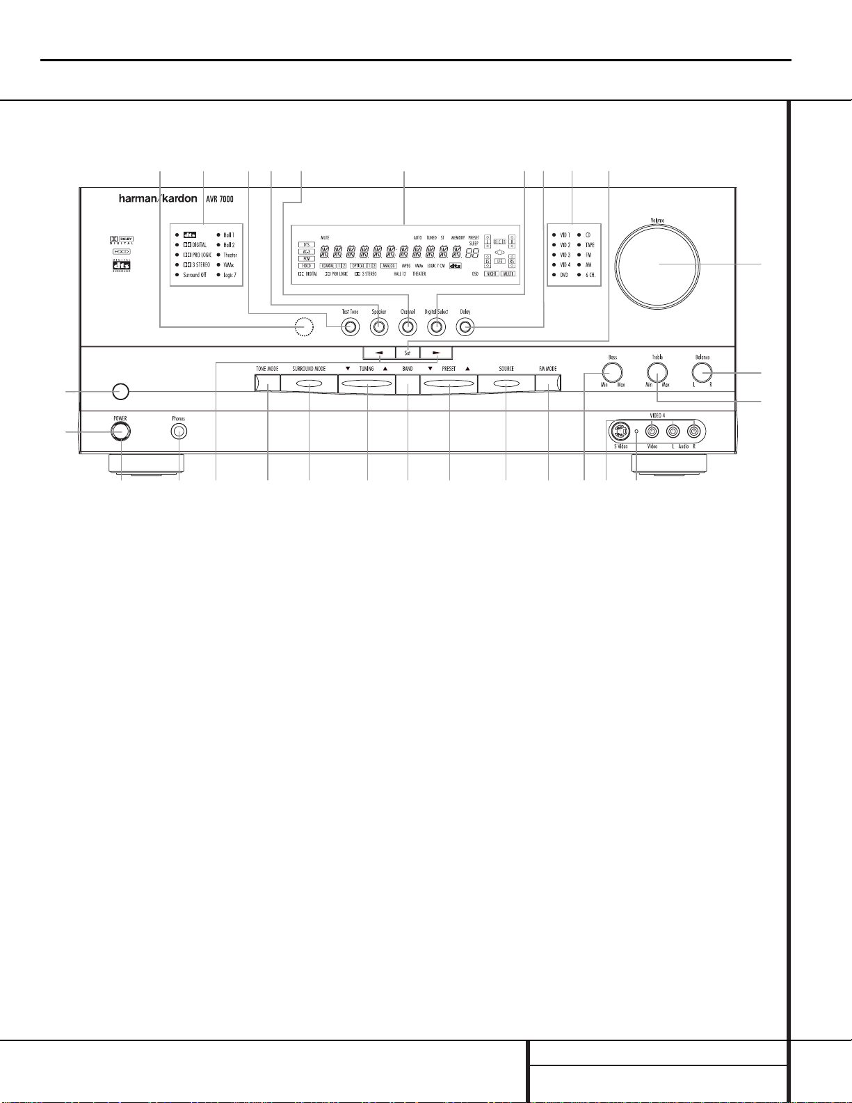
FRONT PANEL CONTROLS
1 Main Power Switch: Press this button to
apply power to the AVR 7000.When the
switch is pressed in, the unit is placed in a
Standby mode,as indicated by the amber LED
3 surrounding the System Power Control
2.This button MUST be pressed in to oper-
ate the unit.To turn the unit off and prevent
the use of the remote control, this switch
should be pressed until it pops out from the
front panel so that the word “OFF”may be
read at the top of the switch.
NOTE: In normal operation this switch is left in
the “ON” position.
2 System Power Control: When the Main
Power Switch1is “ON,”press this button
to turn on the AVR 7000; press it again to turn
the unit off.Note that the Power Indicator
surrounding the switch 3will turn green
when the unit is on.
3 Power Indicator: This LED will illuminate
in amber when the unit is in the Standby mode
to signal that the unit is ready to be turned on.
When the unit is in operation,the indicator will
turn green.
4 Headphone Jack: This jack may be used to
listen to the AVR 7000’s output through a pair of
headphones.Be certain that the headphones
have a standard
1
/4" stereo phone plug.Note
that the main room speakers will automatically
be turned off when the headphone jack is in use.
5 Selector Buttons: When you are establish-
ing the AVR 7000’s configuration settings, use
these buttons to select from the choices available,
as shown in the Information Display Ò.
6 Tone Mode: Pressing this button enables
or disables the Bass and Treble tone controls.
When the button is pressed so that the words
TONE IN appear in the Main Information
Display Ò, the settings of the Bass # and
Treble ^ controls will affect the output signals.When the button is pressed so that the
words TONE OUT appear in the Main
Information Display Ò, the output signal will
be “flat,” without any bass or treble alteration.
Front Panel Controls
1 Main Power Switch
2 System Power Control
3 Power Indicator
4 Headphone Jack
5 Selector Buttons
6 Tone Mode
7 Surround Mode Selector
8 Tuning Selector
9 Tuner Band Selector
) Preset Stations Selector
! Input Source Selector
@ FM Mode Selector
# Bass Control
$ Video 4 Input Jacks
% Video 4 Status Indicator
^ Treble Control
& Balance Control
* Volume Control
( Set Button
Ó Input Indicators
Ô Delay
Digital Input Selector
Ò Information Display
Ú Channel Select Button
Û Speaker Select Button
Ù Test Tone Selector
ı Surround Mode Indicators
ˆ Remote Sensor Window
9)
!
@#
$
%
^
&
Ó
3
45
67
8
1
2
(
*
Ô
Ò
Ú
Ûı
Ù
ˆ
AVR7000 harman/kardon
13
Page 14

FRONT PANEL CONTROLS
Front Panel Controls
7 Surround Mode Selector: Press this but-
ton to change the surround mode by scrolling
through the list of available modes.Note that
depending on the type of input, some modes
are not always available.(See page 25 for more
information about surround modes.)
8 Tuning Selector: Press the left side of the
button to tune lower frequency stations and the
right side of the button to tune higher frequency
stations.When a station with a strong signal is
reached, the TUNED indicator U will illuminate in the Information Display Ò .
To tune manually, tap the button lightly and
note that the tuner will step up one frequency
increment per button press.When the button is
held for a few seconds you will note that the
unit will quickly search the frequency band.
Release it once the fast tuning starts and the
tuner will automatically scan for the next station
with an acceptable signal and then stop.
9 Tuner Band Selector: Pressing this button
will automatically switch the AVR to the Tuner
mode.Pressing it again will switch between the
AM and FM frequency bands.(See page 29 for
more information on the tuner.)
) Preset Stations Selector: Press this but-
ton to select stations that have been entered
into the preset memory.(See page 29 for more
information on tuner programming.)
! Input Source Selector: Press this button
to change the input by scrolling through the list
of input sources.
@ FM Mode Selector: Press this button to
select Auto or Manual tuning.When the button
is pressed so that the AUTO Indicator V lights,
the tuner will search for the next station with an
acceptable signal when the Tuning Selector
8x
é
is pressed.When the button is
pressed so that the AUTO Indicator V is not lit,
each press of the Tuning Selector 8x
é
will increase the frequency.(See page 29 for
more information on using the tuner.)
# Bass Control: Turn this control to modify
the low frequency output of the left/right channels by as much as ±10dB.Set this control to a
suitable position for your taste or room acoustics.
$ Video 4 Input Jacks: These audio/video
jacks may be used for temporary connection to
video games or portable audio/video products
such as camcorders and portable audio players.
In normal use,they are an input that may be
selected by pressing the Input Source
Selector ! on the front panel, or the Video
4 Selector on either remote m
ç
.These
jacks may also be configured as an audio/video
output, that will make a dub of the currently
selected source when connected to an external
recorder or camcorder.To change the jacks from
their default setting as an input to an output,
use the Advanced Menu in the OSD system.
(See page 31 for more information on using the
Video 4 jacks as a record output.)
% Video 4 Status Indicator: This indicator
will normally be green to show that the Video 4
jacks are operating as an input source.When
the jacks have been configured as an output,
the indicator will turn red to show that they are
being used for recording. (See page 31 for
more information on using the Video 4 jacks.)
^ Treble Control:Turn this control to modify
the high frequency output of the left/right channels by as much as ±10dB.Set this control to a
suitable position for your taste or room acoustics.
& Balance Control: Turn this control to
change the relative volume for the front
left/right channels.
NOTE: For proper operation of the surround
modes this control should be at the midpoint
or “12 o’clock” position.
* Volume Control:Turn this knob clockwise
to increase the volume,counterclockwise to
decrease the volume.If the AVR is muted,
adjusting volume control will automatically
release the unit from the silenced condition.
( Set Button: When making choices during
the setup and configuration process,press this
button to enter the desired setting as shown
in the Information Display Ò into the
AVR 7000’s memory.The set button may also
be used to change the display brightness.
(See page 31.)
Ó Input indicators: A green LED will light in
front of the input that is currently being used as
the source for the AVR 7000.
Ô Delay: Press this button to begin the
sequence of steps required to enter delay time
settings.(See pages 20–21 for more information on delay times.)
Digital Input Selector: When playing a
source that has a digital output, press this
button to select between the Optical · and
Coaxial ° Digital inputs. (See pages 27–29
for more information on digital audio.)
Ò Information Display:This display deliv-
ers messages and status indications to help you
operate the receiver. (See pages 7–8 for a complete explanation of the Information Display.)
Ú Channel Select Button: Press this button
to begin the process of trimming the channel
output levels using an external audio source.
(For more information on output level trim
adjustment, see page 29.)
Û Speaker Select Button: Press this button
to begin the process of selecting the speaker
positions that are used in your listening room.
(See page 22 for more information on setup
and configuration.)
Ù T est Tone Selector: Press this button to
begin the process of adjusting the channel output levels using the internal test tone as a reference.(For more information on output level
adjustment, see page 23.)
ı Surround Mode Indicators: A green LED
will light in front of the surround mode that is
currently in use.
ˆ Remote Sensor Window: The sensor
behind this window receives infrared signals
from the remote control.Aim the remote at this
area and do not block or cover it unless an
external remote sensor is installed.
AVR7000 harman/kardon
14
Page 15

REAR PANEL CONNECTIONS
Rear Panel Connections
fl
‡
°
‹
¤
›
‚
¶§
fi
⁄
•
·
a
b
cdefghij
ª
£
™
¢¡∞
-
NOTE: For all video inputs and outputs f g
h i j, the same number is used to indicate
the audio,composite-video and S-Video connections related to that input.This accounts for the
same number appearing in more than one place
on the rear-panel drawing.
¡ AM Antenna
™ FM Antenna
£ 6-Channel Direct Inputs
¢ CD Inputs
∞ Component Video Outputs
§ Video 2 Component Video Inputs
¶ DVD Component Video Inputs
• Tape Inputs
ª Speaker Outputs
‚ Tape Outputs
⁄ Amplifier Inputs
¤ Unswitched AC Accessory Outlet
‹ Switched AC Accessory Outlets
› AC Power Cord
fi Subwoofer Output
fl Preamp Outputs
‡ Digital Audio Outputs
° Coaxial Digital Inputs
· Optical Digital Inputs
a Remote IR Output
b Multiroom IR Input
c Remote IR Input
d Multiroom Outputs
e Video Monitor Outputs
f Video 3 Inputs
g Video 2 Inputs
h Video 1 Outputs
i Video 1 Inputs
j DVD Inputs
AVR7000 harman/kardon
15
Page 16

REAR PANEL CONNECTIONS
Rear Panel Connections
¡ AM Antenna: Connect theAM loop antenna
supplied with the receiver to these terminals.If an
externalAM antenna is used, make connections
to the AM and GND terminals inaccordance
with the instructions supplied with the antenna.
™ FM Antenna: Connect the supplied indoor or
the optional external FM antenna to this terminal.
£ 6-Channel Direct Inputs: If an external
digital audio decoder is used, connect the outputs of that decoder to these jacks.
¢ CD Inputs: Connect these jacks to the out-
put of a compact disc player or CD changer.
∞ Component Video Outputs: Connect
these outputs to the component video inputs of
a video projector or monitor.When a source
connected to one of the two Component
Video Inputs §¶ is selected the signal will
be sent to these jacks.
§ Video 2 Component Video Inputs:
Connect the Y/Cr/Cb component video outputs
of a set top converter box or other video product to these jacks.
¶ DVD Component Video Inputs:Connect
the Y/Cr/Cb component video outputs of a DVD
player to these jacks.
• Tape Inputs: Connect these jacks to the
PLAY/OUT jacks of an audio recorder.
ª Speaker Outputs: Connect the these
jacks to the matching + or – terminals on your
speakers. When making speaker connections,
always make certain to maintain correct polarity
by connecting the red (+) terminals on the AVR
to the red terminals on the speaker and the
black (–) terminals on the AVR to the black terminals on the speakers.(See page 15 for more
information on speaker polarity.)
‚ Tape Outputs: Connect these jacks to the
RECORD/INPUT jacks of an audio recorder.
⁄ Amplifier Inputs: When the jumper pins
that link the Preamp Outputs fl with these
inputs are removed, these jacks may be used to
connect an external source or the AVR7000’s
multiroom system to the internal amplifiers.
(See page 17 for more information on using
these connections.)
¤ Unswitched AC Accessory Outlet: This
outlet may be used to power any AC device.
The power will remain on at this outlet regardless of whether the AVR 7000 is on or off.
‹ Switched AC Accessory Outlets: These
outlets may be used to power any device that
you wish to have turn on when the unit is
turned on with the System Power Control
switch 2.
› AC Power Cord: Connect the AC plug to
an unswitched AC wall output.
fi Subwoofer Output: Connect this jack to
the line-level input of a powered subwoofer. If
an external subwoofer amplifier is used, connect this jack to the subwoofer amplifier input.
fl Preamp Outputs: When the jumper pins
that link the Amplifier Inputs ⁄ with these
outputs are removed, these jacks may be connected to an external power amplifier.
‡ Digital Audio Outputs: Connect these
jacks to the matching digital input connector
on a digital recorder such as a CD-R or
MiniDisc recorder.
° Coaxial Digital Inputs: Connect the coax
digital output from a DVD player, HDTV receiver,
LD player or CD player to these jacks.The signal
may be either a Dolby Digital signal, DTS signal
or a standard PCM digital source.
· Optical Digital Inputs: Connect the opti-
cal digital output from a DVD player, HDTV
receiver, LD player or CD player to these jacks.
The signal may be either a Dolby Digital signal,
a DTS signal or a standard PCM digital source.
a Remote IR Output: This connection per-
mits the IR sensor in the receiver to serve other
remote controlled devices.Connect this jack to
the “IR IN”jack on Harman Kardon or other
compatible equipment.
b Multiroom IR Input: Connect the output of
an IR sensor in a remote room to this jack to
operate the AVR 7000’s multiroom control system.
c Remote IR Input: If the AVR 7000’s
front-panel IR sensor is blocked due to cabinet
doors or other obstructions,an external IR
sensor may be used. Connect the output of
the sensor to this jack.
d Multiroom Outputs: Connect these jacks
to the optional audio power amplifiers or video
display devices to view and listen to the source
selected by the mulitroom system in a remote
room.
e Video Monitor Outputs: Connect this jack
to the composite or S-Video input of a TV monitor or video projector to view the on-screen
menus and the output of any standard video
source selected by the receiver’s video switcher.
f Video 3 Inputs: Connect these jacks to the
audio and video outputs of a TV tuner, Cable TV
converter box, satellite receiver or another
audio/video source.
g Video 2 Inputs: Connect these jacks to the
audio and video outputs of a TV Tuner, Cable TV
converter box, satellite receiver or any other
audio/video source.
h Video 1 Outputs: Connect these jacks to
the audio and video RECORD/INPUT jacks of
a VCR.
i Video 1 Inputs: Connect these jacks to the
audio and video PLAY/OUT jacks of a VCR.
j DVD Inputs: Connect the analog audio
outputs and composite video output of a DVD
or LD player to these jacks.
AVR7000 harman/kardon
16
Page 17

MAIN REMOTE CONTROL FUNCTIONS
●
●
●
●
●
●
●
●
Main Remote Control Functions
AVR 7000
MULTI-ROOMNIGHT
kardon
SLEEP
SURR.
CH.
SET
SPKR
MENU
SAT
AVR
ON
POWER
CH.
TEST
harman
CD
PREV.CH.
DELAY
5
0
43
9
DIRECT
8
LIGHT
M3 M4
CLEAR
DWN-PRESET-UP
DIGITAL
21
6 CH.
76
OSD
M1
MEMORY
M2
a
k
m
o
b
l
n
p
s
d
f
j
i
r
`
z
28
29
30
31
34
32
x
q
t
u
w
y
v
33
35
c
e
g
g
h
TAPE
DVD
T/V
MUTE
GUIDE
EXIT
VID 4
VID 3
VID 2
VID 1
AM/FM
TUN-M
DWN-TUNING-UP
VOL.
VCRTV
CBL
a Program Indicator
b AVR Selector
c CD/Tape/DVD Input Selectors
d Power Off Button
e Test Tone
f Mute
g
⁄/¤
Buttons
h Channel Select Button
i Set Button
j
‹
Button
k Digital Select
l 6-Ch. Direct Input
m Video Input Selectors
n AM/FM Tuner Select
o Tuner Mode
p Memory Button
q Numeric Keys
r Macro 1/2 Buttons
s OSD Button
t Light Button
u Direct/Macro 3 Button
v Clear/Macro 4 Button
w Preset Up/Down
x Tuning Up/Down
y Forward/Reverse T ransport Buttons
z Night Mode
` Multi-Room
28
Delay/Prev.Ch.
29
›
Button
30
Speaker Select
31
Surround Mode Selector
32
Volume Up/Down
33
Sleep Button
34
Video Remote Selectors
35
IR Tr ansmitter Window
NOTE:The function names shown here are each
button’s feature when used with the AVR. Most
buttons have additional functions when used
with other devices.See page 38 for a list of
these functions.
17
AVR7000 harman/kardon
Page 18

MAIN REMOTE CONTROL FUNCTIONS
Main Remote Control Functions
IMPORTANT NOTE:The AVR 7000’s remote
may be programmed to control up to eight
devices,including the AVR 7000.Before using
the remote,it is important to remember to press
the Device Control Selector button bc
that corresponds to the unit you wish to
operate.In addition, the AVR 7000’s remote
is shipped from the factory to operate the
AVR 7000and most Harman Kardon CD or DVD
players and cassette decks.The remote is also
capable of operating a wide variety of other
products using the control codes that are part
of the remote.Before using the remote with
other products,follow the instructions on pages
34–45 to program the proper codes for the
products in your system.
It is also important to remember that many of
the buttons on the remote take on different
functions,depending on the product selected
using the Device Control Selectors.The descriptions shown here primarily detail the functions
of the remote when it is used to operate the
AVR 7000.(See page 38 for information about
alternate functions for the remote’s buttons.)
a Program Indicator:This three-color indi-
cator is used to guide you through the process
of learning commands from a remote into the
AVR’s remote code memory.(See page 35 for
information on learning IR codes.)
b AVR Selector: Pressing this button will
switch the remote so that it will operate the
AVR’s functions.If the AVR is in the Standby
mode,it will also turn the AVR on.
c CD/Tape/DVD Input Selectors:Pressing
one of these buttons will perform three actions
at the same time.First, if the AVR is not turned
on, this will power up the unit. Next, it will
select the source shown on the button as the
input to the AVR. Finally, it will change the
remote control so that it controls the device
selected.After pressing one of these buttons
you must press the AVR Selector button b
again to operate the AVR’s functions with the
remote.
d Power Off Button: Press this button to
place the unit in the Standby mode.Note that
this will turn off the main room functions,but
if the Multiroom system is activated,it will
continue to function.
e T est Tone: Press this button to begin the
sequence used to calibrate the AVR 7000’s output levels.(See page 23 for more information on
calibrating the AVR 7000.)
f Mute: Press this button to momentarily
silence the AVR 7000 or TV set being controlled, depending on which device has been
selected.
When the AVR 7000 remote is being programmed to operate another device,this button
is pressed with the Device Control Selector
button b to begin the programming
process.(See page 34 for more information on
programming the remote.)
g
⁄/¤
Buttons:These are multi-purpose
buttons.They will be used most frequently to
select a surround mode.To change the surround
mode,first press the SURR/CH
¤
button .
Next press these buttons to scroll up or down
through the list of surround modes that appear in
the Information Display
23
..These buttons are
also used to increase or decrease output levels
when configuring the unit with either the internal test tone or an external source.They are
also used to enter delay time settings after the
Delay button has been pressed.
h Channel Select Button: This button is
used to start the process of setting the AVR
7000’s output levels to an external source. Once
this button is pressed,use the
⁄/¤
buttons g
to select the channel being adjusted, then press
the Set button i, followed by the
⁄/¤
buttons again,to change the level setting. (See page
23 for more information.)
i Set Button: This button is used to enter
settings into the AVR 7000’s memory. It is also
used in the setup procedures for delay time,
speaker configuration and channel output level
adjustment.
j
‹
Button:This button is used to change
the menu selection or setting during some of
the setup procedures for the AVR.
k Digital Select: Press this button to assign
one of the digital inputs °·to a source.
(See page 27 for more information on using
digital inputs.)
l 6-Ch. Direct Input: Press this button to
select the component connected to the 6-Ch.
direct Input £ as the source
m Video Input Selector: Press one of these
buttons to select a video input as the listening
and viewing source.
n AM/FM T uner Select: Press this button to
select the AVR’s tuner as the listening choice.
Pressing this button when a tuner is in use will
select between the AM and FM bands.
o Tuner Mode: Press this button when the
tuner is in use to select between automatic
tuning and manual tuning.When the button is
pressed so that the AUTO indicator V goes
out, pressing the Tuning buttons x8
≠
will move the frequency up or down in singlestep increments.When the FM band is in use,
pressing this button when a station’s signal is
weak will change to monaural reception.(See
page 29 for more information.)
p Memory Button: Press this button to
enter a radio station into the AVR 7000’s preset
memory.After pressing the button the MEMORY
indicator S will flash; you then have five seconds to enter a preset memory location using
the Numeric Keys q. (See page 29 for more
information.)
q Numeric Keys:These buttons serve as a
ten-button numeric keypad to enter tuner preset
positions.They are also used to select channel
numbers when TV has been selected on the
remote,or to select track numbers on a CD,
DVD or LD player, depending on how the
remote has been programmed.
r Macro 1/2 Buttons: These buttons are
used to recall or enter the programming
sequence for a preprogrammed Macro
sequence.(See page 36 for more information
on programming and using Macros.)
s OSD Button: Press this button to activate
the On Screen Display (OSD) system used to set
up or adjust the AVR 7000’s parameters.
t Light Button: Press this button to activate
the remote’s built-in backlight for better
legibility of the buttons in a darkened room.
u Direct/Macro 3 Button: This button has
two functions.Pressing it when the tuner is in
use will start the sequence for direct entry of a
station’s frequency.After pressing the button
simply press the proper Numeric Keys q to
select a station.This button may also be used
to store or recall a macro sequence.(See page
29 for more information on the tuner, and page
36 for more information on programming and
using Macros.).
v Clear/Macro 4 Button: This button may
be used to store and recall a macro; it may also
be programmed for use with other devices.(See
page 36 for nore information on macros.)
AVR7000 harman/kardon
18
34
31
28
Page 19
MAIN REMOTE CONTROL FUNCTIONS
w Preset Up/Down: When the tuner is
in use,press these buttons to scroll through the
stations programmed into the AVR 7000’s
memory.When some source devices, such as
CD players,VCRs and cassette decks, are
selected using the Device Control Selectors
c
ç
, these buttons may function as chapter
step or track advance.
x Tuning Up/Down:When the tuner is in
use,these buttons will tune up or down through
the selected frequency band. If the Tuner Mode
button o@ has been pressed so that the
AUTO indicator V is illuminated, pressing and
holding either of the buttons for three seconds
will cause the tuner to seek the next station with
acceptable signal strength for quality reception.
When the AUTO indicator V is NOT illuminated, pressing these buttons will tune stations in
single-step increments.(See page 29 for more
information.)
y Forward/Reverse Tr ansport Buttons:
These buttons do not have any functions for
the AVR, but they may be programmed for the
forward/reverse play operation of a wide variety
of CD or DVD players,and audio or videocassette recorders.(See page 34 for more
information on programming the remote.)
z Night Mode: Press this button to activate
the Night mode.This mode is available in specially encoded digital sources,and it preserves
dialog (center channel) intelligibilty at low volume levels.
` Multi-Room: Press this button to activate
the Multiroom system or to begin the process
of changing the input or volume level for the
second zone.(See page 33 for more information
on the Multiroom system.)
Delay/Prev Ch.: Press this button to
begin the process for setting the delay times
used by the AVR 7000 when processing surround sound.After pressing this button, the
delay times are entered by pressing the Set
button i and then using the
⁄/¤
buttons
g to change the setting. Press the Set button
again to complete the process.(See page 20 for
more information.)
›
Button: Press this button to change a
setting or selection when configuring many of the
AVR’s settings.
Speaker Select: Press this button
to begin the process of configuring the
AVR 7000’s Bass Management System for use
with the type of speakers used in your system.
Once the button has been pressed, use the
⁄/¤
buttons g to select the channel you
wish to set up.Press the Set button i and
then select another channel to configure.
When all adjustments have been completed,
press the Set button twice to exit the settings
and return to normal operation. (See page 22
for more information.)
Surround Mode Selector: Press this
button to begin the process of changing
the surround mode.After the button has
been pressed, use the
⁄/¤
buttons g to
select the desired surround mode.(See page 25
for more information.) Note that this button is
also used to tune channels when the TV is
selected using the Device Control
Selector . When the AVR 7000 remote is
being programmed for the codes of another
device,this button is also used in the “Auto
Search” process. (See page 34 for more information on programming the remote.)
Volume Up/Down:Press these buttons to
raise or lower the system volume.
Sleep Button: Press this button to place
the unit in the Sleep mode.After the time
shown in the display,the AVR 7000 will automatically go into the Standby mode.Each press
of the button changes the time until turn-off in
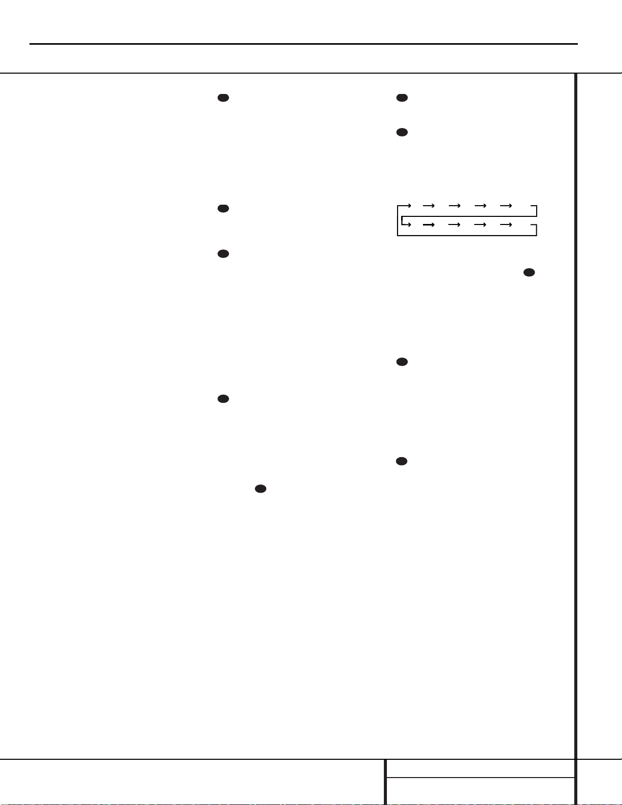
the following order:
Note that this button is also used to change
channels on your TV when the TV is selected
using the Video Remote Selectors .
When the AVR 7000 remote is being programmed for the codes of another device,this
button is also used in the “Auto Search” process.
(See page 34 for more information on programming the remote.)
Video Remote Selectors: Press one of
these buttons to use the remote to control the
functions of the device shown on the button. (For
more information on programming the remote to
operate these devices,see pages 34–35.)
NOTE: As any of these buttons is pressed, it
will briefly flash red to confirm your selection.
IR T ransmitter Window:Point this window towards the AVR 7000 when pressing buttons on the remote to make certain that infrared
commands are properly received.
Main Remote Control Functions
AVR7000 harman/kardon
19
28
29
30
31
34
32
33
90
min80min70min60min50min
30
40
min20min10min
min
OFF
34
34
35
Page 20
AVR7000 harman/kardon
20
harman/kardon
Service Bulletin
Service bulletin # H/K2000-03 Rev1 June 2000 Warranty labor rate: MINOR repair
To: All harman/kardon Service Centers
Models: AVR7000
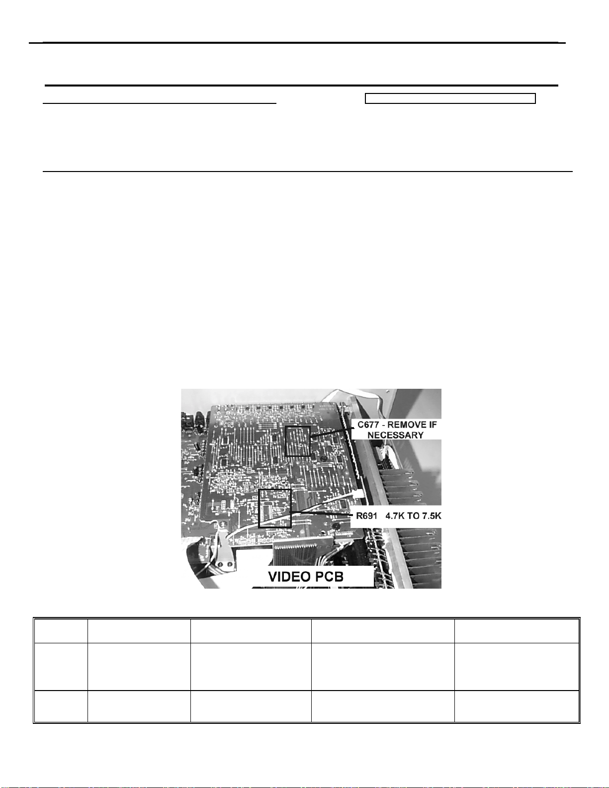
Subject: Video Signal, Color Shift
In the event you receive an AVR7000 receiver with the complaint “when the video signal is routed
through my AVR7000, there is a noticeable color shift with certain program material”, perform the
following modification:
1. CHANGE R691 ON THE VIDEO BOARD
CAUTION: THE AVR7000 CIRCUITS ARE ELE CTRO STATICALLY SENSITIVE.
TO PREVENT DAMAGE TO THE RECEIVER, FOLLOW PROPER STATIC CONTROL PROCEDURES.
a) Remove the top cover, (16 Black Phillips screws).
b) Locate the Video PC Board; it is the uppermost PCB and located at the rear corner of the receiver. See
illustration.
c) Remove
R691
and replace with 7.5kΩ 1/10W (h/k part#
260-7.5
).
2. REMOVE C677
If the part is present, locate and remove C677 SMD capacitor on the same (video) PCB. See illustration.
Test all major functions and confirm the color shift or original problem when the same program is played is
no longer occurring; replace top cover.
NOTE: In early AVR7000 schematics, R691 was erroneously mar ked as 47 kΩ.
Model
AVR7000
AVR7000
R691 Modification
Serial Number 120V
TH0003-01000
To
TH0003-05222
TH0003-05223
Or higher
C677 Removal
Serial Number 120V STATUS ACTION
TH0003-01000
To
TH0003-03213
TH0003-03214
Or higher
Color shift in TV picture when
using Video inputs and outputs.
Modified by factory NONE REQUIRED
Change R691
From 4.7kΩ to 7.5kΩ;
Remove C677 if necessary
harman/kardon Incorporated 250 Crossways Park Drive, Woodbury New York 11797 (516) 496-3400
Page 21
AVR7000 harman/kardon
21
harman/kardon Service Bulletin
Service bulletin # H/K2000-04 Rev1 February 2003
AVR500 MAJOR repair
To: All harman/kardon Service Centers AVR7000 MINOR repair
Models: AVR500/AVR7000
Subject: Noise in Logic 7 Mode
In the event you receive an AVR500 or AVR7000 receiver with the complaint “There is crackling, noise,
or distortion coming from my loudspeakers when my receiver is in the Logic 7 mode with certain
program material playing”, perform the following procedure:
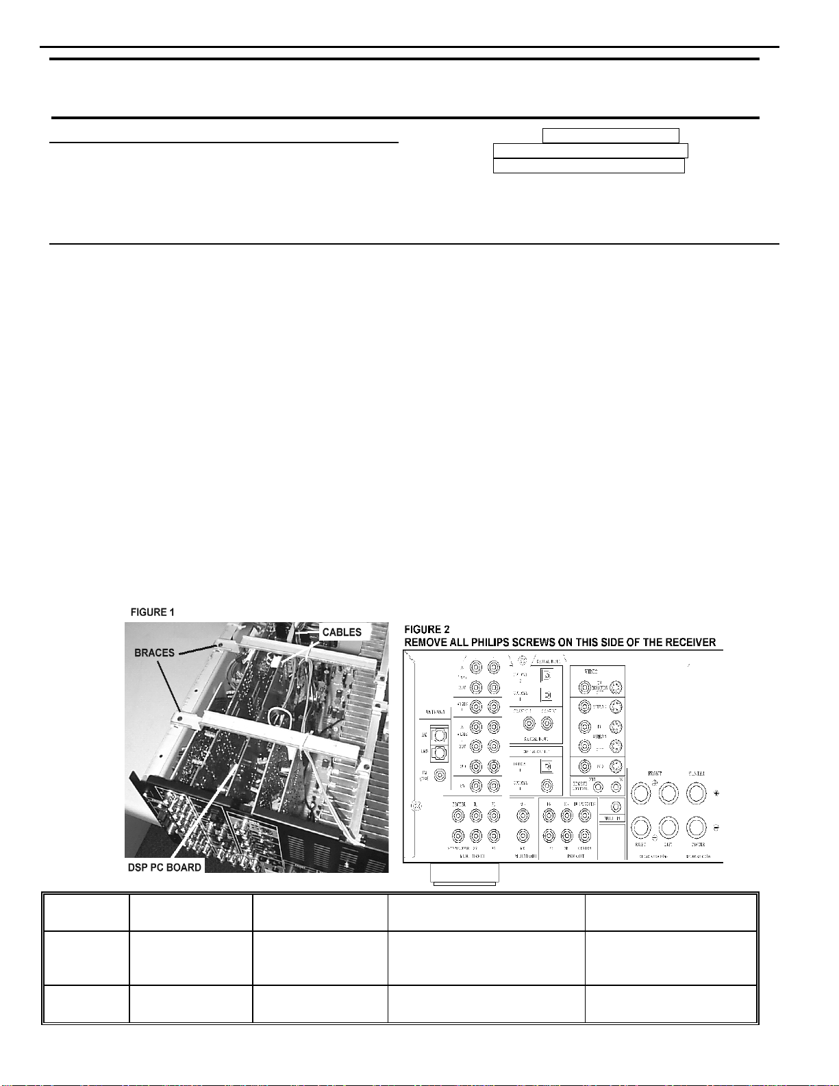
AVR500 ONLY: REMOVAL AND MODIFICATION OF THE DSP BOARD (replace IC709 TRAD ROM-0001)
WARNING: FOLLOW PROPER STATIC CONTROL PROCEDURES and use caution during the removal of the
DSP board, and during installation of new IC709 to prevent damage.
1) Remove the top cover, (14) Black Phillips screws at the sides and rear of the unit.
2) Locate the DSP PC Board; Figure 1. Remove the two metal braces at the top of the unit. If necessary, cut
the cable ties attached to the braces to move any wires away from the area.
3) Pull the white 22 conductor ribbon cable at the rear of the DSP PC Board straight out of its receptacle.
4) Unplug the white 5 conductor molex cable at the top of the DSP PC Board.
5) Remove the (33) plated Phillips screws on the left side of the rear backplate; see Figure 2. Do not remove
any additional screws on the right side. If using a power tool, use care and minimum effort to avoid
damaging the various plastic receptacles.
6) Remove all three black plastic plugs that cover the optical inputs at the rear of the DSP PC Board.
7) Pull on the left side of the rear backplate, away from the receiver chassis; you should be able to pull it away
enough to allow the DSP PC Board to be pulled straight up and out of the receiver.
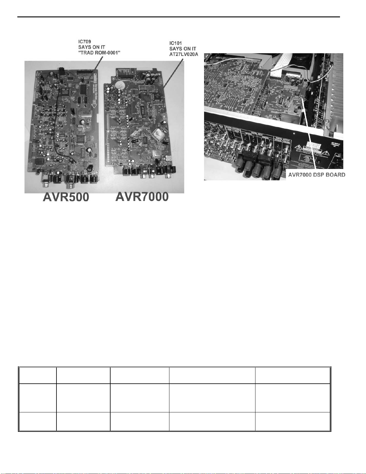
8) Unsolder IC709 TRAD ROM-0001 and replace with hk part# J21310030011. See illustration on following
page for location on PCB.
Warranty labor rate:
Model Serial Number
120V
AVR500
AVR500
TH0002-01000
To
TH0002-14977
TH0002-14978 or
higher
Serial Number
230V RDS
TH0006-01000
To
TH0006-05105
TH0006-05106 or
higher
STATUS
Noise in Logic 7 Mode
Modified by factory
TRAD ROM-0001
NONE REQUIRED
ACTION
Replace IC709
harman/kardon Incorporated 250 Crossways Park Drive, Woodbury New York 11797 (516) 496-3400
Page 22
AVR7000 harman/kardon
22
Location of IC upgrade for the AVR500/AVR7000:
9) Replace DSP PC Board back into its (3) receptacle plugs atop the MAIN PCB.
10) Replace all screws, braces, and any cable ties that were cut during disassembly. Before tightening the
screws, make sure all PCB’s and their RCA jacks are firmly seated in their respective holes in the rear
backplate. If using a power tool, use care and minimum effort to avoid damaging the various plastic
receptacles.
11) Plug both the 22 conductor ribbon cable and the 5 conductor molex cable back into their receptacles.
12) Replace the top cover and optical plugs.
13) Test unit by powering up the receiver and playing a music source in the Logic 7 mode.
AVR7000 ONLY: MODIFICATION OF THE DSP BOARD (replace IC101 AT27LV020A)
WARNING: FOLLOW PROPER STATIC CONTROL PROCEDURES and use caution during the installation of
new IC101 to prevent damage.
1) Remove the top cover, (16) Black Phillips screws at the sides and rear of the unit.
2) Locate the DSP PC Board and IC101 with the illustrations above.
3) Unsolder IC101 AT27LV020A and replace with hk part# 55172540AVR7000. See illustration above for
location on PCB.
4) Replace top cover and all Phillips screws.
5) Test unit by powering up the receiver and playing a music source in the Logic 7 mode.
Model Serial Number
120V
AVR7000
AVR7000
TH0003-01000
To
TH0003-05222
TH0003-05223
Or higher
Serial Number
230V RDS
Modified by factory
Modified by factory
STATUS
Noise in Logic 7 Mode
Modified by factory
NONE REQUIRED
ACTION
Replace IC101
AT27LV020A
harman/kardon Incorporated 250 Crossways Park Drive, Woodbury New York 11797 (516) 496-3400
Page 23

AVR7000 harman/kardon
23
harman/kardon
Service Bulletin
Service bulletin # H/K2000-06 April 2000 Warranty labor rate: MINOR repair
To: All harman/kardon Service Centers
Models: AVR7000
Subject: Switched AC Accessory Outlet Dead
The Switched AC Accessory Outlets on the AVR7000 are used to power up any low-wattage
device when the AVR7000 is switched on with the System Power Control. Ordinarily this means
CD players, DVD players, Tape Decks, etc. or any device not exceeding 100 watts per outlet.
These accessory outlets are not intended to be used with higher-power devices such as television
sets, power amplifiers or powered subwoofers.
However, under some circumstances, even the use of a recommended device connected to the
AVR7000’s Switched AC Accessory Outlets may briefly exceed the current rating of the internal
1A AC accessory fuse, and blow the fuse.
In the event you receive an AVR7000 with the complaint “The switched AC accessory outlet
at the rear of my receiver is dead”, perform the following procedure:
1) Remove the top cover, (16 Black Phillips screws).
2) Locate F451, a 1A GMC (5 x 20mm) fuse at the rear corner of the unit, where the AC power
cord enters the rear cover. Remove it and replace with a 3.15A GMC (5 x 20mm)
Slo-Blo fuse, h/k part# 5508302735 . Original fuse can be extracted with a pair of long-nosed
pliers.
3) Replace the top cover.
4) Test the Switched AC Accessory Outlets by connecting a low power device, such as a CD
player, DVD player, or Tape Deck and assure the unit powers up normally when the AVR7000
System Power Control is switched on.
Model Serial Number
120V
TH0003-01000
AVR7000
To
TH0003-07963
Switched AC Accessory
STATUS ACTION
Change F451
Outlet Dead
From 1A to 3. 15A
AVR7000
TH0003-07964
Or higher
Modified by factory NONE REQUIRED
Page 24

AVR7000 harman/kardon
24
harman/kardon Service Bulletin
Service bulletin # H/K2002-06 October 2002 Warranty labor rate: MINOR repair
To: All harman/kardon Service Centers
Model: AVR7000
Subject: Low or No Output from Subwoofer Output Jack
In the event you receive an AVR7000 receiver with the complaint “There is little or no output from the
subwoofer output jack, to drive my powered subwoofer”, follow the instructions below:
1) Check to make sure the AVR7000 is configured correctly for Subwoofer Output:
a) You will need a Video display (monitor or TV set, composite connection) connected to one of the
“Monitor Out” jacks at the rear of the AVR7000, to view the on-screen menu for these steps.
b) You will need a source, in this case a CD player, connected with RCA cables (Analog) to the CD input
jacks at the rear of the AVR7000. A Compact Disc with ample bass information should be inserted in
the CD player.
c) Connect a powered subwoofer to the Subwoofer Output Jack on the AVR7000.
d) With the AVR7000 turned ON, select input: Press the CD button on the remote control. The words
CD Player should appear in the display panel, as well as being indicated in the front panel Input
Indicators, by the green LED next to “CD” on the right-hand side of the panel.
e) Select Dolby Pro Logic: Press the OSD button on the remote control to bring up the AUDIO SET UP
menu. Press the
button so that the SURROUND SETUP menu is on-screen. Since the factory default for all inputs is
Stereo, the words SURR OFF should initially appear. To change, press the
PRO LOGIC appears. A green LED will also light next to the DOLBY PRO LOGIC in the Surround
Mode Indicators on the left side of the front panel.
f) Press the
be back to the AUDIO SET UP menu. Move the cursor with the
SETUP line, then press the Set button to bring up the SPEAKER SETUP menu. For the first three
lines on the menu, the word SMALL should appear on the right side. If the word LARGE appears in
any of the lines, press the
then press the
be sent only to the subwoofer output.)
g) Make sure for the line SUBWOOFER, the word YES appears. If NO is there, press the
the remote until it’s next to the SUBWOOFER line; press the
h) Press the OSD button on the remote control again, if desired, to turn off the On-Screen Display.
i) Turn on the CD player and play the CD, with the AVR7000 volume at a reasonable level, with the
powered subwoofer turned ON, with its volume control also turned up to a reasonable level. Has this
solved the problem ? If NO, proceed to step #2.
6 button until the cursor is next to RETURN TO MENU; press the Set button. You should
6 button until the cursor is next to the SURROUND SETUP menu. Press the Set
4 buttons until DOLBY
6 button until it’s on the SPEAKER
6 button on the remote until it’s next to any line you need to change, and
4button until SMALL appears. (When SMALL is selected, low frequency sounds will
6 button on
4button until the word YES appears.
1
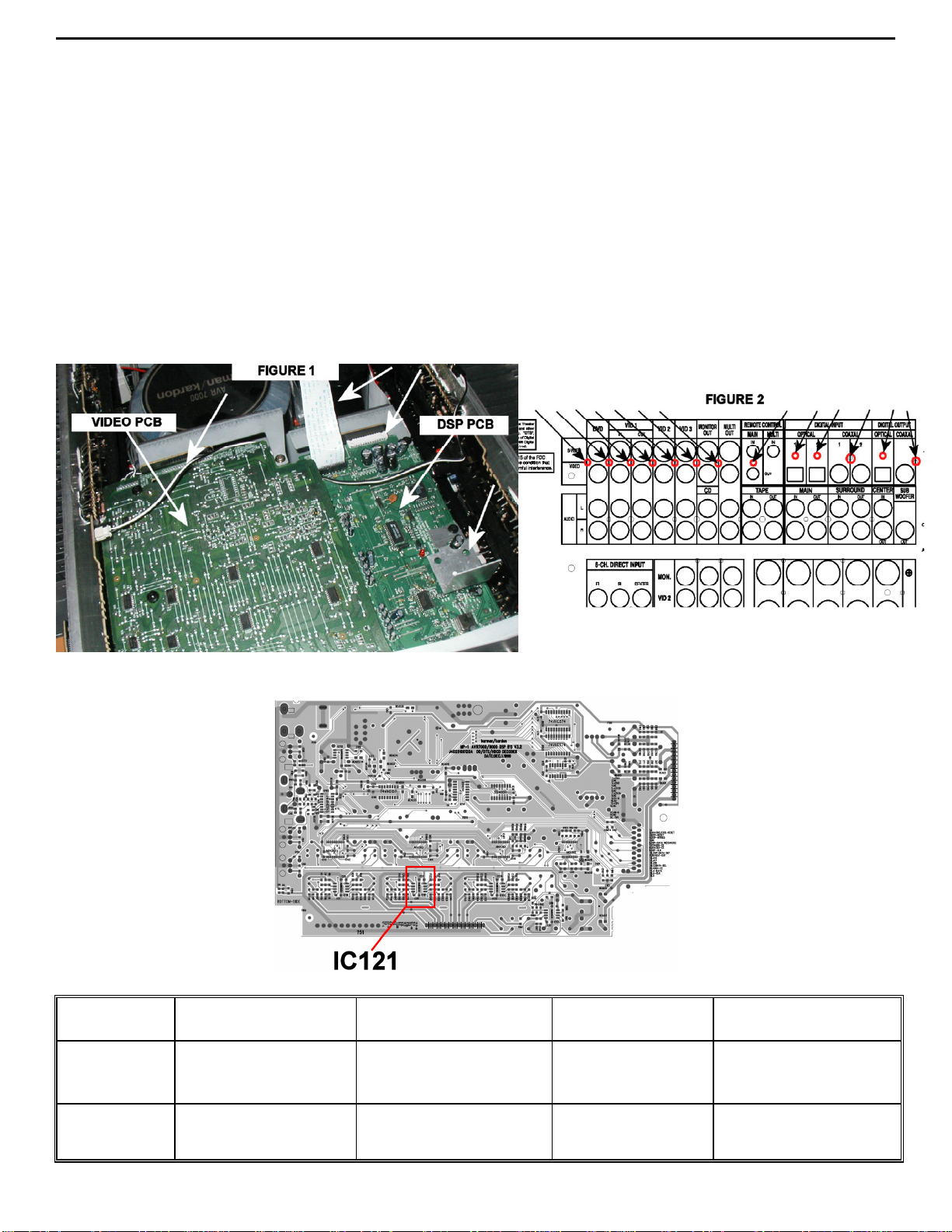
2) Check for sufficient solder on pin 5 of IC121. IC121 is an Op Amp (NJM5532M) on the DSP PCB.
CAUTION: THE AVR7000 CIRCUITS ARE ELECTROSTATICALLY SENSITIVE.
TO PREVENT DAMAGE TO THE RECEIVER, FOLLOW PROPER STATIC CONTROL PROCEDURES.
a) Remove the top cover, (16 Black Phillips screws). You should be working at the rear of the receiver.
b) Unplug the white ribbon cable from the rear of the DSP PCB (see figure 1)
c) Remove (13) black screws from the rear of the AVR7000 holding the Video and DSP PCB’s (see figure
2).
d) On the top of the Video PCB, remove the (3) remaining screws (2 black and 1 plated) holding the Video
PCB to the chassis; remove the single black screw holding the bracket support to the DSP PCB.
e) Unplug the small, white, 2-pin molex connector snaking across the top of the Video PCB.
f) Loosen (do not remove) the 2 remaining bracket support screws at the bottom of the bracket, at the
bottom of the AVR7000 chassis; you should now be able to push the bracket back far enough to be able
to remove both the Video and DSP PCB’s when necessary.
Page 25
AVR7000 harman/kardon
25
g) Disengage the Video PCB from its rear connector (CP601) by pushing back on the rear PCB; lift the
Video PCB up and out of the unit. It should still have an amber-colored 8 pin connector attached. Set the
PCB aside and out of the way.
h) Remove the (2) remaining screws (1 plated, 1 black) holding the DSP PCB to the chassis. The black
screw will loosen a small aluminum heatsink (for IC100); remove it.
i) Disengage the DSP PCB from its rear connector (CP401) by pushing back on the rear PCB; lift the DSP
PCB up and out of the unit; turn it upside down. It should still have an amber-colored 15 pin connector
attached.
j) Locate IC121 (see figure 3) and resolder if needed.
k) Replace parts in reverse order; remember to re-tighten the bottom bracket screws and replace the
heatsink. CAUTION: At the rear screws, if using a power tool, use care and minimum effort to avoid
damaging the various plastic receptacles.
l) Test the unit by following steps (a – i) in section 1.
2
MODEL
AVR7000
AVR7000
SERIAL NUMBER
120V
TH0003-01000
to
TH0003-12085
TH0003-12086
and above
FIGURE 3
SERIAL NUMBER
230V
TH0012-01000
to
TH0012-12386
TH0012-12387
and above
STATUS ACTION
IC121 may need re-
soldering
Check for sufficient solder
NONE REQUIRED
on pin 5 of IC121
Page 26

AVR7000 harman/kardon
26
harman/kardon TECH TIPS
Troubleshooting tips and solutions to common service problems
For models: AVR7000 TIP# HKTT2000-01
Complaint:
The Remote Control has stopped working for the AVR7000.
First Check:
1. Make sure the batteries in the remote are installed correctly. (Plus and minus to correct terminals)
2. Make sure the area between the remote control and receiver is not blocked by some object, and the
distance is no more than 15 feet at an angle no greater than 30 degrees from the front of the receiver.
3. Make sure strong lighting is not directed towards the IR sensor of the receiver.
4. Press each button on the remote and verify proper operation.
If these steps are taken and remote control still does not function properly −
Probable Cause:
Factory-supplied batteries.
Solution:
1. Remove the batteries from the remote. Leave batteries out of the remote for a minimum of three minutes.
This ensures the internal capacitors discharge, allowing the CPU in the remote to re-boot.
2. Reinstall new alkaline batteries (major brand recommended).
3. Press the AVR button and the Mute button at the same time until the red light illuminates under AVR.
4. Enter the numbers 0-0-1 on the numerical keypad.
5. Press the AVR button again.
Test the remote control. It should be functioning properly once this is completed.
Page 27

AVR7000 harman/kardon
27
harman/kardon TECH TIPS
Troubleshooting tips and solutions to common service problems
For models:
AVR7000/7200/7300/8000
AVR100/200/300/500
AVR110/210/310/510
AVR120/220/320/520
AVR125/225/325/525
AVR130/230/330/430/630
AVR135/235/335/435/635
AVR10
DPR1001
DPR1005
DPR2005
HK3370/3470/3375/3475
HK3250
Subject: Backup Memory on AVR/DPR/HK series receivers
In the event of the complaint: “the receiver is losing its memory (any programmed system settings)
when the unit is turned off, or after the unit is unplugged (briefly*)”:
Check and replace:
Model Designator Location Description Part number
AVR10
AVR7000 C730 Front PCB 0.047 Farad 5.5v capacitor
AVR7200 C106 Front PCB 0.047 Farad 5.5v capacitor # P10790-ND
AVR7300 C657 DSP PCB 0.047 Farad 5.5v capacitor # H01-CEZXA0479MN-5
AVR8000 C726 Front PCB 0.047 Farad 5.5v capacitor
AVR100/200 C412 Front PCB 0.047 Farad 5.5v capacitor # CEGT-B473J-0J0
AVR300 C906 Front PCB 0.1Farad 5.5v capacitor
AVR500 C906 Front PCB 0.1Farad 5.5v capacitor
AVR110/210/310/510
AVR120/220/320/520
AVR125/225 C734,C885 Front PCB two 0.1F capacitors in parallel # BCESOHD104
AVR325/525 C106 Front PCB 0.047 Farad 5.5v capacitor # P10790-ND
AVR130/230/330 BAT1 Front PCB 3.6v Battery # HABGP40BVH3A3H
AVR135/235/335 BAT1 Front PCB 3.6v Battery # HGP15BNH3A3H
AVR430/630 C657 DSP PCB 0.047 Farad 5.5v capacitor # CEZXA0479MN-5
AVR435/635 C557 DSP PCB 0.047 Farad 5.5v capacitor # H03-CEZXA0479MN-0
DPR1001 BC601 Main PCB 0.1Farad 5.5v capacitor # CEGT-B104J-0J0
DPR1005/2005 C437
HK3370/3470 C301 Front PCB 0.1Farad 5.5v capacitor # CEGT-B104J-0J0
HK3375/3475 C301 Front PCB 0.1Farad 5.5v capacitor # CEGT-B104J-0J0
HK3250
* After approximately two weeks of being disconnected from A C supply, even a normally functioning receiver m ay
lose any program med settings and switch t o default settings. (Four weeks f or the DPR1005 & 2005)
C712
D709
C216 Front PCB 0.047 Farad 5.5v capacitor # P10790-ND
C712
D709
Front PCB
Processor
PCB
Front PCB
0.047 Farad 5.5v capacitor
and 1N4148 diode
0.047 Farad 5.5v capacitor # CEZXA0479MN-5
0.047 Farad 5.5v capacitor
and 1N4148 diode
TIP# HKTT2003-01 Rev5
#3439247315
#2058322101
# P10790-ND or
# J3432147324X
# 55230310NR or
# P10790-ND
# J4433210421X
or # P10791-ND
# J4433210421X
or # P10791-ND
#3439247315
#2058322101
Page 28
AVR7000 harman/kardon
28
AVR7000 IDLE CURRENT ADJUSTMENT
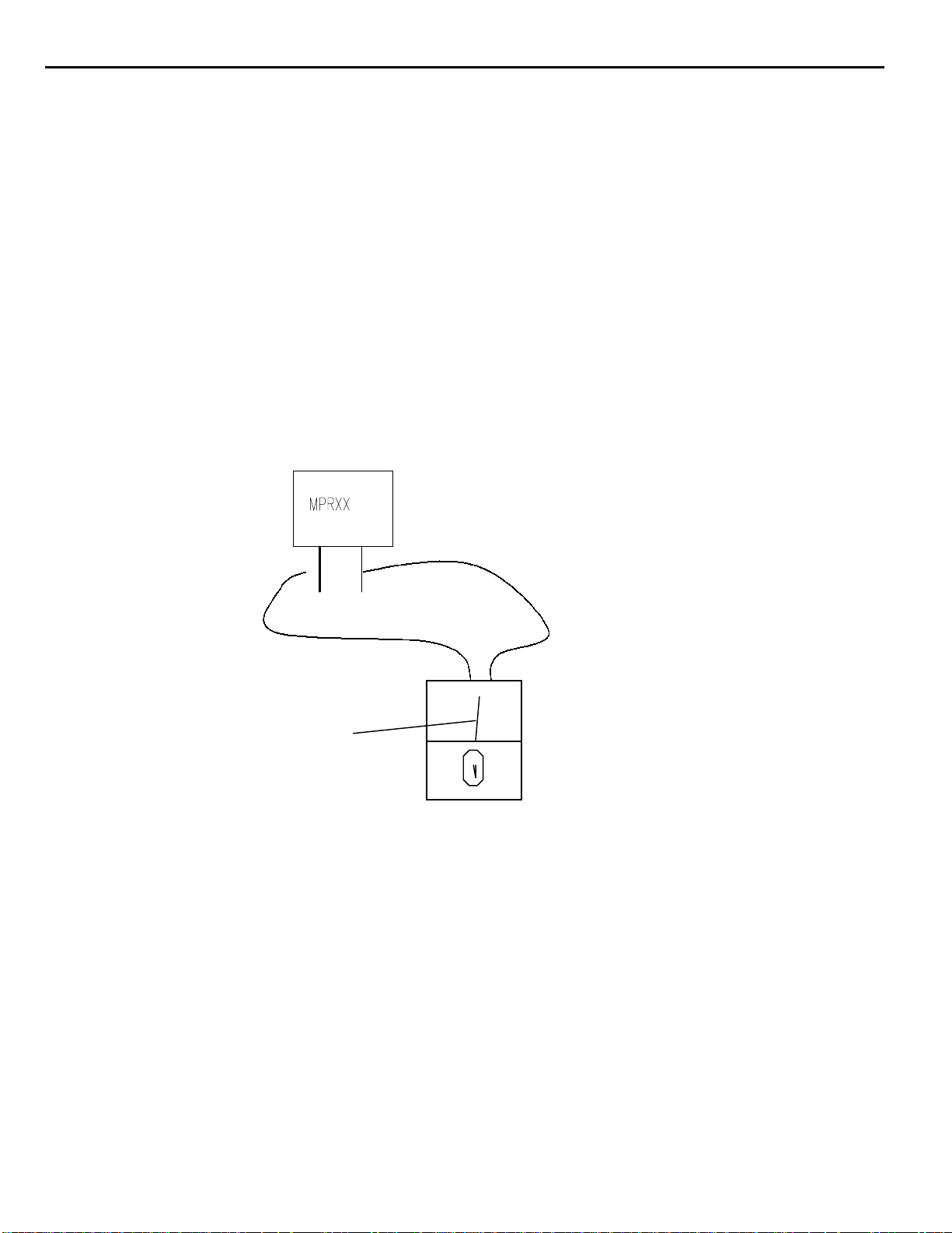
1) 2-CH AMP and 3-CH AMP sections should be adjusted when they are intact on the Heat-sink
2) Initial warm-up and test condition: 1Khz - Signal input, SPKR-OUT(8ohm load), 5CH All driven
3) Warm up 3 minutes in step 2, then remove input signal
4) Emitter resistors - connections across MPR901,904, MPR907,910,913 as follows:
adjust voltage to 26mV ± 5mV connected across opposite ends of resistor leads.
5) Potentimeters to adjust are as follows:
a) Front right channel (MPR901) - VR901
b) Front left channel (MPR907) - VL901
c) Center channel (MPR910) - VC901
d) Rear left channel (MPR913) - VSL901
e) Rear right channel (MPR904) - VSR901
26mV +/- 5mV
Page 29

r
v
a
n
s
%
TEST
i
•999
d
•999
a
•98
•98
•98
s
AVR7000 harman/kardon
29
AVR700 TUNER ALIGNMENT
• Europe Mono 40kHz Stereo 67.5kH
1.Electrical specificat
NO.
1-1
1-2
1-3
1-4
1-5
Local OSC
Frequency cover
Standard supply
FM Antenna input
AM Loop Antenna
ITEMS
• America Mono 75kHz Stereo 40kHz
M W F M
Above the receiving Frequency
•522 ~ 1620kHz
•520 ~ 1720kHz
2.Electrical Characteristics.
NO
TEST ITEMS
AF Output L
FM
Auto Stop Sens.
Stereo Sep
CONDITIO
47• Lo
1kHz
T.P.
dBu
.
0
.
0
.
0
SPECIFICATION
•87.5 ~ 108.0MHz
•87.5 ~ 107.9MHz
15.0 (+/-1.5V)
75 ohm
18uH ( 50 ohm )
OD.
.L.
60
--
60
cificat
Hz,
•40
500±100 mV
•75
•40
33.2 ±6
•75
40 min
UNIT
djustme
n Adju
dBf SVR2
dB
SVR3
AF Output L
MW
Auto Stop Sens.
7• Loa
3.Adjustment Points
•100
•100
74
30 165±50
--
30 800±6
mV
uV/m
n Adju
SVR1
Page 30
i
k
a
o
I
e
r
e
d
s
d
%
M
t
s
AVR7000 harman/kardon
30
AVR700 TUNER ALIGNMENT (con't)
Europe Mono 40kHz Stereo 67.5kHz Pilot 7
1.Electrical spec
NO.
1-1
1-2
1-3
1-4
1-5
Local OSC
Frequency cover r
Standard supply v
FM Antenna input
AM Loop Antenna
ITEMS
America Mono 75kHz Stereo 40kHz Pilot 7.5
SPECIFICATION
M W F M
Above the receiving Frequency
•522 ~ 1620kHz
•520 ~ 1720kHz
15.0 (+/-1.5V)
75 ohm
18uH ( 50 ohm )
•87.5 ~ 108.0MHz
•87.5 ~ 107.9MHz
2.Electrical Characteristics.
NO
TEST ITEMS
AF Output L
FM
Auto Stop Sens.
Stereo Sepa
AF Output L
MW
Auto Stop Sens.
TEST
CONDITION
47• Loa
1kHz
7• Loa
•98.0
•98.1
•98.0
•98.1
•98.0
•98.1
•999
•1000
•999
•1000
OD.T.L.
ecificatiT.P.
dBu
Hz,
•40
60
•75
•40
--
•75
60
74
-- uV/m
500±100 mV
33.2 ±6
40 min
30 165±50
30 800±6
UNIT
dBf SVR2
dB
mV
djustmen
on Adju
SVR3
on Adju
SVR1
Page 31

AVR7000 harman/kardon
31
AVR700 TUNER ALIGNMENT (con't)
3.Adjustment Points
Page 32

TROUBLESHOOTING GUIDE
Troubleshooting Guide
SYMPTOM CAUSE SOLUTION
Unit does not function when Main • No AC Power • Make certain AC power cord is plugged into
Power Switch is pushed a live outlet
• Check to see if outlet is switch-controlled
Display lights,but no sound • Intermittent input connections • Make certain that all input and speaker connections
or picture • Mute is on are secure
• Volume control is down • Press Mute button
• Turn up volume control
Unit turns on, but Front-Panel • Display brightness is turned off • Follow the instructions in the Display Brightness section
Display does not light up on page 31 so that the display is set to VFD FULL
No sound from any speaker; • Amplifier is in protection mode • Check speaker wire connections for shorts at receiver and
Light around power switch is red due to possible short speaker ends
• Amplifier is in protection mode • Contact your local Harman Kardon service depot
due to internal problems
No sound from surround or • Incorrect surround mode • Select a mode other than Stereo
center speakers • Input is monaural • There is no surround information from mono sources
• Incorrect configuration • Check speaker mode configuratioin
• Stereo or Mono program material • The surround decoder may not create center or rear channel
information from nonencoded programs
Unit does not respond to • Weak batteries in remote • Change remote batteries
remote commands • Wrong device selected • Press the AVR selector
• Remote sensor is obscured • Make certain front panel sensor is visible to remote
or connect remote sensor
Intermittent buzzing in tuner • Local interference • Move unit or antenna away from computers,fluorescent
lights,motors or other electrical appliances
Letters flash in the Channel Indicator • Digital audio feed paused • Resume play for DVD
Display and Digital Audio stops • Check that Digital Input is selected
HDCD encoded disc does not trigger • Surround mode in use • Select “Surround Off”mode
HDCD indicator • Analog feed in use • Connect and select digital connection to CD player
Processor Reset
In the rare case where the unit’s operation or
the displays seem abnormal, the cause may
involve the erratic operation of the system’s
memory or microprocessor.
To correct this problem,first unplug the unit
from the AC wall outlet and wait at least three
minutes. After the pause,reconnect the AC
power cord and check the unit’s operation.If
the system still malfunctions,a system reset
may clear the problem.
To clear the AVR 7000’s entire system memory
including tuner presets,output level settings,
delay times and speaker configuration data,
first put the unit in Standby by pressing the
System Power Control button 2. Next,
press and hold the Tone Mode 6 and the
FM Mode Selector @ buttons for three
seconds.
The unit will turn on automatically and display
the RESET message in the Main
Information Display W. Note that once you
have cleared the memory in this manner, it is
necessary to re-establish all system configuration
settings and tuner presets.
NOTE:Resetting the processor will erase any
configuration settings you have made for
speakers,output levels, surround modes, digital
input assignments as well as the tuner presets.
After a reset the unit will be returned to the
factory presets,and all settings for these items
must be reentered.
If the system is still operating incorrectly,there
may have been an electronic discharge or
severe AC line interference that has corrupted
the memory or microprocessor.
If these steps do not solve the problem, consult
an authorized Harman Kardon service depot.
AVR7000 harman/kardon
32
Page 33

AVR7000 harman/kardon
33
Page 34

AVR7000 harman/ kardon
34
Page 35

35
Page 36

AVR7000 harman/kardon
36
Page 37

AVR7000 harman/kardon
37
Page 38

AVR7000 harman/kardon
38
Page 39

AVR7000 harman/kardon
39
Page 40

AVR7000 harman/kardon
40
Page 41

AVR7000 harman/kardon
41
Page 42

AVR7000 harman/kardon
42
Page 43

43
Page 44

AVR7000 harman/kardon
44
Page 45

AVR7000 harman/kardon
45
Page 46

AVR7000 harman/kardon
46
Page 47

AVR7000 harman/kardon
47
Page 48

AVR7000 harman/kardon
48
Page 49

AVR7000 harman/kardon
49
Page 50

AVR7000 harman/kardon
50
Page 51

AVR7000 harman/kardon
51
Page 52

AVR7000 harman/kardon
52
AVR7000 MECHANICAL PARTS LIST
--JE99005307EA MNBD ASM 7000RDS 1
JE99005307UA MNBD ASM AVR7000 1
JE99005507EA FRBD ASM 7000RDS 1
JE99005507UA FRBD ASM AVR7000 1
JE99005907UA PREBD ASM AVR7000 1
JE99006307EA VIDBD ASM 7000RDS 1
JE99006307UA VIDBD ASM AVR7000 1
JE99006707UA DSPBD ASM AVR7000 1
JE99007107EA SUPBD ASM 7000RDS 1
JE99007107UA SUPBD ASM AVR7000 1
JE99007307UA 2CH AMPBD ASM 7000 1
JE99007507UA 3CH AMPBD ASM 7000 1
JAVR7000XXXX EXPLODED VIEW
B2822110014X TRABASFORM BOTTOM
T2822110014X TRABASFORM TOP
JHKEAVRC0001 AVR7000 SPEC
JHKE450001 PEC RELIA TEST
J6171140010X WIRE TIE NYLON6 1
J4099100070X TUMER MODULE US 1
J4099100090X TUNER MODULE RDS 1
J5541003012X CUSHION RUBBER 1
J60400000001 PANEL FRONT AL 1
J60400000002 PANEL FRONT AL 1
J60550003000 BADGE HARMAN/KARDO 1
J65040000000 KNOB MAIN HIPS 1
J85000007000 BODY FRONT HIPS 1
J85100009000 KNOB TONE HIPS 1
J85200050000 BUTTON 7KEY HIPS 1
J85200051000 BUTTON 3KEY HIPS 1
J85200053000 BUTTON 5KEY HIPS 1
J85300011000 WINDOW DISPLAY 1
J85400020000 INDICATOR VIDEO 4 1
J85400021000 ENDCAP LEFT HIPS 1
J85400022000 ENDCAP RIGHT HIPS 1
J85500004000 FILTER DISPLAY 1
J85810011000 GUIDE BUTTON 5KEY 1
J85940002000 DIFFUSER PLATE 1
J60300012000 BKT SW POWER 1
J85200049000 BUTTON POWER HIPS 1
J85810010000 GUIDE POWER SW 1
J85200052000 BUTTON STANDBY 1
J85400019000 INDICATOR STANDBY 1
J60300002000 BRACKET HEADPHONE 1
J60100000001 COVER TOP 1
J60100001100 COVER TOP 1
J60000004001 CH MAIN 1
J60020000301 CH FRONT 1
J85900501000 FOOT-ASS'Y 1
J85900503000 FOOT-RUBBER 1
J5222000910X BKT HEATSINK SECIT 1
J60500003000 HEATSINK POWER 3CH 1
J60500004000 HEATSINK POWER 2CH 1
J5541001010X WASHER SPRING 1
20372510XX WASHER 3.5MM 9.0MM 1
J5541001020X WASHER FLAT 1
J2822110014X*POWER TRANS 120/60 1
J2822410014X*POWER TRANS 230/50 1
J43730100200*CORD AC POWER 1
J43731100200*CORD AC POWER RDS 1
J43732100200*CORD AC POWER SG 1
J60110001000 PANEL REAR SECC 1
J60110001001 PANEL REAR 7000RDS 1
J60110001002 PANEL REAR 7000SG 1
J5636140010X SCREW 1
J5636140040X SCREW 1
J81000300810 SCREW BM3*6Y 1
J5636140150X SCREW 1
JAVR7000SCRW SCREW 3X12PT 1
J5636140080X SCREW A124008000 1
J5636140270X SCREW 1
J90720301080 SCREW 3*10 TEETH T 1
J5636130080X SCREW 1
J5541001030X WASHER SPRING 1
J5541001040X WASHERPLAT INNER 1
20290110XX LUBRICANT HYCHEM/T KG
J85810009000 FL GUIDE HIPS 94HB 1
J85940003000 REFRACTOR 3 1
J85940001000 REFRACTOR-1 1
J97100502000 LABEL-DATE 1
20181850XX CABLE-FIX WIRE-TIE 1
J70800000100 STUD 34 1
J70800000200 STUD 54 1
J70800000300 STUD 55 1
J70800000400 STUD 62.6 1
J60300013000 BKT SUPPORT SECC 1
J60300037000 BKT TOP 1
J60300015000 BKT PREAMP PCB 1
J60300046000 BKT SIDE SECC1.0T 1
J81000400810 SCREW D020400800 1
J97100501010 LABEL-SERIAL 7000S 1
J9710050900X LABEL-SERIAL NO PA 1
J97100509010 LABEL-SERIAL 1
J97100503000 LABEL RISK 1
20932870XX AC PRI LABEL QC CH 1
J94100002000 SHIELD FORM 71TSN 1
J94100003000 SHIELD FORM 71SN 1
J65540000500 PLLATE SPRING 1
J2632100025X EMI-CORD 1
J2632400015X FERRITE CORE CLAMP 1
J2632400025X FERRITE CORE CLAMP 1
J2632400035X CORD CLAMP 50W-1 1
J7001SYLINDR*TRANSFORMER CYLIND 1
J2831410014X*TRANS CHOKE EI 1
J60600013000 BKT SHIELD EMI SEC 1
J60600016000 SHIELD PLATE LARGE 1
J60600015000 SHIELD PLATE SMALL 1
J60600017000 SHIELD PLATE DSP 1
J60600018000 SHIELD PREAMP 1
J5131000007X KNOB CORK 1
-------------------------------------------------------------------------------------------- 0110 J85000007000 BODY FRONT HIPS F4799
13 01101 M85000007000 BODY FRONT HIPS RA 1.00000 M F5299 02 1
-------------------------------------------------------------------------------------------- 0120 J85100009000 KNOB TONE HIPS F4799
Page 53

AVR7000 harman/kardon
53
13 01201 M85100009000 KNOB TONE HIPS RAW 1.00000 M F5299 02 1
-------------------------------------------------------------------------------------------- 0240 J85200049000 BUTTON POWER HIPS F4799
13 02401 M85200049000 BUTTON POWER HIPS 1.00000 M F5299 02 1
02406 20289980XX DILUTION IPI-783 3 LI .00001 B F4799 1
---------------------------------------------------------------------------------------------
-- 0130 J85200050000 BUTTON 7KEY HIPS F4799
13 01301 N85200050000 BUTTON 7KEY HIPS R 1.00000 M F5299 02 1
---------------------------------------------------------------------------------------------
-- 0140 J85200051000 BUTTON 3KEY HIPS F4799
13 01401 M85200051000 BUTTON 3KEY HIPS R 1.00000 M F5299 02 1
---------------------------------------------------------------------------------------------
-- 0260 J85200052000 BUTTON STANDBY F4799
13 02601 M85200052000 BUTTON STANDBY HIP 1.00000 M F5299 02 1
---------------------------------------------------------------------------------------------
-- 0150 J85200053000 BUTTON 5KEY HIPS F4799
13 01501 M85200050300 BUTTON 5KEY HIPS R 1.00000 M F5299 02 1
-------------------------------------------------------------------------------------------- 0270 J85400019000 INDICATOR STANDBY F4799
02701 55022170XX GRANULES SAN TYRIL KG .00200 B F5299 02 1
---------------------------------------------------------------------------------------------
-- 0170 J85400020000 INDICATOR VIDEO 4 F4799
-------------------------------------------------------------------------------------------- 01701 55006550XX GRANULES SAN SAN T KG .00100 B F5299 02 1
---------------------------------------------------------------------------------------------
-- 0180 J85400021000 ENDCAP LEFT HIPS F4799
13 01801 M85400021000 ENDCAP LEFT HIPS R 1.00000 M F5299 02 1
---------------------------------------------------------------------------------------------
-- 0190 J85400022000 ENDCAP RIGHT HIPS F4799
13 01901 M85400022000 ENDCAP RIGHT HIPS 1.00000 M F0200 03 1
---------------------------------------------------------------------------------------------
-- 0610 J85810009000 FL GUIDE HIPS 94HB F4799
06101 20290570XX GRANULES PS ATOCHE KG .00940 B F5299 02 1
---------------------------------------------------------------------------------------------
-- 0250 J85810010000 GUIDE POWER SW F4799
02501 20290570XX GRANULES PS ATOCHE KG .00100 B F4799 1
---------------------------------------------------------------------------------------------
-- 0210 J85810011000 GUIDE BUTTON 5KEY F4799
13 02101 M85810011000 BUTTON 5KEY RAW 1.00000 M F5299 02 1
---------------------------------------------------------------------------------------------
-- 0320 J85900501000 FOOT-ASS'Y F4799
13 03201 J528003020M FOOT-MOLD RAW 1.00000 M F4799 01 1
03202 AP82447619AL STAMPING FOIL FT .00500 B F4799 1
---------------------------------------------------------------------------------------------
-- 0630 J85940001000 REFRACTOR-1 F5099 01
06301 55022780XX GRANULES ABS TORAY KG .00300 B F2600 04 1
---------------------------------------------------------------------------------------------
-- 0620 J85940003000 REFRACTOR 3 F4799
06201 55022780XX GRANULES ABS TORAY KG .00250 B F2600 04 1
Page 54

AVR7000 harman/kardon
54
------------------------- 0320 J5283003020M FOOT-MOLD RAW F5299 01
03201 55010080XX GRANULES ABS TORAY KG .01396 B F5299 01 1
03202 55015950XX GRANULES PIGMENT K KG .00014 B F5299 01 1
---------------------------------------------------------------------------------------------
-- 0110 M85000007000 BODY FRONT HIPS RA F5299 01
01101 20290570XX GRANULES PS ATOCHE KG .32000 B F5299 01 1
---------------------------------------------------------------------------------------------
-- 0120 M85100009000 KNOB TONE HIPS RAW F5299 01
01201 20290570XX GRANULES PS ATOCHE KG .01800 B F5299 01 1
-------------------------------------------------------------------------------------------- 0240 M85200049000 BUTTON POWER HIPS F5299 01
02401 20290570XX GRANULES PS ATOCHE KG .00100 B F5299 01 1
-------------------------------------------------------------------------------------------- 0130 M85200050000 BUTTON 7KEY HIPS R F5299 01
C2 01301 JAVRC0000001 SHALLOW GREEN RAW KG .02900 M F2600 02 1
-------------------------------------------------------------------------------------------- 0140 M85200051000 BUTTON 3KEY HIPS R F5299 01
C2 01401 JAVRC0000001 SHALLOW GREEN RAW KG .00800 M F2600 02 1
-------------------------------------------------------------------------------------------- 0260 M85200052000 BUTTON STANDBY HIP F5299 01
02601 20290570XX GRANULES PS ATOCHE KG .00220 B F5299 01 1
-------------------------------------------------------------------------------------------- 0150 M85200053000 BUTTON 5KEY RAW F5299 01
01501 JAVRC0000001 SHALLOW GREEN RAW KG .00800 B F5299 01 1
-------------------------------------------------------------------------------------------- 0180 M85400021000 ENDCAP LEFT HIPS R F5299 01
01801 20290570XX GRANULES PS ATOCHE KG .01200 B F5299 01 1
-------------------------------------------------------------------------------------------- 0190 M85400022000 ENDCAP RIGHT HIPS F5299 01
01901 20290570XX GRANULES PS ATOCHE KG .01200 B F5299 01 1
-------------------------------------------------------------------------------------------- 0210 M85810011000 BUTTON 5KEY RAW F5299 01
02101 20290570XX GRANULES PS ATOCHE KG .00320 B F5299 01 1
PACKAGING
J4482220011X AM ANTENNAL LOOP 1
J4481250011X FM ANT 75 WIRE ANT 1
J4481250021X ANT FM 75OHM WIRE 1
J54000000100 ASS'Y REMOCON 1
J54000000110 ASS'Y REMOCON AVR7 1
J55100000100 BATTERY DRY 1.5 VA 1
J90300002000 CARD-WARRANTY 1
J97100507000 SAFETY LEAF 1
J97100506000 CARD-POST 1
J94100001000 JUMPER 1
J97000501000 POLY BAG PE T0.05 1
J97000501010 AC CORD POLY BAG 1
J97100000000 POLY SHEET PE-FOAM 1
J97200006000 PAD SIDE AVR7000 1
J97300001000 PAD UPPER AVR7000 1
J97300002000 PAD INNER AVR7000 1
J90200002000 MANUAL AVR-7000 1
J90200002001 MANUAL 7000RDS 1
J96000010001 BOX CARTON 7000RDS 1
J96000015000 BOX CARTON 1
J90300006000 HDCD CATALOGUE 1
J54000000200 REMOCON ZONW II 1
20194780XX CABLE-FIX CABLE-TI 1
Page 55

T
AVR7000 harman/kardon
55
AVR7000 REVISIONS
NOTE SHADED CELLS INDICATE CHANGES ARE NOT RELECTED IN CURRENT PARTS LIS
Description of Change Reason Change Date Cut-in S/N
Add TR KTC2874/NPN TO-92 KEC IN Q602,603,604,609,613,616 OF
AVR7000 RDS H/K
Change IC CPU CXP82860-170Q QFP100 to CXP82860-196Q QFP100
SONY
Replace fuse SB 1A/125V with fuse SB 3.15A/125V IN AVR7000 US AC outlet fuse burning issue 7-Nov-00 N/A
Change RSR947,976 AND RR946,947 to RES 12GS 39 1/2W 5% For improve S/N ratio 7-Nov-00 TH0003-09303
Change RSR931,RR931 to RES CF 15 1/4W J For improve S/N ratio 7-Nov-00
Change (1/4w) RL948,RC948,RSL948 to RES CARBON/AX TAP 100HM
1/2W
Change (1/4w)RR948 to RES CARBON/AX 100HM 1/2W J For improve S/N ratio 9-Aug-00 N/A
Change D517~524 to DIODE AX/TAP, SW IN4148 23-Feb-00 N/A
Add C364,365,366(CAP CERA/AX, TAP F 0.1UF 25V Z) 23-Feb-00 N/A
Add J38 (RES 0 HM 1/10W J) For improve S/N ratio 17-Apr-00 N/A
QR905, QSR905 Location Change; TR PNP 2SA1145 Y TO -92MOD Improvement for prevent S&R failure 2-Jan-01 TH0012-07531
QR906, QSR906 Add; TR RA/TAP, PNP KTA1268-BL Improvement for prevent S&R failure 2-Jan-01 N/A
CR911, CSR911, C963 Location Change; CAP ELEC SG 470uF 10V M
8*11.5
C962 ADD CAP ELEC SG 1000uF 10V M 10*16 2-Jan-01 N/A
RR948 CHANGE RES CARBON/AX, TAP 10ohm 1/2W J TO RES
OXIDE/TAP 10ohm 1W J
RR927, 929, RSL927, 929 CHANGE RES CARBON/AX, TAP 2R2 ohm
1/2W J TO OXIDE/TAP 2R2 ohm 1W J
RR954, RSR954 CHANGE RES CARBON/AX, TAP 22K ohm 1/8W J TO
CARBON/AX, TAP 33K ohm 1/8W J
QC905, QL905, QSL905 LOCATION CHANGE; TR PNP 2SA1145 Y TO92MOD
QC906, QL906, QSL906 ADD; TR RA/TAP, PNP KTA1268-BL Solution for auto protect issue 2-Jan-01 N/A
RL948, RC948, RSL948 CHANGE RES CARBON/AX, TAP 10 ohm 1/2W J
TO RES OXIDE/TAP 10 ohm 1W J
RC927,929, RL927,929, RSL927,929 CHANGE RES CARBON/AX, TAP
2R2 10 ohm 1/2W J TO RES OXIDE/TAP 2R2 10 ohm 1W J
RC954, RL954, RSL954 CHANGE RES CARBON/AX, TAP 22K ohm 1/8W
J TO RES CARBON/AX, TAP 33K ohm 1/8W J
QR905,906, QSR905,906 ALTERNATIVE PART CHANGE TR RA/TAP,
PNP KTA1268-BL TO TR PNP 2SA1145 Y TO 92MOD
QC905,906, QL905,906, QSL905,906 ALTERNATIVE PART CHANGE TR
RA/TAP, PNP KTA1268-BL TO PNP 2SA1145 Y TO 92MOD
R991 RE-WORK ADD RES OXIDE/TAP 12K ohm 1W J Solution for auto protect issue 8-Nov-00 N/A
R992 RE-WORK ADD RES CARBON/AX, TAP 3K3 ohm 1/8W J Solution for auto protect issue 8-Nov-00 N/A
QC905, QL905, QSL905 ALTERNATIVE ADD TR PNP 2SA1145 Y TO92MOD
R990 RE-WORK ADD REX OXIDE/TAP 12K ohm 1W J Solution for auto protect issue 8-Nov-00 N/A
ADD D-ZENER/AX, TAP .5W 5.6W MTZ J 5.6B Solution for auto protect issue 2-Aug-00 TH0012-04801
RR933,934,936,937, RSR933,934,936,937 CHANGE RES CARBON/AX,
TAP 10 ohm 1/4W J
RP948 CHANGE RES CARBON/AX, TAP 10 ohm 1/2W J Solution for auto protect issue 2-Aug-00 N/A
Q602,603,604,609,613,616 ALTERNATIVE PART ADD TR KTC2874 A
NPN TO-92 KEC
CPU upgrade 7-Nov-00 N/A
For improve S/N ratio 15-Aug-00 TH0003-08901
Improvement for prevent S&R failure 2-Jan-01 N/A
Solution for auto protect issue 2-Jan-01 N/A
Solution for auto protect issue 2-Jan-01 N/A
Solution for auto protect issue 2-Jan-01 N/A
Solution for auto protect issue 2-Jan-01 N/A
Solution for auto protect issue 2-Jan-01 N/A
Solution for auto protect issue 2-Jan-01 N/A
Solution for auto protect issue 2-Jan-01 N/A
Countermeasure for auto power off 8-Dec-00 N/A
Countermeasure for auto power off 8-Dec-00 N/A
Alternative part use 8-Nov-00 N/A
Solution for auto protect issue 2-Aug-00 TH0003-08901
Alternative part use 13-Sep-00 N/A
13-Sep-00 TH0003-09303
TH0012-08616
TH0012-03840
TH0012-03840
Page 56

AVR7000 harman/kardon
56
AVR7000 ELECTRICAL PARTS LIST
MAIN PCB
Part# Ref. Description Qty
Designator
C506 J3640104350X CP MET .1U 250V -M 1
C507 J3640104350X CP MET .1U 250V -M 1
C508 J3600473330X CP .047U 100V K 1
C509 J3600473330X CP .047U 100V K 1
C513 J3470110971X CE SG 1U 50V M 1
C514 J3523104540X CAP C/D/T .1U 25V 1
C515 J3470110971X CE SG 1U 50V M 1
C516 J3523104540X CAP C/D/T .1U 25V 1
C517 J3600473330X CP .047U 100V K 1
C518 J3600473330X CP .047U 100V K 1
C522 J3470110971X CE SG 1U 50V M 1
C523 J3523104540X CAP C/D/T .1U 25V 1
C525 J3523104540X CAP C/D/T .1U 25V 1
C526 J3470110971X CE SG 1U 50V M 1
C527 J3523104540X CAP C/D/T .1U 25V 1
C528 J3470110971X CE SG 1U 50V M 1
C529 J3523104540X CAP C/D/T .1U 25V 1
C530 J3513101270X CC 100PF 50V 1
C531 J3513101270X CC 100PF 50V 1
C532 J3513101270X CC 100PF 50V 1
C533 J3513101270X CC 100PF 50V 1
C534 J3513101270X CC 100PF 50V 1
C535 J3513101270X CC 100PF 50V 1
C536 J3513101270X CC 100PF 50V 1
C537 J3513101270X CC 100PF 50V 1
C538 J3513101270X CC 100PF 50V 1
C539 J3513101270X CC 100PF 50V 1
C540 J3513101270X CC 100PF 50V 1
C541 J3513101270X CC 100PF 50V 1
C542 J3470110071X CE SG 10U 50V M 1
C543 J3470110071X CE SG 10U 50V M 1
C544 J3470110071X CE SG 10U 50V M 1
C545 J3470110071X CE SG 10U 50V M 1
C547 J3470147031X CE SG 47U 16V M 1
C548 J3523104540X CAP C/D/T .1U 25V 1
C549 J3523104540X CAP C/D/T .1U 25V 1
C550 J3470110071X CE SG 10U 50V M 1
C551 J3470110071X CE SG 10U 50V M 1
C552 J3523104540X CAP C/D/T .1U 25V 1
C553 J3470110071X CE SG 10U 50V M 1
C554 J3470110971X CE SG 1U 50V M 1
C555 J3470110971X CE SG 1U 50V M 1
C556 J3470110971X CE SG 1U 50V M 1
C557 J3470110971X CE SG 1U 50V M 1
C558 J3470110971X CE SG 1U 50V M 1
C559 J3470110971X CE SG 1U 50V M 1
C560 J3470147031X CE SG 47U 16V M 1
C561 J3523104540X CAP C/D/T .1U 25V 1
C565 J3470147031X CE SG 47U 16V M 1
C566 J3523104540X CAP C/D/T .1U 25V 1
C567 J3470110131X CE SG 100U 16V M 1
C568 J3470122041X CE 22U 25V 5*11 1
C569 J3470110131X CE SG 100U 16V M 1
C570 J3470122041X CE 22U 25V 5*11 1
C571 J3470110131X CE SG 100U 16V M 1
C572 J3470122041X CE 22U 25V 5*11 1
C573 J3470110971X CE SG 1U 50V M 1
C574 J3523104540X CAP C/D/T .1U 25V 1
C575 J3470110971X CE SG 1U 50V M 1
C576 J3523104540X CAP C/D/T .1U 25V 1
Part# Ref. Description Qty
Designator
C577 J3470110071X CE SG 10U 50V M 1
C578 J3470110071X CE SG 10U 50V M 1
C579 J3470110071X CE SG 10U 50V M 1
C580 J3470110071X CE SG 10U 50V M 1
C581 J3470147031X CE SG 47U 16V M 1
C582 J3470147031X CE SG 47U 16V M 1
C583 J3470110071X CE SG 10U 50V M 1
C584 J3470110071X CE SG 10U 50V M 1
C585 J3470110071X CE SG 10U 50V M 1
C586 J3470110071X CE SG 10U 50V M 1
C587 J3470147031X CE SG 47U 16V M 1
C588 J3470147031X CE SG 47U 16V M 1
C589 J3600472330X CP .0047U 100V K 1
C590 J3600472330X CP .0047U 100V K 1
C591 J3600472330X CP .0047U 100V K 1
C592 J3600472330X CP .0047U 100V K 1
C593 J3600472330X CP .0047U 100V K 1
C594 J3600472330X CP .0047U 100V K 1
C595 J3600472330X CP .0047U 100V K 1
C596 J3600472330X CP .0047U 100V K 1
C597 J3600472330X CP .0047U 100V K 1
C598 J3600472330X CP .0047U 100V K 1
C599 J3600473330X CP .047U 100V K 1
C601 J3600473330X CP .047U 100V K 1
C603 J3470110971X CE SG 1U 50V M 1
C604 J3523104540X CAP C/D/T .1U 25V 1
C605 J3470147031X CE SG 47U 16V M 1
C608 J3600473330X CP .047U 100V K 1
C609 J3600473330X CP .047U 100V K 1
C610 J3600473330X CP .047U 100V K 1
C611 J3600473330X CP .047U 100V K 1
C612 J3600473330X CP .047U 100V K 1
C613 J3514101270X CC 100P 50V K 1
C614 J3514101270X CC 100P 50V K 1
C615 J3514101270X CC 100P 50V K 1
D517 J2221010000X DIODE SW IN4148 1
D518 J2221010000X DIODE SW IN4148 1
D519 J2221010000X DIODE SW IN4148 1
D520 J2221010000X DIODE SW IN4148 1
D521 J2221010000X DIODE SW IN4148 1
D522 J2221010000X DIODE SW IN4148 1
D523 J2221010000X DIODE SW IN4148 1
D524 J2221010000X DIODE SW IN4148 1
FC501 J4210020001X FUSE CLIP 0.3T 1
FC502 J4210020001X FUSE CLIP 0.3T 1
FC503 J4210020001X FUSE CLIP 0.3T 1
FC504 J4210020001X FUSE CLIP 0.3T 1
FC505 J4210020001X FUSE CLIP 0.3T 1
FC506 J4210020001X FUSE CLIP 0.3T 1
FC507 J4210020001X FUSE CLIP 0.3T 1
FC508 J4210020001X FUSE CLIP 0.3T 1
FC509 J4210020001X FUSE CLIP 0.3T 1
FC510 J4210020001X FUSE CLIP 0.3T 1
FC511 J4210020001X FUSE CLIP 0.3T 1
FC512 J4210020001X FUSE CLIP 0.3T 1
FC513 J4210020001X FUSE CLIP 0.3T 1
FC514 J4210020001X FUSE CLIP 0.3T 1
FC515 J4210020001X FUSE CLIP 0.3T 1
FC516 J4210020001X FUSE CLIP 0.3T 1
Q501 J2021020801X TR MPSA06 Y TO-92 1
Page 57

AVR7000 harman/kardon
57
Q502 J2021000601X TR PNP MPSA56 Y 1
Q503 J2021020801X TR MPSA06 Y TO-92 1
Q504 J2021000601X TR PNP MPSA56 Y 1
Q505 J2021060001X TR NPN KTD1302 B 1
Q506 J2021060001X TR NPN KTD1302 B 1
Q507 J2021060001X TR NPN KTD1302 B 1
Q508 J2021060001X TR NPN KTD1302 B 1
Q509 J2021220102X TR NPN DTC114YSA 1
Q510 J2021200002X TR PNP DTA114YS 1
R507 J3003471220X RES CF 470 1/8 J 1
R508 J3003471220X RES CF 470 1/8 J 1
R509 J3003104220X RES CF 100K 1/8 J 1
R510 J3003104220X RES CF 100K 1/8 J 1
R511 J3003471220X RES CF 470 1/8 J 1
R512 J3003471220X RES CF 470 1/8 J 1
R513 J3003104220X RES CF 100K 1/8 1
R514 J3003104220X RES CF 100K 1/8 J 1
R515 J3003471220X RES CF 470 1/8 J 1
R516 J3003471220X RES CF 470 1/8 J 1
R517 J3003104220X RES CF 100K 1/8 J 1
R518 J3003104220X RES CF 100K 1/8 J 1
R519 J3003104220X RES CF 100K 1/8 J 1
R520 J3003104220X RES CF 100K 1/8 J 1
R521 J3003104220X RES CF 100K 1/8 J 1
R522 J3003104220X RES CF 100K 1/8 J 1
R523 J3003750220X RES CF 75 1/8 J 1
R524 J3003750220X RES CF 75 1/8 J 1
R525 J3003100220X RES CF 10 1/8W J 1
R526 J3003750220X RES CF 75 1/8 J 1
R527 J3003750220X RES CF 75 1/8 J 1
R528 J3003100220X RES CF 10 1/8W J 1
R529 J3003750220X RES CF 75 1/8 J 1
R530 J3003750220X RES CF 75 1/8 J 1
R531 J3003750220X RES CF 75 1/8 J 1
R532 J3003100220X RES CF 10 1/8W J 1
R533 J3003750220X RES CF 75 1/8 J 1
R534 J3003750220X RES CF 75 1/8 J 1
R537 J3003104220X RES CF 100K 1/8 J 1
R538 J3003104220X RES CF 100K 1/8 J 1
R539 J3003104220X RES CF 100K 1/8 J 1
R540 J3003104220X RES CF 100K 1/8 J 1
R541 J3003104220X RES CF 100K 1/8 J 1
R542 J3003104220X RES CF 100K 1/8 J 1
R543 J3003104220X RES CF 100K 1/8 J 1
R544 J3003104220X RES CF 100K 1/8 J 1
R545 J3003101220X RES CF 100 1/8 J 1
R546 J3003101220X RES CF 100 1/8 J 1
R547 J3003101220X RES CF 100 1/8 J 1
R548 J3003101220X RES CF 100 1/8 J 1
R549 J3003101220X RES CF 100 1/8 J 1
R550 J3003101220X RES CF 100 1/8 J 1
R552 J3003101220X RES CF 100 1/8 J 1
R553 J3003101220X RES CF 100 1/8 J 1
R554 J3003561220X RES CF 560 1/8 J 1
R555 J3003561220X RES CF 560 1/8 J 1
R556 J3003561220X RES CF 560 1/8 J 1
R557 J3003561220X RES CF 560 1/8 J 1
R558 J3003472220X RES CF 4K7 1/8 J 1
R559 J3003472220X RES CF 4K7 1/8 J 1
R560 J3003100220X RES CF 10 1/8W J 1
R561 J3003100220X RES CF 10 1/8W J 1
R562 J3003222220X RES CF 2K2 1/8W J 1
R563 J3003222220X RES CF 2K2 1/8W J 1
R564 J3003153220X RES CF 15K 1/8W J 1
R565 J3003472220X RES CF 4K7 1/8 J 1
R566 J3003472220X RES CF 4K7 1/8 J 1
R567 J3003100220X RES CF 10 1/8W J 1
R568 J3003100220X RES CF 10 1/8W J 1
R569 J3003222220X RES CF 2K2 1/8W J 1
R570 J3003222220X RES CF 2K2 1/8W J 1
R571 J3003153220X RES CF 15K 1/8W J 1
R572 J3003153220X RES CF 15K 1/8W J 1
R573 J3003472220X RES CF 4K7 1/8 J 1
R580 J3003103220X RES CF 10K 1/8 J 1
R581 J3003103220X RES CF 10K 1/8 J 1
'050 J60530001000 HEATSINK 46*12*45H 1
'060 J60530003000 HEATSINK 17*15*45H 1
'090 J5636140010X SCREW 1
CN501 J4370009910X CNT 14P 160MM 2.0 1
CN502 J4423231900X CNT ST 35336-1910 1
CN503 J4423231900X CNT ST 35336-1910 1
CN504 J4370009923X CNT 7P 160#26 SL 1
CP501 J4420040440X CNT PLUG 2.5 ST 4P 1
CP502 J4420040640X CNT 2.5MM ST 6P 1
CP503 J4420030540X CNT PLUG 2.0 ST 5P 1
CP505 J4420040200X CNT ST 5267-02A 1
CP506 J4420040200X CNT ST 5267-02A 1
CP507 J4420050300X CNT ST 35313-0310 1
CP508 J4420060200X CONNECTOR 1
CP509 J4420050500X CONNECTOR 1
CP511 J4420040340X CNT PLUG 2.5 ST 3P 1
CP512 J4420040240X CNT GT250-2P-TS 1
C501 J3640104350X CP MET .1U 250V -M 1
C502 J3640104350X CP MET .1U 250V -M 1
C503 J3640104350X CP MET .1U 250V -M 1
C504 J3402322286X CE AHS 2200UF 100V 1
C505 J3402322286X CE AHS 2200UF 100V 1
C510 J3600473330X CP .047U 100V K 1
C511 J3402347246X CE AHS 4700UF 35V 1
C512 J3402347246X CE AHS 4700UF 35V 1
C519 J3600473330X CP .047U 100V K 1
C520 J3420410326X CE DL 10000UF 16V 1
C521 J3420633226X CE SHL 3300U 16V 1
C524 J3470110211X CE 1000UF 6.3V 1
C600 J3600473330X CP .047U 100V K 1
C602 J3470110231X CAP ELEC SG 1000UF 1
C606 J3470110211X CE 1000UF 6.3V 1
C607 J3470110211X CE 1000UF 6.3V 1
D501 J2221214000X DIODE IN4003 1
D502 J2221214000X DIODE IN4003 1
D503 J2221214000X DIODE IN4003 1
D504 J2221214000X DIODE IN4003 1
D505 J2221214000X DIODE IN4003 1
D506 J2221214000X DIODE IN4003 1
D507 J2221214000X DIODE IN4003 1
D508 J2221214000X DIODE IN4003 1
D509 J2221214000X DIODE IN4003 1
D510 J2221214000X DIODE IN4003 1
D511 J2221214000X DIODE IN4003 1
D512 J2221214000X DIODE IN4003 1
D514 J2221214000X DIODE IN4003 1
D516 J2221214000X DIODE IN4003 1
F501 J5502216320X FUSE SB 1.6A/125V 1
F501 J5503316330X FUSE T 250V/1.6A 1
F502 J5502216320X FUSE SB 1.6A/125V 1
F502 J5503316330X FUSE T 250V/1.6A 1
F503 J5502231320X FUSE SB 3.15A/125V 1
F503 J5503331330X FUSE 250V 3.15A 1
F504 J5502231320X FUSE SB 3.15A/125V 1
F504 J5503331330X FUSE 250V 3.15A 1
F505 J5502235320X FUSE SB 3.5A/125V 1
F505 J5503331330X FUSE 250V 3.15A 1
F506 J5502235320X FUSE SB 3.5A/125V 1
F506 J5503331330X FUSE 250V 3.15A 1
F507 J5502212320X FUSE SB 1.25A/125V 1
F507 J5503312330X FUSE T 1.25/250V 1
F508 J5502212320X FUSE SB 1.25A/125V 1
F508 J5503312330X FUSE T 1.25/250V 1
Page 58

AVR7000 harman/kardon
58
GND50 J4200020000X GND PLATE 1
IC501 J2110505006X IC KIA7815P 1
IC502 J2112505018X IC KIA7915PI TO220 1
IC503 J2110505002X IC KIA7805P 1
IC504 J2110505002X IC KIA7805P 1
IC505 J2112504001X IC BA033T 1
IC506 J2112504001X IC BA033T 1
IC507 J2110212000X IC OPAMP 2068DD 1
IC508 J2116004003X IC BA7603F VIDEO 1
IC509 J2116004001X IC BA7660FS 3-CH 1
IC510 J2110505002X IC KIA7805P 1
IC511 J2112505014X IC KIA7905PI 1
IC512 J2110212000X IC OPAMP 2068DD 1
IC513 J2110212000X IC OPAMP 2068DD 1
IC514 J2110505002X IC KIA7805P 1
JAC50 J44306000001 JACK RCA 6P GND 1
JAC50 J44309000000 JACK RCA 9P GNDCAP 1
R501 J3030100720X RES 10 OHM 2W J 1
R502 J3030100720X RES 10 OHM 2W J 1
R503 J3030479720X RES 4R7 OHM 2W J C 1
R504 J3030479720X RES 4R7 OHM 2W J C 1
R505 J3030479720X RES 4R7 OHM 2W J C 1
R506 J3030479720X RES 4R7 OHM 2W J C 1
R535 J3030479720X RES 4R7 OHM 2W J C 1
R536 J3030479720X RES 4R7 OHM 2W J C 1
R551 J3030479720X RES 4R7 OHM 2W J C 1
R574 J3010332620X RES 3K3 OHM 1W J C 1
R575 J3030100720X RES 10 OHM 2W J 1
R576 J3030100720X RES 10 OHM 2W J 1
R577 J3030100720X RES 10 OHM 2W J 1
R578 J3030100720X RES 10 OHM 2W J 1
R579 J3030100720X RES 10 OHM 2W J 1
SPK50 J44001800200 TER.SCREW 8P 1
SPK50 J44001200300 TER.SCREW 2P 1
W501 J4370009934X 1P AWG1007 90MM#18 1
W502 J4370009939X WIRE 1P 50MM#18 PC 1
FRONT PCB
CL701 J3470810031X CE AHS 10M 16V 1
CL702 J3513101270X CC 100PF 50V 1
CL703 J3513220270X CAP CH 22PF 5OV J 1
CL704 J3470810031X CE AHS 10M 16V 1
CL705 J3470810031X CE AHS 10M 16V 1
CL706 J3681183231X CAP 0.018UF 100V J 1
CL707 J3681823231X CAP 0.082UF 100V J 1
CL708 J3681332231X CAP 0.0033UF 100V 1
CL709 J3681183231X CAP 0.018UF 100V J 1
CR701 J3470810031X CE AHS 10M 16V 1
CR702 J3513101270X CC 100PF 50V 1
CR703 J3513220270X CAP CH 22PF 5OV J 1
CR704 J3470810031X CE AHS 10M 16V 1
CR705 J3470810031X CE AHS 10M 16V 1
CR706 J3681183231X CAP 0.018UF 100V J 1
CR707 J3681823231X CAP 0.082UF 100V J 1
CR708 J3681332231X CAP 0.0033UF 100V 1
CR709 J3681183231X CAP 0.018UF 100V J 1
C717 J3470147071X CE SG 47U 50V M 1
C722 J3470110071X CE SG 10U 50V M 1
C724 J3470110871X CE SG 0.1UF 50V M 1
C727 J3470147031X CE SG 47U 16V M 1
C731 J3470147031X CE SG 47U 16V M 1
C732 J3470110071X CE SG 10U 50V M 1
C734 J3470147071X CE SG 47U 50V M 1
C741 J3470147031X CE SG 47U 16V M 1
C750 J3470147031X CE SG 47U 16V M 1
C751 J3470147031X CE SG 47U 16V M 1
C754 J3470147031X CE SG 47U 16V M 1
C755 J3470147031X CE SG 47U 16V M 1
C761 J3600473330X CP .047U 100V K 1
C762 J3600473330X CP .047U 100V K 1
Q722 J2021220102X TR NPN DTC114YSA 1
Q723 J2021220102X TR NPN DTC114YSA 1
Q724 J2021220102X TR NPN DTC114YSA 1
Q725 J2021220102X TR NPN DTC114YSA 1
Q726 J2021020801X TR MPSA06 Y TO-92 1
Q731 J2021020201X TR NPN KTC3198 BL 1
SW701 J46500500002 SW TACT 1
SW702 J46500500002 SW TACT 1
SW703 J46500500002 SW TACT 1
SW704 J46500500002 SW TACT 1
SW705 J46500500002 SW TACT 1
SW706 J46500500002 SW TACT 1
SW707 J46500500002 SW TACT 1
SW708 J46500500002 SW TACT 1
SW709 J46500500002 SW TACT 1
SW710 J46500500002 SW TACT 1
SW711 J46500500002 SW TACT 1
SW712 J46500500002 SW TACT 1
SW713 J46500500002 SW TACT 1
SW714 J46500500002 SW TACT 1
SW715 J46500500002 SW TACT 1
SW716 J46500500002 SW TACT 1
SW717 J46500500002 SW TACT 1
CL710 J3525472170X CC/CHIP 4700PF 50V 1
CL711 J3515101270X CC/CHIP 100P 50V J 1
CR710 J3525472170X CC/CHIP 4700PF 50V 1
CR711 J3515101270X CC/CHIP 100P 50V J 1
C712 J3515101270X CC/CHIP 100P 50V J 1
C715 J3515101270X CC/CHIP 100P 50V J 1
C716 J3515101270X CC/CHIP 100P 50V J 1
C718 J3525104540X CC/CHIP 0.1U 25V Z 1
C719 J3515330270X CC/CHIP 33P 50V J 1
C720 J3515470270X CC/CHIP 47P 50V 1
C721 J3515330270X CC/CHIP 33P 50V J 1
C723 J3525104540X CC/CHIP 0.1U 25V Z 1
C725 J3515821170X CC/CHIP 820P 50V J 1
C726 J3515821170X CC/CHIP 820P 50V J 1
C728 J3525104540X CC/CHIP 0.1U 25V Z 1
C729 J3525104540X CC/CHIP 0.1U 25V Z 1
C733 J3525104540X CC/CHIP 0.1U 25V Z 1
C737 J3515101270X CC/CHIP 100P 50V J 1
C738 J3515101270X CC/CHIP 100P 50V J 1
C740 J3515101270X CC/CHIP 100P 50V J 1
C745 J3515101270X CC/CHIP 100P 50V J 1
C746 J3515101270X CC/CHIP 100P 50V J 1
C747 J3515101270X CC/CHIP 100P 50V J 1
C748 J3515101270X CC/CHIP 100P 50V J 1
C749 J3515101270X CC/CHIP 100P 50V J 1
C752 J3525104540X CC/CHIP 0.1U 25V Z 1
C753 J3515101270X CC/CHIP 100P 50V J 1
C763 J3515101270X CC/CHIP 100P 50V J 1
C764 J3515101270X CC/CHIP 100P 50V J 1
C765 J3515101270X CC/CHIP 100P 50V J 1
C766 J3515101270X CC/CHIP 100P 50V J 1
C767 J3515101270X CC/CHIP 100P 50V J 1
C768 J3515101270X CC/CHIP 100P 50V J 1
C769 J3515101270X CC/CHIP 100P 50V J 1
C770 J3515101270X CC/CHIP 100P 50V J 1
C771 J3515101270X CC/CHIP 100P 50V J 1
D763 J2244010104X DIODE CHIP 1SS355 1
D764 J2244010104X DIODE CHIP 1SS355 1
D765 J2244010104X DIODE CHIP 1SS355 1
D766 J2244010104X DIODE CHIP 1SS355 1
D767 J2244010104X DIODE CHIP 1SS355 1
D768 J2244010104X DIODE CHIP 1SS355 1
D769 J2244010104X DIODE CHIP 1SS355 1
D770 J2244010104X DIODE CHIP 1SS355 1
Page 59

AVR7000 harman/kardon
59
D771 J2244010104X DIODE CHIP 1SS355 1
D772 J2244010104X DIODE CHIP 1SS355 1
D773 J2244010104X DIODE CHIP 1SS355 1
D774 J2244010104X DIODE CHIP 1SS355 1
D775 J2244010104X DIODE CHIP 1SS355 1
D776 J2244010104X DIODE CHIP 1SS355 1
D779 J2244010104X DIODE CHIP 1SS355 1
D780 J2244010104X DIODE CHIP 1SS355 1
IC702 J2141004002X IC BU4094 SOP16 1
IC703 J2141004002X IC BU4094 SOP16 1
IC704 J2141004002X IC BU4094 SOP16 1
J107 J3024000120X RES 0 OHM 1/10W J 1
J111 J3024000120X RES 0 OHM 1/10W J 1
J114 J3024000120X RES 0 OHM 1/10W J 1
J115 J3024000120X RES 0 OHM 1/10W J 1
J127 J3024000120X RES 0 OHM 1/10W J 1
J128 J3024000120X RES 0 OHM 1/10W J 1
J129 J3024000120X RES 0 OHM 1/10W J 1
J131 J3024000120X RES 0 OHM 1/10W J 1
J139 J3024000120X RES 0 OHM 1/10W J 1
J140 J3024000120X RES 0 OHM 1/10W J 1
J142 J3024000120X RES 0 OHM 1/10W J 1
J143 J3024000120X RES 0 OHM 1/10W J 1
J144 J3024000120X RES 0 OHM 1/10W J 1
J146 J3024000120X RES 0 OHM 1/10W J 1
J149 J3024000120X RES 0 OHM 1/10W J 1
J156 J3024000120X RES 0 OHM 1/10W J 1
J157 J3024000120X RES 0 OHM 1/10W J 1
J165 J3024000120X RES 0 OHM 1/10W J 1
J166 J3024000120X RES 0 OHM 1/10W J 1
J170 J3024000120X RES 0 OHM 1/10W J 1
J171 J3024000120X RES 0 OHM 1/10W J 1
J176 J3024000120X RES 0 OHM 1/10W J 1
J177 J3024000120X RES 0 OHM 1/10W J 1
J710 J3024000120X RES 0 OHM 1/10W J 1
J711 J3024000120X RES 0 OHM 1/10W J 1
J712 J3024000120X RES 0 OHM 1/10W J 1
Q701 J2041220202X TR DTC114TK SMT3 1
Q702 J2041220202X TR DTC114TK SMT3 1
Q703 J2041220202X TR DTC114TK SMT3 1
Q704 J2041220202X TR DTC114TK SMT3 1
Q705 J2041220202X TR DTC114TK SMT3 1
Q706 J2041220202X TR DTC114TK SMT3 1
Q707 J2041220202X TR DTC114TK SMT3 1
Q708 J2041220202X TR DTC114TK SMT3 1
Q709 J2041220202X TR DTC114TK SMT3 1
Q710 J2041220202X TR DTC114TK SMT3 1
Q711 J2041220202X TR DTC114TK SMT3 1
Q712 J2041220202X TR DTC114TK SMT3 1
Q713 J2041220202X TR DTC114TK SMT3 1
Q714 J2041220202X TR DTC114TK SMT3 1
Q715 J2041220202X TR DTC114TK SMT3 1
Q716 J2041220202X TR DTC114TK SMT3 1
Q717 J2041220202X TR DTC114TK SMT3 1
Q718 J2041220202X TR DTC114TK SMT3 1
Q719 J2041220202X TR DTC114TK SMT3 1
Q720 J2041220202X TR DTC114TK SMT3 1
Q721 J2041220101X TR KRC110S SOT23 1
Q727 J2041220102X TR NPN DTC114YKA 1
Q728 J2041220102X TR NPN DTC114YKA 1
RL701 J3024102120X RES CHIP 1K 1/10W 1
RL702 J3024104120X RES CHIP 100K 1/10 1
RL703 J3024105120X RES CHIP 1M 1/10WJ 1
RL704 J3024473120X RES CHIP 47K 1/10W 1
RL705 J3024471120X RES CHIP 470 1/10W 1
RL706 J3024104120X RES CHIP 100K 1/10 1
RL707 J3024681120X RES CHIP 680 1/10W 1
RL708 J3024392120X RES CHIP 3K9 1/10W 1
RL709 J3024223120X RES CHIP 22K 1/10W 1
RL710 J3024222120X RES CHIP 2K2 1/10W 1
RL711 J3024471120X RES CHIP 470 1/10W 1
RR701 J3024102120X RES CHIP 1K 1/10W 1
RR702 J3024104120X RES CHIP 100K 1/10 1
RR703 J3024105120X RES CHIP 1M 1/10WJ 1
RR704 J3024473120X RES CHIP 47K 1/10W 1
RR705 J3024471120X RES CHIP 470 1/10W 1
RR706 J3024104120X RES CHIP 100K 1/10 1
RR707 J3024681120X RES CHIP 680 1/10W 1
RR708 J3024392120X RES CHIP 3K9 1/10W 1
RR709 J3024223120X RES CHIP 22K 1/10W 1
RR710 J3024222120X RES CHIP 2K2 1/10W 1
RR711 J3024471120X RES CHIP 470 1/10W 1
R712 J3024151120X RES CHIP 150 1/10W 1
R713 J3024151120X RES CHIP 150 1/10W 1
R714 J3024151120X RES CHIP 150 1/10W 1
R715 J3024151120X RES CHIP 150 1/10W 1
R716 J3024151120X RES CHIP 150 1/10W 1
R717 J3024151120X RES CHIP 150 1/10W 1
R718 J3024151120X RES CHIP 150 1/10W 1
R719 J3024151120X RES CHIP 150 1/10W 1
R720 J3024151120X RES CHIP 150 1/10W 1
R721 J3024151120X RES CHIP 150 1/10W 1
R722 J3024151120X RES CHIP 150 1/10W 1
R723 J3024151120X RES CHIP 150 1/10W 1
R724 J3024151120X RES CHIP 150 1/10W 1
R725 J3024151120X RES CHIP 150 1/10W 1
R726 J3024151120X RES CHIP 150 1/10W 1
R727 J3024151120X RES CHIP 150 1/10W 1
R728 J3024151120X RES CHIP 150 1/10W 1
R729 J3024151120X RES CHIP 150 1/10W 1
R730 J3024151120X RES CHIP 150 1/10W 1
R731 J3024151120X RES CHIP 150 1/10W 1
R732 J3024151120X RES CHIP 150 1/10W 1
R733 J3024151120X RES CHIP 150 1/10W 1
R734 J3024151120X RES CHIP 150 1/10W 1
R735 J3024151120X RES CHIP 150 1/10W 1
R736 J3024151120X RES CHIP 150 1/10W 1
R737 J3024151120X RES CHIP 150 1/10W 1
R738 J3024151120X RES CHIP 150 1/10W 1
R739 J3024151120X RES CHIP 150 1/10W 1
R740 J3024151120X RES CHIP 150 1/10W 1
R741 J3024151120X RES CHIP 150 1/10W 1
R742 J3024151120X RES CHIP 150 1/10W 1
R743 J3024151120X RES CHIP 150 1/10W 1
R744 J3024151120X RES CHIP 150 1/10W 1
R745 J3024151120X RES CHIP 150 1/10W 1
R746 J3024471120X RES CHIP 470 1/10W 1
R747 J3024101120X RES CHIP 100 1/10W 1
R748 J3024102120X RES CHIP 1K 1/10W 1
R749 J3024102120X RES CHIP 1K 1/10W 1
R750 J3024102120X RES CHIP 1K 1/10W 1
R751 J3024101120X RES CHIP 100 1/10W 1
R752 J3024102120X RES CHIP 1K 1/10W 1
R753 J3024102120X RES CHIP 1K 1/10W 1
R754 J3024102120X RES CHIP 1K 1/10W 1
R755 J3024102120X RES CHIP 1K 1/10W 1
R756 J3024102120X RES CHIP 1K 1/10W 1
R757 J3024102120X RES CHIP 1K 1/10W 1
R758 J3024102120X RES CHIP 1K 1/10W 1
R759 J3024473120X RES CHIP 47K 1/10W 1
R760 J3024473120X RES CHIP 47K 1/10W 1
R761 J3024102120X RES CHIP 1K 1/10W 1
R762 J3024102120X RES CHIP 1K 1/10W 1
R763 J3024102120X RES CHIP 1K 1/10W 1
R764 J3024102120X RES CHIP 1K 1/10W 1
R765 J3024102120X RES CHIP 1K 1/10W 1
R766 J3024102120X RES CHIP 1K 1/10W 1
R767 J3024102120X RES CHIP 1K 1/10W 1
Page 60

AVR7000 harman/kardon
60
R768 J3024102120X RES CHIP 1K 1/10W 1
R769 J3024102120X RES CHIP 1K 1/10W 1
R770 J3024102120X RES CHIP 1K 1/10W 1
R771 J3024104120X RES CHIP 100K 1/10 1
R772 J3024102120X RES CHIP 1K 1/10W 1
R773 J3024102120X RES CHIP 1K 1/10W 1
R774 J3024102120X RES CHIP 1K 1/10W 1
R775 J3024101120X RES CHIP 100 1/10W 1
R776 J3024102120X RES CHIP 1K 1/10W 1
R781 J3024472120X RES CHIP 4K7 1/10W 1
R782 J3024472120X RES CHIP 4K7 1/10W 1
R783 J3024472120X RES CHIP 4K7 1/10W 1
R784 J3024472120X RES CHIP 4K7 1/10W 1
R785 J3024472120X RES CHIP 4K7 1/10W 1
R786 J3024242120X RES CHIP 2K4 1/10 1
R787 J3024472120X RES CHIP 4K7 1/10W 1
R788 J3024472120X RES CHIP 4K7 1/10W 1
R789 J3024472120X RES CHIP 4K7 1/10W 1
R790 J3024101120X RES CHIP 100 1/10W 1
R791 J3024103120X RES CHIP 10K 1/10W 1
R792 J3024103120X RES CHIP 10K 1/10W 1
R793 J3024103120X RES CHIP 10K 1/10W 1
R794 J3024472120X RES CHIP 4K7 1/10W 1
R795 J3024472120X RES CHIP 4K7 1/10W 1
R796 J3024103120X RES CHIP 10K 1/10W 1
R797 J3024683120X RES CHIP 68K 1/10W 1
R798 J3024683120X RES CHIP 68K 1/10W 1
R799 J3024472120X RES CHIP 4K7 1/10W 1
R800 J3024101120X RES CHIP 100 1/10W 1
R801 J3024473120X RES CHIP 47K 1/10W 1
R802 J3024104120X RES CHIP 100K 1/10 1
R803 J3024822120X R-CHIP 8K2 1/10W J 1
R804 J3024103120X RES CHIP 10K 1/10W 1
R805 J3024471120X RES CHIP 470 1/10W 1
R806 J3024471120X RES CHIP 470 1/10W 1
R807 J3024391120X R-CHIP 390 2012J 1
R808 J3024391120X R-CHIP 390 2012J 1
R809 J3024339120X RES CHIP 3R3 1/10 1
R810 J3024339120X RES CHIP 3R3 1/10 1
R813 J3024472120X RES CHIP 4K7 1/10W 1
R818 J3024103120X RES CHIP 10K 1/10W 1
R823 J3024102120X RES CHIP 1K 1/10W 1
R824 J3024102120X RES CHIP 1K 1/10W 1
R825 J3024102120X RES CHIP 1K 1/10W 1
R826 J3024102120X RES CHIP 1K 1/10W 1
R827 J3024102120X RES CHIP 1K 1/10W 1
R828 J3024472120X RES CHIP 4K7 1/10W 1
R829 J3024472120X RES CHIP 4K7 1/10W 1
R830 J3024472120X RES CHIP 4K7 1/10W 1
R835 J3024221120X R-CHIP 220 2012J 1
R836 J3024221120X R-CHIP 220 2012J 1
R837 J3024103120X RES CHIP 10K 1/10W 1
R841 J3024472120X RES CHIP 4K7 1/10W 1
R851 J3024151120X RES CHIP 150 1/10W 1
R852 J3024151120X RES CHIP 150 1/10W 1
R853 J3024151120X RES CHIP 150 1/10W 1
R854 J3024151120X RES CHIP 150 1/10W 1
R855 J3024151120X RES CHIP 150 1/10W 1
R856 J3024151120X RES CHIP 150 1/10W 1
R857 J3024151120X RES CHIP 150 1/10W 1
R858 J3024151120X RES CHIP 150 1/10W 1
R859 J3024151120X RES CHIP 150 1/10W 1
R860 J3024151120X RES CHIP 150 1/10W 1
R861 J3024472120X RES CHIP 4K7 1/10W 1
100 J60600006000 SHIELD FENCE TONE 1
CN701 J4370009901X CNT 5P 160#26 SL 1
CN702 J4370009904X 12P S 350/400#28 1
CN703 J4370009945X CNT 9P 420#28 SH 1
CN704 J4370009902X CNT 7P 300#26 SL 1
CN705 J4370009905X CNT 2P 600#20 SL 1
CN706 J4370009914X CNT 9P 500#28 SL 1
CN707 J4112294701X CABLE 1.25 29P 470 1
CN709 J4112194501X CABLE 1.25 19P 450 1
CP701 J4422112920X FPC ANG 1.25MM 29P 1
CP702 J4422111920X FPC PLUG 19P 1.25M 1
C730 J3432147324X CAP 0.047F 5.5V 1
D701 J2301213022X LED GN LTL1CHGEC 3 1
D702 J2301213022X LED GN LTL1CHGEC 3 1
D703 J2301213022X LED GN LTL1CHGEC 3 1
D704 J2301213022X LED GN LTL1CHGEC 3 1
D705 J2301213022X LED GN LTL1CHGEC 3 1
D706 J2301213022X LED GN LTL1CHGEC 3 1
D707 J2301213022X LED GN LTL1CHGEC 3 1
D708 J2301213022X LED GN LTL1CHGEC 3 1
D709 J2301213022X LED GN LTL1CHGEC 3 1
D711 J2301213022X LED GN LTL1CHGEC 3 1
D712 J2301213022X LED GN LTL1CHGEC 3 1
D713 J2301213022X LED GN LTL1CHGEC 3 1
D714 J2301213022X LED GN LTL1CHGEC 3 1
D715 J2301213022X LED GN LTL1CHGEC 3 1
D716 J2301213022X LED GN LTL1CHGEC 3 1
D717 J2301213022X LED GN LTL1CHGEC 3 1
D718 J2301213022X LED GN LTL1CHGEC 3 1
D719 J2301213022X LED GN LTL1CHGEC 3 1
D720 J2301213022X LED GN LTL1CHGEC 3 1
D721 J2301213022X LED GN LTL1CHGEC 3 1
D722 J2301213022X LED GN LTL1CHGEC 3 1
D723 J2301213022X LED GN LTL1CHGEC 3 1
D724 J2301213022X LED GN LTL1CHGEC 3 1
D725 J2301213022X LED GN LTL1CHGEC 3 1
D726 J2301213022X LED GN LTL1CHGEC 3 1
D727 J2301213022X LED GN LTL1CHGEC 3 1
D728 J2301213022X LED GN LTL1CHGEC 3 1
D729 J2301213022X LED GN LTL1CHGEC 3 1
D730 J2301213022X LED GN LTL1CHGEC 3 1
D731 J2301213022X LED GN LTL1CHGEC 3 1
D732 J2301213022X LED GN LTL1CHGEC 3 1
D733 J2301213022X LED GN LTL1CHGEC 3 1
D734 J2301213022X LED GN LTL1CHGEC 3 1
D735 J2301213022X LED GN LTL1CHGEC 3 1
D736 J2301213022X LED GN LTL1CHGEC 3 1
D737 J2301213022X LED GN LTL1CHGEC 3 1
D738 J2301213022X LED GN LTL1CHGEC 3 1
D739 J2301213022X LED GN LTL1CHGEC 3 1
D740 J2301213022X LED GN LTL1CHGEC 3 1
D741 J2301213022X LED GN LTL1CHGEC 3 1
D742 J2301213022X LED GN LTL1CHGEC 3 1
D743 J2301213022X LED GN LTL1CHGEC 3 1
D744 J2301213022X LED GN LTL1CHGEC 3 1
D745 J2301213022X LED GN LTL1CHGEC 3 1
D762 J2221010000X DIODE SW IN4148 1
D777 J2302210012X LED RED/GREEN 3F 1
D781 J2221010000X DIODE SW IN4148 1
D782 J2221010000X DIODE SW IN4148 1
FL701 J2352220021X VFD CM19010 1
IC701 J2132314040X IC CXP82860-196Q 1
IC705 J2110222001X IC OPAMP OP275 1
JAC70 J44303000100 JACK RCA 3P 1
JAC70 J44311000100 JACK S-VIDEO 1P 1
L701 J2616247920X COIL 4.7UH K 1
L702 J2616247920X COIL 4.7UH K 1
L703 J2616247920X COIL 4.7UH K 1
RMC70 J2411320014X REM 38KHZ 1
VR701 J32616100001 ENCODER EC 16E 1
VR702 J32214000101 VR-ROTARY 14MM 1
VR703 J32214000201 VR-ROTARY 14MM 1
VR704 J32214000201 VR-ROTARY 14MM 1
X701 J3911030020X RESONATOR ZTA10MTT 1
Page 61

AVR7000 harman/kardon
61
POWER SUPPLY BD
-------------------------------------------------------------------------------------------
-050 J44900000000*AC OUTLET UL 1
050 J44901000000*AC OUT 2.5A 250V R 1
080 J5636140030X SCREW 1
090 J60510003100 HEATSINK 1
110 J5541001020X WASHER FLAT 1
CN453 J4370009913X CNT 3P 650#24 SL 1
CN454 J4370009919X CNT 2P 650#16 DL 1
CN454 J4370009942X CNT 2P 650#16 DL D 1
CN461 J4370009912X CNT 2P 350MM 7.92 1
CN462 J4370009947X CNT 5P 600#16 DL 1
CN463 J4370009916X CNT 2P 160#16 SL 1
CN771 J4370009907X CNT 12.0 2P 350MM 1
CN771 J4370009941X CNT 2P 300#16 DL D 1
CP451 J4420080270X CONNECTOR 2P 1
CP452 J4420080270X CONNECTOR 2P 1
CP453 J4420080270X CONNECTOR 2P 1
CP454 J4420080270X CONNECTOR 2P 1
CP455 J4420080270X CONNECTOR 2P 1
CP456 J4420080270X CONNECTOR 2P 1
CP457 J4420040340X CNT PLUG 2.5 ST 3P 1
CP458 J4420030740X CNT PLUG 2.0ST 7P 1
CP459 J4420040440X CNT PLUG 2.5 ST 4P 1
CP460 J4420070370X CONNECTOR 03P 1
C451 J3531472412X CAP AC250V 472-M 1
C452 J3640104350X CP MET .1U 250V -M 1
C457 J3420922306X CE AH 22000U 90V 1
C457 J3420922308X CE 22000MF 90V 1
C458 J3420922306X CE AH 22000U 90V 1
C458 J3420922308X CE 22000MF 90V 1
C459 J3531472412X CAP AC250V 472-M 1
C460 J3531472412X CAP AC250V 472-M 1
C461 J3926100000X* X-C .1U PCX2 335M 1
C463 J3600473330X CP .047U 100V K 1
C466 J3470110241X CE SG 1000U 25V M 1
C469 J3531472412X CAP AC250V 472-M 1
C470 J3531472412X CAP AC250V 472-M 1
D451 J2221214000X DIODE IN4003 1
D452 J2204306002X DIODE KBPC3504W 1
D453 J2221214000X DIODE IN4003 1
D454 J2221214000X DIODE IN4003 1
D455 J2221214000X DIODE IN4003 1
D456 J2221214000X DIODE IN4003 1
D457 J2221214000X DIODE IN4003 1
D460 J2221214000X DIODE IN4003 1
D463 J2221214000X DIODE IN4003 1
D464 J2221214000X DIODE IN4003 1
D465 J2221214000X DIODE IN4003 1
D466 J2221214000X DIODE IN4003 1
F451 J5502210320X FUSE SB 1A/125V 1
F451 J5503312330X FUSE T 1.25/250V 1
F452 J5502513420X FUSE SB 13A/125V 1
F452 J5503463320X FUSE T 6.3A/250V 1
F453 J5502250220X FUSE SB 500MA/125V 1
F453 J5503350230X FUSE T 500MMA/250V 1
GND45 J4200020000X GND PLATE 1
IC451 J2110505004X IC REG KIA7806P 1
RLY45 J5511300010X RELAY 10A 12V 1
RLY45 J5512300010X RELAY OSZ-SS-112DM 1
RLY45 J5511300010X RELAY 10A 12V 1
RLY45 J5512300010X RELAY OSZ-SS-112DM 1
RLY45 J5511300010X RELAY 10A 12V 1
R451 J3091335033X RES 3.3MOHM 1/2W 1
R452 J3091100921X RES 10 OHM 30WAT 1
SW719 J46208000004 SW POWER 1
T451 J2812220023X TRANS 120/60 ST-BY 1
T451 J2812420023X TRANS 230/50 ST-BY 1
W451 J4370009928X LUG WIRE 1P 50#24 1
R453 J3003472220X RES CF 4K7 1/8 J 1
R454 J3003472220X RES CF 4K7 1/8 J 1
R455 J3003150220X RES CF 15 1/8W J 1
R456 J3003102220X RES CF 1K 1/8 J 1
R457 J3003102220X RES CF 1K 1/8 J 1
R458 J3003103220X RES CF 10K 1/8 J 1
R459 J3003100220X RES CF 10 1/8W J 1
R460 J3003330220X RES CF 33 1/8W J 1
R461 J3003330220X RES CF 33 1/8W J 1
R462 J3003330220X RES CF 33 1/8W J 1
R463 J3003102220X RES CF 1K 1/8 J 1
R464 J3003103220X RES CF 10K 1/8 J 1
R465 J3003103220X RES CF 10K 1/8 J 1
R466 J3003103220X RES CF 10K 1/8 J 1
R467 J3003104220X RES CF 100K 1/8 J 1
R468 J3003103220X RES CF 10K 1/8 J 1
R469 J3003104220X RES CF 100K 1/8 J 1
R470 J3003153220X RES CF 15K 1/8W J 1
R471 J3003104220X RES CF 100K 1/8 J 1
R472 J3003222220X RES CF 2K2 1/8W J 1
R473 J3003103220X RES CF 10K 1/8 J 1
R474 J3003104220X RES CF 100K 1/8 J 1
R475 J3003104220X RES CF 100K 1/8 J 1
C453 J3640104350X CP MET .1U 250V -M 1
C454 J3640104350X CP MET .1U 250V -M 1
C455 J3640104350X CP MET .1U 250V -M 1
C456 J3640104350X CP MET .1U 250V -M 1
C462 J3600473330X CP .047U 100V K 1
C464 J3600473330X CP .047U 100V K 1
C465 J3470156871X CE SG .56U 50V M 1
C467 J3470110971X CE SG 1U 50V M 1
C468 J3523104540X CAP C/D/T .1U 25V 1
C471 J3470110971X CE SG 1U 50V M 1
C472 J3470110971X CE SG 1U 50V M 1
C473 J3470147121X CE SG 470U 10V M 1
C474 J3470110971X CE SG 1U 50V M 1
C475 J3470110171X CE SG 100U 50V M 1
C476 J3470110071X CE SG 10U 50V M 1
C477 J3640224320X CP MET .22U 63V -K 1
C478 J3523104540X CAP C/D/T .1U 25V 1
C479 J3523473540X CC Y5V .047U 25V Z 1
C480 J3523473540X CC Y5V .047U 25V Z 1
D458 J2221451534X D-ZENER .5W 5V1 J 1
D459 J2221010000X DIODE SW IN4148 1
D461 J2221491534X D-ZENER .5W 9V1 J 1
D462 J2221430634X D-ZENER .5W 30V J 1
FC451 J4210020001X FUSE CLIP 0.3T 1
FC452 J4210020001X FUSE CLIP 0.3T 1
FC453 J4210020001X FUSE CLIP 0.3T 1
FC454 J4210020001X FUSE CLIP 0.3T 1
FC455 J4210020001X FUSE CLIP 0.3T 1
FC456 J4210020001X FUSE CLIP 0.3T 1
Q451 J2021020801X TR MPSA06 Y TO-92 1
Q452 J2021020801X TR MPSA06 Y TO-92 1
Q453 J2021020801X TR MPSA06 Y TO-92 1
Q454 J2021020801X TR MPSA06 Y TO-92 1
Q455 J2021020801X TR MPSA06 Y TO-92 1
Q456 J2021020801X TR MPSA06 Y TO-92 1
Q457 J2021000601X TR PNP MPSA56 Y 1
PREAMP BD
CN201 J4370009927X CNT 7P 350MM 2.0 1
CN204 J4370009911X CNT 15P 160MM 2.0 1
CP201 J4420030740X CNT PLUG 2.0ST 7P 1
CP202 J4420030440X CNT PLUG 4P 2.0MM 1
CP203 J4420031040X CNT PLUG 2.0 10P 1
Page 62

AVR7000 harman/kardon
62
CP205 J4420031440X CNT 2.0MM ST 14P 1
CP206 J4422012920X FPC PLUG 1.25 29P 1
CP207 J4423331900X CNT 2.0 35237-1910 1
CP208 J4420030940X CNT PLUG 2.0 ST 9P 1
CP209 J4420031040X CNT PLUG 2.0 10P 1
CP210 J4423330800X CNT PLUG BD'BD 2.0 1
CP211 J4420030740X CNT PLUG 2.0ST 7P 1
C223 J3470147031X CE SG 47U 16V M 1
C224 J3470147031X CE SG 47U 16V M 1
C238 J3470847031X CE AH 47U 16V M 1
C243 J3470147031X CE SG 47U 16V M 1
C244 J3470147031X CE SG 47U 16V M 1
C245 J3470847031X CE AH 47U 16V M 1
C246 J3470847031X CE AH 47U 16V M 1
C247 J3470847031X CE AH 47U 16V M 1
C252 J3470147031X CE SG 47U 16V M 1
C253 J3470147031X CE SG 47U 16V M 1
C263 J3470147031X CE SG 47U 16V M 1
C264 J3470147031X CE SG 47U 16V M 1
C274 J3470847031X CE AH 47U 16V M 1
C275 J3470847031X CE AH 47U 16V M 1
C284 J3470847031X CE AH 47U 16V M 1
C288 J3470847031X CE AH 47U 16V M 1
C304 J3470833131X CE AHS 330M 16V 1
C305 J3470833131X CE AHS 330M 16V 1
C320 J3470833131X CE AHS 330M 16V 1
C321 J3470833131X CE AHS 330M 16V 1
C338 J3402347226X CAP AHS 4700UF16V 1
C339 J3402347226X CAP AHS 4700UF16V 1
C348 J3470847031X CE AH 47U 16V M 1
C349 J3470847031X CE AH 47U 16V M 1
GND20 J4200020000X GND PLATE 1
IC201 J2115206007X IC TC9273S 1
IC202 J2115206007X IC TC9273S 1
IC203 J2115206007X IC TC9273S 1
IC204 J2121205002X IC KIC9163AN 1
IC205 J2121205002X IC KIC9163AN 1
IC206 J2115205004X IC 6CH VOLKIC9482N 1
IC210 J2110212000X IC OPAMP 2068DD 1
IC215 J2110222001X IC OPAMP OP275 1
IC216 J2110212002X IC OPAMP NJM5532 1
IC217 J2110212002X IC OPAMP NJM5532 1
IC218 J2110212000X IC OPAMP 2068DD 1
IC219 J2115205000X IC KIC9459N DIP28 1
JAC20 J44306000101 JACK RCA 6P GND W/ 1
JAC20 J44306000101 JACK RCA 6P GND W/ 1
JAC20 J44306000101 JACK RCA 6P GND W/ 1
JAC20 J44306000101 JACK RCA 6P GND W/ 1
JAC20 J44304000300 JACK RCA 4P GNDCAP 1
JAC20 J44301000300 JACK RCA 1P BK GND 1
R403 J3003472529X RES 4K7 1/2W J 1
W201 J4370009921X 1P AWG1007 120#18 1
W202 J4370009922X WIRE 1P 80#24 1
W203 J4370009946X WIRE 1P 500MM#18 1
C219 J3470110071X CE SG 10U 50V M 1
C220 J3470110071X CE SG 10U 50V M 1
C232 J3470810031X CE AHS 10M 16V 1
C237 J3470810031X CE AHS 10M 16V 1
C239 J3470110071X CE SG 10U 50V M 1
C240 J3470147121X CE SG 470U 10V M 1
C242 J3470110071X CE SG 10U 50V M 1
C248 J3470110071X CE SG 10U 50V M 1
C249 J3470110071X CE SG 10U 50V M 1
C250 J3470110071X CE SG 10U 50V M 1
C251 J3470110071X CE SG 10U 50V M 1
C254 J3470147031X CE SG 47U 16V M 1
C255 J3470147031X CE SG 47U 16V M 1
C256 J3470147031X CE SG 47U 16V M 1
C259 J3470110071X CE SG 10U 50V M 1
C260 J3470147031X CE SG 47U 16V M 1
C262 J3470110071X CE SG 10U 50V M 1
C267 J3470147031X CE SG 47U 16V M 1
C268 J3470147031X CE SG 47U 16V M 1
C272 J3470147031X CE SG 47U 16V M 1
C273 J3470147031X CE SG 47U 16V M 1
C276 J3470147031X CE SG 47U 16V M 1
C277 J3470147031X CE SG 47U 16V M 1
C280 J3470810031X CE AHS 10M 16V 1
C281 J3470810031X CE AHS 10M 16V 1
C282 J3470147031X CE SG 47U 16V M 1
C286 J3470147031X CE SG 47U 16V M 1
C287 J3470147031X CE SG 47U 16V M 1
C291 J3470147031X CE SG 47U 16V M 1
C292 J3470110071X CE SG 10U 50V M 1
C293 J3470110071X CE SG 10U 50V M 1
C294 J3470147031X CE SG 47U 16V M 1
C297 J3470110071X CE SG 10U 50V M 1
C298 J3470110071X CE SG 10U 50V M 1
C299 J3470110071X CE SG 10U 50V M 1
C300 J3470147031X CE SG 47U 16V M 1
C303 J3470110071X CE SG 10U 50V M 1
C306 J3470147031X CE SG 47U 16V M 1
C309 J3470147031X CE SG 47U 16V M 1
C310 J3470147031X CE SG 47U 16V M 1
C311 J3470147031X CE SG 47U 16V M 1
C314 J3470810031X CE AHS 10M 16V 1
C315 J3470810031X CE AHS 10M 16V 1
C316 J3470810031X CE AHS 10M 16V 1
C317 J3470810031X CE AHS 10M 16V 1
C318 J3513101270X CC 100PF 50V 1
C319 J3513101270X CC 100PF 50V 1
C328 J3470110071X CE SG 10U 50V M 1
C334 J3470110071X CE SG 10U 50V M 1
C336 J3470147031X CE SG 47U 16V M 1
C337 J3470147031X CE SG 47U 16V M 1
C343 J3470110071X CE SG 10U 50V M 1
C344 J3470110071X CE SG 10U 50V M 1
C350 J3470810031X CE AHS 10M 16V 1
C351 J3470810031X CE AHS 10M 16V 1
C362 J3470810031X CE AHS 10M 16V 1
C363 J3470810031X CE AHS 10M 16V 1
C364 J3524104540X CC 0.1UF 25V 1
C365 J3524104540X CC 0.1UF 25V 1
C366 J3524104540X CC 0.1UF 25V 1
D203 J2221451534X D-ZENER .5W 5V1 J 1
Q201 J2021200002X TR PNP DTA114YS 1
Q202 J2021200002X TR PNP DTA114YS 1
Q203 J2021200002X TR PNP DTA114YS 1
Q204 J2021200002X TR PNP DTA114YS 1
Q205 J2021060001X TR NPN KTD1302 B 1
Q206 J2021060001X TR NPN KTD1302 B 1
Q207 J2021060001X TR NPN KTD1302 B 1
Q208 J2021060001X TR NPN KTD1302 B 1
Q209 J2021060001X TR NPN KTD1302 B 1
Q210 J2021060001X TR NPN KTD1302 B 1
Q211 J2021000001X TR PNP KTA1023 Y 1
Q212 J2021020701X TR NPN KTC3200 BL 1
Q213 J2021020701X TR NPN KTC3200 BL 1
Q214 J2021020101X TR NPN KTC1027 Y 1
Q215 J2021000001X TR PNP KTA1023 Y 1
Q216 J2021020701X TR NPN KTC3200 BL 1
Q217 J2021020701X TR NPN KTC3200 BL 1
Q218 J2021020101X TR NPN KTC1027 Y 1
Q219 J2021060001X TR NPN KTD1302 B 1
Q22O J2021060001X TR NPN KTD1302 B 1
Q224 J2021020801X TR MPSA06 Y TO-92 1
Q227 J2021020801X TR MPSA06 Y TO-92 1
Q228 J2021020801X TR MPSA06 Y TO-92 1
Page 63

AVR7000 harman/kardon
63
Q229 J2021200002X TR PNP DTA114YS 1
Q230 J2021200002X TR PNP DTA114YS 1
R222 J3003101220X RES CF 100 1/8 J 1
R223 J3003101220X RES CF 100 1/8 J 1
R240 J3003101220X RES CF 100 1/8 J 1
R242 J3003101220X RES CF 100 1/8 J 1
R247 J3003101220X RES CF 100 1/8 J 1
R248 J3003101220X RES CF 100 1/8 J 1
R253 J3003101220X RES CF 100 1/8 J 1
R254 J3003101220X RES CF 100 1/8 J 1
R261 J3003101220X RES CF 100 1/8 J 1
R262 J3003101220X RES CF 100 1/8 J 1
R265 J3003104220X RES CF 100K 1/8 J 1
R277 J3003102220X RES CF 1K 1/8 J 1
R278 J3003102220X RES CF 1K 1/8 J 1
R279 J3003102220X RES CF 1K 1/8 J 1
R280 J3003101220X RES CF 100 1/8 J 1
R281 J3003101220X RES CF 100 1/8 J 1
R291 J3003101220X RES CF 100 1/8 J 1
R292 J3003101220X RES CF 100 1/8 J 1
R293 J3003101220X RES CF 100 1/8 J 1
R294 J3003101220X RES CF 100 1/8 J 1
R295 J3003101220X RES CF 100 1/8 J 1
R296 J3003101220X RES CF 100 1/8 J 1
R297 J3003102220X RES CF 1K 1/8 J 1
R298 J3003102220X RES CF 1K 1/8 J 1
R299 J3003102220X RES CF 1K 1/8 J 1
R300 J3003102220X RES CF 1K 1/8 J 1
R301 J3003102220X RES CF 1K 1/8 J 1
R302 J3003102220X RES CF 1K 1/8 J 1
R304 J3003101220X RES CF 100 1/8 J 1
R307 J3003101220X RES CF 100 1/8 J 1
R309 J3003101220X RES CF 100 1/8 J 1
R311 J3003101220X RES CF 100 1/8 J 1
R314 J3003101220X RES CF 100 1/8 J 1
R315 J3003101220X RES CF 100 1/8 J 1
R320 J3003102220X RES CF 1K 1/8 J 1
R321 J3003101220X RES CF 100 1/8 J 1
R323 J3003102220X RES CF 1K 1/8 J 1
R328 J3003101220X RES CF 100 1/8 J 1
R329 J3003102220X RES CF 1K 1/8 J 1
R330 J3003102220X RES CF 1K 1/8 J 1
R331 J3003109220X RES CF 1 OHM 1/8 J 1
R332 J3003223220X RES CF 22K 1/8 J 1
R333 J3003223220X RES CF 22K 1/8 J 1
R334 J3003223220X RES CF 22K 1/8 J 1
R345 J3003101220X RES CF 100 1/8 J 1
R346 J3003102220X RES CF 1K 1/8 J 1
R349 J3003330220X RES CF 33 1/8W J 1
R350 J3003101220X RES CF 100 1/8 J 1
R351 J3003102220X RES CF 1K 1/8 J 1
R353 J3003102220X RES CF 1K 1/8 J 1
R355 J3003102220X RES CF 1K 1/8 J 1
R360 J3003109220X RES CF 1 OHM 1/8 J 1
R370 J3003220220X RES CF 22 1/8 J 1
R372 J3003220220X RES CF 22 1/8 J 1
R383 J3003101220X RES CF 100 1/8 J 1
R384 J3003101220X RES CF 100 1/8 J 1
R385 J3003330220X RES CF 33 1/8W J 1
R388 J3003223220X RES CF 22K 1/8 J 1
R389 J3003220220X RES CF 22 1/8 J 1
R390 J3003220220X RES CF 22 1/8 J 1
R402 J3003102220X RES CF 1K 1/8 J 1
R425 J3003102220X RES CF 1K 1/8 J 1
R426 J3003223220X RES CF 22K 1/8 J 1
R427 J3003223220X RES CF 22K 1/8 J 1
R433 J3003101220X RES CF 100 1/8 J 1
R439 J3003101220X RES CF 100 1/8 J 1
R449 J3003101220X RES CF 100 1/8 J 1
R450 J3003101220X RES CF 100 1/8 J 1
C201 J3515101270X CC/CHIP 100P 50V J 1
C202 J3515101270X CC/CHIP 100P 50V J 1
C203 J3515101270X CC/CHIP 100P 50V J 1
C204 J3515101270X CC/CHIP 100P 50V J 1
C205 J3515101270X CC/CHIP 100P 50V J 1
C206 J3515101270X CC/CHIP 100P 50V J 1
C207 J3515101270X CC/CHIP 100P 50V J 1
C208 J3515101270X CC/CHIP 100P 50V J 1
C209 J3515472170X CC/CHIP 4700PF 50V 1
C210 J3515472170X CC/CHIP 4700PF 50V 1
C211 J3515101270X CC/CHIP 100P 50V J 1
C212 J3515101270X CC/CHIP 100P 50V J 1
C213 J3515101270X CC/CHIP 100P 50V J 1
C214 J3515101270X CC/CHIP 100P 50V J 1
C215 J3515101270X CC/CHIP 100P 50V J 1
C216 J3515101270X CC/CHIP 100P 50V J 1
C217 J3515101270X CC/CHIP 100P 50V J 1
C218 J3515101270X CC/CHIP 100P 50V J 1
C221 J3515101270X CC/CHIP 100P 50V J 1
C222 J3515101270X CC/CHIP 100P 50V J 1
C225 J3515472170X CC/CHIP 4700PF 50V 1
C226 J3515472170X CC/CHIP 4700PF 50V 1
C227 J3515101270X CC/CHIP 100P 50V J 1
C228 J3515101270X CC/CHIP 100P 50V J 1
C229 J3515101270X CC/CHIP 100P 50V J 1
C230 J3515101270X CC/CHIP 100P 50V J 1
C231 J3515101270X CC/CHIP 100P 50V J 1
C233 J3515101270X CC/CHIP 100P 50V J 1
C234 J3515101270X CC/CHIP 100P 50V J 1
C235 J3515101270X CC/CHIP 100P 50V J 1
C236 J3515101270X CC/CHIP 100P 50V J 1
C241 J3525104570X CC/CHIP .1U 50V 8 1
C257 J3515472170X CC/CHIP 4700PF 50V 1
C258 J3515472170X CC/CHIP 4700PF 50V 1
C261 J3515101270X CC/CHIP 100P 50V J 1
C265 J3515101270X CC/CHIP 100P 50V J 1
C266 J3515101270X CC/CHIP 100P 50V J 1
C269 J3515101270X CC/CHIP 100P 50V J 1
C270 J3515101270X CC/CHIP 100P 50V J 1
C271 J3525104570X CC/CHIP .1U 50V 8 1
C278 J3515101270X CC/CHIP 100P 50V J 1
C279 J3515101270X CC/CHIP 100P 50V J 1
C283 J3515330270X CC/CHIP 33P 50V J 1
C285 J3515330270X CC/CHIP 33P 50V J 1
C289 J3515330270X CC/CHIP 33P 50V J 1
C290 J3515330270X CC/CHIP 33P 50V J 1
C295 J3515330270X CC/CHIP 33P 50V J 1
C296 J3515330270X CC/CHIP 33P 50V J 1
C301 J3515330270X CC/CHIP 33P 50V J 1
C302 J3515330270X CC/CHIP 33P 50V J 1
C307 J3515330270X CC/CHIP 33P 50V J 1
C308 J3515330270X CC/CHIP 33P 50V J 1
C312 J3515330270X CC/CHIP 33P 50V J 1
C313 J3515330270X CC/CHIP 33P 50V J 1
C322 J3515101270X CC/CHIP 100P 50V J 1
C323 J3515101270X CC/CHIP 100P 50V J 1
C324 J3515101270X CC/CHIP 100P 50V J 1
C325 J3515101270X CC/CHIP 100P 50V J 1
C326 J3515101270X CC/CHIP 100P 50V J 1
C327 J3515101270X CC/CHIP 100P 50V J 1
C329 J3515330270X CC/CHIP 33P 50V J 1
C330 J3515101270X CC/CHIP 100P 50V J 1
C331 J3525104570X CC/CHIP .1U 50V 8 1
C332 J3515101270X CC/CHIP 100P 50V J 1
C335 J3515330270X CC/CHIP 33P 50V J 1
C340 J3515101270X CC/CHIP 100P 50V J 1
C341 J3515101270X CC/CHIP 100P 50V J 1
C342 J3515101270X CC/CHIP 100P 50V J 1
Page 64

AVR7000 harman/kardon
64
C345 J3515101270X CC/CHIP 100P 50V J 1
C346 J3515101270X CC/CHIP 100P 50V J 1
C347 J3515101270X CC/CHIP 100P 50V J 1
C353 J3525104570X CC/CHIP .1U 50V 8 1
C354 J3515101270X CC/CHIP 100P 50V J 1
C355 J3515101270X CC/CHIP 100P 50V J 1
C356 J3515101270X CC/CHIP 100P 50V J 1
C357 J3515101270X CC/CHIP 100P 50V J 1
C358 J3515101270X CC/CHIP 100P 50V J 1
C359 J3515101270X CC/CHIP 100P 50V J 1
C360 J3525104570X CC/CHIP .1U 50V 8 1
C361 J3525104570X CC/CHIP .1U 50V 8 1
D201 J2242010101X DIODE CHIP KDS184 1
D202 J2242010101X DIODE CHIP KDS184 1
IC207 J2110012001X IC OP-AMP NJM4558M 1
IC208 J2110012003X IC OP AMP NJM5532M 1
IC209 J2110012001X IC OP-AMP NJM4558M 1
IC211 J2110012004X IC OPAMP NJM2068 1
IC212 J2110012004X IC OPAMP NJM2068 1
IC213 J2110012001X IC OP-AMP NJM4558M 1
IC214 J2110012001X IC OP-AMP NJM4558M 1
IC220 J2110012004X IC OPAMP NJM2068 1
J237 J3024000120X RES 0 OHM 1/10W J 1
J371 J3024000120X RES 0 OHM 1/10W J 1
J372 J3024000120X RES 0 OHM 1/10W J 1
J373 J3024000120X RES 0 OHM 1/10W J 1
J374 J3024000120X RES 0 OHM 1/10W J 1
J375 J3024000120X RES 0 OHM 1/10W J 1
J376 J3024000120X RES 0 OHM 1/10W J 1
J377 J3024000120X RES 0 OHM 1/10W J 1
J378 J3024000120X RES 0 OHM 1/10W J 1
J379 J3024000120X RES 0 OHM 1/10W J 1
J381 J3024000120X RES 0 OHM 1/10W J 1
J382 J3024000120X RES 0 OHM 1/10W J 1
J383 J3024000120X RES 0 OHM 1/10W J 1
J384 J3024000120X RES 0 OHM 1/10W J 1
J385 J3024000120X RES 0 OHM 1/10W J 1
J386 J3024000120X RES 0 OHM 1/10W J 1
J387 J3024000120X RES 0 OHM 1/10W J 1
J388 J3024000120X RES 0 OHM 1/10W J 1
J389 J3024000120X RES 0 OHM 1/10W J 1
J390 J3024000120X RES 0 OHM 1/10W J 1
J391 J3024000120X RES 0 OHM 1/10W J 1
J392 J3024000120X RES 0 OHM 1/10W J 1
J393 J3024000120X RES 0 OHM 1/10W J 1
J394 J3024000120X RES 0 OHM 1/10W J 1
J395 J3024000120X RES 0 OHM 1/10W J 1
J396 J3024000120X RES 0 OHM 1/10W J 1
J397 J3024000120X RES 0 OHM 1/10W J 1
J398 J3024000120X RES 0 OHM 1/10W J 1
J399 J3024000120X RES 0 OHM 1/10W J 1
J400 J3024000120X RES 0 OHM 1/10W J 1
J401 J3024000120X RES 0 OHM 1/10W J 1
J402 J3024000120X RES 0 OHM 1/10W J 1
J404 J3024000120X RES 0 OHM 1/10W J 1
J405 J3024000120X RES 0 OHM 1/10W J 1
J407 J3024000120X RES 0 OHM 1/10W J 1
J409 J3024000120X RES 0 OHM 1/10W J 1
J411 J3024000120X RES 0 OHM 1/10W J 1
J412 J3024000120X RES 0 OHM 1/10W J 1
J413 J3024000120X RES 0 OHM 1/10W J 1
J414 J3024000120X RES 0 OHM 1/10W J 1
J416 J3024000120X RES 0 OHM 1/10W J 1
J417 J3024000120X RES 0 OHM 1/10W J 1
J418 J3024000120X RES 0 OHM 1/10W J 1
R201 J3024471120X RES CHIP 470 1/10W 1
R202 J3024104120X RES CHIP 100K 1/10 1
R203 J3024471120X RES CHIP 470 1/10W 1
R204 J3024104120X RES CHIP 100K 1/10 1
R205 J3024471120X RES CHIP 470 1/10W 1
R206 J3024104120X RES CHIP 100K 1/10 1
R207 J3024471120X RES CHIP 470 1/10W 1
R208 J3024104120X RES CHIP 100K 1/10 1
R209 J3024471120X RES CHIP 470 1/10W 1
R210 J3024104120X RES CHIP 100K 1/10 1
R211 J3024471120X RES CHIP 470 1/10W 1
R212 J3024104120X RES CHIP 100K 1/10 1
R213 J3024471120X RES CHIP 470 1/10W 1
R214 J3024104120X RES CHIP 100K 1/10 1
R215 J3024471120X RES CHIP 470 1/10W 1
R216 J3024104120X RES CHIP 100K 1/10 1
R217 J3024104120X RES CHIP 100K 1/10 1
R218 J3024561120X RES CHIP 560 1/10W 1
R219 J3024104120X RES CHIP 100K 1/10 1
R220 J3024104120X RES CHIP 100K 1/10 1
R221 J3024104120X RES CHIP 100K 1/10 1
R224 J3024561120X RES CHIP 560 1/10W 1
R225 J3024471120X RES CHIP 470 1/10W 1
R226 J3024104120X RES CHIP 100K 1/10 1
R227 J3024471120X RES CHIP 470 1/10W 1
R228 J3024104120X RES CHIP 100K 1/10 1
R229 J3024471120X RES CHIP 470 1/10W 1
R230 J3024104120X RES CHIP 100K 1/10 1
R231 J3024471120X RES CHIP 470 1/10W 1
R232 J3024104120X RES CHIP 100K 1/10 1
R233 J3024561120X RES CHIP 560 1/10W 1
R234 J3024104120X RES CHIP 100K 1/10 1
R235 J3024561120X RES CHIP 560 1/10W 1
R236 J3024104120X RES CHIP 100K 1/10 1
R237 J3024104120X RES CHIP 100K 1/10 1
R238 J3024104120X RES CHIP 100K 1/10 1
R239 J3024101120X RES CHIP 100 1/10W 1
R241 J3024101120X RES CHIP 100 1/10W 1
R243 J3024473120X RES CHIP 47K 1/10W 1
R244 J3024473120X RES CHIP 47K 1/10W 1
R245 J3024104120X RES CHIP 100K 1/10 1
R246 J3024104120X RES CHIP 100K 1/10 1
R249 J3024473120X RES CHIP 47K 1/10W 1
R250 J3024473120X RES CHIP 47K 1/10W 1
R251 J3024104120X RES CHIP 100K 1/10 1
R252 J3024104120X RES CHIP 100K 1/10 1
R255 J3024561120X RES CHIP 560 1/10W 1
R256 J3024104120X RES CHIP 100K 1/10 1
R257 J3024561120X RES CHIP 560 1/10W 1
R258 J3024104120X RES CHIP 100K 1/10 1
R259 J3024104120X RES CHIP 100K 1/10 1
R260 J3024104120X RES CHIP 100K 1/10 1
R263 J3024104120X RES CHIP 100K 1/10 1
R264 J3024102120X RES CHIP 1K 1/10W 1
R266 J3024123120X RES CHIP 12K 1/10W 1
R267 J3024472120X RES CHIP 4K7 1/10W 1
R268 J3024102120X RES CHIP 1K 1/10W 1
R269 J3024102120X RES CHIP 1K 1/10W 1
R270 J3024102120X RES CHIP 1K 1/10W 1
R271 J3024102120X RES CHIP 1K 1/10W 1
R272 J3024102120X RES CHIP 1K 1/10W 1
R273 J3024102120X RES CHIP 1K 1/10W 1
R274 J3024102120X RES CHIP 1K 1/10W 1
R275 J3024102120X RES CHIP 1K 1/10W 1
R276 J3024102120X RES CHIP 1K 1/10W 1
R282 J3024203120X RES CHIP 20K 1/10W 1
R283 J3024123120X RES CHIP 12K 1/10W 1
R284 J3024203120X RES CHIP 20K 1/10W 1
R285 J3024123120X RES CHIP 12K 1/10W 1
R286 J3024332120X RES CHIP 3K3 1/10W 1
R287 J3024332120X RES CHIP 3K3 1/10W 1
R288 J3024123120X RES CHIP 12K 1/10W 1
R289 J3024332120X RES CHIP 3K3 1/10W 1
Page 65

AVR7000 harman/kardon
65
R290 J3024332120X RES CHIP 3K3 1/10W 1
R303 J3024184120X R-CHIP 180K 2012J 1
R305 J3024102120X RES CHIP 1K 1/10W 1
R306 J3024512120X RES 5K1 1/10 J 1
R308 J3024184120X R-CHIP 180K 2012J 1
R310 J3024102120X RES CHIP 1K 1/10W 1
R312 J3024102120X RES CHIP 1K 1/10W 1
R313 J3024512120X RES 5K1 1/10 J 1
R316 J3024102120X RES CHIP 1K 1/10W 1
R317 J3024104120X RES CHIP 100K 1/10 1
R318 J3024104120X RES CHIP 100K 1/10 1
R319 J3024102120X RES CHIP 1K 1/10W 1
R322 J3024512120X RES 5K1 1/10 J 1
R324 J3024104120X RES CHIP 100K 1/10 1
R325 J3024104120X RES CHIP 100K 1/10 1
R326 J3024102120X RES CHIP 1K 1/10W 1
R327 J3024222120X RES CHIP 2K2 1/10W 1
R335 J3024105120X RES CHIP 1M 1/10WJ 1
R336 J3024105120X RES CHIP 1M 1/10WJ 1
R337 J3024105120X RES CHIP 1M 1/10WJ 1
R338 J3024105120X RES CHIP 1M 1/10WJ 1
R339 J3024182120X RES CHIP 1K8 1/10W 1
R340 J3024182120X RES CHIP 1K8 1/10W 1
R341 J3024222120X RES CHIP 2K2 1/10W 1
R342 J3024104120X RES CHIP 100K 1/10 1
R343 J3024104120X RES CHIP 100K 1/10 1
R344 J3024102120X RES CHIP 1K 1/10W 1
R347 J3024104120X RES CHIP 100K 1/10 1
R348 J3024104120X RES CHIP 100K 1/10 1
R352 J3024512120X RES 5K1 1/10 J 1
R354 J3024222120X RES CHIP 2K2 1/10W 1
R356 J3024222120X RES CHIP 2K2 1/10W 1
R357 J3024512120X RES 5K1 1/10 J 1
R358 J3024102120X RES CHIP 1K 1/10W 1
R359 J3024222120X RES CHIP 2K2 1/10W 1
R361 J3024472120X RES CHIP 4K7 1/10W 1
R362 J3024222120X RES CHIP 2K2 1/10W 1
R363 J3024152120X RES CHIP 1K5 1/10W 1
R364 J3024682120X RES CHIP 6K8 1/10W 1
R365 J3024473120X RES CHIP 47K 1/10W 1
R366 J3024152120X RES CHIP 1K5 1/10W 1
R367 J3024751120X R-CHIP 750 2012J 1
R368 J3024181120X RES CHIP 180 1/10W 1
R369 J3024181120X RES CHIP 180 1/10W 1
R371 J3024104120X RES CHIP 100K 1/10 1
R373 J3024152120X RES CHIP 1K5 1/10W 1
R374 J3024182120X RES CHIP 1K8 1/10W 1
R375 J3024473120X RES CHIP 47K 1/10W 1
R376 J3024152120X RES CHIP 1K5 1/10W 1
R377 J3024182120X RES CHIP 1K8 1/10W 1
R378 J3024751120X R-CHIP 750 2012J 1
R379 J3024682120X RES CHIP 6K8 1/10W 1
R380 J3024181120X RES CHIP 180 1/10W 1
R381 J3024104120X RES CHIP 100K 1/10 1
R382 J3024181120X RES CHIP 180 1/10W 1
R386 J3024222120X RES CHIP 2K2 1/10W 1
R387 J3024222120X RES CHIP 2K2 1/10W 1
R401 J3024122120X RES CHIP 1K2 1/10W 1
R406 J3024122120X RES CHIP 1K2 1/10W 1
R417 J3024562120X RES CHIP 5K6 1/10W 1
R418 J3024562120X RES CHIP 5K6 1/10W 1
R421 J3024104120X RES CHIP 100K 1/10 1
R422 J3024222120X RES CHIP 2K2 1/10W 1
R423 J3024222120X RES CHIP 2K2 1/10W 1
R424 J3024222120X RES CHIP 2K2 1/10W 1
R429 J3024271120X R-CHIP 270 1/10W J 1
R430 J3024102120X RES CHIP 1K 1/10W 1
R431 J3024473120X RES CHIP 47K 1/10W 1
R432 J3024102120X RES CHIP 1K 1/10W 1
R435 J3024271120X R-CHIP 270 1/10W J 1
R436 J3024102120X RES CHIP 1K 1/10W 1
R437 J3024473120X RES CHIP 47K 1/10W 1
R438 J3024102120X RES CHIP 1K 1/10W 1
R440 J3024104120X RES CHIP 100K 1/10 1
R441 J3024184120X R-CHIP 180K 2012J 1
R442 J3024102120X RES CHIP 1K 1/10W 1
R443 J3024102120X RES CHIP 1K 1/10W 1
R444 J3024102120X RES CHIP 1K 1/10W 1
R445 J3024102120X RES CHIP 1K 1/10W 1
R446 J3024102120X RES CHIP 1K 1/10W 1
R447 J3024184120X R-CHIP 180K 2012J 1
R448 J3024104120X RES CHIP 100K 1/10 1
R451 J3024473120X RES CHIP 47K 1/10W 1
R452 J3024473120X RES CHIP 47K 1/10W 1
VIDEO BD
----------------------------------------------------------------------------CN651 J4423231500X CNT 2.0 35336-1510 1
CN652 J4423230800X CONNECTOR 1
CN653 J4423231900X CNT ST 35336-1910 1
CN654 J4423231900X CNT ST 35336-1910 1
CN761 J4370009906X CNT 5P 550#26 SL 1
CP601 J4423331900X CNT 2.0 35237-1910 1
CP602 J4420130840X CNT GIL-S-8P-S2L2 1
CP651 J4423331900X CNT 2.0 35237-1910 1
CP652 J4423331900X CNT 2.0 35237-1910 1
CP751 J4420030540X CNT PLUG 2.0 ST 5P 1
C603 J3470110031X CE 10UF 16V 1
C604 J3470110031X CE 10UF 16V 1
C623 J3470110031X CE 10UF 16V 1
D778 J2302310012X LED RED/GREEN 5 1
HP701 J44329000102 JACK MIC 9P GOLD 1
IC611 J2116209002X IC OSD M35013 1
IC612 J2116204001X IC VIDEO BA7046 1
IC616 J2123233001X IC LTV817 1
IC618 J2123233001X IC LTV817 1
JA601 J44312000100 JACK RCA+S GNDCAP 1
JA602 J44312000100 JACK RCA+S GNDCAP 1
JA603 J44312000100 JACK RCA+S GNDCAP 1
JA604 J44312000100 JACK RCA+S GNDCAP 1
JA605 J44312000100 JACK RCA+S GNDCAP 1
JA606 J44312000100 JACK RCA+S GNDCAP 1
JA607 J44312000100 JACK RCA+S GNDCAP 1
JA608 J4433220130X JACK 2P 1
JA609 J4433210120X JACK 1P 1
L601 J2616522020X COIL 22UH K 1
L602 J2616522020X COIL 22UH K 1
W1-2 J4370009932X 1P AWG1007 220#18 1
W761 J4370009929X LUG WIRE 1P 250#24 1
X601 J3913010026X CRYSTAL 14.31818 1
X601 J3914010076X CRYS 17.734475MHZ 1
CC601 J3470110061X CE SG 10UF 35V 1
CC603 J3470110061X CE SG 10UF 35V 1
CC606 J3470110061X CE SG 10UF 35V 1
CC608 J3470110061X CE SG 10UF 35V 1
CF601 J3470110031X CE 10UF 16V 1
CF602 J3470110071X CE SG 10U 50V M 1
CF604 J3470110031X CE 10UF 16V 1
CF605 J3470110071X CE SG 10U 50V M 1
CF607 J3470147121X CE SG 470U 10V M 1
CF609 J3470147121X CE SG 470U 10V M 1
CF611 J3470110031X CE 10UF 16V 1
CF612 J3470110061X CE SG 10UF 35V 1
CF614 J3470110031X CE 10UF 16V 1
C601 J3470110031X CE 10UF 16V 1
C602 J3470110031X CE 10UF 16V 1
C605 J3470110031X CE 10UF 16V 1
Page 66

AVR7000 harman/kardon
66
C606 J3470147121X CE SG 470U 10V M 1
C613 J3470110031X CE 10UF 16V 1
C614 J3470110031X CE 10UF 16V 1
C615 J3470147121X CE SG 470U 10V M 1
C616 J3470110031X CE 10UF 16V 1
C617 J3470110031X CE 10UF 16V 1
C618 J3470147121X CE SG 470U 10V M 1
C621 J3470110031X CE 10UF 16V 1
C622 J3470110031X CE 10UF 16V 1
C624 J3470110031X CE 10UF 16V 1
C625 J3470110031X CE 10UF 16V 1
C626 J3470147121X CE SG 470U 10V M 1
C627 J3470110031X CE 10UF 16V 1
C628 J3470147121X CE SG 470U 10V M 1
C630 J3470122971X CE SG 2U2 50V M 1
C631 J3470110071X CE SG 10U 50V M 1
C633 J3470110121X CE SG 100U 10V M 1
C634 J3470147121X CE SG 470U 10V M 1
C635 J3470122971X CE SG 2U2 50V M 1
C636 J3470147031X CE SG 47U 16V M 1
C637 J3470110121X CE SG 100U 10V M 1
C639 J3470110971X CE SG 1U 50V M 1
C647 J3470147121X CE SG 470U 10V M 1
C650 J3470147121X CE SG 470U 10V M 1
C651 J3470147121X CE SG 470U 10V M 1
C652 J3470147121X CE SG 470U 10V M 1
C653 J3470147121X CE SG 470U 10V M 1
C660 J3470147121X CE SG 470U 10V M 1
C661 J3470147121X CE SG 470U 10V M 1
C662 J3470147121X CE SG 470U 10V M 1
C663 J3470147121X CE SG 470U 10V M 1
C664 J3470147121X CE SG 470U 10V M 1
C665 J3470147121X CE SG 470U 10V M 1
C666 J3470147121X CE SG 470U 10V M 1
C667 J3470147121X CE SG 470U 10V M 1
C671 J3470133871X CE SG 0.33UF 50V 1
C672 J3470110121X CE SG 100U 10V M 1
C675 J3470110971X CE SG 1U 50V M 1
C678 J3513180270X CC/DISC 18P 50V J 1
C679 J3470110061X CE SG 10UF 35V 1
C680 J3470147031X CE SG 47U 16V M 1
C682 J3470110121X CE SG 100U 10V M 1
C684 J3513220270X CAP CH 22PF 5OV J 1
C685 J3470110121X CE SG 100U 10V M 1
C687 J3470110121X CE SG 100U 10V M 1
C691 J3470110971X CE SG 1U 50V M 1
C698 J3470147031X CE SG 47U 16V M 1
C699 J3470147031X CE SG 47U 16V M 1
C983 J3513220270X CAP CH 22PF 5OV J 1
Q602 J2021021101X TR NPN KTC2878 1
Q603 J2021021101X TR NPN KTC2878 1
Q604 J2021021101X TR NPN KTC2878 1
Q605 J2021000102X TR PNP 2SA933S 1
Q609 J2021021101X TR NPN KTC2878 1
Q610 J2021060001X TR NPN KTD1302 B 1
Q613 J2021021101X TR NPN KTC2878 1
Q614 J2021220002X TR NPN 2SC1740S 1
Q615 J2021220002X TR NPN 2SC1740S 1
Q616 J2021021101X TR NPN KTC2878 1
Q618 J2021200501X TR PNP KRA107M 1
Q619 J2021220002X TR NPN 2SC1740S 1
Q620 J2021000102X TR PNP 2SA933S 1
Q623 J2021200501X TR PNP KRA107M 1
SW718 J46500500002 SW TACT 1
CC602 J3525104570X CC/CHIP .1U 50V 8 1
CC604 J3525104570X CC/CHIP .1U 50V 8 1
CC607 J3525104570X CC/CHIP .1U 50V 8 1
CC609 J3525104570X CC/CHIP .1U 50V 8 1
CF603 J3525104570X CC/CHIP .1U 50V 8 1
CF606 J3525104570X CC/CHIP .1U 50V 8 1
CF608 J3515101270X CC/CHIP 100P 50V J 1
CF610 J3515101270X CC/CHIP 100P 50V J 1
CF613 J3525104570X CC/CHIP .1U 50V 8 1
CF615 J3515101270X CC/CHIP 100P 50V J 1
C608 J3515101270X CC/CHIP 100P 50V J 1
C609 J3515101270X CC/CHIP 100P 50V J 1
C611 J3515101270X CC/CHIP 100P 50V J 1
C612 J3515101270X CC/CHIP 100P 50V J 1
C619 J3515101270X CC/CHIP 100P 50V J 1
C620 J3515101270X CC/CHIP 100P 50V J 1
C629 J3525103170X CC/CHIP .01U 50V K 1
C632 J3525103170X CC/CHIP .01U 50V K 1
C640 J3515101270X CC/CHIP 100P 50V J 1
C641 J3515101270X CC/CHIP 100P 50V J 1
C642 J3515101270X CC/CHIP 100P 50V J 1
C645 J3525104570X CC/CHIP .1U 50V 8 1
C646 J3515102170X CC/CHIP 1000P 50V 1
C657 J3525104570X CC/CHIP .1U 50V 8 1
C659 J3515101270X CC/CHIP 100P 50V J 1
C670 J3515101270X CC/CHIP 100P 50V J 1
C673 J3525103170X CC/CHIP .01U 50V K 1
C674 J3515470270X CC/CHIP 47P 50V 1
C676 J3515330270X CC/CHIP 33P 50V J 1
C681 J3515101270X CC/CHIP 100P 50V J 1
C686 J3525103170X CC/CHIP .01U 50V K 1
C688 J3515222170X CC/CHIP 2200P 50V 1
C690 J3515102170X CC/CHIP 1000P 50V 1
C696 J3515101270X CC/CHIP 100P 50V J 1
C697 J3525104570X CC/CHIP .1U 50V 8 1
C754 J3525104570X CC/CHIP .1U 50V 8 1
C755 J3525104570X CC/CHIP .1U 50V 8 1
C756 J3525104540X CC/CHIP 0.1U 25V Z 1
C757 J3525104540X CC/CHIP 0.1U 25V Z 1
D601 J2244010104X DIODE CHIP 1SS355 1
D602 J2244010104X DIODE CHIP 1SS355 1
D603 J2244010104X DIODE CHIP 1SS355 1
D604 J2244010104X DIODE CHIP 1SS355 1
D605 J2244010104X DIODE CHIP 1SS355 1
D606 J2244010104X DIODE CHIP 1SS355 1
D607 J2244010104X DIODE CHIP 1SS355 1
D608 J2244010104X DIODE CHIP 1SS355 1
D609 J2244010104X DIODE CHIP 1SS355 1
D613 J2244010104X DIODE CHIP 1SS355 1
D614 J2244010104X DIODE CHIP 1SS355 1
D615 J2244010104X DIODE CHIP 1SS355 1
D616 J2244010104X DIODE CHIP 1SS355 1
D639 J2244010104X DIODE CHIP 1SS355 1
D640 J2244010104X DIODE CHIP 1SS355 1
IC601 J2116012001X IC VIDEO NJM2296 1
IC602 J2116012001X IC VIDEO NJM2296 1
IC603 J2116012001X IC VIDEO NJM2296 1
IC604 J2116012001X IC VIDEO NJM2296 1
IC605 J2116012001X IC VIDEO NJM2296 1
IC606 J2141004002X IC BU4094 SOP16 1
IC607 J2116012001X IC VIDEO NJM2296 1
IC608 J2141004003X IC BU4053 1
IC619 J2141004002X IC BU4094 SOP16 1
J001 J3024000120X RES 0 OHM 1/10W J 1
J005 J3024000120X RES 0 OHM 1/10W J 1
J008 J3024000120X RES 0 OHM 1/10W J 1
J057 J3024000120X RES 0 OHM 1/10W J 1
J062 J3024000120X RES 0 OHM 1/10W J 1
J066 J3024000120X RES 0 OHM 1/10W J 1
J071 J3024000120X RES 0 OHM 1/10W J 1
J077 J3024000120X RES 0 OHM 1/10W J 1
J078 J3024000120X RES 0 OHM 1/10W J 1
J105 J3024000120X RES 0 OHM 1/10W J 1
J110 J3024000120X RES 0 OHM 1/10W J 1
Page 67

AVR7000 harman/kardon
67
J111 J3024000120X RES 0 OHM 1/10W J 1
J133 J3024000120X RES 0 OHM 1/10W J 1
J146 J3024000120X RES 0 OHM 1/10W J 1
J147 J3024000120X RES 0 OHM 1/10W J 1
J149 J3024000120X RES 0 OHM 1/10W J 1
J150 J3024000120X RES 0 OHM 1/10W J 1
J159 J3024000120X RES 0 OHM 1/10W J 1
J174 J3024000120X RES 0 OHM 1/10W J 1
J177 J3024000120X RES 0 OHM 1/10W J 1
J178 J3024000120X RES 0 OHM 1/10W J 1
J179 J3024000120X RES 0 OHM 1/10W J 1
J180 J3024000120X RES 0 OHM 1/10W J 1
J186 J3024000120X RES 0 OHM 1/10W J 1
J189 J3024000120X RES 0 OHM 1/10W J 1
J198 J3024000120X RES 0 OHM 1/10W J 1
J203 J3024000120X RES 0 OHM 1/10W J 1
J205 J3024000120X RES 0 OHM 1/10W J 1
J209 J3024000120X RES 0 OHM 1/10W J 1
Q601 J2041220102X TR NPN DTC114YKA 1
Q606 J2041200102X TR PNP DTA114YKA 1
Q607 J2041220102X TR NPN DTC114YKA 1
Q608 J2041200102X TR PNP DTA114YKA 1
Q611 J2041220102X TR NPN DTC114YKA 1
Q612 J2041220102X TR NPN DTC114YKA 1
Q729 J2041220102X TR NPN DTC114YKA 1
RC601 J3024100120X R-CHIP 10 2012J 1
RC602 J3024820120X RES CHIP 82OHM 1
RC603 J3024100120X R-CHIP 10 2012J 1
RC604 J3024820120X RES CHIP 82OHM 1
RC606 J3024750120X RES CHIP 75 1/10W 1
RC607 J3024820120X RES CHIP 82OHM 1
RC608 J3024100120X R-CHIP 10 2012J 1
RC609 J3024100120X R-CHIP 10 2012J 1
RC610 J3024820120X RES CHIP 82OHM 1
RC612 J3024750120X RES CHIP 75 1/10W 1
RC614 J3024750120X RES CHIP 75 1/10W 1
RF601 J3024181120X RES CHIP 180 1/10W 1
RF602 J3024100120X R-CHIP 10 2012J 1
RF603 J3024181120X RES CHIP 180 1/10W 1
RF604 J3024100120X R-CHIP 10 2012J 1
RF605 J3024000120X RES 0 OHM 1/10W J 1
RF606 J3024103120X RES CHIP 10K 1/10W 1
RF607 J3024000120X RES 0 OHM 1/10W J 1
RF608 J3024103120X RES CHIP 10K 1/10W 1
RF609 J3024000120X RES 0 OHM 1/10W J 1
RF610 J3024103120X RES CHIP 10K 1/10W 1
RF611 J3024181120X RES CHIP 180 1/10W 1
RF612 J3024100120X R-CHIP 10 2012J 1
RS602 J3024820120X RES CHIP 82OHM 1
RS603 J3024820120X RES CHIP 82OHM 1
RS605 J3024820120X RES CHIP 82OHM 1
RS606 J3024820120X RES CHIP 82OHM 1
RS608 J3024820120X RES CHIP 82OHM 1
RS609 J3024820120X RES CHIP 82OHM 1
RS611 J3024820120X RES CHIP 82OHM 1
RS612 J3024820120X RES CHIP 82OHM 1
RS620 J3024820120X RES CHIP 82OHM 1
RS621 J3024820120X RES CHIP 82OHM 1
RS622 J3024750120X RES CHIP 75 1/10W 1
RS623 J3024750120X RES CHIP 75 1/10W 1
R615 J3024123120X RES CHIP 12K 1/10W 1
R616 J3024102120X RES CHIP 1K 1/10W 1
R617 J3024102120X RES CHIP 1K 1/10W 1
R618 J3024102120X RES CHIP 1K 1/10W 1
R619 J3024102120X RES CHIP 1K 1/10W 1
R620 J3024102120X RES CHIP 1K 1/10W 1
R621 J3024103120X RES CHIP 10K 1/10W 1
R622 J3024103120X RES CHIP 10K 1/10W 1
R623 J3024103120X RES CHIP 10K 1/10W 1
R624 J3024103120X RES CHIP 10K 1/10W 1
R625 J3024103120X RES CHIP 10K 1/10W 1
R626 J3024103120X RES CHIP 10K 1/10W 1
R627 J3024103120X RES CHIP 10K 1/10W 1
R628 J3024103120X RES CHIP 10K 1/10W 1
R629 J3024103120X RES CHIP 10K 1/10W 1
R632 J3024750120X RES CHIP 75 1/10W 1
R633 J3024750120X RES CHIP 75 1/10W 1
R634 J3024104120X RES CHIP 100K 1/10 1
R635 J3024102120X RES CHIP 1K 1/10W 1
R636 J3024102120X RES CHIP 1K 1/10W 1
R637 J3024102120X RES CHIP 1K 1/10W 1
R638 J3024333120X RES CHIP 33K 1/10W 1
R639 J3024680120X R-CHIP 68 1/10W J 1
R640 J3024222120X RES CHIP 2K2 1/10W 1
R641 J3024104120X RES CHIP 100K 1/10 1
R642 J3024102120X RES CHIP 1K 1/10W 1
R643 J3024103120X RES CHIP 10K 1/10W 1
R644 J3024102120X RES CHIP 1K 1/10W 1
R645 J3024102120X RES CHIP 1K 1/10W 1
R646 J3024471120X RES CHIP 470 1/10W 1
R647 J3024471120X RES CHIP 470 1/10W 1
R648 J3024561120X RES CHIP 560 1/10W 1
R649 J3024221120X R-CHIP 220 2012J 1
R650 J3024563120X RES CHIP 56K 1/10W 1
R651 J3024102120X RES CHIP 1K 1/10W 1
R652 J3024680120X R-CHIP 68 1/10W J 1
R653 J3024103120X RES CHIP 10K 1/10W 1
R654 J3024271120X R-CHIP 270 1/10W J 1
R655 J3024470120X RES CHIP 47 1/10W 1
R656 J3024473120X RES CHIP 47K 1/10W 1
R658 J3024471120X RES CHIP 470 1/10W 1
R669 J3024473120X RES CHIP 47K 1/10W 1
R670 J3024470120X RES CHIP 47 1/10W 1
R674 J3024102120X RES CHIP 1K 1/10W 1
R676 J3024000120X RES 0 OHM 1/10W J 1
R677 J3024102120X RES CHIP 1K 1/10W 1
R678 J3024392120X RES CHIP 3K9 1/10W 1
R679 J3024102120X RES CHIP 1K 1/10W 1
R680 J3024682120X RES CHIP 6K8 1/10W 1
R681 J3024222120X RES CHIP 2K2 1/10W 1
R682 J3024103120X RES CHIP 10K 1/10W 1
R683 J3024822120X R-CHIP 8K2 1/10W J 1
R684 J3024683120X RES CHIP 68K 1/10W 1
R685 J3024101120X RES CHIP 100 1/10W 1
R686 J3024124120X RES CHIP 120K 1/10 1
R687 J3024154120X RES CHIP 150K 1/10 1
R688 J3024105120X RES CHIP 1M 1/10WJ 1
R690 J3024680120X R-CHIP 68 1/10W J 1
R691 J3024752120X R-CHIP 7K5 1/10W J 1
R692 J3024332120X RES CHIP 3K3 1/10W 1
R693 J3024471120X RES CHIP 470 1/10W 1
R694 J3024105120X RES CHIP 1M 1/10WJ 1
R695 J3024331120X CHIP 680 1/10W 1
R696 J3024474120X RES CHIP 470K 1/10 PC 1
R697 J3024474120X RES CHIP 470K 1/10 PC 1
R698 J3024103120X RES CHIP 10K 1/10W PC 1
R699 J3024123120X RES CHIP 12K 1/10W PC 1
R831 J3024181120X RES CHIP 180 1/10W PC 1
R832 J3024181120X RES CHIP 180 1/10W PC 1
R833 J3024681120X RES CHIP 680 1/10W PC 1
R834 J3024681120X RES CHIP 680 1/10W PC 1
C001 J3471610031X CE 10UF 16V M 1
C005 J3471610031X CE 10UF 16V M 1
C009 J3471610031X CE 10UF 16V M 1
C014 J3471610031X CE 10UF 16V M 1
Page 68

AVR7000 harman/kardon
68
DSP BD
------------------------------------------------------------------------------'060 J60510005000 HEATSINK IC (DSP) 1
'070 J67200005000 INSULATION H/SINK 1
BEAD4 J2631200022X BEAD AX 80.5 OHM 1
BEAD4 J2631200022X BEAD AX 80.5 OHM 1
BEAD4 J2631200022X BEAD AX 80.5 OHM 1
CP401 J4423331500X CNT 2.O 35237-1510 1
CP402 J4420031540X CNT PLUG ST 2.0MM 1
CP403 J4422011920X FPC ST PLUG 19P 1. 1
C065 J3470110211X CE 1000UF 6.3V 1
C070 J3470110211X CE 1000UF 6.3V 1
C073 J3470110211X CE 1000UF 6.3V 1
C139 J3470147031X CE SG 47U 16V M 1
C140 J3470147031X CE SG 47U 16V M 1
C159 J3470110211X CE 1000UF 6.3V 1
C167 J3470110211X CE 1000UF 6.3V 1
C170 J3470110211X CE 1000UF 6.3V 1
C203 J3524101170X CC 100P 50V 1
C204 J3524222730X CC/AX X 2200P16V M 1
C205 J3524104540X CC 0.1UF 25V 1
C206 J3523104540X CAP C/D/T .1U 25V 1
C207 J3514470270X CC AX CH 47P 50V K 1
D001 J2305211022X LED LTL-1CHIP 3RED 1
JAC1 J2123806001X FIBER TORX178B 1
JAC2 J2123806001X FIBER TORX178B 1
JAC3 J2123806002X FIBER OPT TRANS 1
JAC4 J44302000700 JACK RCA 2P GNDCAP 1
JAC5 J44301000300 JACK RCA 1P BK GND 1
L001 J2616247020X COIL 47UH 1
L002 J2616247020X COIL 47UH 1
L003 J2616247020X COIL 47UH 1
L004 J2616247020X COIL 47UH 1
L005 J2616247020X COIL 47UH 1
L006 J2616247020X COIL 47UH 1
L007 J2616247020X COIL 47UH 1
L009 J2616247020X COIL 47UH 1
L010 J2616247020X COIL 47UH 1
L011 J2616247020X COIL 47UH 1
L012 J2616247020X COIL 47UH 1
T001 J2831000013X* TRANS YK-110 1
X001 J3914010016X OSC 12.288MH 1
C021 J3471610031X CE 10UF 16V M 1
C022 J3471610031X CE 10UF 16V M 1
C027 J3471610031X CE 10UF 16V M 1
C034 J3471610031X CE 10UF 16V M 1
C035 J3471610031X CE 10UF 16V M 1
C040 J3471610031X CE 10UF 16V M 1
C044 J3471610031X CE 10UF 16V M 1
C051 J3471610031X CE 10UF 16V M 1
C053 J3471610031X CE 10UF 16V M 1
C057 J3471610031X CE 10UF 16V M 1
C063 J3471610031X CE 10UF 16V M 1
C081 J3470110031X CE 10UF 16V 1
C082 J3470110031X CE 10UF 16V 1
C083 J3471610031X CE 10UF 16V M 1
C084 J3470110031X CE 10UF 16V 1
C103 J3470110131X CE SG 100U 16V M 1
C104 J3470110131X CE SG 100U 16V M 1
C117 J3471610031X CE 10UF 16V M 1
C124 J3471610031X CE 10UF 16V M 1
C126 J3471610031X CE 10UF 16V M 1
C130 J3471610031X CE 10UF 16V M 1
C137 J3470110031X CE 10UF 16V 1
C141 J3470147031X CE SG 47U 16V M 1
C143 J3471610031X CE 10UF 16V M 1
C145 J3471610031X CE 10UF 16V M 1
C147 J3471610031X CE 10UF 16V M 1
C151 J3470110031X CE 10UF 16V 1
C152 J3470110031X CE 10UF 16V 1
C155 J3470110031X CE 10UF 16V 1
C156 J3470110031X CE 10UF 16V 1
C175 J3470122971X CE SG 2U2 50V M 1
C181 J3470110121X CE SG 100U 10V M 1
C192 J3470122121X CE SG 220U 10V M 1
Q001 J2021220001X TR NPN KRC107M 1
BEAD1 J2631300224X BEAD CHIP/TAP,HH-1 1
BEAD1 J2631300204X BEAD CHIP/TAP HB-1 1
BEAD1 J2631300204X BEAD CHIP/TAP HB-1 1
BEAD1 J2631300204X BEAD CHIP/TAP HB-1 1
BEAD1 J2631300204X BEAD CHIP/TAP HB-1 1
BEAD1 J2631300224X BEAD CHIP/TAP,HH-1 1
BEAD1 J2631300204X BEAD CHIP/TAP HB-1 1
BEAD1 J2631300224X BEAD CHIP/TAP,HH-1 1
BEAD1 J2631300224X BEAD CHIP/TAP,HH-1 1
BEAD1 J2631300204X BEAD CHIP/TAP HB-1 1
BEAD2 J2631300224X BEAD CHIP/TAP,HH-1 1
BEAD2 J2631300204X BEAD CHIP/TAP HB-1 1
BEAD2 J2631300204X BEAD CHIP/TAP HB-1 1
BEAD2 J2631300194X BEAD CHIP 1K OHM 1
BEAD2 J2631300174X BEAD CHIP 600OHM 1
BEAD2 J2631300164X BEAD CHIP 300OHM 1
BEAD2 J2631300164X BEAD CHIP 300OHM 1
BEAD2 J2631300164X BEAD CHIP 300OHM 1
BEAD2 J2631300164X BEAD CHIP 300OHM 1
BEAD2 J2631300174X BEAD CHIP 600OHM 1
BEAD3 J2631300224X BEAD CHIP/TAP,HH-1 1
BEAD3 J2631300164X BEAD CHIP 300OHM 1
BEAD3 J2631300164X BEAD CHIP 300OHM 1
BEAD3 J2631300164X BEAD CHIP 300OHM 1
BEAD3 J2631300194X BEAD CHIP 1K OHM 1
BEAD3 J2631300164X BEAD CHIP 300OHM 1
BEAD3 J2631300164X BEAD CHIP 300OHM 1
BEAD3 J2631300164X BEAD CHIP 300OHM 1
BEAD3 J2631300164X BEAD CHIP 300OHM 1
BEAD3 J2631300164X BEAD CHIP 300OHM 1
BEAD4 J2631300204X BEAD CHIP/TAP HB-1 1
BEAD4 J2631300164X BEAD CHIP 300OHM 1
BEAD4 J2631300164X BEAD CHIP 300OHM 1
BEAD4 J2631300164X BEAD CHIP 300OHM 1
BEAD4 J2631300194X BEAD CHIP 1K OHM 1
BEAD4 J2631300174X BEAD CHIP 600OHM 1
BEAD5 J2631300204X BEAD CHIP/TAP HB-1 1
BEAD6 J2631300164X BEAD CHIP 300OHM 1
BEAD7 J2631300164X BEAD CHIP 300OHM 1
BEAD8 J2631300204X BEAD CHIP/TAP HB-1 1
BEAD9 J2631300204X BEAD CHIP/TAP HB-1 1
C002 J3525472170X CC/CHIP 4700PF 50V 1
C003 J3525472170X CC/CHIP 4700PF 50V 1
C004 J3525472170X CC/CHIP 4700PF 50V 1
C006 J3525472170X CC/CHIP 4700PF 50V 1
C007 J3525472170X CC/CHIP 4700PF 50V 1
C008 J3525472170X CC/CHIP 4700PF 50V 1
C010 3525222170X CC CHIP 2200P 50V 1
C011 J3525104570X CC/CHIP .1U 50V 8 1
C012 J3525104570X CC/CHIP .1U 50V 8 1
C013 J3525104570X CC/CHIP .1U 50V 8 1
C015 J3525472170X CC/CHIP 4700PF 50V 1
C016 J3525472170X CC/CHIP 4700PF 50V 1
C017 J3525472170X CC/CHIP 4700PF 50V 1
C018 J3525472170X CC/CHIP 4700PF 50V 1
C019 J3525222170X CC CHIP 2200P 50V 1
C020 J3525104570X CC/CHIP .1U 50V 8 1
C023 J3525472170X CC/CHIP 4700PF 50V 1
C024 J3525472170X CC/CHIP 4700PF 50V 1
C025 J3525104570X CC/CHIP .1U 50V 8 1
C026 J3525104570X CC/CHIP .1U 50V 8 1
Page 69

AVR7000 harman/kardon
69
C028 J3525472170X CC/CHIP 4700PF 50V 1
C029 J3525472170X CC/CHIP 4700PF 50V 1
C030 J3525472170X CC/CHIP 4700PF 50V 1
C031 J3525472170X CC/CHIP 4700PF 50V 1
C032 J3525222170X CC CHIP 2200P 50V 1
C033 J3525104570X CC/CHIP .1U 50V 8 1
C036 J3525472170X CC/CHIP 4700PF 50V 1
C037 J3525472170X CC/CHIP 4700PF 50V 1
C038 J3525104570X CC/CHIP .1U 50V 8 1
C039 J3525104570X CC/CHIP .1U 50V 8 1
C041 J3525472170X CC/CHIP 4700PF 50V 1
C042 J3525472170X CC/CHIP 4700PF 50V 1
C043 J3525104570X CC/CHIP .1U 50V 8 1
C045 J3525472170X CC/CHIP 4700PF 50V 1
C046 J3525472170X CC/CHIP 4700PF 50V 1
C047 J3525104570X CC/CHIP .1U 50V 8 1
C048 J3525472170X CC/CHIP 4700PF 50V 1
C049 J3525472170X CC/CHIP 4700PF 50V 1
C050 J3525474570X CC CHIP 0.47U 50V 1
C052 J3525104570X CC/CHIP .1U 50V 8 1
C054 J3525472170X CC/CHIP 4700PF 50V 1
C055 J3525104570X CC/CHIP .1U 50V 8 1
C056 J3525104570X CC/CHIP .1U 50V 8 1
C058 J3525104570X CC/CHIP .1U 50V 8 1
C059 J3525104570X CC/CHIP .1U 50V 8 1
C060 J3525104570X CC/CHIP .1U 50V 8 1
C061 J3515472170X CC/CHIP 4700PF 50V 1
C062 J3525104570X CC/CHIP .1U 50V 8 1
C064 J3525104570X CC/CHIP .1U 50V 8 1
C066 J3525104570X CC/CHIP .1U 50V 8 1
C067 J3525104570X CC/CHIP .1U 50V 8 1
C068 J3525104570X CC/CHIP .1U 50V 8 1
C069 J3525104570X CC/CHIP .1U 50V 8 1
C071 J3525104570X CC/CHIP .1U 50V 8 1
C072 J3525104570X CC/CHIP .1U 50V 8 1
C074 J3525224570X C-CHIP 2012F .22U 1
C075 J3525104570X CC/CHIP .1U 50V 8 1
C076 J3525104570X CC/CHIP .1U 50V 8 1
C077 J3525104570X CC/CHIP .1U 50V 8 1
C078 J3515680270X CC/CHIP 68P 2012 1
C079 J3525104570X CC/CHIP .1U 50V 8 1
C080 J3525104570X CC/CHIP .1U 50V 8 1
C085 J3525104570X CC/CHIP .1U 50V 8 1
C086 J3525104570X CC/CHIP .1U 50V 8 1
C087 J3525104570X CC/CHIP .1U 50V 8 1
C088 J3525104570X CC/CHIP .1U 50V 8 1
C089 J3525103170X CC/CHIP .01U 50V K 1
C090 J3525103170X CC/CHIP .01U 50V K 1
C091 J3515470270X CC/CHIP 47P 50V 1
C092 J3515470270X CC/CHIP 47P 50V 1
C093 J3515101270X CC/CHIP 100P 50V J 1
C094 J3525104570X CC/CHIP .1U 50V 8 1
C095 J3525104570X CC/CHIP .1U 50V 8 1
C096 J3525103170X CC/CHIP .01U 50V K 1
C097 J3525103170X CC/CHIP .01U 50V K 1
C098 J3525104570X CC/CHIP .1U 50V 8 1
C099 J3525104570X CC/CHIP .1U 50V 8 1
C100 J3525104570X CC/CHIP .1U 50V 8 1
C101 J3525104570X CC/CHIP .1U 50V 8 1
C102 J3525104570X CC/CHIP .1U 50V 8 1
C105 J3525104570X CC/CHIP .1U 50V 8 1
C106 J3515150270X CC/CHIP 15P 50V 1
C107 J3525104570X CC/CHIP .1U 50V 8 1
C108 J3525683540X CC CHIP 0.068U 25V 1
C109 J3515470270X CC/CHIP 47P 50V 1
C110 J3515150270X CC/CHIP 15P 50V 1
C111 J3515221270X CC/CHIP 220P 50V J 1
C112 J3515101270X CC/CHIP 100P 50V J 1
C113 J3525104570X CC/CHIP .1U 50V 8 1
C114 J3525104570X CC/CHIP .1U 50V 8 1
C115 J3525472170X CC/CHIP 4700PF 50V 1
C116 J3525104570X CC/CHIP .1U 50V 8 1
C118 J3525472170X CC/CHIP 4700PF 50V 1
C119 J3525472170X CC/CHIP 4700PF 50V 1
C120 J3525104570X CC/CHIP .1U 50V 8 1
C121 J3525472170X CC/CHIP 4700PF 50V 1
C122 J3525472170X CC/CHIP 4700PF 50V 1
C123 J3525222170X CC CHIP 2200P 50V 1
C125 J3525104570X CC/CHIP .1U 50V 8 1
C127 J3525472170X CC/CHIP 4700PF 50V 1
C128 J3525472170X CC/CHIP 4700PF 50V 1
C129 J3525104570X CC/CHIP .1U 50V 8 1
C131 J3525472170X CC/CHIP 4700PF 50V 1
C132 J3525472170X CC/CHIP 4700PF 50V 1
C133 J3525104570X CC/CHIP .1U 50V 8 1
C134 J3525472170X CC/CHIP 4700PF 50V 1
C135 J3525472170X CC/CHIP 4700PF 50V 1
C136 J3525222170X CC CHIP 2200P 50V 1
C138 J3525104570X CC/CHIP .1U 50V 8 1
C142 J3525104570X CC/CHIP .1U 50V 8 1
C144 J3525104570X CC/CHIP .1U 50V 8 1
C146 J3525104570X CC/CHIP .1U 50V 8 1
C148 J3525104570X CC/CHIP .1U 50V 8 1
C149 J3525104570X CC/CHIP .1U 50V 8 1
C150 J3515472170X CC/CHIP 4700PF 50V 1
C153 J3525104570X CC/CHIP .1U 50V 8 1
C154 J3525104570X CC/CHIP .1U 50V 8 1
C157 J3525104570X CC/CHIP .1U 50V 8 1
C158 J3525104570X CC/CHIP .1U 50V 8 1
C160 J3525104570X CC/CHIP .1U 50V 8 1
C161 J3525104570X CC/CHIP .1U 50V 8 1
C162 J3525104570X CC/CHIP .1U 50V 8 1
C163 J3525104570X CC/CHIP .1U 50V 8 1
C164 J3525104570X CC/CHIP .1U 50V 8 1
C165 J3525104570X CC/CHIP .1U 50V 8 1
C166 J3525104570X CC/CHIP .1U 50V 8 1
C168 J3525104570X CC/CHIP .1U 50V 8 1
C169 J3525104570X CC/CHIP .1U 50V 8 1
C171 J3525104570X CC/CHIP .1U 50V 8 1
C172 J3525104570X CC/CHIP .1U 50V 8 1
C173 J3515470270X CC/CHIP 47P 50V 1
C174 J3515470270X CC/CHIP 47P 50V 1
C176 J3525104570X CC/CHIP .1U 50V 8 1
C177 J3525104570X CC/CHIP .1U 50V 8 1
C178 J3525104570X CC/CHIP .1U 50V 8 1
C179 J3525104570X CC/CHIP .1U 50V 8 1
C180 J3525104570X CC/CHIP .1U 50V 8 1
C182 J3525104570X CC/CHIP .1U 50V 8 1
C183 J3525103170X CC/CHIP .01U 50V K 1
C184 J3525104570X CC/CHIP .1U 50V 8 1
C185 J3515220270X CC/CHIP 22P 50V 1
C186 J3515101270X CC/CHIP 100P 50V J 1
C187 J3525104570X CC/CHIP .1U 50V 8 1
C188 J3525104570X CC/CHIP .1U 50V 8 1
C189 J3515220270X CC/CHIP 22P 50V 1
C190 J3525104570X CC/CHIP .1U 50V 8 1
C191 J3515220270X CC/CHIP 22P 50V 1
C193 J3515470270X CC/CHIP 47P 50V 1
C194 J3515470270X CC/CHIP 47P 50V 1
C195 J3515101270X CC/CHIP 100P 50V J 1
C196 J3515101270X CC/CHIP 100P 50V J 1
C197 J3515100270X CC CHIP 10PF 50V D 1
C199 J3515101270X CC/CHIP 100P 50V J 1
C200 J3515470270X CC/CHIP 47P 50V 1
C201 J3515220270X CC/CHIP 22P 50V 1
C202 J3515101270X CC/CHIP 100P 50V J 1
C208 J3525104570X CC/CHIP .1U 50V 8 1
D002 J2242010001X DIODE CHIP KDS160 1
Page 70

AVR7000 harman/kardon
70
D003 J2242010001X DIODE CHIP KDS160 1
D004 J2242010001X DIODE CHIP KDS160 1
D005 J2242010001X DIODE CHIP KDS160 1
D006 J2242010001X DIODE CHIP KDS160 1
D007 J2242010001X DIODE CHIP KDS160 1
D008 J2110012003X IC OP AMP NJM5532M 1
IC100 J2135326003X IC DECODER CS49260 1
IC101 J2131328001X IC AT27LV020A 1
IC102 J2142032005X IC 74VHC153MX 1
IC103 J2136926001X IC DIR CS8414-CS 1
IC104 J2133031002X IC 96KHZ AK5352 1
IC105 J2133031001X IC AK4393 AUDIO 1
IC106 J2133031001X IC AK4393 AUDIO 1
IC107 J2133031001X IC AK4393 AUDIO 1
IC108 J2142032001X IC F/F 74VHC574MX 1
IC109 J2142032001X IC F/F 74VHC574MX 1
IC110 J2142032006X IC 74VHC157MX 1
IC111 J2142032002X IC TC74VHC244MX 1
IC113 J2129012002X IC NJU6324M 1
IC114 J2141004002X IC BU4094 SOP16 1
IC115 J2141004001X IC BU4051 SOP16 1
IC116 J2110012003X IC OP AMP NJM5532M 1
IC117 J2110012003X IC OP AMP NJM5532M 1
IC118 J2110012003X IC OP AMP NJM5532M 1
IC119 J2110012003X IC OP AMP NJM5532M 1
IC120 J2110012003X IC OP AMP NJM5532M 1
IC121 J2110012003X IC OP AMP NJM5532M 1
IC122 J2110012003X IC OP AMP NJM5532M 1
IC123 J2110012003X IC OP AMP NJM5532M 1
IC124 J2110012003X IC OP AMP NJM5532M 1
IC125 J2110012003X IC OP AMP NJM5532M 1
IC126 J2110012003X IC OP AMP NJM5532M 1
IC127 J2116007001X IC 74HCU04M1R HEX 1
J001 J3024000120X RES 0 OHM 1/10W J 1
J005 J3024000120X RES 0 OHM 1/10W J 1
J038 J3024000120X RES 0 OHM 1/10W J 1
J041 J3024000120X RES 0 OHM 1/10W J 1
J042 J3024000120X RES 0 OHM 1/10W J 1
R001 J3024103120X RES CHIP 10K 1/10W 1
R002 J3024331120X R-CHIP 330 2012J 1
R003 J3024331120X R-CHIP 330 2012J 1
R004 J3024331120X R-CHIP 330 2012J 1
R005 J3024271120X R-CHIP 270 1/10W J 1
R006 J3024102120X RES CHIP 1K 1/10W 1
R007 J3024681120X RES CHIP 680 1/10W 1
R008 J3024471120X RES CHIP 470 1/10W 1
R009 J3024103120X RES CHIP 10K 1/10W 1
R010 J3024331120X R-CHIP 330 2012J 1
R011 J3024331120X R-CHIP 330 2012J 1
R012 J3024331120X R-CHIP 330 2012J 1
R021 J3024331120X R-CHIP 330 2012J 1
R022 J3024331120X R-CHIP 330 2012J 1
R023 J3024271120X R-CHIP 270 1/10W J 1
R024 J3024102120X RES CHIP 1K 1/10W 1
R025 J3024681120X RES CHIP 680 1/10W 1
R026 J3024471120X RES CHIP 470 1/10W 1
R027 J3024103120X RES CHIP 10K 1/10W 1
R028 J3024331120X R-CHIP 330 2012J 1
R029 J3024104120X RES CHIP 100K 1/10 1
R030 J3024331120X R-CHIP 330 2012J 1
R031 J3024331120X R-CHIP 330 2012J 1
R032 J3024102120X RES CHIP 1K 1/10W 1
R033 J3024331120X R-CHIP 330 2012J 1
R034 J3024471120X RES CHIP 470 1/10W 1
R035 J3024681120X RES CHIP 680 1/10W 1
R036 J3024271120X R-CHIP 270 1/10W J 1
R037 J3024103120X RES CHIP 10K 1/10W 1
R038 J3024331120X R-CHIP 330 2012J 1
R039 J3024331120X R-CHIP 330 2012J 1
R040 J3024331120X R-CHIP 330 2012J 1
R041 J3024271120X R-CHIP 270 1/10W J 1
R042 J3024102120X RES CHIP 1K 1/10W 1
R043 J3024681120X RES CHIP 680 1/10W 1
R044 J3024471120X RES CHIP 470 1/10W 1
R045 J3024103120X RES CHIP 10K 1/10W 1
R046 J3024331120X R-CHIP 330 2012J 1
R047 J3024104120X RES CHIP 100K 1/10 1
R048 J3024102120X RES CHIP 1K 1/10W 1
R049 J3024331120X R-CHIP 330 2012J 1
R050 J3024102120X RES CHIP 1K 1/10W 1
R051 J3024331120X R-CHIP 330 2012J 1
R052 J3024471120X RES CHIP 470 1/10W 1
R053 J3024681120X RES CHIP 680 1/10W 1
R054 J3024271120X R-CHIP 270 1/10W J 1
R055 J3024103120X RES CHIP 10K 1/10W 1
R056 J3024471120X RES CHIP 470 1/10W 1
R057 J3024222120X RES CHIP 2K2 1/10W 1
R058 J3024473120X RES CHIP 47K 1/10W 1
R059 J3024473120X RES CHIP 47K 1/10W 1
R060 J3024473120X RES CHIP 47K 1/10W 1
R061 J3024101120X RES CHIP 100 1/10W 1
R062 J3024473120X RES CHIP 47K 1/10W 1
R063 J3024473120X RES CHIP 47K 1/10W 1
R064 J3024473120X RES CHIP 47K 1/10W 1
R065 J3024473120X RES CHIP 47K 1/10W 1
R066 J3024331120X R-CHIP 330 2012J 1
R067 J3024331120X R-CHIP 330 2012J 1
R068 J3024331120X R-CHIP 330 2012J 1
R069 J3024271120X R-CHIP 270 1/10W J 1
R070 J3024102120X RES CHIP 1K 1/10W 1
R071 J3024103120X RES CHIP 10K 1/10W 1
R072 J3024103120X RES CHIP 10K 1/10W 1
R073 J3024103120X RES CHIP 10K 1/10W 1
R074 J3024103120X RES CHIP 10K 1/10W 1
R075 J3024103120X RES CHIP 10K 1/10W 1
R076 J3024103120X RES CHIP 10K 1/10W 1
R077 J3024103120X RES CHIP 10K 1/10W 1
R078 J3024103120X RES CHIP 10K 1/10W 1
R079 J3024103120X RES CHIP 10K 1/10W 1
R080 J3024103120X RES CHIP 10K 1/10W 1
R081 J3024222120X RES CHIP 2K2 1/10W 1
R082 J3024681120X RES CHIP 680 1/10W 1
R083 J3024103120X RES CHIP 10K 1/10W 1
R084 J3024103120X RES CHIP 10K 1/10W 1
R085 J3024472120X RES CHIP 4K7 1/10W 1
R086 J3024472120X RES CHIP 4K7 1/10W 1
R087 J3024103120X RES CHIP 10K 1/10W 1
R088 J3024103120X RES CHIP 10K 1/10W 1
R089 J3024472120X RES CHIP 4K7 1/10W 1
R090 J3024103120X RES CHIP 10K 1/10W 1
R091 J3024103120X RES CHIP 10K 1/10W 1
R092 J3024203120X RES CHIP 20K 1/10W 1
R093 J3024103120X RES CHIP 10K 1/10W 1
R094 J3024103120X RES CHIP 10K 1/10W 1
R095 J3024103120X RES CHIP 10K 1/10W 1
R096 J3024104120X RES CHIP 100K 1/10 1
R097 J3024471120X RES CHIP 470 1/10W 1
R098 J3024331120X R-CHIP 330 2012J 1
R099 J3024331120X R-CHIP 330 2012J 1
R100 J3024102120X RES CHIP 1K 1/10W 1
R101 J3024331120X R-CHIP 330 2012J 1
R102 J3024103120X RES CHIP 10K 1/10W 1
R103 J3024222120X RES CHIP 2K2 1/10W 1
R104 J3024750120X RES CHIP 75 1/10W 1
R105 J3024750120X RES CHIP 75 1/10W 1
R106 J3024103120X RES CHIP 10K 1/10W 1
R107 J3024103120X RES CHIP 10K 1/10W 1
R108 J3024103120X RES CHIP 10K 1/10W 1
Page 71

AVR7000 harman/kardon
71
R109 J3024103120X RES CHIP 10K 1/10W 1
R110 J3024473120X RES CHIP 47K 1/10W 1
R111 J3024472120X RES CHIP 4K7 1/10W 1
R115 J3024103120X RES CHIP 10K 1/10W 1
R116 J3024103120X RES CHIP 10K 1/10W 1
R117 J3024103120X RES CHIP 10K 1/10W 1
R118 J3024103120X RES CHIP 10K 1/10W 1
R119 J3024103120X RES CHIP 10K 1/10W 1
R120 J3024271120X R-CHIP 270 1/10W J 1
R121 J3024681120X RES CHIP 680 1/10W 1
R122 J3024511120X RES CHIP 510 1/10W 1
R123 J3024104120X RES CHIP 100K 1/10 1
R124 J3024102120X RES CHIP 1K 1/10W 1
R125 J3024511120X RES CHIP 510 1/10W 1
R126 J3024681120X RES CHIP 680 1/10W 1
R127 J3024103120X RES CHIP 10K 1/10W 1
R128 J3024331120X R-CHIP 330 2012J 1
R129 J3024331120X R-CHIP 330 2012J 1
R130 J3024331120X R-CHIP 330 2012J 1
R131 J3024271120X R-CHIP 270 1/10W J 1
R132 J3024102120X RES CHIP 1K 1/10W 1
R133 J3024103120X RES CHIP 10K 1/10W 1
R134 J3024331120X R-CHIP 330 2012J 1
R135 J3024331120X R-CHIP 330 2012J 1
R136 J3024102120X RES CHIP 1K 1/10W 1
R137 J3024331120X R-CHIP 330 2012J 1
R138 J3024271120X R-CHIP 270 1/10W J 1
R139 J3024681120X RES CHIP 680 1/10W 1
R140 J3024471120X RES CHIP 470 1/10W 1
R141 J3024104120X RES CHIP 100K 1/10 1
R142 J3024102120X RES CHIP 1K 1/10W 1
R143 J3024471120X RES CHIP 470 1/10W 1
R144 J3024681120X RES CHIP 680 1/10W 1
R145 J3024103120X RES CHIP 10K 1/10W 1
R146 J3024331120X R-CHIP 330 2012J 1
R147 J3024331120X R-CHIP 330 2012J 1
R148 J3024331120X R-CHIP 330 2012J 1
R149 J3024271120X R-CHIP 270 1/10W J 1
R150 J3024102120X RES CHIP 1K 1/10W 1
R151 J3024103120X RES CHIP 10K 1/10W 1
R152 J3024331120X R-CHIP 330 2012J 1
R153 J3024331120X R-CHIP 330 2012J 1
R154 J3024102120X RES CHIP 1K 1/10W 1
R155 J3024331120X R-CHIP 330 2012J 1
R156 J3024271120X R-CHIP 270 1/10W J 1
R157 J3024681120X RES CHIP 680 1/10W 1
R158 J3024471120X RES CHIP 470 1/10W 1
R159 J3024104120X RES CHIP 100K 1/10 1
R160 J3024102120X RES CHIP 1K 1/10W 1
R161 J3024471120X RES CHIP 470 1/10W 1
R162 J3024681120X RES CHIP 680 1/10W 1
R163 J3024103120X RES CHIP 10K 1/10W 1
R164 J3024103120X RES CHIP 10K 1/10W 1
R165 J3024331120X R-CHIP 330 2012J 1
R166 J3024331120X R-CHIP 330 2012J 1
R167 J3024472120X RES CHIP 4K7 1/10W 1
R168 J3024472120X RES CHIP 4K7 1/10W 1
R169 J3024203120X RES CHIP 20K 1/10W 1
R170 J3024103120X RES CHIP 10K 1/10W 1
R171 J3024103120X RES CHIP 10K 1/10W 1
R172 J3024103120X RES CHIP 10K 1/10W 1
R173 J3024331120X R-CHIP 330 2012J 1
R174 J3024331120X R-CHIP 330 2012J 1
R175 J3024472120X RES CHIP 4K7 1/10W 1
R176 J3024472120X RES CHIP 4K7 1/10W 1
R177 J3024750120X RES CHIP 75 1/10W 1
R178 J3024101120X RES CHIP 100 1/10W 1
R179 J3024750120X RES CHIP 75 1/10W 1
R180 J3024109120X RES CHIP 1 1/10W 1
R181 J3024109120X RES CHIP 1 1/10W 1
R182 J3024473120X RES CHIP 47K 1/10W 1
R183 J3024473120X RES CHIP 47K 1/10W 1
R184 J3024681120X RES CHIP 680 1/10W 1
R185 J3024104120X RES CHIP 100K 1/10 1
R186 J3024681120X RES CHIP 680 1/10W 1
R187 J3024681120X RES CHIP 680 1/10W 1
2CH AMPBD
------------------------------------------------------------------------------'080 J2431400082X POSISTOR 2P 400MM 1
BR01 J2631200012X BEAD AXIAL 6MM 1
BR02 J2631200012X BEAD AXIAL 6MM 1
BR04 J2631200012X BEAD AXIAL 6MM 1
BR05 J2631200012X BEAD AXIAL 6MM 1
BSR1 J2631200012X BEAD AXIAL 6MM 1
BSR2 J2631200012X BEAD AXIAL 6MM 1
BSR4 J2631200012X BEAD AXIAL 6MM 1
BSR5 J2631200012X BEAD AXIAL 6MM 1
CN906 J4370009909X CNT 2P 350#20 SL 1
CN907 J4370009948X CNT 2P 800+600#16 1
CN908 J4370009908X CNT 10P 300MM 2.0 1
CP905 J4420060200X CONNECTOR 1
CP910 J4420040200X CNT ST 5267-02A 1
CR914 J3470822191X CE AHS 220M 100V 1
CR915 J3470822191X CE AHS 220M 100V 1
CSR91 J3470822191X CE AHS 220M 100V 1
CSR91 J3470822191X CE AHS 220M 100V 1
G906 J4200020000X GND PLATE 1
LR901 J1451000030X COIL-AF CHOKE .7UH 1
LSR90 J1451000030X COIL-AF CHOKE .7UH 1
MPR90 J3076278421X RES MPR 0.27 5W J 1
MPR90 J3076278421X RES MPR 0.27 5W J 1
MPR90 J3076278421X RES MPR 0.27 5W J 1
MPR90 J3076278421X RES MPR 0.27 5W J 1
QR908 J2021500103X TR PNP 2SA1360Y 1
QR909 J2021500103X TR PNP 2SA1360Y 1
QR910 J2021520103X TR NPN 2SC3423Y 1
QR911 J2021520103X TR NPN 2SC3423Y 1
QR913 J2021520202X TR NPN 2SC4137V 1
QR914 J2021520103X TR NPN 2SC3423Y 1
QR915 J2021500102X TR PNP 2SA1859A 1
QR916 J2021500103X TR PNP 2SA1360Y 1
QR917 J2021520302X TR NPN 2SC4883A 1
QR918 J2002520003X TR NPN C5200 O(AC) 1
QR919 J2002520003X TR NPN C5200 O(AC) 1
QR921 J2002500003X TR PNP A1943 O(AC) 1
QR922 J2002500003X TR PNP A1943 O(AC) 1
QSR90 J2021500103X TR PNP 2SA1360Y 1
QSR90 J2021500103X TR PNP 2SA1360Y 1
QSR91 J2021520103X TR NPN 2SC3423Y 1
QSR91 J2021520103X TR NPN 2SC3423Y 1
QSR91 J2021520202X TR NPN 2SC4137V 1
QSR91 J2021520103X TR NPN 2SC3423Y 1
QSR91 J2021500102X TR PNP 2SA1859A 1
QSR91 J2021500103X TR PNP 2SA1360Y 1
QSR91 J2021520302X TR NPN 2SC4883A 1
QSR91 J2002520003X TR NPN C5200 O(AC) 1
QSR91 J2002520003X TR NPN C5200 O(AC) 1
QSR92 J2002500003X TR PNP A1943 O(AC) 1
QSR92 J2002500003X TR PNP A1943 O(AC) 1
RR927 J3003229520X RES CF 2R2 1/2 J 1
RR929 J3003229520X RES CF 2R2 1/2 J 1
RR948 J3003100420X RES CF 10 1/4W J 1
RSR92 J3003229520X RES CF 2R2 1/2 J 1
RSR92 J3003229520X RES CF 2R2 1/2 J 1
VR901 J3211320110X RES SEMI 200 1/10 1
VSR90 J3211320110X RES SEMI 200 1/10 1
Page 72

AVR7000 harman/kardon
72
CR901 J3470810031X CE AHS 10M 16V 1
CR902 J3514680270X CC TAP CH 68P 50V 1
CR903 J3470110141X CE SG 100U 25V M 1
CR904 J3524821170X CC 820PF 50V K 1
CR905 J3514101270X CC 100P 50V K 1
CR906 J3514220270X CC 22PF 50V J 1
CR907 J3470810071X CE AHS 10M 50V 1
CR908 J3470810071X CE AHS 10M 50V 1
CR909 J3640683220X CMP 0.068U 63V J 1
CR911 J3470147121X CE SG 470U 10V M 1
CR912 J3640104350X CP MET .1U 250V -M 1
CR913 J3640104350X CP MET .1U 250V -M 1
CR920 J3600103330X CP .01U 100V-K 1
CR921 J3600103330X CP .01U 100V-K 1
CSR90 J3470810031X CE AHS 10M 16V 1
CSR90 J3514680270X CC TAP CH 68P 50V 1
CSR90 J3470110141X CE SG 100U 25V M 1
CSR90 J3524821170X CC 820PF 50V K 1
CSR90 J3514101270X CC 100P 50V K 1
CSR90 J3514220270X CC 22PF 50V J 1
CSR90 J3470810071X CE AHS 10M 50V 1
CSR90 J3470810071X CE AHS 10M 50V 1
CSR90 J3640683220X CMP 0.068U 63V J PC 1
CSR91 J3470147121X CE SG 470U 10V M 1
CSR91 J3640104350X CP MET .1U 250V -M 1
CSR91 J3640104350X CP MET .1U 250V -M 1
CSR92 J3600103330X CP .01U 100V-K 1
CSR92 J3600103330X CP .01U 100V-K 1
C960 J3470110971X CE SG 1U 50V M 1
C961 J3470122071X CE SG 22U 50V M 1
C962 J3470147121X CE SG 470U 10V M 1
C963 J3470147121X CE SG 470U 10V M 1
DR901 J2221010000X DIODE SW IN4148 1
DR902 J2221010000X DIODE SW IN4148 1
DR903 J2221010104X DIODE SW 1SS244 1
DR904 J2221010104X DIODE SW 1SS244 1
DR905 J2221010000X DIODE SW IN4148 1
DR906 J2221010000X DIODE SW IN4148 1
DSR90 J2221010000X DIODE SW IN4148 1
DSR90 J2221010000X DIODE SW IN4148 1
DSR90 J2221010104X DIODE SW 1SS244 1
DSR90 J2221010104X DIODE SW 1SS244 1
DSR90 J2221010000X DIODE SW IN4148 1
DSR90 J2221010000X DIODE SW IN4148 1
D910 1254-5R6-009 ZENER DIODE 5W 5.6V 1
D911 1254-5R6-009 ZENER DIODE 5W 5.6V 1
D912 1254-5R6-009 ZENER DIODE 5W 5.6V 1
D913 1254-5R6-009 ZENER DIODE 5W 5.6V 1
D960 J2221010000X DIODE SW IN4148 1
D961 J2221010000X DIODE SW IN4148 1
D962 J2221491534X D-ZENER .5W 9V1 J 1
D963 J2221010000X DIODE SW IN4148 1
D964 J2221010000X DIODE SW IN4148 1
QR901 J2021020701X TR NPN KTC3200 BL 1
QR902 J2021020701X TR NPN KTC3200 BL 1
QR903 J2021020701X TR NPN KTC3200 BL 1
QR904 J2021020201X TR NPN KTC3198 BL 1
QR905 J2021005101X TR PNP KTA1268 BL 1
QR906 J2021005101X TR PNP KTA1268 BL 1
QR907 J2021020701X TR NPN KTC3200 BL 1
QR912 J2021020701X TR NPN KTC3200 BL 1
QR924 J2021020701X TR NPN KTC3200 BL 1
QSR90 J2021020701X TR NPN KTC3200 BL 1
QSR90 J2021020701X TR NPN KTC3200 BL 1
QSR90 J2021020701X TR NPN KTC3200 BL 1
QSR90 J2021020201X TR NPN KTC3198 BL 1
QSR90 J2021005101X TR PNP KTA1268 BL 1
QSR90 J2021005101X TR PNP KTA1268 BL 1
QSR90 J2021020701X TR NPN KTC3200 BL 1
QSR91 J2021020701X TR NPN KTC3200 BL 1
QSR92 J2021020701X TR NPN KTC3200 BL 1
Q960 J2021220102X TR NPN DTC114YSA 1
Q961 J2021000101X TR PNP KTA1024 1
Q962 J2021000201X TR PNP KTA1266 Y 1
Q963 J2021220002X TR NPN 2SC1740S 1
Q964 J2021220002X TR NPN 2SC1740S 1
Q965 J2021220002X TR NPN 2SC1740S 1
RR901 J3003102220X RES CF 1K 1/8 J 1
RR902 J3003333274X RES MR 33K 1/8W F 1
RR903 J3003150220X RES CF 15 1/8W J 1
RR904 J3003150220X RES CF 15 1/8W J 1
RR905 J3003152220X RES CF 1K5 1/8 J 1
RR906 J3003152220X RES CF 1K5 1/8 J 1
RR907 J3003271220X RES CF 270 1/8 J 1
RR908 J3003101220X RES CF 100 1/8 J 1
RR909 J3003433220X RES CF 43K 1/8 J 1
RR910 J3003561220X RES CF 560 1/8 J 1
RR911 J3003561220X RES CF 560 1/8 J 1
RR912 J3003561220X RES CF 560 1/8 J 1
RR913 J3003561220X RES CF 560 1/8 J 1
RR914 J3003561220X RES CF 560 1/8 J 1
RR915 J3003561220X RES CF 560 1/8 J 1
RR916 J3003151420X RES CF 150 1/4W J 1
RR917 J3003151420X RES CF 150 1/4W J 1
RR918 J3003151420X RES CF 150 1/4W J 1
RR919 J3003151420X RES CF 150 1/4W J 1
RR920 J3003153220X RES CF 15K 1/8W J 1
RR921 J3003153220X RES CF 15K 1/8W J 1
RR922 J3003102220X RES CF 1K 1/8 J 1
RR923 J3003472220X RES CF 4K7 1/8 J 1
RR924 J3003562220X RES CF 5K6 1/8 J 1
RR925 J3003561220X RES CF 560 1/8 J 1
RR926 J3003101420X RES CF 100 1/4 J 1
RR928 J3003101420X RES CF 100 1/4 J 1
RR930 J3003150420X RES CF 15 1/4 J 1
RR931 J3003150420X RES CF 15 1/4 J 1
RR932 J3003820420X RES CF 82 1/4W J 1
RR933 J3003100420X RES CF 10 1/4W J 1
RR934 J3003100420X RES CF 10 1/4W J 1
RR936 J3003100420X RES CF 10 1/4W J 1
RR937 J3003100420X RES CF 10 1/4W J 1
RR939 J3003333274X RES MR 33K 1/8W F 1
RR940 J3003122274X RES MR 1K2 1/8W F 1
RR941 J3003390220X RES CF 39 1/8 J 1
RR942 J3003390220X RES CF 39 1/8 J 1
RR946 J3019390526X RES 12GS 39 1/2 5% 1
RR947 J3019390526X RES 12GS 39 1/2 5% 1
RR950 J3003152220X RES CF 1K5 1/8 J 1
RR951 J3003152220X RES CF 1K5 1/8 J 1
RR952 J3003153220X RES CF 15K 1/8W J 1
RR953 J3003682220X RES CF 6K8 1/8 J 1
RR954 J3003223220X RES CF 22K 1/8 J 1
RSR90 J3003102220X RES CF 1K 1/8 J 1
RSR90 J3003333274X RES MR 33K 1/8W F 1
RSR90 J3003150220X RES CF 15 1/8W J 1
RSR90 J3003150220X RES CF 15 1/8W J 1
RSR90 J3003152220X RES CF 1K5 1/8 J 1
RSR90 J3003152220X RES CF 1K5 1/8 J 1
RSR90 J3003271220X RES CF 270 1/8 J 1
RSR90 J3003101220X RES CF 100 1/8 J 1
RSR90 J3003433220X RES CF 43K 1/8 J 1
RSR91 J3003561220X RES CF 560 1/8 J 1
RSR91 J3003561220X RES CF 560 1/8 J 1
RSR91 J3003561220X RES CF 560 1/8 J 1
RSR91 J3003561220X RES CF 560 1/8 J 1
RSR91 J3003561220X RES CF 560 1/8 J 1
RSR91 J3003561220X RES CF 560 1/8 J 1
RSR91 J3003151420X RES CF 150 1/4W J 1
Page 73

AVR7000 harman/kardon
73
RSR91 J3003151420X RES CF 150 1/4W J 1
RSR91 J3003151420X RES CF 150 1/4W J 1
RSR91 J3003151420X RES CF 150 1/4W J 1
RSR92 J3003153220X RES CF 15K 1/8W J 1
RSR92 J3003153220X RES CF 15K 1/8W J 1
RSR92 J3003102220X RES CF 1K 1/8 J 1
RSR92 J3003472220X RES CF 4K7 1/8 J 1
RSR92 J3003562220X RES CF 5K6 1/8 J 1
RSR92 J3003561220X RES CF 560 1/8 J 1
RSR92 J3003101420X RES CF 100 1/4 J 1
RSR92 J3003101420X RES CF 100 1/4 J 1
RSR93 J3003150420X RES CF 15 1/4 J 1
RSR93 J3003150420X RES CF 15 1/4 J 1
RSR93 J3003820420X RES CF 82 1/4W J 1
RSR93 J3003100420X RES CF 10 1/4W J 1
RSR93 J3003100420X RES CF 10 1/4W J 1
RSR93 J3003100420X RES CF 10 1/4W J 1
RSR93 J3003100420X RES CF 10 1/4W J 1
RSR93 J3003333274X RES MR 33K 1/8W F 1
RSR94 J3003122274X RES MR 1K2 1/8W F 1
RSR94 J3003390220X RES CF 39 1/8 J 1
RSR94 J3003390220X RES CF 39 1/8 J 1
RSR94 J3019390526X RES 12GS 39 1/2 5% 1
RSR95 J3003152220X RES CF 1K5 1/8 J 1
RSR95 J3003152220X RES CF 1K5 1/8 J 1
RSR95 J3003153220X RES CF 15K 1/8W J 1
RSR95 J3003682220X RES CF 6K8 1/8 J 1
RSR95 J3003223220X RES CF 22K 1/8 J 1
RSR97 J3019390526X RES 12GS 39 1/2 5% 1
R960 J3003273220X RES CRA 27K 1/8 J 1
R961 J3003271220X RES CF 270 1/8 J 1
R962 J3003104220X RES CF 100K 1/8 J 1
R963 J3003683220X RES CF 68K 1/8 J 1
R964 J3003103220X RES CF 10K 1/8 J 1
R965 J3003562220X RES CF 5K6 1/8 J 1
R966 J3003104220X RES CF 100K 1/8 J 1
R967 J3003102220X RES CF 1K 1/8 J 1
R968 J3003472220X RES CF 4K7 1/8 J 1
3CH AMPBD
----------------------------------------------------------------------------------------
--BC01 J2631200012X BEAD AXIAL 6MM 1
BC02 J2631200012X BEAD AXIAL 6MM 1
BC04 J2631200012X BEAD AXIAL 6MM 1
BC05 J2631200012X BEAD AXIAL 6MM 1
BL01 J2631200012X BEAD AXIAL 6MM 1
BL02 J2631200012X BEAD AXIAL 6MM 1
BL04 J2631200012X BEAD AXIAL 6MM 1
BL05 J2631200012X BEAD AXIAL 6MM 1
BSL1 J2631200012X BEAD AXIAL 6MM 1
BSL2 J2631200012X BEAD AXIAL 6MM 1
BSL4 J2631200012X BEAD AXIAL 6MM 1
BSL5 J2631200012X BEAD AXIAL 6MM 1
CC914 J3470822191X CE AHS 220M 100V 1
CC915 J3470822191X CE AHS 220M 100V 1
CL914 J3470822191X CE AHS 220M 100V 1
CL915 J3470822191X CE AHS 220M 100V 1
CN902 J4370009909X CNT 2P 350#20 SL 1
CN903 J4370009938X CNT 3P 750#16 SL 1
CN904 J4370009915X CNT 10P 15OMM 2.0 1
CP901 J4420060200X CONNECTOR 1
CSL91 J3470822191X CE AHS 220M 100V 1
CSL91 J3470822191X CE AHS 220M 100V 1
2 LC901 J1451000030X COIL-AF CHOKE .7UH 1
2 LL901 J1451000030X COIL-AF CHOKE .7UH 1
2 LSL90 J1451000030X COIL-AF CHOKE .7UH 1
MPR90 J3076278421X RES MPR 0.27 5W J 1
MPR90 J3076278421X RES MPR 0.27 5W J 1
MPR91 J3076278421X RES MPR 0.27 5W J 1
MPR91 J3076278421X RES MPR 0.27 5W J 1
MPR91 J3076278421X RES MPR 0.27 5W J 1
MPR91 J3076278421X RES MPR 0.27 5W J 1
QC908 J2021500103X TR PNP 2SA1360Y 1
QC909 J2021500103X TR PNP 2SA1360Y 1
QC910 J2021520103X TR NPN 2SC3423Y 1
QC911 J2021520103X TR NPN 2SC3423Y 1
QC913 J2021520202X TR NPN 2SC4137V 1
QC914 J2021520103X TR NPN 2SC3423Y 1
QC915 J2021500102X TR PNP 2SA1859A 1
QC916 J2021500103X TR PNP 2SA1360Y 1
QC917 J2021520302X TR NPN 2SC4883A 1
QC918 J2002520003X TR NPN C5200 O(AC) 1
QC919 J2002520003X TR NPN C5200 O(AC) 1
QC921 J2002500003X TR PNP A1943 O(AC) 1
QC922 J2002500003X TR PNP A1943 O(AC) 1
QL908 J2021500103X TR PNP 2SA1360Y 1
QL909 J2021500103X TR PNP 2SA1360Y 1
QL910 J2021520103X TR NPN 2SC3423Y 1
QL911 J2021520103X TR NPN 2SC3423Y 1
QL913 J2021520202X TR NPN 2SC4137V 1
QL914 J2021520103X TR NPN 2SC3423Y 1
QL915 J2021500102X TR PNP 2SA1859A 1
QL916 J2021500103X TR PNP 2SA1360Y 1
QL917 J2021520302X TR NPN 2SC4883A 1
QL918 J2002520003X TR NPN C5200 O(AC) 1
QL919 J2002520003X TR NPN C5200 O(AC) 1
QL921 J2002500003X TR PNP A1943 O(AC) 1
QL922 J2002500003X TR PNP A1943 O(AC) 1
QSL90 J2021500103X TR PNP 2SA1360Y 1
QSL90 J2021500103X TR PNP 2SA1360Y 1
QSL91 J2021520103X TR NPN 2SC3423Y 1
QSL91 J2021520103X TR NPN 2SC3423Y 1
QSL91 J2021520202X TR NPN 2SC4137V 1
QSL91 J2021520103X TR NPN 2SC3423Y 1
QSL91 J2021500102X TR PNP 2SA1859A 1
QSL91 J2021500103X TR PNP 2SA1360Y 1
QSL91 J2021520302X TR NPN 2SC4883A 1
QSL91 J2002520003X TR NPN C5200 O(AC) 1
QSL91 J2002520003X TR NPN C5200 O(AC) 1
QSL92 J2002500003X TR PNP A1943 O(AC) 1
QSL92 J2002500003X TR PNP A1943 O(AC) 1
RC927 J3003229520X RES CF 2R2 1/2 J 1
RC929 J3003229520X RES CF 2R2 1/2 J 1
RC948 J3003100420X RES CF 10 1/4W J 1
RL927 J3003229520X RES CF 2R2 1/2 J 1
RL929 J3003229520X RES CF 2R2 1/2 J 1
RL948 J3003100420X RES CF 10 1/4W J 1
RSL92 J3003229520X RES CF 2R2 1/2 J 1
RSL92 J3003229520X RES CF 2R2 1/2 J 1
RSL94 J3003100420X RES CF 10 1/4W J 1
VC901 J3211320110X RES SEMI 200 1/10 1
VL901 J3211320110X RES SEMI 200 1/10 1
VSL90 J3211320110X RES SEMI 200 1/10 1
CC901 J3470810031X CE AHS 10M 16V 1
CC902 J3514680270X CC TAP CH 68P 50V 1
CC903 J3470110141X CE SG 100U 25V M 1
CC904 J3524821170X CC 820PF 50V K 1
CC905 J3514101270X CC 100P 50V K 1
CC906 J3514220270X CC 22PF 50V J 1
CC907 J3470810071X CE AHS 10M 50V 1
CC908 J3470810071X CE AHS 10M 50V 1
CC909 J3640683220X CMP 0.068U 63V J 1
CC911 J3470147121X CE SG 470U 10V M 1
CC912 J3640104350X CP MET .1U 250V -M 1
CC913 J3640104350X CP MET .1U 250V -M 1
CC920 J3600103330X CP .01U 100V-K 1
Page 74

AVR7000 harman/kardon
74
CC921 J3600103330X CP .01U 100V-K 1
CL901 J3470810031X CE AHS 10M 16V 1
CL902 J3514680270X CC TAP CH 68P 50V 1
CL903 J3470110141X CE SG 100U 25V M 1
CL904 J3524821170X CC 820PF 50V K 1
CL905 J3514101270X CC 100P 50V K 1
CL906 J3514220270X CC 22PF 50V J 1
CL907 J3470810071X CE AHS 10M 50V 1
CL908 J3470810071X CE AHS 10M 50V 1
CL909 J3640683220X CMP 0.068U 63V J 1
CL911 J3470147121X CE SG 470U 10V M 1
CL912 J3640104350X CP MET .1U 250V -M 1
CL913 J3640104350X CP MET .1U 250V -M 1
CL920 J3600103330X CP .01U 100V-K 1
CL921 J3600103330X CP .01U 100V-K 1
CSL90 J3470810031X CE AHS 10M 16V 1
CSL90 J3514680270X CC TAP CH 68P 50V 1
CSL90 J3470110141X CE SG 100U 25V M 1
CSL90 J3524821170X CC 820PF 50V K 1
CSL90 J3514101270X CC 100P 50V K 1
CSL90 J3514220270X CC 22PF 50V J 1
CSL90 J3470810071X CE AHS 10M 50V 1
CSL90 J3470810071X CE AHS 10M 50V 1
CSL90 J3640683220X CMP 0.068U 63V J 1
CSL91 J3470147121X CE SG 470U 10V M 1
CSL91 J3640104350X CP MET .1U 250V -M 1
CSL91 J3640104350X CP MET .1U 250V -M 1
CSL92 J3600103330X CP .01U 100V-K 1
CSL92 J3600103330X CP .01U 100V-K 1
C980 J3470110971X CE SG 1U 50V M 1
C981 J3470147121X CE SG 470U 10V M 1
DC901 J2221010000X DIODE SW IN4148 1
DC902 J2221010000X DIODE SW IN4148 1
DC903 J2221010104X DIODE SW 1SS244 1
DC904 J2221010104X DIODE SW 1SS244 1
DC905 J2221010000X DIODE SW IN4148 1
DC906 J2221010000X DIODE SW IN4148 1
DL901 J2221010000X DIODE SW IN4148 1
DL902 J2221010000X DIODE SW IN4148 1
DL903 J2221010104X DIODE SW 1SS244 1
DL904 J2221010104X DIODE SW 1SS244 1
DL905 J2221010000X DIODE SW IN4148 1
DL906 J2221010000X DIODE SW IN4148 1
DSL90 J2221010000X DIODE SW IN4148 1
DSL90 J2221010000X DIODE SW IN4148 1
DSL90 J2221010104X DIODE SW 1SS244 1
DSL90 J2221010104X DIODE SW 1SS244 1
DSL90 J2221010000X DIODE SW IN4148 1
DSL90 J2221010000X DIODE SW IN4148 1
D914 1254-5R6-009 ZENER DIODE 5W 5.6V 1
D915 1254-5R6-009 ZENER DIODE 5W 5.6V 1
D916 1254-5R6-009 ZENER DIODE 5W 5.6V 1
D917 1254-5R6-009 ZENER DIODE 5W 5.6V 1
D918 1254-5R6-009 ZENER DIODE 5W 5.6V 1
D919 1254-5R6-009 ZENER DIODE 5W 5.6V 1
D980 J2221010000X DIODE SW IN4148 1
D981 J2221010000X DIODE SW IN4148 1
QC901 J2021020701X TR NPN KTC3200 BL 1
QC902 J2021020701X TR NPN KTC3200 BL 1
QC903 J2021020701X TR NPN KTC3200 BL 1
QC904 J2021020201X TR NPN KTC3198 BL 1
QC905 J2021005101X TR PNP KTA1268 BL 1
QC906 J2021005101X TR PNP KTA1268 BL 1
QC907 J2021020701X TR NPN KTC3200 BL 1
QC912 J2021020701X TR NPN KTC3200 BL 1
QC924 J2021020701X TR NPN KTC3200 BL 1
QL901 J2021020701X TR NPN KTC3200 BL 1
QL902 J2021020701X TR NPN KTC3200 BL 1
QL903 J2021020701X TR NPN KTC3200 BL 1
QL904 J2021020201X TR NPN KTC3198 BL 1
QL905 J2021005101X TR PNP KTA1268 BL 1
QL906 J2021005101X TR PNP KTA1268 BL 1
QL907 J2021020701X TR NPN KTC3200 BL 1
QL912 J2021020701X TR NPN KTC3200 BL 1
QL924 J2021020701X TR NPN KTC3200 BL 1
QSL90 J2021020701X TR NPN KTC3200 BL 1
QSL90 J2021020701X TR NPN KTC3200 BL 1
QSL90 J2021020701X TR NPN KTC3200 BL 1
QSL90 J2021020201X TR NPN KTC3198 BL 1
QSL90 J2021005101X TR PNP KTA1268 BL 1
QSL90 J2021005101X TR PNP KTA1268 BL 1
QSL90 J2021020701X TR NPN KTC3200 BL 1
QSL91 J2021020701X TR NPN KTC3200 BL 1
QSL92 J2021020701X TR NPN KTC3200 BL 1
Q980 J2021220102X TR NPN DTC114YSA 1
Q981 J2021000101X TR PNP KTA1024 1
RC901 J3003102220X RES CF 1K 1/8 J 1
RC902 J3003333274X RES MR 33K 1/8W F 1
RC903 J3003150220X RES CF 15 1/8W J 1
RC904 J3003150220X RES CF 15 1/8W J 1
RC905 J3003152220X RES CF 1K5 1/8 J 1
RC906 J3003152220X RES CF 1K5 1/8 J 1
RC907 J3003271220X RES CF 270 1/8 J 1
RC908 J3003101220X RES CF 100 1/8 J 1
RC909 J3003433220X RES CF 43K 1/8 J 1
RC910 J3003561220X RES CF 560 1/8 J 1
RC911 J3003561220X RES CF 560 1/8 J 1
RC912 J3003561220X RES CF 560 1/8 J 1
RC913 J3003561220X RES CF 560 1/8 J 1
RC914 J3003561220X RES CF 560 1/8 J 1
RC915 J3003561220X RES CF 560 1/8 J 1
RC916 J3003151420X RES CF 150 1/4W J 1
RC917 J3003151420X RES CF 150 1/4W J 1
RC918 J3003151420X RES CF 150 1/4W J 1
RC919 J3003151420X RES CF 150 1/4W J 1
RC920 J3003153220X RES CF 15K 1/8W J 1
RC921 J3003153220X RES CF 15K 1/8W J 1
RC922 J3003102220X RES CF 1K 1/8 J 1
RC923 J3003472220X RES CF 4K7 1/8 J 1
RC924 J3003562220X RES CF 5K6 1/8 J 1
RC925 J3003561220X RES CF 560 1/8 J 1
RC926 J3003101420X RES CF 100 1/4 J 1
RC928 J3003101420X RES CF 100 1/4 J 1
RC930 J3003150420X RES CF 15 1/4 J 1
RC931 J3003150420X RES CF 15 1/4 J 1
RC932 J3003820420X RES CF 82 1/4W J 1
RC933 J3003100420X RES CF 10 1/4W J 1
RC934 J3003100420X RES CF 10 1/4W J 1
RC936 J3003100420X RES CF 10 1/4W J 1
RC937 J3003100420X RES CF 10 1/4W J 1
RC939 J3003333274X RES MR 33K 1/8W F 1
RC940 J3003122274X RES MR 1K2 1/8W F 1
RC941 J3003390220X RES CF 39 1/8 J 1
RC942 J3003390220X RES CF 39 1/8 J 1
RC946 J3019390526X RES 12GS 39 1/2 5% 1
RC947 J3019390526X RES 12GS 39 1/2 5% 1
RC950 J3003152220X RES CF 1K5 1/8 J 1
RC951 J3003152220X RES CF 1K5 1/8 J 1
RC952 J3003153220X RES CF 15K 1/8W J 1
RC953 J3003682220X RES CF 6K8 1/8 J 1
RC954 J3003223220X RES CF 22K 1/8 J 1
RL901 J3003102220X RES CF 1K 1/8 J 1
RL902 J3003333274X RES MR 33K 1/8W F 1
RL903 J3003150220X RES CF 15 1/8W J 1
RL904 J3003150220X RES CF 15 1/8W J 1
RL905 J3003152220X RES CF 1K5 1/8 J 1
RL906 J3003152220X RES CF 1K5 1/8 J 1
RL907 J3003271220X RES CF 270 1/8 J 1
Page 75

AVR7000 harman/kardon
75
RL908 J3003101220X RES CF 100 1/8 J 1
RL909 J3003433220X RES CF 43K 1/8 J 1
RL910 J3003561220X RES CF 560 1/8 J 1
RL911 J3003561220X RES CF 560 1/8 J 1
RL912 J3003561220X RES CF 560 1/8 J 1
RL913 J3003561220X RES CF 560 1/8 J 1
RL914 J3003561220X RES CF 560 1/8 J 1
RL915 J3003561220X RES CF 560 1/8 J 1
RL916 J3003151420X RES CF 150 1/4W J 1
RL917 J3003151420X RES CF 150 1/4W J 1
RL918 J3003151420X RES CF 150 1/4W J 1
RL919 J3003151420X RES CF 150 1/4W J 1
RL920 J3003153220X RES CF 15K 1/8W J 1
RL921 J3003153220X RES CF 15K 1/8W J 1
RL922 J3003102220X RES CF 1K 1/8 J 1
RL923 J3003472220X RES CF 4K7 1/8 J 1
RL924 J3003562220X RES CF 5K6 1/8 J 1
RL925 J3003561220X RES CF 560 1/8 J 1
RL926 J3003101420X RES CF 100 1/4 J 1
RL928 J3003101420X RES CF 100 1/4 J 1
RL930 J3003150420X RES CF 15 1/4 J 1
RL931 J3003150420X RES CF 15 1/4 J 1
RL932 J3003820420X RES CF 82 1/4W J 1
RL933 J3003100420X RES CF 10 1/4W J 1
RL934 J3003100420X RES CF 10 1/4W J 1
RL936 J3003100420X RES CF 10 1/4W J 1
RL937 J3003100420X RES CF 10 1/4W J 1
RL939 J3003333274X RES MR 33K 1/8W F 1
RL940 J3003122274X RES MR 1K2 1/8W F 1
RL941 J3003390220X RES CF 39 1/8 J 1
RL942 J3003390220X RES CF 39 1/8 J 1
RL946 J3019390526X RES 12GS 39 1/2 5% 1
RL947 J3019390526X RES 12GS 39 1/2 5% 1
RL950 J3003152220X RES CF 1K5 1/8 J 1
RL951 J3003152220X RES CF 1K5 1/8 J 1
RL952 J3003153220X RES CF 15K 1/8W J 1
RL953 J3003682220X RES CF 6K8 1/8 J 1
RL954 J3003223220X RES CF 22K 1/8 J 1
RSL90 J3003102220X RES CF 1K 1/8 J 1
RSL90 J3003333274X RES MR 33K 1/8W F 1
RSL90 J3003150220X RES CF 15 1/8W J 1
RSL90 J3003150220X RES CF 15 1/8W J 1
RSL90 J3003152220X RES CF 1K5 1/8 J 1
RSL90 J3003152220X RES CF 1K5 1/8 J 1
RSL90 J3003271220X RES CF 270 1/8 J 1
RSL90 J3003101220X RES CF 100 1/8 J 1
RSL90 J3003433220X RES CF 43K 1/8 J 1
RSL91 J3003561220X RES CF 560 1/8 J 1
RSL91 J3003561220X RES CF 560 1/8 J 1
RSL91 J3003561220X RES CF 560 1/8 J 1
RSL91 J3003561220X RES CF 560 1/8 J 1
RSL91 J3003561220X RES CF 560 1/8 J 1
RSL91 J3003561220X RES CF 560 1/8 J 1
RSL91 J3003151420X RES CF 150 1/4W J 1
RSL91 J3003151420X RES CF 150 1/4W J 1
RSL91 J3003151420X RES CF 150 1/4W J 1
RSL91 J3003151420X RES CF 150 1/4W J 1
RSL92 J3003153220X RES CF 15K 1/8W J 1
RSL92 J3003153220X RES CF 15K 1/8W J 1
RSL92 J3003102220X RES CF 1K 1/8 J 1
RSL92 J3003472220X RES CF 4K7 1/8 J 1
RSL92 J3003562220X RES CF 5K6 1/8 J 1
RSL92 J3003561220X RES CF 560 1/8 J 1
RSL92 J3003101420X RES CF 100 1/4 J 1
RSL92 J3003101420X RES CF 100 1/4 J 1
RSL93 J3003150420X RES CF 15 1/4 J 1
RSL93 J3003150420X RES CF 15 1/4 J 1
RSL93 J3003820420X RES CF 82 1/4W J 1
RSL93 J3003100420X RES CF 10 1/4W J 1
RSL93 J3003100420X RES CF 10 1/4W J 1
RSL93 J3003100420X RES CF 10 1/4W J 1
RSL93 J3003100420X RES CF 10 1/4W J 1
RSL93 J3003333274X RES MR 33K 1/8W F 1
RSL94 J3003122274X RES MR 1K2 1/8W F 1
RSL94 J3003390220X RES CF 39 1/8 J 1
RSL94 J3003390220X RES CF 39 1/8 J 1
RSL94 J3019390526X RES 12GS 39 1/2 5% 1
RSL94 J3019390526X RES 12GS 39 1/2 5% 1
RSL95 J3003152220X RES CF 1K5 1/8 J 1
RSL95 J3003152220X RES CF 1K5 1/8 J 1
RSL95 J3003153220X RES CF 15K 1/8W J 1
RSL95 J3003682220X RES CF 6K8 1/8 J 1
RSL95 J3003223220X RES CF 22K 1/8 J 1
R980 J3003273220X RES CRA 27K 1/8 J 1
R981 J3003181220X RES CF 180 1/8 J 1
Page 76

AVR7000 harman/kardon
76
Page 77

AVR7000 harman/kardon
77
Page 78

AVR7000 harman/kardon
78
Page 79

AVR7000 harman/kardon
79
Page 80

AVR7000 harman/kardon
80
Page 81

AVR7000 harman/kardon
81
Page 82

AVR7000 harman/kardon
82
Page 83

AVR7000 harman/kardon
83
Page 84

AVR7000 harman/kardon
84
Page 85

AVR7000 harman/kardon
85
Page 86

AVR7000 harman/kardon
86
Page 87

8-channel analog multiplexer /
demultiplexer
BU4051BC / BU4051BCF / BU4051BCFV
The BU4051BC, BU4051BCF and BU4051BCFV are analog multiplexers / demultiplexers which use three-input digital signals for control via an 8-channel analog switch.
These products feature high on / off output voltage ratio and low crosstalk between analog switches.
•
Block diagram
X4
CHANNEL
IN / OUT
COMMON
OUT / IN
1
X6
2
X
3
X7
4
X5
5
INH
6
VEE
7
VSS
8
16
15
14
13
12
11
10
9
VDD
X2
X1
X0
X3
A
B
C
C
X
6
X
X
7
X5
INH
V
EE
X2
X1
X0
X3
A
B
CHANNEL
IN / OUT
CHANNEL
IN / OUT
X4
•
Logic circuit diagram
•
Truth table
INH A B C ON SWITCH
L LLL X
0
LHLL X1
L LHL X2
LHHL X3
LLLHX4
L HLH X5
LLHHX6
L HHH X7
H X X X NONE
X: Irrelevant
VDD (16)
INH (6)
A (11)
B (10)
C (9)
X0 (13)
X
1 (14)
X2 (15)
X3 (12)
X4 (1)
X5 (5)
X6 (2)
X
7 (4)
V
EE (7)
V
SS (8)
X
(3) COMMON
LEVEL
CONVERTER
BINARY TO 1 of
8
DECODER WITH INHIBIT
AVR7000 harman/kardon
87
Page 88

Triple 2-channel analog multiplexer /
demultiplexer
BU4053BC / BU4053BCF / BU4053BCFV
The BU4053BC, BU4053BCF, and BU4053BCFV are multiplexers / demultiplexers capable of selecting and combining analog signals and digital signals in a 2 ch × 3 configuration. Inhibit signals and control signals are used to turn
on the switch corresponding to each of the channels. In addition, even if the logical amplitude (V
DD-VSS) of the control
signal is low, signals with a large amplitude (V
DD-VEE) can be switched.
Also, as each switch has a low ON resistance, it can be connected to a low impedance circuit.
•
Logic circuit diagram
•
Truth table
VDD (16)
INH (6)
B (10)
A (11)
C (9)
VSS (8)
VEE (7)
Z0 (5)
Z1 (3)
(4) Z
Y0 (2)
Y1 (1)
(15) Y
X0 (12)
X1 (13)
(14) X
LEVEL
CONVERTER
BINARY TO 1of 2
DECODER WITH INH
INH A B C ON SWITCH
L LLL
LHLL
LLHL
LHHL
LLLH
LHLH
LLHH
L HHH
H X X X NONE
X
0 Y0 Z0
X1 Y0 Z0
X0 Y1 Z0
X1 Y1 Z0
X0 Y0 Z1
X1 Y0 Z1
X0 Y1 Z1
X1 Y1 Z1
X: Irrelevant
•
Block diagram
Y1
1
Y0
2
Z1
3
Z
4
Z0
5
INH
6
VEE
7
VSS
8
16
15
14
13
12
11
10
9
VDD
Y
X
X
1
X0
A
B
C
C
Z
INH
V
EE
Y
X
A
B
Y0
Z1
Z0
Y1
X1
X0
AVR7000 harman/kardon
88
Page 89

N
AVR7000 harman/kardon
89
8-bit compatible shift / store register
BU4094BC / BU4094BCF / BU4094BCFV
The BU4094BC, BU4094BCF, and BU4094BCFV are shift / store registers, each consisting of an 8-bit register and
an 8-bit latch.
As the data in the shift register can be latched by an asynchronous strobe input, it is possible to hold the output in
the data transfer mode.
The tri-state parallel output can be connected directly with an 8-bit bus line.
These registers are suitable for in-line / parallel data conversion, data receivers and other similar applications.
Logic circuit diagram
•
SERIAL
Truth table
•
CLOCK
CLOCK
STROBE
OUTPUT
ENABLE
OUTPUT
ENABLE
IN
8-STAGE
SHIFT REGISTER
8-BIT
LATCHES
3-STATE
OUTPUTS
Q1 Q8
PARALLEL OUTPUTS
STROBE
SERIAL IN
HH L L Q7 NC
HH H H Q
HL XNCNCQ
LX X ZZQ
HX XNCNCNCQ
LX X ZZNCQS
C: No Change Z: High Impedance X: Irrelevant
Block diagram
•
Q
S
Q'S
SERIAL
OUTPUT
Parallel output Serial output
1 Qn QS
Q
Qn-1
Qn-1
7 NC
7 NC
7 NC
STROBE
SERIAL
IN
CLOCK
V
Q'
S
S
1
2
3
4
1
Q
5
Q2
6
Q3
7
Q4
8
SS
16
15
14
13
12
11
10
9
DD
V
OUTPUT
ENABLE
Q5
Q6
Q7
Q8
Q'S
QS
Page 90

AVR7000 harman/kardon
90
Page 91

AVR7000 harman/kardon
91
Page 92

AVR7000 harman/kardon
92
Page 93

AVR7000 harman/kardon
93
Page 94

AVR7000 harman/kardon
94
Page 95

AVR7000 harman/kardon
95
Page 96

OP275
OUT A
–IN A
+IN A
V–
OUT B
–IN B
+IN B
V+
1
2
3
4
5
6
7
8
1
2
3
4
8
7
6
5
OP275
OUT B
–IN B
+IN B
V+OUT A
–IN A
+IN A
V–
AVR7000 harman/kardon
96
Dual Bipolar/JFET, Audio
a
FEATURES
Excellent Sonic Characteristics
Low Noise: 6 nV/√Hz
Low Distortion: 0.0006%
High Slew Rate: 22 V/s
Wide Bandwidth: 9 MHz
Low Supply Current: 5 mA
Low Offset Voltage: 1 mV
Low Offset Current: 2 nA
Unity Gain Stable
SOIC-8 Package
APPLICATIONS
High Performance Audio
Active Filters
Fast Amplifiers
Integrators
GENERAL DESCRIPTION
The OP275 is the first amplifier to feature the Butler Amplifier
front-end. This new front-end design combines both bipolar
and JFET transistors to attain amplifiers with the accuracy and
low noise performance of bipolar transistors, and the speed and
sound quality of JFETs. Total Harmonic Distortion plus Noise
equals that of previous audio amplifiers, but at much lower supply currents.
A very low l/f corner of below 6 Hz maintains a flat noise density
response. Whether noise is measured at either 30 Hz or 1 kHz,
it is only 6 nV/√
the OP275 its high slew rates to keep distortion low, even when
large output swings are required, and the 22 V/µs slew rate of
the OP275 is the fastest of any standard audio amplifier. Best of
all, this low noise and high speed are accomplished using less
than 5 mA of supply current, lower than any standard audio
amplifier.
Hz. The JFET portion of the input stage gives
Operational Amplifier
OP275*
PIN CONNECTIONS
8-Lead Narrow-Body SO 8-Lead Epoxy DIP
(S Suffix) (P Suffix)
Improved dc performance is also provided with bias and offset
currents greatly reduced over purely bipolar designs. Input offset voltage is guaranteed at 1 mV and is typically less than
200 µV. This allows the OP275 to be used in many dc coupled
or summing applications without the need for special selections
or the added noise of additional offset adjustment circuitry.
The output is capable of driving 600 Ω loads to 10 V rms while
maintaining low distortion. THD + Noise at 3 V rms is a low
0.0006%.
The OP275 is specified over the extended industrial (–40°C to
+85°C) temperature range. OP275s are available in both plastic
DIP and SOIC-8 packages. SOIC-8 packages are available in
2500 piece reels. Many audio amplifiers are not offered in
SOIC-8 surface mount packages for a variety of reasons; however, the OP275 was designed so that it would offer full performance in surface mount packaging.
*Protected by U.S. Patent No. 5,101,126.
REV. A
Information furnished by Analog Devices is believed to be accurate and
reliable. However, no responsibility is assumed by Analog Devices for its
use, nor for any infringements of patents or other rights of third parties
which may result from its use. No license is granted by implication or
otherwise under any patent or patent rights of Analog Devices.
One Technology Way, P.O. Box 9106, Norwood. MA 02062-9106, U.S.A.
Tel: 617/329-4700 Fax: 617/326-8703
© Analog Devices, Inc., 1995
Page 97

AVR7000 harman/kardon
97
Page 98

AVR7000 harman/kardon
98
Page 99

AVR7000 harman/kardon
99
M54HCU04
M74HCU04
HEX INVERTER (SINGLE STAGE)
.HIGH SPEED
tPD= 5 ns (TYP.) AT VCC=5V
.LOWPOWER DISSIPATION
ICC=1 µA (MAX.) AT TA=25°C
.HIGHNOISE IMMUNITY
V
NIH=VNIL
.OUTPUT DRIVE CAPABILITY
10 LSTTL LOADS
=10%VCC(MIN.)
B1R
(PlasticPackage)
F1R
(CeramicPackage)
.SYMMETRICALOUTPUT IMPEDANCE
IOH=IOL=4 mA (MIN.)
.BALANCEDPROPAGATIONDELAYS
t
PLH=tPHL
.WIDE OPERATING VOLTAGERANGE
VCC(OPR)= 2 V TO 6 V
.PIN AND FUNCTION COMPATIBLE WITH
54/74LS04
M1R
(MicroPackage)
ORDER CODES :
M54HC U04F1R M74HCU04M1 R
M74HC U04B1R M 74HCU04C1R
C1R
(Chip Carrier)
DESCRIPTION
The M54/74HCU04is a high speedCMOS HEXINVERTER (SINGLE STAGE) fabricated in silicon
gate C2MOS technology. It has the same high
speed performance of LSTTL combined with true
CMOS low power consumption.
As the intrnal circuit is composed of a single stage
inverter, it can be used in crystaloscillator.
All inputs are equipped with circuits against static
discharge and transient excess voltage.
INPUT AND OUTPUT EQUIVALENT CIRCUIT
PIN CONNECTIONS (top view)
NC =
No Internal
Connection
January 1993
1/9
Page 100

AVR7000 harman/kardon
100
 Loading...