

Page 1
Thank you for purchasing a Harman Kardon AVR 635. This Quick-Start
FRONT
LEFT
SPEAKER
(White)
SURROUND
BACK
LEFT
SPEAKER
(Brown)
SURROUND
BACK
RIGHT
SPEAKER
(Tan)
CENTER
SPEAKER
(Green)
SUBWOOFER
(Purple)
SURROUND
LEFT
SPEAKER
(Blue)
FRONT
RIGHT
SPEAKER
(Red)
SURROUND
RIGHT
SPEAKER
(Gray)
Guide will help you with a basic system installation. For detailed information
on any step, please refer to the Owner’s Manual pages referenced in this
guide.We strongly recommend that you read the Owner’s Manual for
complete details on how to install, configure and operate the AVR 635,
as well as for the important safety information it contains.
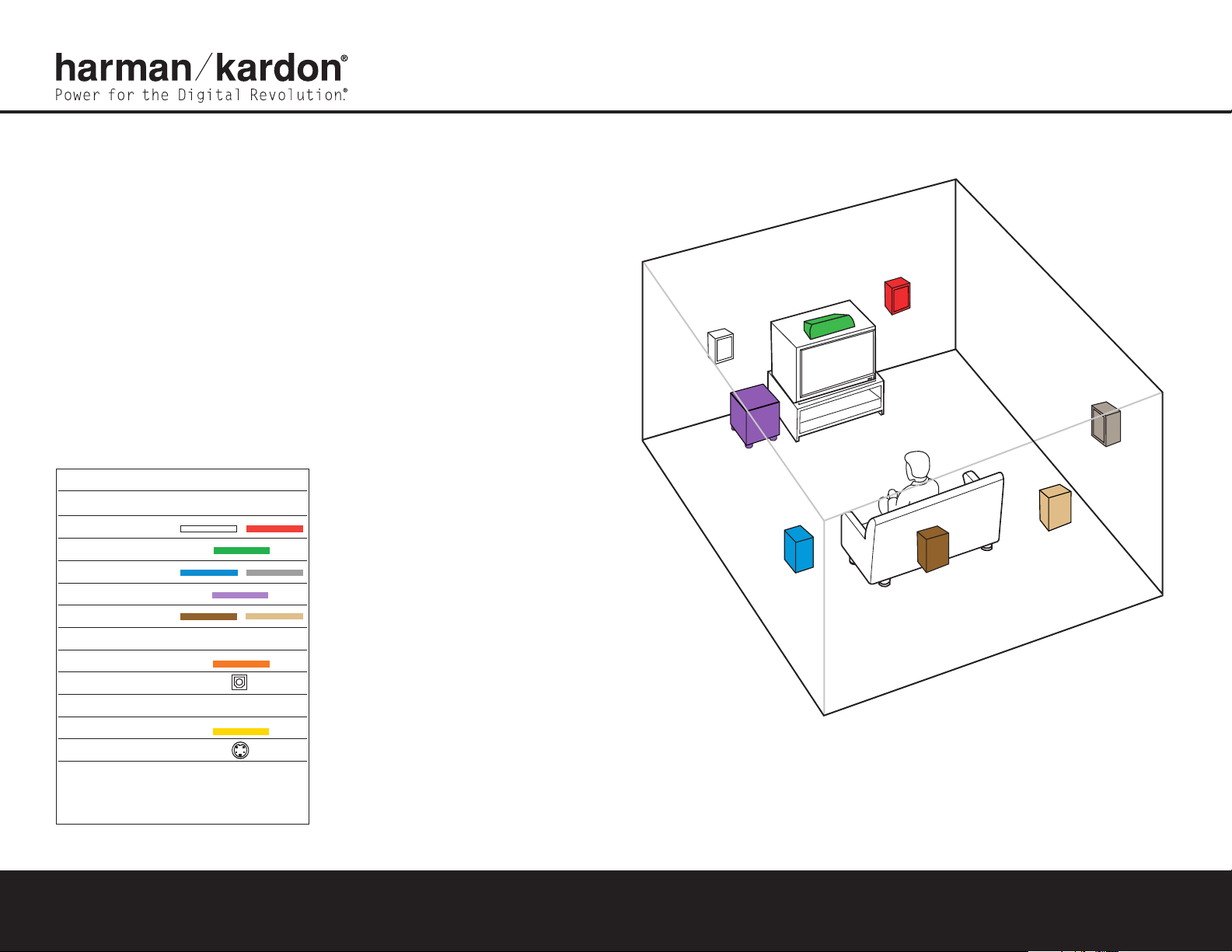
Figure 1 – Speaker Placement
The colors shown for each speaker correspond to
the matching output terminal connection on the
back of the AVR 635 (see page 8).
Connections Color Guide
Audio Connections Left Right
Front
Center
Surround
Subwoofer
Surround Back
Digital Audio Connections
Coaxial
Optical
Video Connections
Composite
S-Video
VR 635 to the appropriate
Match the colored jacks on the
jacks on your source equipment or speakers.The colors are
standardized,
but not all equipment or connectors use them.
A
AVR 635 QUICK-START GUIDE
Step 1. Place your speakers in the listening
room (see page 19).
SPEAKER PLACEMENT
Page 2
SURROUND BACK
LEFT SPEAKER
SURROUND BACK
RIGHT SPEAKER
FRONT RIGHT
SPEAKER
FRONT LEFT
SPEAKER
CENTER SPEAKER
SUBWOOFER
+
_
+
_
LINE IN/SUB/LFE
+
_
SURROUND
RIGHT SPEAKER
+
_
+
_
+
_
SURROUND
LEFT SPEAKER
+
_
AVR 635 QUICK-START GUIDE
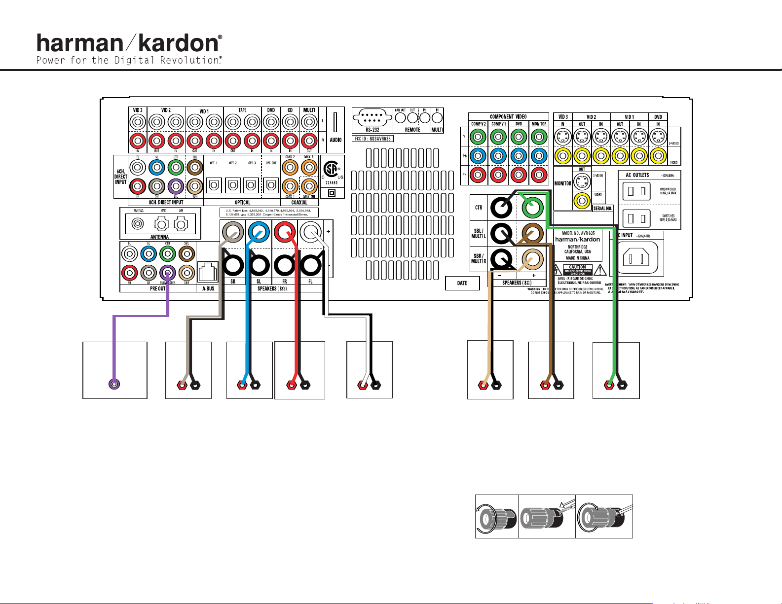
Figure 2 – Speaker Connections
Step 2. Connect the speakers to the receiver: red (+) on speaker to colored (+) on receiver and black (–) to black (–)
(see page 16).
Step 3. Connect the Subwoofer Pre-Out jack to the Line-In jack on your subwoofer.
You may adjust the settings on the subwoofer later as needed (see page 16).
Figure 3 – How to Use the Binding-Post
Speaker Terminal
Page 3

CD PLAYERAM ANTENNAFM ANTENNA
L R Optical Coax
REC/IN
PLAY/OUT
AUDIO RECORDER
Figure 4 – Audio Connections
Dashed lines (––––) indicate coaxial and optical
digital audio connections. Choose either type
(but not both) for each digital audio source.
Figure 5 – Connecting EzSet/EQ Microphone
Step 4. Connect AM and FM antennas (Fig. 4) (see page 16).
Step 5. Connect source components, as shown in Figures 4 and 5, and the
Device Connection Options chart on the back of this guide (see pages
16–17).
AUDIO connections: Right channel (red) on source to right (red)
on AVR, and left channel (
DIGITAL AUDIO connections, if available: Choose either coaxial
(orange) to coaxial (orange) OR optical to optical for each device.
The Coaxial 1 input defaults to the DVD player;
reassigned. Assign the other digital inputs and outputs as appropriate
for your equipment (see Step 7).
VIDEO connections: Choose component (Y/Pb/Pr – green/blue/
red), composite (yellow) or S-Video (4-pin) for each video source.
The DVD Component Video inputs default to the DVD player, but may
white) on source to left (white) on AVR.
, it may be
however
be reassigned. Connect the component, composite and S-Video
Monitor outputs to your Video Monitor (TV). Switch your TV set’s input
to match the type of video used for the currently selected source.
Step 6. Plug all components into AC power outlets. The outlets on the back of
the AVR 635 should be used
CD or DVD players, and the total should not exceed 100 watts.
Basic Receiver Configuration
Step 7. Select digital inputs: If your DVD is connected to Coaxial 1, no adjust-
ment is needed. For any other digital-device connections, use the
front-panel Digital Select button and the arrow buttons to select an
optical or coaxial digital input (see pages 21 and 35).
Plug the EzSet/EQ microphone into the Microphone Jack behind the
Step 8.
door on the front panel. Place the microphone at your preferred listening position and then follow the instructions on pages 24 to 26 of the
only for low-current products, such as
Owner’s Manual and the on-screen menus to run EzSet/EQ. Note that
you will hear a series of test tones and will then be instructed to move
the microphone and point it toward the three front speakers during the
second part of the calibration process.When the on-screen menu indicates that EzSet/EQ is complete, your system settings for speakers,
delay times, channel output and room equalization are entered into the
unit’s memory. Unplug the microphone and keep it for future use.
Your system is configured – sit back and enjoy.
Step 9.
SPEAKER AND AUDIO CONNECTIONS
Page 4

DVD PLAYER
VCR (Video 1)
I
n/Rec
Out/Play
L
R VIDEO
Component Video
Y
Pb
Pr
Optical Coax
L R Video S-Video
Cable Box or Satellite Receiver (Video 3)
OUT
L
R Video S-Video
O
ptical Coax
C
omponent Video
Y
Pb
P
r
TV or Video Display
IN
V
ideo S-Video Component Video
Y
Pb Pr
Power for the Digital Revolution
.
®
®
Figure 6 – Video Connections
Dashed lines (––––) indicate coaxial and optical digital audio connections. Choose either type (but not both) for each
digital audio source.
Dotted lines (
when available, but you may use any of the three types (but not more than one). When component, composite and
S-Video sources are connected to the AVR you must also connect all outputs from the AVR to your TV.
Device Connection Options: Recommended connections are shown in red, but connections may be made to best fit your system requirements. The Video 4, Coaxial 4 and Optical 4 inputs are on the front panel of the receiver.
Device Input Name Audio Input Connections Audio Output Connections Video Connections
CD Player CD CD L/R Inputs, Optical Digital 1, 2 or 3, or Coaxial Digital 1, 2 or 3 Not required Not required
DVD Player DVD Coaxial Digital 1, 2 or 3, Optical Digital 1, 2 or 3, or DVD L/R Inputs Not required DVD Component Video Input, DVD Composite or S-Video
VCR Video 1 Video 1 L/R Inputs Video 1 L/R Outputs Video 1 Composite or S-Video Input and Output
Cable Box or Satellite Receiver Video 3
Audio Recorder Tape Tape L/R Inputs, Optical Digital 1, 2 or 3, or Coaxial Digital 1, 2 or 3 Inputs Tape L/R Outputs, Digital Optical** or Coaxial Outputs** Not required
TV or Video Display Not applicable Not required Not required Monitor-Out Component, Composite and/or S-Video.
Check with your cable company to deter
*
mine whether digital audio is available for all channels
Video 3 L/R Inputs, Optical Digital 1, 2 or 3*, or Coaxial Digital 1, 2 or 3* Inputs
It may be necessar
.
y to make BOTH analog and digital connections if it is not.
••••) indicate component, composite or S-Video connections. Component video is the preferred connection
Not required Component V2, Video 3 Composite or S-Video
Digital audio recorders only
**
.
VIDEO CONNECTIONS
250 Crossways Park Drive,Woodbury, New York 11797 www.harmankardon.com ©2004 Harman International Industries, Incorporated Part No. ZKD1216HA00-5
 Loading...