

Page 1
harman/kardon
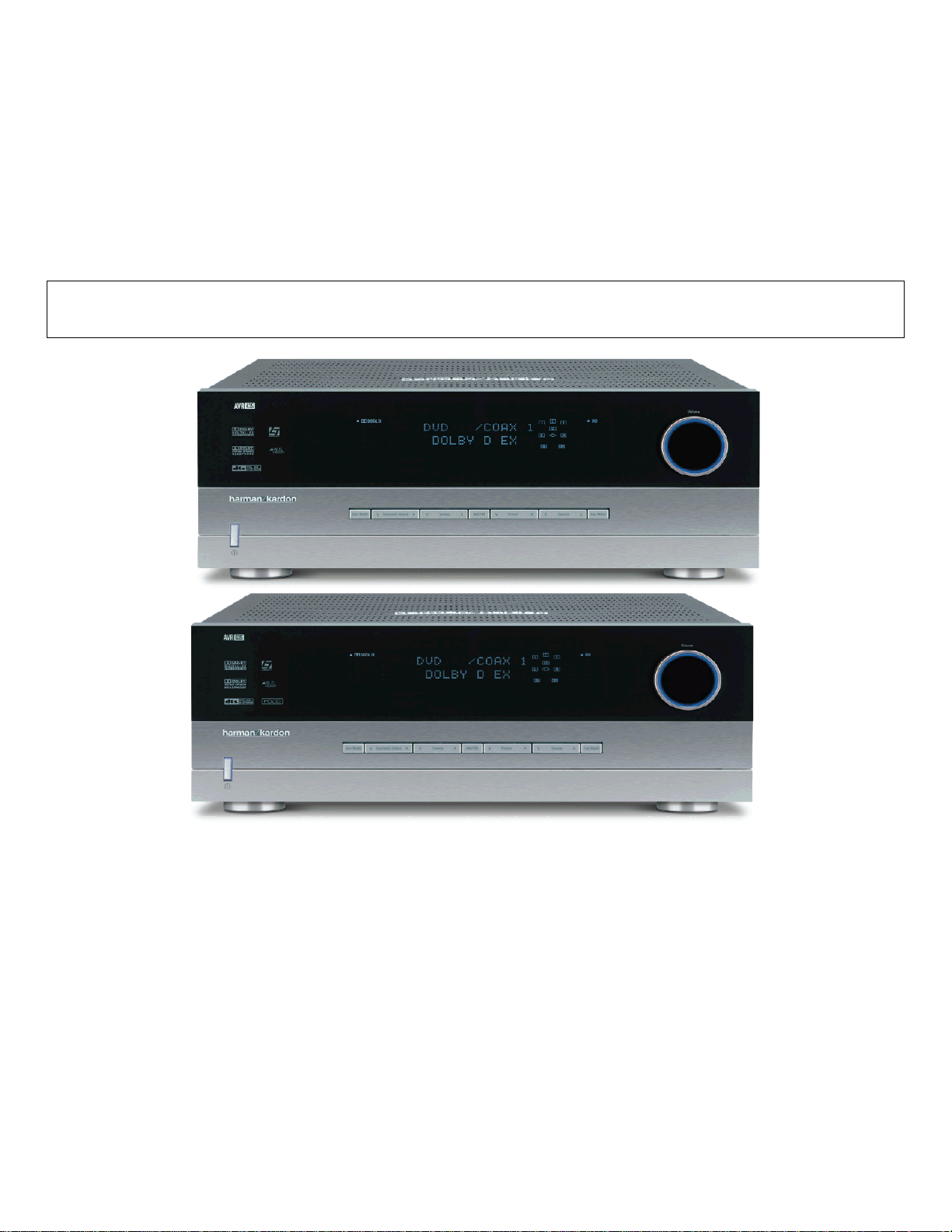
AVR435
7 X 65W 7.1 CHANNEL A/V RECEIVER
AVR635
7 X 75W 7.1 CHANNEL A/V RECEIVER
SERVICE MANUAL
PACKING………………………………..…….2
ESD WAR NI N G ……………………………….3
LEAKAGE TESTING……………….…...…....4
AVR435 BASIC SPECIFICATIONS…….…..5
AVR635 BASIC SPECIFICATIONS…….…..6
FRON T P A NE L C ON T R O L S ………..…...…..7
REAR PANEL CONNECTIONS……………10
REMOTE CONTROL FUNCTIONS………..13
INSTALLATION/CONNECTIONS………….17
OPERATION….……………………………...20
TROUBLESHOOTING GUIDE…...……..…26
PROCESSOR RESET……………….….…..26
Woodbur y, New York 11797 Rev1 6/ 2004
CONTENTS
EXPLODED VIEW…………………….….…27
MECHANICAL PARTS LI ST……………….28
TECH TIP HKTT2003-01…………………..30
IDLE ADJUSTMENT PROCEDURES…….31
BLOCK DIAGRAMS………………………..3 3
AVR435 PARTS LISTS……….…………....35
AVR635 PARTS LISTS………………….….54
SEMICONDUCTOR PINOUTS……………75
PCB DRAWINGS…………………………..117
SCHEMATICS………………………………128
WIRING D I A G R A M…………………………142
harman/kardon, Inc.
250 Crossways Park Dr.
Page 2
AVR435/635 harman/kardon
2
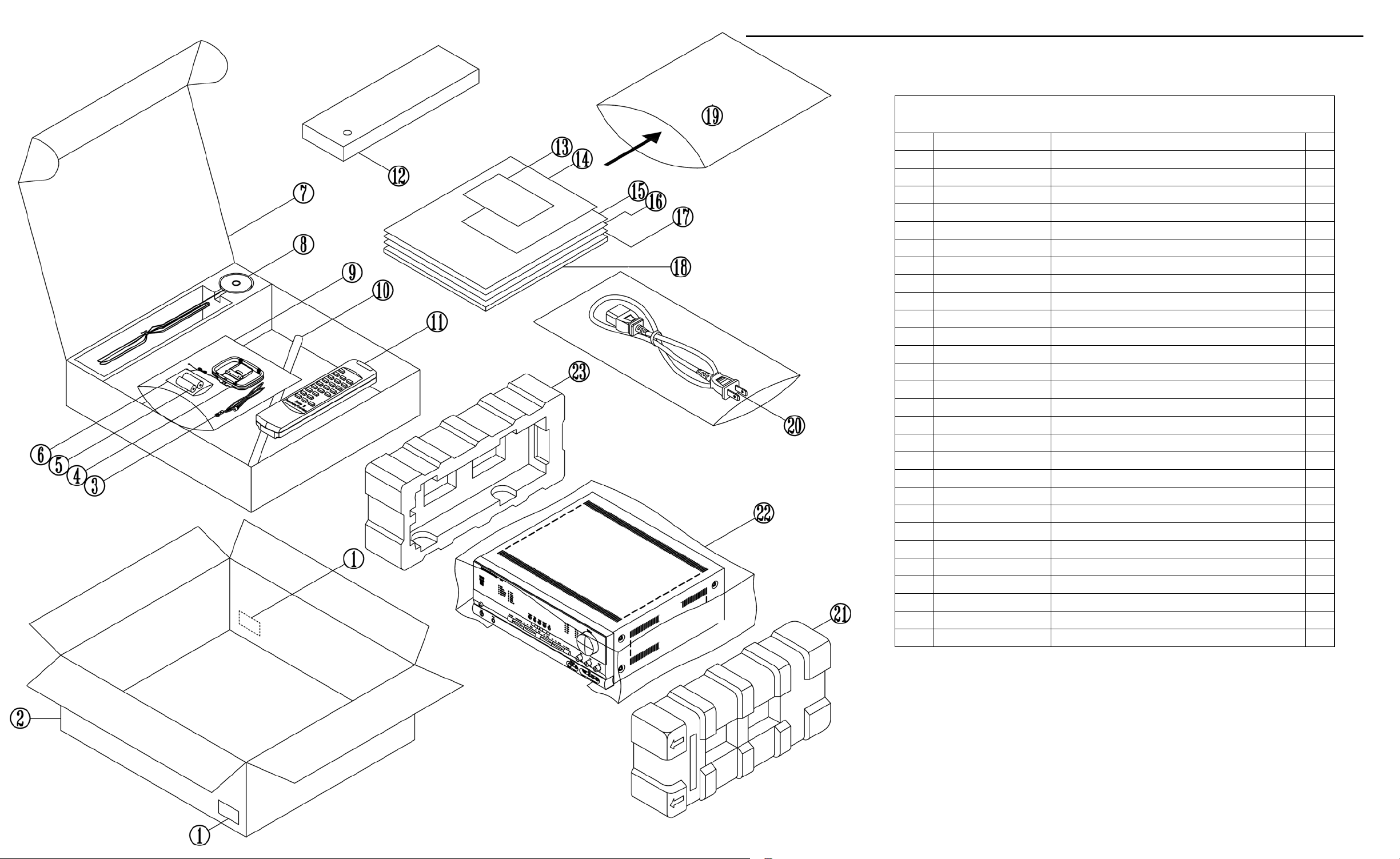
AVR435/635 PACKING PART LIST
Ref# Part Number Description Qty
LABEL BARCODE 2
1
ZKD1204HA00-7 BOX CARTON AVR635 US 1
2
ZKD1104HA00-2 BOX CARTON AVR435 US 1
H03-WAB01200203-4 ANTENNA WIRE 75 CT02-FM 1
3
H03-ATALF039ABK-5 ANTENNA WIRE ANTENNA LOOP CT01-AM 1
4
BATTERY ALKALINE 1.5V AAA 2
5
POLYBAG BATTERY 1
6
ZKD1202HA00-4 CARTON BOX MIC 1
7
H03-MCD12TWBKNN-8 AVR435/635 MICROPHONE ASSY 1
8
BAG PE 160X180MM 1
9
H03-ZPD1212INBK-5 MICROPHONE ASSY EXTENSION PIECE 1
10
H03-RYC1202HA00-0 REMOCON ZONE 2 1
11
RB18D01 REMOCON AVR635 1
12
RB18D00 REMOCON AVR435 1
ZKC1113HA00-9 CARD WARRANTY 1
13
ZKC1263HA00 INSERT RS232 NOTE PAPER 1
14
ZKD1216HA00-5 QUICK SETUP GUIDE AVR635 1
15
ZKD1116HA00-0 QUICK SETUP GUIDE AVR435 1
ZKC1214HA00 LABEL SAFETY LEAFLET 1
16
ZKD1263HA00 B ROCHURE A VR US 1
17
ZKD1201HA00-8 OWNER'S MANUAL AVR635 US 1
18
ZKD1101HA00-3 OWNER'S MANUAL AVR435 US 1
BAG PE 330 X 245 T0.05 1
19
H03-WAUSA2103BK-7 POWER CORD WS-004C+002E SJT#14*2C L=2M 1
20
ZQD1201HAWH-A CUSHION POLY EPS RIGHT 1
21
FILM SHEET PE 920 X 1000 0.3~0.7T 1
22
ZQD1202HAWH-6 CUSHION POLY EPS LEFT 1
23
Page 3
AVR435/635 harman/kardon
3
Some semiconductor (solid state) devices can be damaged easily by static electricity. Such components commonly are called
Electrostatically Sensitive (ES) Devices. Examples of typical ES devices are integrated circuits and some field effect transistors and
semiconductor "chip" components.
The following techniques should be used to help reduce the incidence of component damage caused by static electricity.
1. Immediately before handling any semiconductor component or semiconductor-equipped assembly, drain off any electrostatic charge on
your body by touching a known earth ground. Alternatively, obtain and wear a commercially available discharging wrist strap device,
which should be removed for potential shock reasons prior to applying power to the unit under test.
2. After removing an electrical assembly equipped with ES devices, place the assembly on a conductive surface such as aluminum foil, to
prevent electrostatic charge build-up or exposure of the assembly.
3. Use only a grounded-tip soldering iron to solder or unsolder ES devices.
4. Use only an anti-static solder removal device. Some solder removal devices not classified as "anti-static" can generate electrical charges
sufficient to damage ES devices.
5. Do not use freon-propelled chemicals. These can generate electrical change sufficient to damage ES devices.
6. Do not remove a replacement ES device from its protective package until immediately before you are ready to install it. (Most replacement
ES devices are packaged with leads electrically shorted together by conductive foam, aluminum foil or comparable conductive material.)
7. Immediately before removing the protective material from the leads of a replacement ES device, touch the protective material to the
chassis or circuit assembly into which the device will be installed.
CAUTION :
8. Minimize bodily motions when handling unpackaged replacement ES devices. (Otherwise harmless motion such as the brushing together
or your clothes fabric or the lifting of your foot from a carpeted floor can generate static electricity sufficient to damage an ES devices.
Be sure no power is applied to the chassis or circuit, and observe all other safety precautions.
Each precaution in this manual should be followed during servicing.
Components identified with the IEC symbol in the parts list are special significance to safety. When replacing a component identified with
, use only the replacement parts designated, or parts with the same ratings or resistance, wattage, or voltage that are designated in the
parts list in this manual. Leakage-current or resistance measurements must be made to determine that exposed parts are acceptably
insulated from the supply circuit before retuming the product to the customer.
Page 4
AVR435/635 harman/kardon
4
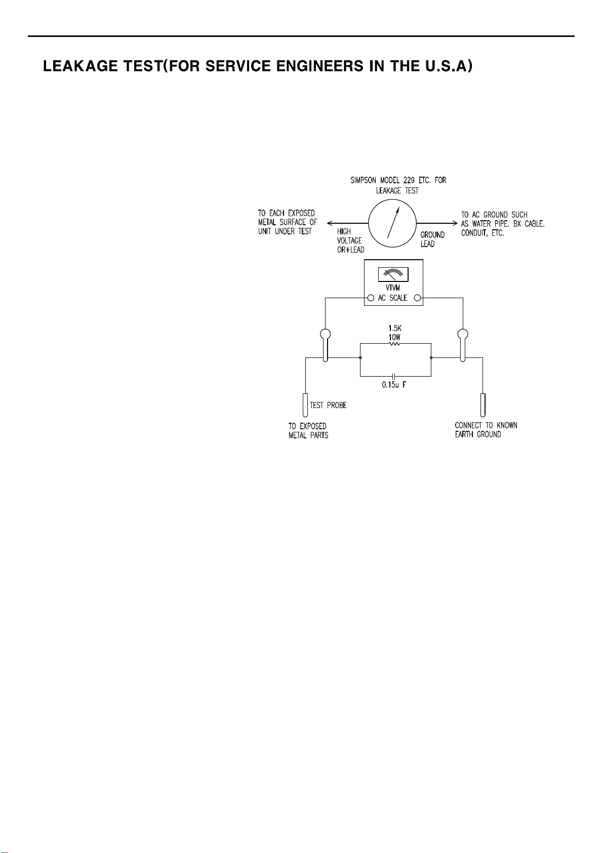
Before returning the unit to the user, perform the following safety checks :
1. Inspect all lead dress to make certain that
leads are not pinched or that hardware is not
lodged between the chassis and other metal
parts in the unit.
2. Be sure that any protective devices such as
nonmetallic control knobs, insulating fish-
papers, cabinet backs, adjustment and
compartment covers or shields, isolation
resistor-capacity networks, mechanical
insulators, etc. Which were removed for the
servicing are properly re-installed.
3. Be sure that no shock hazard exists ; check for leakage
current usingSimpson Model 229 Leakage Tester, standard
equipment item No. 21641, RCA Model WT540A or use
alternate method as follows : Plug the power cord directly
Into a 120 volt AC receptacle (do not use an Isolation
Transformer for this test). Using two clip leads, connect a
1500 ohms,10watt Resistor paralleledby a 0.15uFcapacitor, in serieswith all exposedmetal cabinet partsand a knownearth ground, such
as a water pipe or conduit. Use a VTVM or VOM with 1000 ohms per volt, or higher sensitivity to measure the AC voltage drop across the
resistor. (See diagram) Move the resistor connection to each exposed metal part having a return path to the chassis (antenna, metal,
cabinet, screwheads, knobsand control shafts, escutcheon, etc.) and measurethe ACvoltage drop across the resistor. (Thistest should be
performed withthe 0.35 volt RMS ormore is excessive and indicates a potential shockhazard which must be correctedbefore returning the
unit to the owner.
Page 5

AVR435/635 harman/kardon
5
AVR 435 TECHNICAL SPECIFICATIONS
AVR 435 TECHNICAL SPECIFICATIONS
Audio Section
Stereo Mode
Continuous Average Power (FTC)
80 Watts per channel, 20Hz–20kHz,
@ <0.07% THD, both channels driven into 8 ohms
Seven-Channel Surround Modes
Power per Individual Channel
Front L&R channels:
65 Watts per channel
@ <0.07% THD, 20Hz–20kHz into 8 ohms
Center channel:
65 Watts @ <0.07% THD, 20Hz–20kHz into 8 ohms
Surround (L & R Side, L & R back) channels:
65 Watts per channel
@ <0.07% THD, 20Hz–20kHz into 8 ohms
Input Sensitivity/Impedance
Linear (High-Level) 200mV/47k ohms
Signal-to-Noise Ratio (IHF-A) 100dB
Surround System Adjacent Channel Separation
Pro Logic I/II 40dB
Dolby Digital (AC-3) 55dB
DTS 55dB
Frequency Response
@ 1W (+0dB, –3dB) 10Hz –130kHz
High Instantaneous
Current Capability (HCC) ±40 Amps
Transient Intermodulation
Distortion (TIM) Unmeasurable
Slew Rate 40V/µsec
FM Tuner Section
Frequency Range 87.5–108.0MHz
Usable Sensitivity IHF 1.3µV/13.2dBf
Signal-to-Noise Ratio Mono/Stereo 70/68dB
Distortion Mono/Stereo 0.2/0.3%
Stereo Separation 40dB @ 1kHz
Selectivity ±400kHz, 70dB
Image Rejection 80dB
IF Rejection 90dB
AM Tuner Section
Frequency Range 520–1720kHz
Signal-to-Noise Ratio 45dB
Usable Sensitivity Loop 500µV
Distortion 1kHz, 50% Mod 0.8%
Selectivity ±10kHz, 30dB
Video Section
Television Format NTSC
Input Level/Impedance 1Vp-p/75 ohms
Output Level/Impedance 1Vp-p/75 ohms
Video Frequency Response
(Composite and S-Video) 10Hz–8MHz (–3dB)
Video Frequency Response
(Component Video) 10Hz–50MHz (–3dB)
General
Power Requirement AC 120V/60Hz
Power Consumption 59W at Power On, idle; 1,000W at rated power output
(7 channels driven)
Dimensions Product Shipping
Width 17.3 inches (440mm) 20.1 inches (510mm)
Height 6.5 inches (165mm) 10 inches (254mm)
Depth 17.1 inches (435mm) 22.2 inches (565mm)
Weight 39 lb (18.6kg) 45 lb (21.4kg)
Depth measurement includes knobs, buttons and terminal connections.
Height measurement includes feet and chassis.
All features and specifications are subject to change without notice.
Harman Kardon, Power for the Digital Revolution and Logic 7 are registered trademarks of
Harman International Industries, Incorporated.
is a trademark of Harman International Industries, Incorporated.
*Manufactured under license from Dolby Laboratories. “Dolby,” “Pro Logic”and the
Double-D symbol are trademarks of Dolby Laboratories.
DTS, DTS Surround, DTS-ES, DTS 96/24 and DTS Neo:6 are registered trademarks of
Digital Theater Systems, Inc.
A-BUS and A-BUS Ready are registered trademarks of Leisure Tech Electronics Pty Ltd Australia.
SACD is a trademark of Sony Electronics Inc.
TiVo is a registered trademark of TiVo, Inc.
Replay TV is a registered trademark of Digital Networks North America, Inc.
Supplied Accessories
The following accessory items are supplied with the AVR 435. If any of these items are missing, please contact Harman Kardon customer service at www.harmankardon.com.
• A system remote control • An AM loop antenna
• A Zone II remote control • An FM wire antenna
• An microphone • Six AAA batteries
• Extender rod for microphone
TECHNICAL SPECIFICATIONS 55
TECHNICAL SPECIFICATIONS 55
Page 6

AVR435/635 harman/kardon
6
AVR 635 TECHNICAL SPECIFICATIONS
AVR 635 TECHNICAL SPECIFICATIONS
Audio Section
Stereo Mode
Continuous Average Power (FTC)
90 Watts per channel, 20Hz–20kHz,
@ <0.07% THD, both channels driven into 8 ohms
Seven-Channel Surround Modes
Power per Individual Channel
Front L&R channels:
75 Watts per channel
@ <0.07% THD, 20Hz–20kHz into 8 ohms
Center channel:
75 Watts @ <0.07% THD, 20Hz–20kHz into 8 ohms
Surround (L & R Side, L & R back) channels:
75 Watts per channel
@ <0.07% THD, 20Hz–20kHz into 8 ohms
Input Sensitivity/Impedance
Linear (High-Level) 200mV/47k ohms
Signal-to-Noise Ratio (IHF-A) 100dB
Surround System Adjacent Channel Separation
Pro Logic I/II 40dB
Dolby Digital (AC-3) 55dB
DTS 55dB
Frequency Response
@ 1W (+0dB, –3dB) 10Hz –130kHz
High Instantaneous
Current Capability (HCC) ±50 Amps
Transient Intermodulation
Distortion (TIM) Unmeasurable
Slew Rate 40V/µsec
FM Tuner Section
Frequency Range 87.5–108.0MHz
Usable Sensitivity IHF 1.3µV/13.2dBf
Signal-to-Noise Ratio Mono/Stereo 70/68dB
Distortion Mono/Stereo 0.2/0.3%
Stereo Separation 40dB @ 1kHz
Selectivity ±400kHz, 70dB
Image Rejection 80dB
IF Rejection 90dB
AM Tuner Section
Frequency Range 520–1720kHz
Signal-to-Noise Ratio 45dB
Usable Sensitivity Loop 500µV
Distortion 1kHz, 50% Mod 0.8%
Selectivity ±10kHz, 30dB
Video Section
Television Format NTSC
Input Level/Impedance 1Vp-p/75 ohms
Output Level/Impedance 1Vp-p/75 ohms
Video Frequency Response
(Composite and S-Video) 10Hz–8MHz (–3dB)
Video Frequency Response
(Component Video) 10Hz–50MHz (–3dB)
General
Power Requirement AC 120V/60Hz
Power Consumption 59W at Power On, idle; 1,000W at rated power output
(7 channels driven)
Dimensions Product Shipping
Width 17.3 inches (440mm) 20.1 inches (510mm)
Height 6.5 inches (165mm) 10 inches (254mm)
Depth 17.1 inches (435mm) 22.2 inches (565mm)
Weight 41 lb (18.6kg) 47 lb (21.4kg)
Depth measurement includes knobs, buttons and terminal connections.
Height measurement includes feet and chassis.
All features and specifications are subject to change without notice.
Harman Kardon, Power for the Digital Revolution and Logic 7 are registered trademarks of
Harman International Industries, Incorporated.
is a trademark of Harman International Industries, Incorporated.
*Manufactured under license from Dolby Laboratories. “Dolby,” “Pro Logic”and the
Double-D symbol are trademarks of Dolby Laboratories.
DTS, DTS Surround, DTS-ES, DTS 96/24 and DTS Neo:6 are registered trademarks of
Digital Theater Systems, Inc.
HDCD system manufactured under license from Pacific Microsonics, Inc. This product is
covered by one or more of the following: in the USA: 5,479,168;
5,638,074; 5,640,161; 5,808,574; 5,838,274; 5,854,600; 5,864,311;
5,872,531; and in Australia: 669114. Other patents pending.
A-BUS and A-BUS Ready are registered trademarks of Leisure Tech Electronics Pty Ltd Australia.
TiVo is a registered trademark of TiVo, Inc.
Replay TV is a registered trademark of Digital Networks North America, Inc.
Supplied Accessories
The following accessory items are supplied with the AVR 635. If any of these items are missing, please contact Harman Kardon customer service at www.harmankardon.com.
• A system remote control • An AM loop antenna
• A Zone II remote control • An FM wire antenna
• An microphone • Six AAA batteries
• Extender rod for microphone
TECHNICAL SPECIFICATIONS 55
TECHNICAL SPECIFICATIONS 55
Page 7
2
4
5
6
7
9
!
@
#
%
3
8
A
B
D
E
F
G
HH
I
JK LLN
M
)
$
^
1
C
A
VR 635
2
4
5
6
7
9
!
@
#
%
3
8
A
B
D
E F
G
HH
I
JK LLN
M
)
$
^
1
C
AVR435/635 harman/kardon
7
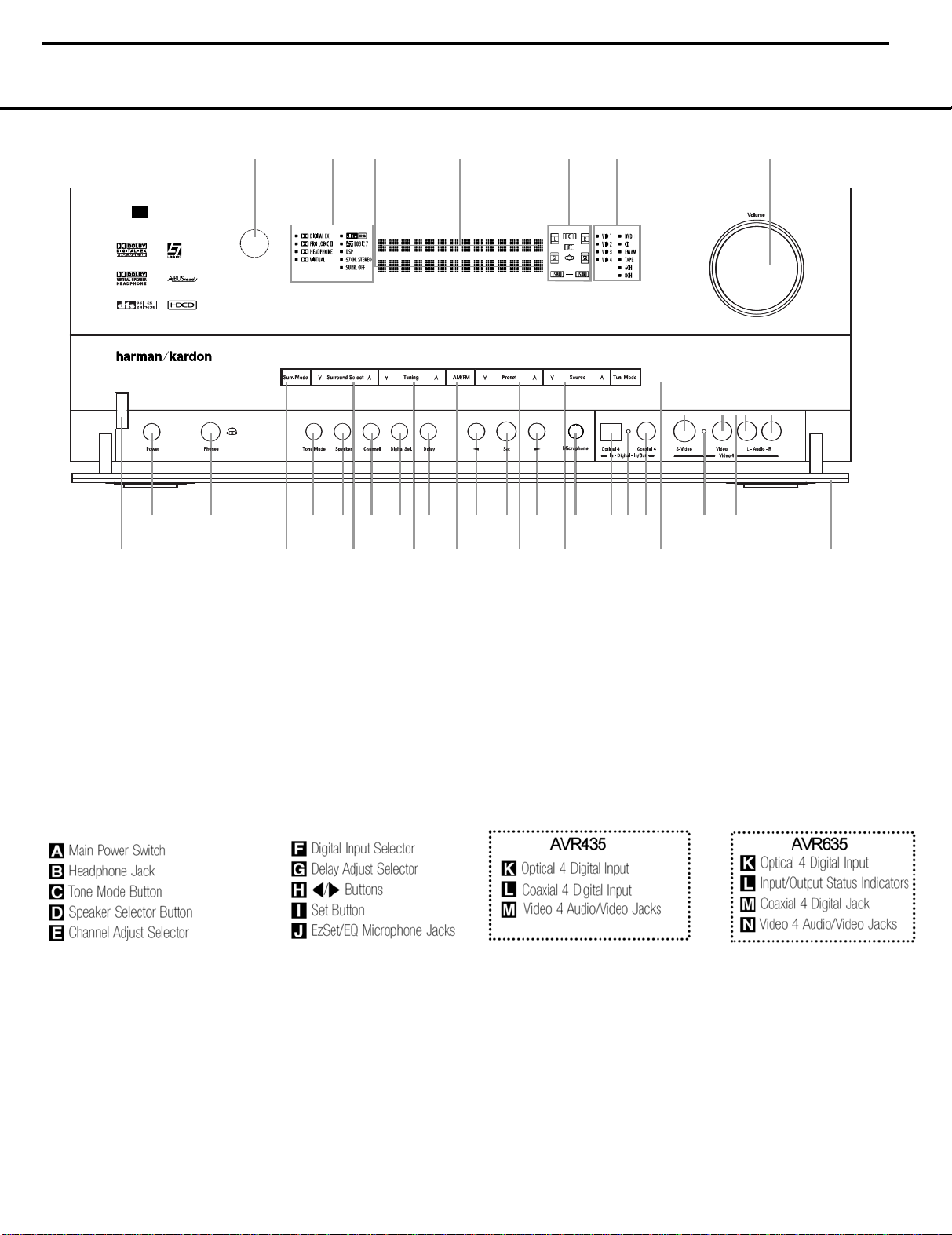
FRONT-PANEL CONTROLS
= AVR635 only
FRONT-PANEL CONTROLS
NOTE: To make it easier to follow the instructions that refer to this illustration, a larger copy may be downloaded from the Product Support section for this product at
www.harmankardon.com.
The following controls and indicators are available on the AVR 635’s front panel:
1 Standby/On Switch
2 Surround Mode Group Selector
3 Surround Mode Selector
4 Tuning Selector
5 Tuner Band Selector
6 Preset Station Selector
The following controls and jacks are located behind the front-panel door. To open the door, place the edge of a finger on the left or right edge of the panel and gently swing the
door down towards you.
1 Standby/On Switch: When the Main Power
A
Switch
AVR 635; press it again to turn the unit off. Note that
the illumination surrounding the switch will turn blue
when the unit is on.
2 Surround Mode Group Selector: Press this but-
ton to select the top-level group of surround modes.
Each press of the button will select one of the surround mode categories. Once the button is pressed so
is “ON,” press this button to turn on the
7 Input Source Selector
8 Tuning Mode Selector
9 Front-Panel Control Door
) Volume Control
! Input Indicators
@ Speaker/Channel Input Indicators
that the name of the desired surround mode category
appears in the on-screen display and in the
Display Line
Selector
available. For example, press this button to select Dolby
modes, and then press the
3 to choose from the various mode options.
3 Surround Mode Selector: Press this button
to select from among the available surround mode
$, press the Surround Mode
3 to cycle through the individual modes
Surround Mode Selector
Lower
# Upper Display Line
$ Lower Display Line
% Surround Mode Indicators
^ Remote Sensor Window
options for the surround mode category selected.
The specific modes will vary based on the number of
speakers available, the surround mode category and
whether the input source is digital or analog. For example, press the
to select a category such as Dolby or Logic 7, and
then press this button to see the specific mode choices
that are available. For more information on mode
selection, see page 34.
Surround Mode Group Selector 2
FRONT-PANEL CONTROLS 55
Page 8

AVR435/635 harman/kardon
8
FRONT-PANEL CONTROLS
4 Tuning Selector: Press the left side of the button
to tune lower-frequency stations and the right side of
the button to tune higher-frequency stations. When
the tuner is in the
each tap of the Selector will increase or decrease the
frequency by one increment. When the tuner receives
a strong-enough signal for adequate reception,
MANUAL TUNED will appear in the Lower
Display Line
the tuner is in the
press the button once, and the tuner will scan for a
station with acceptable signal strength. When the
next higher- or lower-frequency station with a strongenough signal is tuned, the frequency scan will stop
and the
display will indicate
FM Stereo station is tuned, the display will read
AUTO ST TUNED. See page 37 for more
information on using the tuner.
5 Tuner Band Selector: Pressing this button will
automatically switch the AVR 435 to the Tuner mode.
Pressing it again will switch between the AM and FM
frequency bands. (See page 37 for more information
on the tuner.)
6 Preset Station Selector: Press this button to
scroll up or down through the list of stations that have
been entered into the preset memory. (See page 37
for more information on tuner programming.)
7 Input Source Selector: Press this button to
change the input by scrolling up or down through the
list of input sources.
8 Tuning Mode Selector: Press this button to select
Auto or Manual tuning. When the button is pressed so
that
AUTO/STEREO appears in the Upper
Display Line
station with an acceptable signal when the
Selector
pressed so that
Upper Display Line #, each press of the Tuning
Selector
page 37 for more information on using the tuner.) This
button may also be used to switch between Stereo and
Mono modes for FM radio reception. When weak
MANUAL/MONO mode,
$ and in the on-screen display.When
AUTO/STEREO mode,
Lower Display Line $ and the on-screen
AUTO TUNED. When an
#, the tuner will search for the next
Tuning
4wéis pressed. When the button is
MANUAL/MONO appears in the
4wéwill increase the frequency. (See
reception is encountered, select the Manual/Mono
tuning mode. Press and hold again to switch back to
Stereo mode. (See page 37 for more information on
using the tuner.)
9 Front-Panel Control Door: To open the door so
that the front-panel jacks and controls behind this door
may be accessed, gently pull the door down and
towards you using either upper corner of the door.
) Volume Control: Turn this knob clockwise to
increase the volume, counterclockwise to decrease the
volume. If the AVR 435 is muted, adjusting the volume
control will automatically release the unit from the
silenced condition.
! Input Indicators: One of these indicators will light
to identify the currently selected input. Note that the
entire list will light briefly each time the unit is turned
on as a test.
@ Speaker/Channel Input Indicators: These indi-
cators are multipurpose, indicating both the speaker
type selected for each channel and the incoming datasignal configuration. The left, center, right, right surround
and left surround speaker indicators are composed of
three boxes, while the subwoofer is a single box. The
center box lights when a “small” speaker is selected,
and the two outer boxes light when “large” speakers are
selected. When none of the boxes are lit for the center,
surround or subwoofer channels, no speaker has been
assigned that position. (See page 26 for more informa-
tion on configuring speakers.) The letters inside each
box displays the active input channels. For standard
analog inputs, only the L and R will light, indicating a
stereo input. For a digital source, the indicators will light
to display the channels being received at the digital
input. When the letters flash, the digital input has been
interrupted. (See page 36 for more information on the
Channel Indicators.)
# Upper Display Line: Depending on the unit’s
status, a variety of messages will appear here. In
normal operation, this line will show the current input
source and identify whether an analog or digital input
is in use.When the tuner is selected as the input, this
line will identify the station as AM or FM and show the
frequency and preset number, if any.
$ Lower Display Line: Depending on the unit’s
status, a variety of messages will appear here. In normal operation, the current surround mode will appear
on this line.
% Surround Mode Indicators: One of these
indicators will light to show the surround mode in
use. Depending on the specific combination of input
sources and surround mode selected, more than
one indicator may light. (See page 34 for more
information.)
^ Remote Sensor Window: The sensor behind
this window receives infrared signals from the remote
control. Aim the remote at this area and do not block
or cover it unless an external remote sensor is
installed.
6 FRONT-PANEL CONTROLS
Page 9

A
B
D
E
F
G
HH
I
J
L
MN
C
L
K
AVR435/635 harman/kardon
9
= AVR635 Only
The following controls and jacks are located behind the front-panel door. To open the door, place the edge of a finger on the left or right edge of the panel and gently swing the
door down towards you.
A Main Power Switch: Press this switch to apply
power to the AVR 635. When the switch is pressed
in, the unit is placed in a Standby mode, as indicated
by the amber illumination surrounding the
Switch
1. This button MUST be pressed in to
operate the unit. To turn the unit off and prevent the
use of the remote control, this switch should be
pressed until it pops out from the front panel so that
the word “OFF” may be read at the top of the switch.
NOTE: This switch is normally left in the “ON” position.
B Headphone Jack: This jack may be used to lis-
ten to the AVR 635’s output through a pair of headphones. Be certain that the headphones have a standard 1/4" stereo phone plug, or that you use an
adaptor, as needed, to convert the plug on your headphones to the 1/4" jack used on the AVR.When the
headphone jack is in use, the main room speakers will
automatically be turned off and the unit will output a
standard stereo signal. You may also use one of the
Dolby Headphone modes for an enhanced listening
experience. For more information on headphone lis-
tening, see page 33.
C Tone Mode Button: This button controls the tone
mode settings, enabling adjustment of the bass and
treble boost/cut. You may also use it to take the tone
controls out of the signal path completely for “flat”
response.The first press of the button displays a
TONE MODE message in the Lower Display
Line
$ and in the on-screen display.To take the
controls out of the signal path, press either of the
‹/› Buttons H until the display reads TONE
OUT
. To change the bass or treble settings, press
the button again until the desired option appears in the
Lower Display Line $ and in the on-screen display
and then press either of the
enter the desired boost or cut setting. See page 32
for more information on the tone controls.
‹/› Buttons H to
Standby/On
D Speaker Selector Button: Press this button to
begin the process of configuring the AVR 635 for the
type of speakers it is being used with. For complete
information on configuring the speaker settings, see
page 27.
E Channel Adjust Selector: Press the button to
begin the process of adjusting the channel level outputs using the source currently playing through your
AVR. For complete information on adjusting the chan-
nel output level, see page 30.
F Digital Input Selector: Press this button to begin
the process of selecting a digital source for use with
the currently selected input. Once the button has been
pressed, use the
desired input and then press the
enter the setting into the unit’s memory. See page 33
for more information on digital audio.
G Delay Adjust Selector: Press this button to begin
the process of adjusting the delay settings for Dolby
surround modes. See page 29 for more information
on delay adjustments.
H‹/› Buttons: When making system configura-
tion changes using the front-panel controls, press
these buttons to scroll through the available choices
for the option being adjusted.
I Set Button: When making system configuration
changes using the front-panel controls, press this button to enter a setting into the unit’s memory.
J EzSet/EQ Microphone Jack: Before starting the
EzSet/EQ automated setup process, plug the microphone into this jack. The microphone does not need
to be plugged in at other times.
K Optical 4 Digital Input: Connect the optical digital
output of an audio or video product to this jack.
‹/› Buttons H to choose the
Set Button I to
FRONT-PANEL CONTROLS
L Input/Output Status Indicators: These LED
indicators will normally light green to show that the
front-panel
Input/Output Jacks
these jacks are configured for use as an output, the
appropriate indicator will turn red to show that the jack
may be used as an output for recording. (See page 38
for more information on configuring the front-panel
jacks as outputs, rather than inputs.)
M Coaxial 4 Digital Jack: Connect the coaxial digital input or output for a digital audio product such as a
portable audio player or video game to this jack. The
jack is normally an input, but may be switched to an
output for recording using the menu system. See page
38 for more information.
N Video 4 Input/Output Jacks: These audio/video
jacks may be used as either an input or output for
temporary connection to video games or portable
audio/video products such as camcorders and
portable audio players. (See page 38 for more
information on switching these jacks between an
input and output.)
Coaxial 3 Digital Jack L and Video 4
M are operating as inputs.When
AVR635 Only
FRONT-PANEL CONTROLS 7
Page 10
48
49
50
51
47
46
45
44
48
49
50
51
47
46
45
44
43
48
49
50
51
47
46
45
44
43
42
41
51
47
404150
51
47
46
39
40
41
49
50
51
47
46
45
38
39
40
41
48
49
50
51
47
46
45
44
413751
47
40
41
37
36
50
51
47
46
39
40
41
37
36
35
49
50
51
47
46
45
38
39
40
41
37
36
35
34
48
49
50
51
47
46
45
44
38
39
40
41
37
36
35
34
33
48
49
50
51
47
46
45
44
43
38
39
40
41
37
36
35
34
33
32
48
49
50
51
47
46
45
44
43
42
38
39
40
41
31
37
3
6
35
34
33
32
48
49
50
51
47
4
6
45
44
43
42
435
AVR435/635 harman/kardon
10
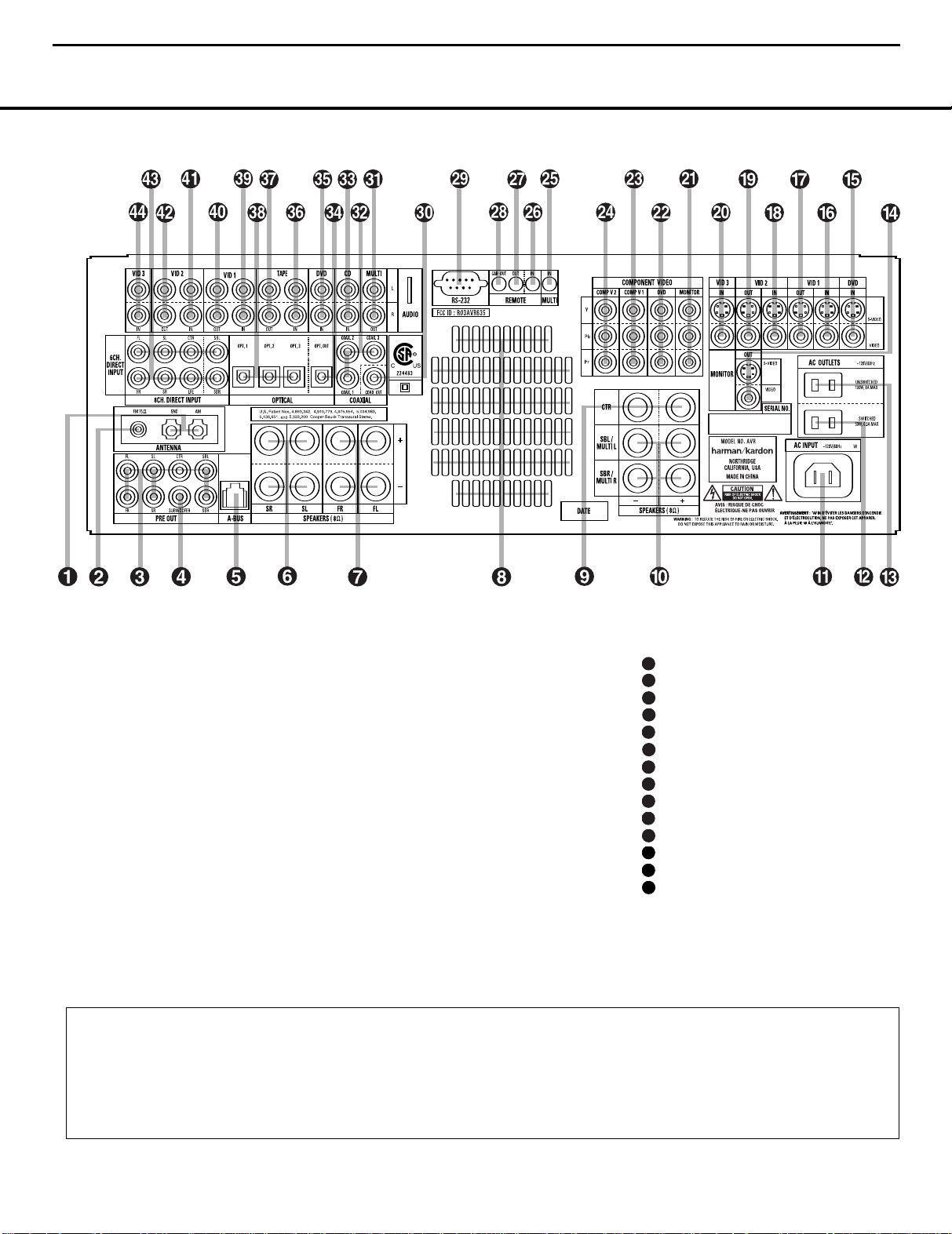
REAR-PANEL CONNECTIONS
REAR-PANEL CONNECTIONS
¡ AM Antenna
™ FM Antenna
£ Preamp Outputs
¢ Subwoofer Output
∞ A-BUS Connector
§ Surround Speaker Outputs
¶ Front Speaker Outputs
• Fan Vents
ª Center Speaker Outputs
‚ Surround Back/Multiroom Speaker Outputs
⁄ AC Power Cord
¤ Switched AC Accessory Outlet
‹ Unswitched AC Accessory Outlet
› Video Monitor Outputs
fi DVD Video Inputs
fl Video 1 Video Inputs
‡ Video 1 Video Outputs
° Video 2 Video Inputs
· Video 2 Video Outputs
a Video 3 Video Inputs
b Component Video Monitor Outputs
c DVD Component Video Inputs
d Component Video 1 Inputs
e Component Video 2 Inputs
f Multiroom IR Input
g Remote IR Input
h Remote IR Output
i Remote IR Carrier Output
j RS-232 Port
k Coaxial Digital Audio Output
Multiroom Audio Outputs
Coaxial Digital Audio Inputs
CD Audio Inputs
Optical Digital Audio Output
DVD Audio Inputs
Tape Inputs
Tape Outputs
Optical Digital Audio Inputs
Video 1 Audio Inputs
Video 1 Audio Outputs
Video 2 Audio Inputs
Video 2 Audio Outputs
8-Channel Direct Inputs
Video 3 Audio Inputs
NOTE: To make it easier to follow the instructions that refer to this illustration, a larger copy may be downloaded from the Product Support section for this product at
www.harmankardon.com.
NOTE: To assist in making the correct connections for
multichannel input, output and speaker connections,
all connection jacks and terminals are color-coded
as follows:
Front Left: White
Front Right: Red
Center: Green
8 REAR-PANEL CONNECTIONS
8 REAR-PANEL CONNECTIONS
Surround Left: Blue
Surround Right: Gray
Surround Back Left: Brown
Surround Back Right: Tan
Subwoofer: Purple
Coaxial Digital Audio: Orange
Composite Video: Yellow
Component Video “Y”: Green
Component Video “Pr”: Red
Component Video “Pb”: Blue
Optical Digital In: Black
Optical Digital Out: Gray
Page 11

AVR435/635 harman/kardon
11
REAR-PANEL CONNECTIONS
¡ AM Antenna: Connect the AM loop antenna sup-
plied with the receiver to these terminals. If an external
AM antenna is used, make connections to the
GND terminals in accordance with the instructions supplied with the antenna.
™ FM Antenna: Connect the supplied indoor or an
optional external FM antenna to this terminal.
£ Preamp Outputs: Connect these jacks to an
optional, external power amplifier for applications
where higher power is desired.
¢ Subwoofer Output: Connect this jack to the line-
level input of a powered subwoofer. If an external subwoofer amplifier is used, connect this jack to the subwoofer amplifier input.
∞ A-BUS Connector:
A-BUS®-certified remote room product to extend the
multiroom capabilities of your AVR 435. See page 17
for more information on A-BUS.
§ Surround Speaker Outputs: Connect these outputs to the matching + and – terminals on your surround channel speakers. In conformance with the CEA
color-code specification, the blue terminal is the positive (+) terminal that should be connected to the red
(+) terminal on the Surround Left speaker with older
color-coding, while the gray terminal should be connected to the red (+) terminal on the Surround Right
speaker with the older color-coding. Connect the black
(–) terminal on the AVR to the matching black negative (–) terminals for each surround speaker. (See
page 16 for more information on speaker polarity.)
¶ Front Speaker Outputs: Connect these outputs
to the matching + or – terminals on your left and right
speakers.When making speaker connections, always
make certain to maintain correct polarity by connecting
the color-coded (white for front left and red for front
right) (+) terminals on the AVR 435 to the red (+)
terminals on the speakers and the black (–) terminals
on the AVR 435 to the black (–) terminals on the
speakers. See page 16 for more information on
speaker polarity.
• Fan Vents: These ventilation holes are the output
of the AVR 435’s airflow system. To ensure proper
operation of the unit and to avoid possible damage to
delicate surfaces, make certain that these holes are
not blocked and that there is at least 3 inches of open
space between the vent holes and any wooden or fabric surface. It is normal for the fan to remain off at
most normal volume levels. An automatic temperature
sensor turns the fan on only when it is needed.
Connect this jack to an optional
AM and
ª Center Speaker Outputs: Connect these outputs
to the matching + and – terminals on your center
channel speaker. In conformance with the CEA colorcode specification, the green terminal is the positive
(+) terminal that should be connected to the red (+)
terminal on speakers with the older color-coding.
Connect the black (–) terminal on the AVR to the
black negative (–) terminal on your speaker. (See
page 16 for more information on speaker polarity.)
‚ Surround Back/Multiroom Speaker Outputs:
These speaker terminals are normally used to power
the surround back left/surround back right speakers
in a 7.1-channel system. However, they may also be
used to power the speakers in a second zone, which
will receive the output selected for a multiroom system.
To change the output fed to these terminals from
the default of the Surround Back speakers to the
Multiroom Output, you must change a setting in the
Advanced Menu of the OSD system. See page 41 for
more information on configuring this speaker output. In
normal surround system use, the brown and black terminals are the surround back left channel positive (+)
and negative (–) connections and the tan and black
terminals are the surround back right positive (+) and
negative (–) terminals. For multiroom use, connect the
brown and black SBL terminals to the red and black
connections on the left remote zone speaker and connect the tan and black SBR terminals to the red and
black terminals on the right remote zone speaker.
⁄ AC Power Cord Jack: Connect the AC power
cord to this jack when the installation is complete.
To ensure safe operation, use only the power cord
supplied with the unit. If a replacement is required,
it must be of the same type and capacity.
¤ Switched AC Accessory Outlet: These outlets
may be used to power any device you wish to have
turned on when the AVR 435 is turned on with the
Standby/On Switch 1.
‹ Unswitched AC Accessory Outlet: This outlet
may be used to power any AC device. The power will
remain on at this outlet, regardless of whether the
AVR 435 is on or off.
NOTE: The total power consumption of all devices
connected to the accessory outlets should not exceed
100 watts.
› Video Monitor Outputs: Connect these jacks to
the composite or S-video input of a TV monitor or
video projector to view the on-screen menus and the
output of any standard video source selected by the
receiver’s video switcher.
fi DVD Video Inputs: Connect the composite or S-
video outputs of a DVD player or other video source to
these jacks.
fl Video 1 Video Inputs: Connect the composite or
S-video PLAY/OUT jacks of a VCR or other video
source to these jacks.
‡ Video 1 Video Outputs: Connect the composite
or S-video REC/IN jacks of a VCR or other video
recording device such as a DVD recorder or PVR to
these jacks.
° Video 2 Video Inputs: Connect the composite or
S-video PLAY/OUT jacks of a VCR or other video
source to these jacks.
· Video 2 Video Outputs: Connect the composite
or S-video REC/IN jacks of a VCR or other video
recording device such as a DVD recorder or PVR to
these jacks.
a Video 3 Video Inputs: Connect the composite or
S-video PLAY/OUT jacks of a VCR or other video
source to these jacks.
b Component Video Monitor Outputs: Connect
these outputs to the component video inputs of a
video projector or monitor. When a source connected
to one of the
selected, the signal will be sent to these jacks.
c DVD Component Video Inputs: These inputs
may be used with any source device equipped with
analog Y/Pr/Pb or RGB component video outputs. The
factory default is for these jacks to be linked to the
DVD input, but you may change the setting at any
time through the
page 21 for more information on configuring the
component video inputs.
d Component Video 1 Inputs: These inputs may
be used with any source device equipped with analog
Y/Pr/Pb or RGB component video outputs.The factory
default is for these jacks to be linked to the DVD input,
but you may change the setting at any time through
the
more information on configuring the component video
inputs.
e Component Video 2 Inputs: These inputs may
be used with any video source device equipped with
analog Y/Pr/Pb or RGB component video outputs. The
factory default is for these jacks to be linked to the
Video 2 input, but you may change the setting at any
time through the
page 21 for more information on configuring the component video inputs.
f Multiroom IR Input: Connect the output of an IR
sensor in a remote room to this jack to operate the
AVR 435’s multiroom control system.
Component Video Inputs cd is
INPUT SETUP menu. See
INPUT SETUP menu. See page 21 for
INPUT SETUP menu. See
REAR-PANEL CONNECTIONS 9
Page 12

48
49
50
51
47
46
45
44
48
49
50
51
47
46
45
44
43
48
49
50
51
47
46
45
44
43
42
41
51
47
404150
51
47
4
6
39
40
41
49
50
51
47
4
6
45
38
39
4
0
4
1
48
49
5
0
5
1
47
4
6
45
44
413751
47
40
41
37
36
50
51
47
46
39
4
0
4
1
3
7
36
35
49
5
0
5
1
4
7
46
45
38
39
4
0
41
37
3
6
3
5
34
48
49
5
0
51
47
4
6
4
5
44
38
3
9
40
4
1
3
7
36
35
3
4
33
48
4
9
50
5
1
4
7
46
45
4
4
43
38
39
40
41
37
36
35
34
33
32
48
49
50
51
47
46
45
44
43
42
38
39
40
41
31
37
36
35
34
33
32
48
49
50
51
47
46
45
44
43
42
AVR435/635 harman/kardon
12
REAR-PANEL CONNECTIONS
g Remote IR Input: If the AVR 435’s front-panel
IR sensor is blocked due to cabinet doors or other
obstructions, an external IR sensor may be used.
Connect the output of the sensor to this jack.
h Remote IR Output: This connection permits the
IR sensor in the receiver to serve other remote controlled devices. Connect this jack to the “IR IN” jack on
compatible Harman Kardon equipment.
i Remote IR Carrier Output: The output of this
jack is the full signal received at the
Window
^ or input through the Remote IR Input
Remote Sensor
g including the carrier frequency that is removed
from signals at the
Remote IR Output h. Use this
output to extend IR remote signals to the input of
compatible products by direct connection or through
the use of optional, external IR “blasters”. If you are in
doubt as to which of the two IR Output jacks to use,
we recommend that you consult with your dealer or
installer, or check with the manufacturer of the external
equipment you wish to control.
j RS-232 Port: This jack may be used to control
the AVR 435 over a bi-directional RS-232 serial
control link to a compatible computer or programmable
remote control system. Due to the complexity of
programming RS-232 commands, we strongly
recommend that connections to this port for
control purposes be made by a trained and qualified
technician. This jack may also link to a compatible
computer to upgrade the software and operating system of the AVR 435 when upgrades are available.
k Coaxial Digital Audio Output: Connect this jack
to the coaxial digital input of a CD-R/RW, MiniDisc or
other compatible digital recorder.
Multiroom Audio Outputs: Connect these jacks
to the optional external audio power amplifier and
video distribution system that delivers the source
selected for multizone distribution.
Coaxial Digital Audio Inputs: Connect the coax
digital output from a DVD player, HDTV receiver, the
S/P-DIF output of a compatible computer
playing MP3 files or streams, LD player
sound card
or CD player to
these jacks.The signal may be a Dolby Digital signal,
DTS signal or a standard PCM digital source. Do not
connect the RF digital output of an LD player to
these jacks.
CD Audio Inputs: Connect these jacks to the
left/right analog audio output of a compact disc player
or CD changer or other audio source.
Optical Digital Audio Output: Connect this jack
to the optical digital input connector on a CD-R/RW,
MiniDisc or other compatible digital recorder.
DVD Audio Inputs: Connect the left/right analog
outputs of a DVD player or other audio source to
these jacks.
Tape Inputs: Connect these jacks to the Play/Oout
jacks of an audio recorder.
Tape Outputs: Connect these jacks to the
Record/Input jacks of an audio recorder.
Optical Digital Audio Inputs: Connect the opti-
cal digital output from a DVD player, HDTV receiver,
the S/P-DIF output of a compatible computer sound
card playing MP3 files or streams, LD player or CD
player to these jacks.The signal may be a Dolby Digital
signal, a DTS signal or a standard PCM digital source.
Video 1 Audio Inputs: Connect the left/right
PLAY/OUT audio output jacks on a VCR or other video
source to these jacks.
Video 1 Audio Outputs: Connect the left/right
REC/IN audio input jacks on a VCR or other video
source to these jacks.
Video 2 Audio Inputs: Connect the left/right
PLAY/OUT audio output jacks on a VCR or other video
source to these jacks.
Video 2 Audio Outputs: Connect the left/right
REC/IN audio input jacks on a VCR or other video
source to these jacks.
8-Channel Direct Inputs: These jacks are used
for connection to source devices such as DVD-Audio
or SACD players with discrete analog outputs.
Depending on the source device in use, all eight jacks
may be used, though in many cases only connections
to the front left/right, center, surround left/right and
LFE (subwoofer input) jacks will be used for standard
5.1 audio signals.
Video 3 Audio Inputs: Connect the left/right
PLAY/OUT audio output jacks on a VCR, PVR, cable
set-top, satellite receiver, HDTV receiver or other video
source to these jacks.
10 REAR-PANEL CONNECTIONS
Page 13
1
2
3
4
5
6
7
9
i
j
A
D
F
H
J
L
N
O
P
Q
R
S
T
U
M
V
X
0
C
K
W
Y
Z
a
b
d
8
G
B
e
f
h
c
E
I
g
AVR 435
M
UTE
VDI TUNING
AVR435/635 harman/kardon
13
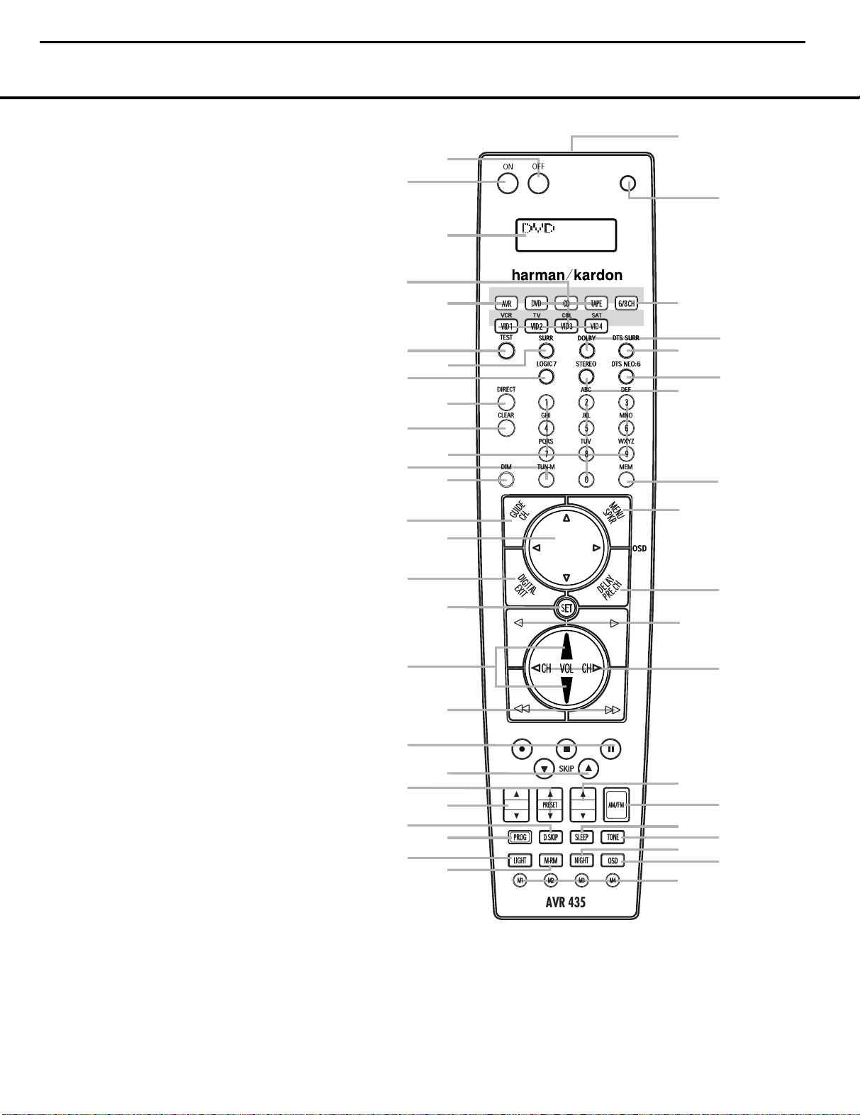
MAIN REMOTE CONTROL FUNCTIONS
0
Power Off Button
1
Power On Button
2
LCD Information Display
3
Input Selectors
4
AVR Selector
5
Test Button
6
DSP Surround Mode Selector
7
Logic 7 Mode Select Button
8
Direct Button
9
Clear Button
A
Numeric Keys
B
Tuning Mode Button
m Dim Button
n Channel Select Button
o Navigation Button
F
Digital Select Button
G
Set Button
H
Volume Up/Down Selectors
I
Transport Fast-Play/Scan Buttons
J
Main Transport Controls
K
Track Skip Up/Down Buttons
L
Preset Up/Down Button
M
Video Input Button
N
Disc Skip Button
O
Program Button
P
Light Button
Q
Multiroom Button
R
Macro Buttons
S
OSD Button
T
Night Mode Button
U
Tone Control Button
V
Sleep Button
W
AM/FM Button
X
Tuning Up/Down Button
Y
Channel Up/Down Selector
Z
Transport Play Buttons
a
Delay Select Button
b
Speaker Select Button
c Memory Button
d Stereo Mode Select Button
e DTS Neo:6 Mode Select Button
f DTS Digital Mode Select Button
g
Dolby Mode Select Button
h
6/8-Channel Input Select
i Mute Button
j Lens
NOTES:
• The function names shown here are each button’s feature when used with the AVR 435. Most
buttons have additional functions when used with other devices.When a button is pressed, the
function name will appear in the bottom line of the
• The jack on the upper right side of the remote is reserved for future use. Do not remove the
plug provided or connect any device to the jack.
• To make it easier to follow the instructions that refer to this illustration, a larger copy may be
downloaded from the Product Support section for this product at www.harmankardon.com.
LCD Information Display c.
MAIN REMOTE CONTROL FUNCTIONS 11MAIN REMOTE CONTROL FUNCTIONS 11
Page 14

40
41
37
36
50
51
47
46
38
39
40
41
37
36
35
34
33
48
49
50
51
47
46
45
44
43
AVR435/635 harman/kardon
14
MAIN REMOTE CONTROL FUNCTIONS
MAIN REMOTE CONTROL FUNCTIONS
IMPORTANT NOTE: The AVR 435’s remote may
be programmed to control up to eight devices,
including the AVR 435. Before using the remote,
it is important to remember to press the
Selector Button
3
that corresponds to the unit
Input
you wish to operate. In addition, the AVR 435’s
remote is shipped from the factory to operate the
AVR 435 and most Harman Kardon CD or DVD
players and cassette decks.The remote is also
capable of operating a wide variety of other products
using the control codes that are part of the remote.
Before using the remote with other products, follow
the instructions on pages 43 – 46 to program the
proper codes for the products in your system.
It is also important to remember that many of the
buttons on the remote take on different functions,
depending on the product selected using the
Selectors
d. The descriptions shown here primarily
Input
detail the functions of the remote when it is used to
operate the AVR 435.
a Power Off Button: Press this button to place
the AVR 435 or a selected device in the Standby
mode. Note that this will turn off the main room
functions, but if the Multiroom system is activated,
it will continue to function.
1
Power On Button: Press this button to turn on
the power to a device selected by first pressing one of
the
Input Selectors3.
2
LCD Information Display: This two-line screen
displays various information depending on the commands that have been entered into the remote.
3
Input Selectors: Pressing one of these buttons
will perform three actions at the same time. First, if the
AVR 435 is not turned on, this will power up the unit.
Next, it will select the source shown on the button as
the input to the AVR 435. Finally, it will change the
remote control so that it controls the device selected. In
normal operation, the remote will revert to controlling
the AVR when no button is pressed for 6 seconds.
This allows the remote to automatically return to control of important functions such as volume, mute and
surround mode selection after you have used the
remote to control another device. If you wish to
change the length of time that the remote operates
another device, or to have the remote remain active
for control of the other device (such as a DVD player
or set-top box) until you manually return control to the
AVR by pressing the
AVR Selector4, follow the
instructions on page 52.
4
AVR Selector: Pressing this button will switch the
remote so that it will operate the AVR 435’s functions. If
the AVR 435 is in the Standby mode, it will also turn the
AVR 435 on.
5
Test Button: Press this button to begin the
sequence used to manually calibrate the AVR 435’s
output levels. (See page 29 for more information on
calibrating the AVR 435.)
g DSP Surround Mode Selector: Press this
button to select one of the DSP surround modes, such
as VMAx, Hall 1, Hall 2 or Theater. Each press of the
button selects another mode. (See page 34 for more
information on surround modes.)
7
Logic 7 Mode Select Button: Press this button
to select from among the available Logic 7 surround
modes. (See page 34 for the available Logic 7
options.)
8
Direct Button: Press this button when the tuner
is in use to start the sequence for direct entry of a
station’s frequency. After pressing the button, simply
press the proper
Numeric Keys Ato select a
station. (See page 37 for more information on the tuner.)
9
Clear Button: When programming the remote
or using the EzSet feature, press this button to cancel
the current function. When using the remote to enter
frequencies for direct tuner access, press this button
to clear previous entries.
A
Numeric Keys: These buttons serve as a 10-
button numeric keypad to enter tuner preset positions.
They are also used to select channel numbers when
TV, Cable or SAT has been selected on the remote, or
to select track numbers on a CD, DVD or LD player,
depending on how the remote has been programmed.
These buttons are also used to enter letters and numbers when renaming devices in the LCD Information
Display. (See page 50 for more information on renam-
ing devices and keys.)
B
Tuning Mode Button: Press this button to
change the tuner mode between manual and
automatic.When the button is pressed so that
AUTO/STEREO appears in the Upper
Display Line
# and in the on-screen display, only
stations with acceptable signal quality will be tuned,
and the tuner will play FM stations in stereo, when
available. In the
Up/Down Buttons
AUTO mode, when the Tuning
4X≠are pressed, the unit
will automatically search for the next available station
with good signal strength. When this button is pressed
so that
MANUAL/MONO appears in the Upper
Display Line
press of the
# and in the on-screen display, each
Tuning Up/Down Buttons 4X
≠
will move the frequency up or down in single-step
increments.When the FM band is in use, pressing the
button so that the
MANUAL mode is activated will
enable you to tune stations with weak signals by
changing to monaural reception. (See page 37 for
more information on tuner operation.)
m Dim Button: Press this button to activate the
Dimmer function, which reduces the brightness of the
front-panel display, or turns it off entirely. Press the
button once to change the display to reduce the
brightness by 50%, and press it again within 5 seconds and the main display will go completely dark.
Note that this setting is temporary; regardless of any
changes, the display will always return to full brightness when the AVR is turned on.The blue illumination
around the
Standby/On Switch 1 will always
remain at full brightness regardless of the setting to
remind you that the AVR is still turned on.The blue
accent lighting inside the volume control will also
remain at full brightness when the panel is at 50%,
but go out when the panel lights are fully dimmed.
n Channel Select Button: This button is used to
start the process of setting the AVR 435’s output levels to
an external source. Once this button is pressed, press the
⁄/¤
on the Navigation Button o to select the
channel being adjusted, then press the Set Button q,
followed by the
⁄/¤
on the Navigation Button
o
again, to change the level setting. (See page 38 for more
information.)
o
Navigation Button: This single disc-like button is
used to navigate through the on-screen configuration
menus, to scroll through the options list and to select
choices for the various settings such as delay, speakers,
surround modes, digital inputs, etc. To use the button,
simply press it left, right, up or down in the direction
indicated by the
⁄ /¤/‹ /› icons printed on the
button disc. Depending on the menu being used,
pressing the button will either change a specific menu
or configuration choice, or it will change the option
shown in the on-screen or front-panel display.The
sections in this manual describing the unit’s individual
features and configuration options contain specific
information on how the navigation controls are used.
p
Digital Select Button: Press this button to assign
one of the digital inputs KL to a source.
(See page 33 for more information on using digital
inputs.)
q
Set Button: This button is used to enter settings
into the AVR 435’s memory. It is also used in the
setup procedures for delay time, speaker configuration
and channel output level adjustment.
H
Volume Up/Down Buttons: These controls
share the common disc in the lower third of the
remote.To raise the volume, press the button marked
⁄
by pressing towards the top of the remote.To lower
the volume, press the button marked
towards the bottom of the remote.The
¤
by pressing
‹/›
buttons
on the left and right sides of this disc change channels
up or down when the TV, cable box or satellite
Selectors
3
have been pressed.
Input
12 MAIN REMOTE CONTROL FUNCTIONS
12 MAIN REMOTE CONTROL FUNCTIONS
Page 15
AVR435/635 harman/kardon
15
MAIN REMOTE CONTROL FUNCTIONS
MAIN REMOTE CONTROL FUNCTIONS
P
s Transport Fast-Play/Scan Buttons: These but-
tons have no direct function on the AVR 435, but they
are used when the remote is programmed for a
patible DVD, CD or tape player. Pressing these buttons
will transmit a fast-play forward, fast-play reverse, or fastforward or -reverse scan command, according to the
capabilities of the player being controlled. In the factory
default setting, these buttons are preprogrammed
the remote codes for Harman Kardon DVD players
that you may control a compatible player without having to switch devices.
J
Main Transport Controls: These buttons have
no direct function on the AVR 435, but they are used
when the remote is programmed for a compatible
DVD, CD or tape player. Pressing these buttons
will transmit a stop (
command, according to the capabilities of the player
being controlled. In the factory default setting, these
buttons are programmed with the remote codes for
Harman Kardon DVD players so that you may control
a compatible player without having to switch devices.
K
Track Skip Up/Down Buttons: These buttons
do not have a direct function with the AVR 435, but
when used with a compatibly programmed CD or DVD
changer will change the track or chapter currently being
played. In the factory default setting, these buttons are
programmed with the remote codes for Harman Kardon
DVD players so that you may control a compatible player
without having to switch devices.
L
Preset Up/Down Button: When the tuner is in
use, press this button to scroll through the stations
programmed into the AVR 435’s memory.
w VDI Button: This button does not have any function for the AVR, but is provided for your use in programming the codes that are used to scroll up or
down through the available inputs on your video display.This allows you to switch video inputs that are
directly connected to your video display.Alternatively,
you may program any compatible remote code into
the “up” and “down” portions of this button. For infor-
mation on “learning” remote codes into a button
on the AVR remote, follow the instructions shown
on page 44.
N
Disc Skip Button: This button has no direct
function for the AVR 435 but may be used to change
the disc in a CD or DVD changer when the remote is
programmed for that type of device.
O
Program Button: This button is used to begin
the process of programming the remote. Press and hold
this button for 3 seconds to place the remote in the
programming mode. Once the red LED under the
Button
q
select from the desired option. (See pages 43–53 for
more information on configuring the remote.)
Í), record (Î), or pause (
lights, release the button. You may then
com-
with
so
±
)
Set
Light Button: Press this button to activate the
remote’s backlight for ease of use in darkened rooms.
Q
Multiroom Button: Press this button to begin
the process of activating the multiroom system or to
change the input or volume level for the second zone.
(See page 41 for more information on the multiroom
system.)
R
Macro Buttons: Press these buttons to store or
recall a “Macro”, which is a preprogrammed sequence
of commands stored in the remote. (See page 46 for
more information on macros.)
S
OSD Button: Press this button to activate or turn
off the On-Screen Display (OSD) system used to set up
or adjust the AVR 435’s parameters.
T
Night Mode Button: Press this button to acti-
vate the Night mode. This mode is available in specially
encoded Dolby Digital sources, and it preserves
dialogue (center channel) intelligibility at low volume
levels.
U
Tone Control Button: This button controls the
tone mode settings, enabling adjustment of the bass
and treble boost/cut. You may also use it to take the
tone controls out of the signal path completely for
“flat” response. The first press of the button displays a
TONE IN message in the Lower Display Line
$ and in the on-screen display.To take the controls
out of the signal path, press either of the
Navigation Buttons o until the display reads
TONE OUT. To change the bass or treble settings, press the button again until the desired option
appears in the
on-screen display and then press either of the
Navigation Buttons o to enter the desired boost
or cut setting. See page 32 for more information on
the tone controls.
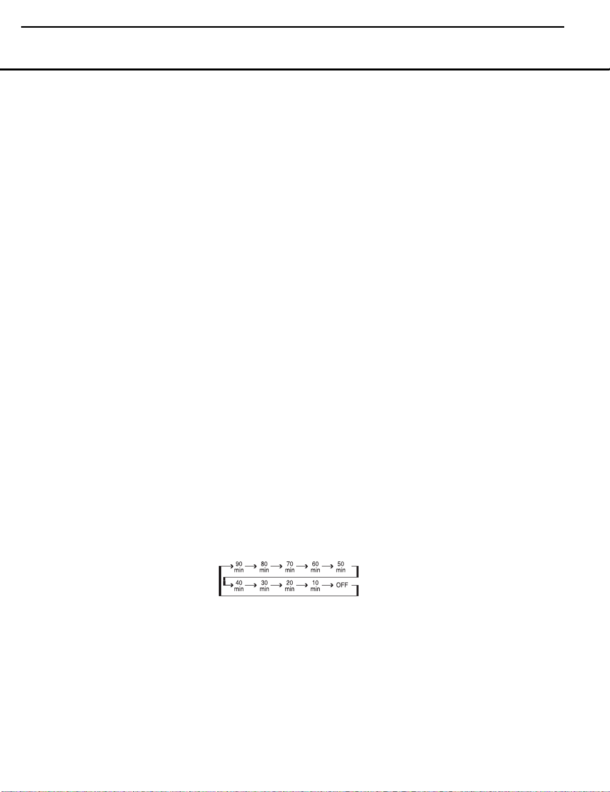
V Sleep Button: Press this button to place the unit
in the Sleep mode.After the time shown in the display,
the AVR 435 will automatically go into the Standby
mode. Each press of the button changes the time until
turn-off in the following order:
When the Sleep timer is in use, the front-panel display
indicators will dim to half brightness.
W
AVR 435’s tuner as the listening choice. Pressing this
button when the tuner is already in use will select
between the AM and FM bands.
Lower Display Line $ and in the
AM/FM Button: Press this button to select the
⁄/¤
⁄/¤
X Tuning Up/Down Button: Press this button
when the tuner is in use to change the station to one
with a higher or lower frequency.When the tuner is in
the
MANUAL/MONO mode, each tap of the
Selector will increase or decrease the frequency by
one increment. When the tuner receives a strongenough signal for adequate reception,
TUNED
$ and in the on-screen display.When the tuner is in
the
once, and the tuner will scan for a station with acceptable signal strength. When the next higher- or lowerfrequency station with a strong-enough signal is tuned,
the frequency scan will stop and the
Line
AUTO TUNED. When an FM Stereo station is
tuned, the display will read
See page 37 for more information on using the tuner.
Y
function when the AVR is being controlled, but when
programmed for use with a VCR, TV, cable box, satellite receiver or other similar product, it will change the
channel up or down. See pages 43 – 53 for more
information on programming the remote.
Z
no direct function on the AVR 435, but they are used
when the remote is programmed for a compatible
DVD, CD or tape player. Pressing these buttons will
transmit a forward- or reverse-play command,
according to the capabilities of the player being
controlled. In the factory default setting, these buttons
are programmed for Harman Kardon DVD players so
that you may control a compatible player without
having to switch devices.
a Delay Select Button: This button selects
adjustments to the A/V Sync Delay and the individual
channel displays.The first press of the button displays
an
Display Line
means that you may change the amount of time that
all channels are delayed together behind the video.
This enables you to compensate for the loss of lip
sync that may be caused by digital video processing
in your display or by television stations.To change
the A/V Sync Delay, press the
the
and then use the
to change the setting so that the sound and the
video image are in sync.To change the delay for
an individual output channel, press the
Navigation Button o until the desired channel
name is shown, and then press the
Use the
the delay amount. (See page 28 for more information
on delay options.)
will appear in the Lower Display Line
AUTO/STEREO mode, press the button
$ and the on-screen display will indicate
AUTO ST TUNED.
Channel Up/Down Selector: This button has no
Transport Play Buttons:These buttons have
A/V SYNC DELAY message in the Lower
$ and in the on-screen display, which
A/V SYNC DELAY message is visible
⁄/¤ Navigation Button o
⁄/¤ Navigation Buttons o to change
MANUAL
Lower Display
Set Button q while
⁄/¤
Set Button q.
MAIN REMOTE CONTROL FUNCTIONS 13
MAIN REMOTE CONTROL FUNCTIONS 13
Page 16

4
0
4
1
5
0
5
1
4
7
4
6
AVR435/635 harman/kardon
16
MAIN REMOTE CONTROL FUNCTIONS
b
Speaker Select Button: Press this button
to begin the process of configuring the AVR 435’s
bass management system. Then press the
⁄/¤
Navigation Button o to select the channel you
wish to set up. Press the
Set Button q and
then select another channel to configure. When all
adjustments have been completed, press the
Button
q twice to exit the settings and return to
Set
normal operation. (See page 26 for more information
on speaker setup.)
c
Memory Button: Press this button to enter a
radio station to the AVR 435’s preset memory. First,
tune the desired station, and then press this button.
Within 5 seconds of when you see the station’s
frequency flash in the
Upper Display Line # and
in the on-screen display, press the numeric keys
for the preset number between 01 and 30 that you
wish to assign to the station. (See page 37 for more
information.)
d
Stereo Mode Select Button: Press this button
to select a stereo listening mode.When the button is
pressed so that
the
Lower Display Line $, the AVR will operate
SURROUND OFF appears in
in a bypass mode with true, fully analog, two-channel
left/right stereo mode with no surround processing or
bass management, as opposed to other modes where
digital processing is used. When the button is pressed
so that
SURROUND OFF appears in the Lower
Display Line $, and the DSP and Surround
Surround Mode Indicators
% are lit, you will enjoy
Off
a two-channel presentation of the sound, along with
the benefits of bass management. Depending on
whether your system is configured for 5.1 or 6.1/7.1
channels, the next press of the button will cause either
5 CH STEREO or 7 CH STEREO to
appear, and the stereo signal will be routed to all five
(or seven) speakers. (See page 34 for more informa-
tion on stereo playback modes.)
e
DTS Neo:6 Mode Select Button: Press this
button to select a DTS Neo:6 mode. (See page 34
for the available DTS Neo:6 options.)
f
DTS Digital Mode Select Button: When a
DTS-encoded digital source is playing, each press of
this button will scroll through the available DTS modes.
The specific choice of modes will vary according to
the type of encoding on the disc and your system’s
speaker configuration. When a DTS source is not in
use, this button has no function. (See page 34 for the
available DTS digital options.)
g
Dolby Mode Select Button: This button is used
to select from the available Dolby Surround modes.
Each press of this button will select
one of the Dolby
Pro Logic II, Pro Logic IIx or Dolby Virtual Speaker
modes, as available for the number of speakers in your
system.
When a Dolby Digital-encoded source is in
use, the Dolby Digital mode may also be selected.
(See page 34 for the available Dolby surround
mode options.)
h
6-Channel/8-Channel Input Select: Press this
button to select the device connected to the
Channel Direct Inputs
. (See page 32 for more
6- or 8-
information.)
i
Mute Button: Press this button to momentarily
silence the AVR 435 or TV set being controlled,
depending on which device has been selected.
j
Lens: The infrared emitters behind the plastic
lens at the top of the remote communicate the remote
codes to the AVR 435. Be certain that the lens is not
covered when using the remote, and point the lens
toward the AVR for best results. In learning mode, the
remote receives IR codes to be learned through a
sensor behind the lens.
NOTE: DO NOT remove the rubber plug that covers the
jack on the upper right side of the remote.The jack is
not active and is reserved for future use.
14 MAIN REMOTE CONTROL FUNCTIONS
Page 17
40
41
37
36
50
51
47
46
38
39
40
41
37
36
35
34
33
48
49
50
51
47
46
45
44
43
38
39
40
41
37
36
35
34
33
32
48
49
50
51
47
46
45
44
43
42
48
49
50
51
47
46
45
44
43
42
4
1
5
1
47
38
3
9
4
0
41
48
4
9
5
0
51
47
46
45
44
39
40
41
49
50
51
4
7
46
4
5
413751
47
40
41
50
51
47
46
40
41
37
36
50
51
47
46
38
39
40
41
37
36
35
34
33
48
49
50
51
47
46
45
44
43
39
40
41
37
36
35
49
50
51
47
46
45
38
39
40
41
3
7
36
35
34
48
49
50
51
4
7
46
45
44
3
8
39
40
4
1
31
37
36
35
34
3
3
32
4
8
49
50
5
1
47
46
45
44
4
3
42
AVR435/635 harman/kardon
17
INSTALLATION AND CONNECTIONS
System Installation
After unpacking the unit, locating it in a place with adequate ventilation and placing it on a solid surface capable
of supporting its weight, you will need to make the connections to your audio and video equipment.
IMPORTANT NOTE: For your personal safety and to
avoid possible damage to your equipment and speakers,
it is always good practice to turn off and unplug the AVR
and ALL source equipment from the AC output before
making any audio or video system connections.
Audio Equipment Connections
We recommend that you use high-quality interconnect
cables when making connections to source equipment
and recorders to preserve the integrity of the signals.
1. Connect the analog output of a CD player to the
CD Audio Inputs .
NOTE: If your CD player has both fixed and variable
audio outputs, it is best to use the fixed output unless
you find that the input to the receiver is so low that the
sound is noisy, or so high that it is distorted.
2. Connect the analog Play/Out jacks of a cassette
deck, MD, CD-R or other audio recorder to the
Tape Inputs . Connect the analog Record/In
jacks on the recorder to the
on the AVR 435.
3. Connect the output of any digital sources such as
a CD or DVD changer or player, advanced video
game, a digital satellite receiver, HDTV tuner or
digital cable set-top box or the output of a compatible computer sound card to the
Coaxial Digital Audio Inputs KL.
4. Connect the coaxial or optical
ik on the rear panel of the AVR 435 to the match-
ing digital input connections on a CD-R or MiniDisc
recorder.
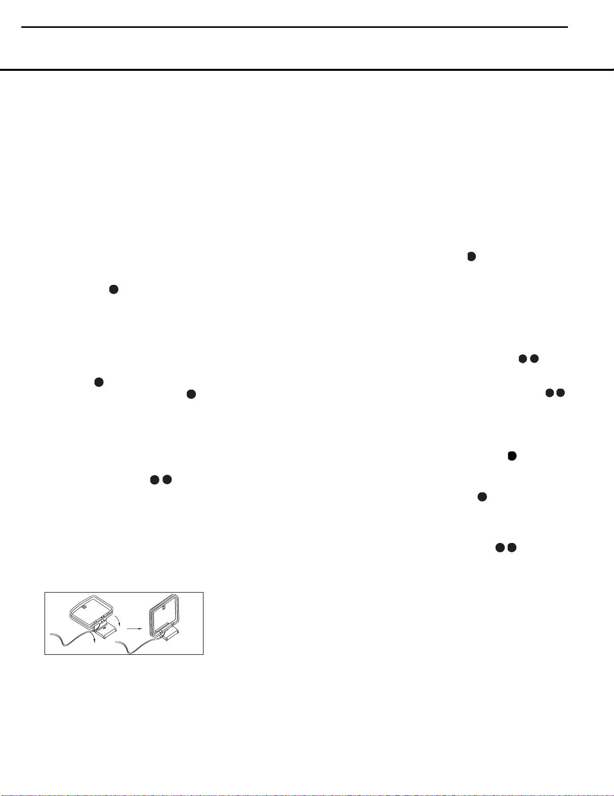
5. Assemble the AM loop antenna supplied with the unit
so that the tabs at the bottom of the antenna loop
snap into the holes in the base. Connect it to the
and GND Screw Terminals ¡ .
6. Connect the supplied FM antenna to the
Ohm
) Connection ™. The FM antenna may be
an external roof antenna, an inside powered or
wire-lead antenna or a connection from a cable
TV system. If the antenna or connection uses
300-ohm twin-lead cable, you must use an optional
16 INSTALLATION AND CONNECTIONS
Tape Outputs
Optical and
Digital Audio Outputs
FM (75-
AM
300-ohm-to-75-ohm adaptor to make the
connection.
7. Connect the front, center, surround and surround
back speaker outputs
§¶ª‚ to the respec-
tive speakers.
To ensure that all the audio signals are carried to your
speakers without loss of clarity or resolution, we suggest that you use high-quality speaker cable. Many
brands of cable are available and the choice of cable
may be influenced by the distance between your
speakers and the receiver, the type of speakers you
use, personal preferences and other factors. Your
dealer or installer is a valuable resource to consult in
selecting the proper cable.
Regardless of the brand of cable selected, we recommend that you use cable
with a gauge of 14 or smaller.
Remember that in specifying cable, the lower the
number, the thicker the cable.
Cable with a gauge of 16 may be used for short runs
of less than 10 feet. We do not recommend that you
use cables with an AWG equivalent of 18 or higher,
due to the power loss and degradation in performance
that will occur.
Cables that are run inside walls should have the appropriate markings to indicate listing with UL, CSA or other
appropriate testing agency standards. Questions about
running cables inside walls should be referred to your
installer or a licensed electrician who is familiar with
the NEC and/or the applicable building codes in
your area.
When connecting wires to the speakers, be certain
to observe proper polarity. Note that the positive (+)
terminal of each speaker connection has a specific color
code, as noted on page 8. However, most speakers
still use a red terminal for the positive (+) connection.
Connect the “negative” or “black” wire to the same
terminal on both the receiver and the speaker.
NOTE: While most speaker manufacturers adhere to
an industry convention of using black terminals for
negative and red ones for positive, some may vary
from this configuration. To ensure proper phase and
optimal performance, consult the identification plate on
your speaker or the speaker’s manual to verify polarity.
If you do not know the polarity of your speaker, ask
your dealer for advice before proceeding, or consult
the speaker’s manufacturer.
We also recommend that the length of cable used
to connect speaker pairs be identical. For example,
use the same length piece of cable to connect the
front-left and front-right or surround-left and surround-right speakers, even if the speakers are a
different distance from the AVR 435.
8. Connections to a subwoofer are normally made via
a line-level audio connection from the
Output
¢ to the line-level input of a subwoofer
Subwoofer
with a built-in amplifier. When a passive subwoofer
is used, the connection first goes to a power amplifier, which will be connected to one or more subwoofer speakers. If you are using a powered subwoofer that does not have line-level input connections, follow the instructions furnished with the
speaker for connection information.
9. If an external multichannel audio source with
5.1 outputs such as an external digital processor/
decoder, DVD-Audio or SACD player is used, connect the outputs of that device to the
Direct Inputs
.
8-Channel
Video Equipment Connections
Video equipment is connected in the same manner
as audio components.Again, the use of high-quality
interconnect cables is recommended to preserve
signal quality.
1. Connect a VCR’s or other video source’s audio and
video Play/Out jacks to the
and Video Input Jacks
Video 1/Video 2 Audio
fl° on the rear
panel. The Audio and Video Record/In jacks on the
VCR should be connected to the
Audio and Video Output Jacks
Video 1/Video 2
‡· on
the AVR 435.
2. Connect the analog audio and video outputs of a
satellite receiver, cable TV converter or television set
or any other video source to the
and Video Input Jacks
Video 3 Audio
a .
3. Connect the analog audio and video outputs of a
DVD or laser disc player to the
Video Inputs
fi .
DVD Audio and
4. Connect the optical or coaxial digital audio outputs
of a DVD player, satellite receiver, cable box, HDTV
tuner or video game to any of the
Optical or
Coaxial Digital Inputs KL. The recom-
mended connection for a DVD player is to use a
coaxial digital link connected to the Coaxial Digital
Audio Input 1, but you may change the digital
audio input assignment for any source using the
INPUT SETUP menu, as described on page
21 or the
Digital Input Selector Fp on the
front panel or remote (see page 33).
NOTE: When connecting a device such as a digital
cable box or other set-top tuner product with a digital
audio output, we recommend that you connect both
the digital and analog outputs of the product to your
AVR. The audio input polling feature of the AVR will
then be able to make certain that you have a constant
audio feed, since it will automatically switch the audio
input to the analog jacks if the digital feed is interrupted
or not available for a particular channel.
Page 18

40
41
37
36
50
51
47
46
38
39
40
41
37
36
35
34
33
48
49
50
51
47
46
45
44
43
48
49
50
51
47
46
45
44
43
42
39
40
41
49
50
51
47
46
45
41
37
51
47
4
0
41
3
7
3
6
5
0
51
4
7
4
6
38
3
9
4
0
41
3
7
3
6
3
5
3
4
33
3
2
48
4
9
5
0
51
4
7
4
6
4
5
4
4
43
4
2
AVR435/635 harman/kardon
18
INSTALLATION AND CONNECTIONS
If your system requires direct connection of a video
source to your display, we suggest that you consider
programming the
VDI Buttons w so that you may
change the input used by your display from the AVR’s
remote. For information on “learning” remote codes
into a button on the AVR remote, follow the instruc-
tions shown on page 44.
5. Connect the
Video Monitor Output Jacks › on
the receiver to the composite or S-video input of
your television monitor or video projector.
6. If your DVD player has Y/Pr/Pb analog component
video outputs, connect them to the
Video 1 Inputs
c. Although this set of inputs may
Component
be assigned to any of the four video inputs on
the AVR 435, the factory default is for this input
to be assigned to the
DVD Audio Inputs .
Remember to make a digital audio connection
between the DVD player and the AVR, with the
Coaxial Digital Input 1 being the factory
default. For information on changing the input
assignments for either the component video
jacks or the DVD player’s audio connection, see
page 21.
7. If you have other devices with Y/Pr/Pb or RGB
component video outputs, connect the source
device to the
The audio connections may be to any of the
Audio Inputs
Component Video 2 Inputs d.
Video
M or the Optical or
Coaxial Digital Inputs KL. When using
either of the Component Video Inputs, make certain
that the audio and video inputs are properly configured in the
INPUT SETUP menu, as
described on page 21.
8. If the component video inputs are used, connect
the
Component Video Monitor Outputs b to
the component video inputs of your TV, projector
or display device.
9. If you have a camcorder, video game or other
audio/video device that is connected to the AVR on
a temporary rather than permanent basis, connect
the audio, video and digital audio outputs of that
device to
the Front-Panel Inputs KLM. A
device connected
here is selected as the Video 4
input, and the digital inputs must be assigned to the
Video 4 input. (See page 21 for more information
on input configuration.)
System and Power Connections
The AVR 435 is designed for flexible use with multiroom systems, external control components and
power amplifiers.
Main Room Remote Control Extension
If the receiver is placed behind a solid or smoked
glass cabinet door, the obstruction may prevent the
remote sensor from receiving commands. In this
event, an optional remote sensor may be used.
Connect the output of the remote sensor to the
Remote IR Input Jack g.
If other components are also prevented from receiving
remote commands, only one sensor is needed. Simply
use this unit’s sensor or a remote eye by running a
connection from the
Remote IR Output Jack h to
the Remote IR Input jack on Harman Kardon or other
compatible equipment.
Multiroom IR Link
The remote room IR receiver should be connected to
the AVR 435 via standard coaxial cable. Plug the IR connection cable into the
Multiroom IR Input Jack f on
the AVR 435’s rear panel.
If other Harman Kardon-compatible source equipment
is part of the main room installation, the
Remote IR
Output Jack h on the rear panel should be con-
nected
to the IR IN jack on source equipment. This will
enable the remote room location to control source
equipment functions.
When a remote IR sensor is used to control nonHarman Kardon source equipment, we recommend
that you make a direct connection or use an optional,
external IR “blaster” connected to the
Carrier Output Jack
i. If you are in doubt as to
Remote IR
which IR Output jack to use for the equipment in your
system, contact your dealer or installer, or the manufacturer’s support site and ask whether the unit to be
controlled uses “full carrier” or “stripped” carrier IR
commands.When “full carrier commands” are used,
make the connection to the
Output Jack
the
Remote IR Output Jack h as noted above.
i. Otherwise, make the connection to
Remote IR Carrier
NOTE: All remotely controlled components must be
linked together in a “daisy chain.” Connect the
IR OUT
jack of one unit to the IR IN of the next to establish
this chain.
Multiroom Connections
The AVR 435 is equipped with multizone capabilities
that allow it to send a separate audio source to the
remote zone from the one selected for use in the
main room.
Depending on your system’s requirement, three
options are available for audio connection:
Option 1: Use high-quality, shielded audio interconnect cable from the AVR 435’s location to the remote
room. In the remote room, connect the interconnect
cable to a stereo power amplifier. The amplifier will be
connected to the room’s speakers.At the AVR 435,
plug the audio interconnect cables into the
Audio Outputs
j on the AVR 435’s rear panel.
Multiroom
INSTALLATION AND CONNECTIONS 17
Option 2: Connect the Multiroom Audio Outputs
j on the AVR 435 to the inputs of an optional stereo
power amplifier. Run high-quality speaker wire from
the amplifier to the speakers in the remote room.
Option 3: Taking advantage of the AVR 435’s built-in
seven-channel amplifier, it is possible to use two of the
amplifier channels to power speakers in the remote
room. When using this option, you will not be able to
use the full 7.1-channel capabilities of the AVR 435 in
the main listening room, but you will be able to add
another listening room without external power amplifiers.To use the internal amplifiers to power a remote
zone, connect the speakers for the remote room location to the
Outputs
Surround Back/Multiroom Speaker
‚. Before using the remote room, you
will need to configure the amplifiers for surround operation by changing a setting in the
MULTIROOM
menu, following the instructions shown on page 41.
NOTE: For all options, you may connect an optional
IR sensor in the remote room to the AVR 435 via an
appropriate cable. Connect the sensor’s cable to the
Multiroom IR Input f on the AVR 435 and use
the Zone II remote to control the room volume. Alternatively, you may install an optional volume control
between the output of the amplifiers and the speakers.
A-BUS®Installation Connections
The AVR 435 is among the few receivers available
that offer built-in A-BUS Ready operation. When used
with an optional A-BUS product, you have all the benefits of remote zone operation without the need for an
external power amplifier.
To use the AVR 435 with an approved A-BUS product, simply connect it to the AVR 435 using standard
Category 5 wiring that is properly rated for the specific
in-wall installation. Terminate the wiring at the receiver
end to a standard RJ-45 connector in compliance
with the instructions furnished with the A-BUS product.
You may connect a single A-BUS module to the
AVR 435 with no further equipment needed. If you
wish to connect more than one A-BUS module, an
optional, external A-BUS hub may be used to
provide that capability. Contact your dealer or
www.harmankardon.com for more information on
other A-BUS products available from Harman Kardon.
No further installation or adjustment is needed, as the
A-BUS jack on the AVR 435 routes the signals to their
proper destination for power, signal source and control.
The output fed to the A-BUS jack is determined by the
AVR 435’s multiroom system and menus.
RS-232 Connections
The AVR 435 is equipped with an RS-232 Serial
Connection Port
e that may be used for two pur-
poses.When the port is connected to a compatible,
Page 19

AVR435/635 harman/kardon
19
INSTALLATION AND CONNECTIONS
optional, external computer, keypad or control system,
the AVR 435 is capable of bi-directional communications that enable the external system to control the
AVR, and for the AVR to report status and handshake
data back to the controller. Use of the RS-232 port for
this type of control requires specific technical knowledge, and we recommend that any connection and
programming for control be made by a trained installer
or technician familiar with the equipment being used.
The RS-232 port may also be used as an access
point through which the AVR 435’s operating system
and surround mode memories may be updated via
connection to a compatible computer. At the time
that any upgrade is available, instructions for making
the connection and installing the upgrade will be
available through the Product Support area of the
Harman Kardon Web site at harmankardon.com.
The physical connection to the AVR 435’s RS-232
port is a standard D-SUB 9 connection, but to ensure
compatible and proper operation, specific software
commands and pin wiring schemes may be required.
AC Power Connections
This unit is equipped with two accessory AC outlets.
They may be used to power accessory devices, but
they should not be used with high-current draw equipment such as power amplifiers.The total power draw
to each outlet may not exceed 100 watts.
The
Switched AC Accessory Outlet ⁄ is powered
only when the unit is on. This is recommended for
devices that have a mechanical power switch that may
be left in the “ON” position.
NOTE: Many audio and video products go into a
Standby mode when they are used with switched outlets.This type of product may not operate properly
when used with the switched outlet.
The
Unswitched AC Accessory Outlet ¤ is
powered as long as the AVR is plugged into a
powered AC outlet.
The AVR 435 features a removable power cord
that allows wires to be run in advance to a complex
installation so that the unit itself need not be installed
until it is ready for connection. When all needed
connections have been made, connect the AC
Power cord to the
The AVR 435 draws significantly more current than
other household devices, such as computers, that use
removable power cords. For that reason, it is important
that only the cord supplied with the unit (or a direct
replacement of identical capacity) be used.
Once the power cord is connected, you are almost
ready to enjoy the AVR 435’s incredible power
and fidelity!
AC Power Cord Jack ‹.
18 INSTALLATION AND CONNECTIONS
18 INSTALLATION AND CONNECTIONS
Page 20
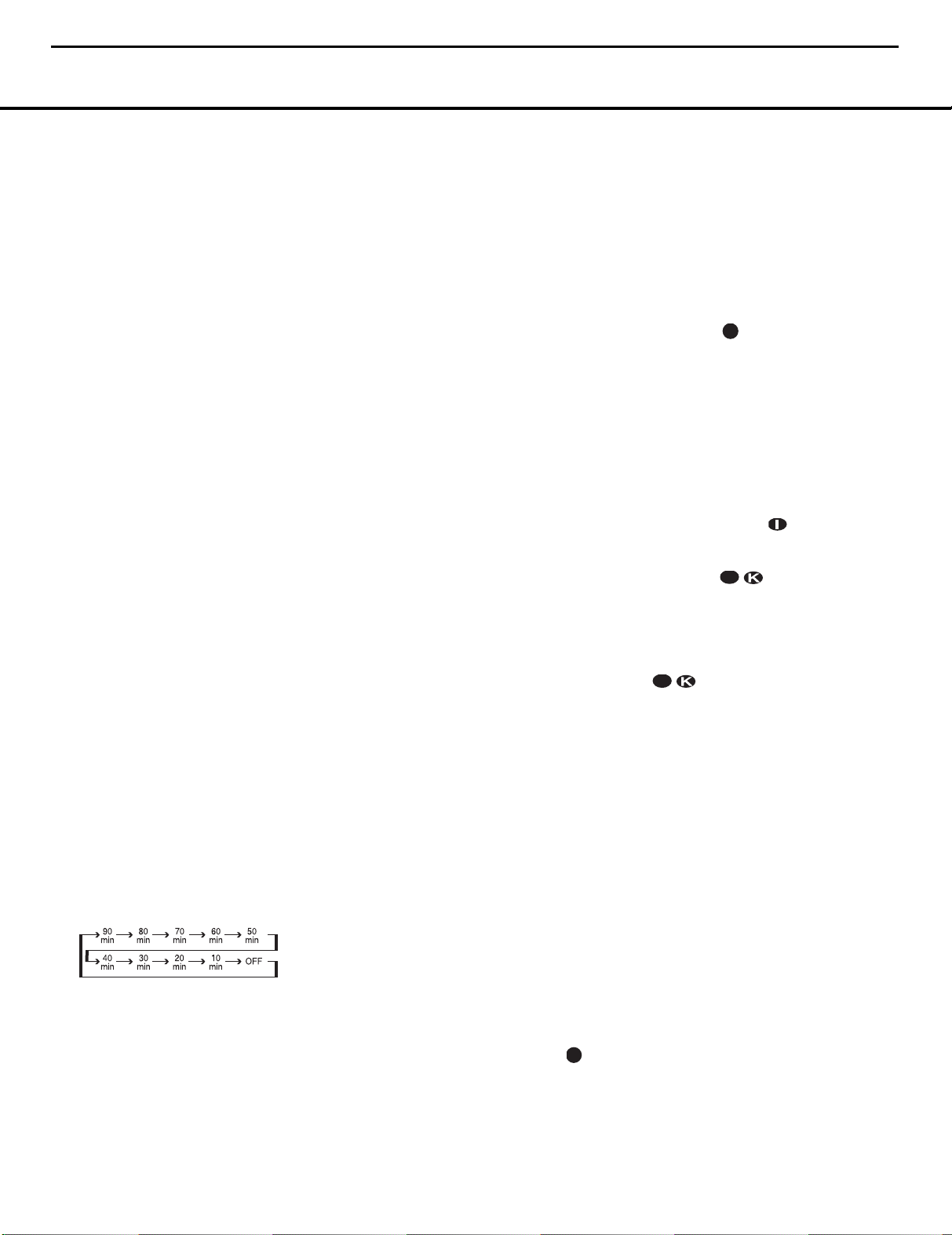
33
34353637383940
41
48494647444542
43
40
41
37
36
50
51
47
46
33
34353637383940
41
48494647444542
43
40
41
26
37
37
36
50
51
47
46
40
41
50
51
47
46
40
41
50
51
47
46
AVR435/635 harman/kardon
20
OPERATION
Basic Operation
Once you have completed the initial setup and configuration of the AVR 435, it is simple to operate and
enjoy.The following instructions will help you maximize
the enjoyment of your new receiver:
Turning the AVR 435 On or Off
• When using the AVR 435 for the first time, you must
press the
This places the unit in a Standby mode, as indicated by
the amber illumination surrounding the
Switch
a listening session by pressing the
1
on the front panel, or the Power On Button b or
AVR Selector e∫on the remote.This will turn
the unit on and return the AVR to the input source that
was last used. The unit may also be turned on from
Standby by pressing any of the
Buttons
Input Source Selector Button7on the front panel.
Whenever the AVR is turned on, you will see all of the
front-panel indicators light up for a few seconds.This is
normal, and it is part of the unit’s power-on self test
procedure.
NOTE: After pressing one of the Input Selector
Buttons
press the
control to the AVR 435 functions.
To turn the unit off at the end of a listening session,
simply press the
panel or the
remote. Power will be shut off to any equipment
plugged into the rear-panel
Outlet
On Switch
When the remote is used to turn the unit “off,” it is
actually placing the system in a Standby mode, as indicated by the amber lighting around the
Switch
• To program the AVR 435 for automatic turn-off,
press the
press of the button will decrease the time before
shut-down in the following sequence:
Once you have set the desired Sleep Time, the front
panel display will automatically dim to half brightness
and return. To check on the time remaining until the
unit shuts off, press the
To cancel the Sleep function,
Sleep ButtonS until the information display returns
to normal brightness; and the words
OFF
32 OPERATION
Main Power SwitchAto turn the unit on.
Standby/On
1
. Once the unit is in Standby, you may begin
Standby/On Switch
Input Selector
dXh
dXh
AVR Selector e∫to set the remote
⁄ and the illumination around the Standby/
1 will turn amber.
1.
will appear in the Lower Display Line $
ç∂
Standby/On Switch 1 on the front
Power Off Button aåon the
Sleep Button Son the remote. Each
on the remote or the
ç∂
to turn the unit on,
Switched AC Accessory
Standby/On
Sleep Button S once.
press and hold the
SLEEP
When you will be away from home for an extended
period of time, it is always a good idea to completely
turn the unit off with the front-panel
A
Switch
NOTE: All preset memories are lost if the unit is left
turned off by using the
more than four weeks.
.
Main Power SwitchAfor
Main Power
Source Selection
• To select a source, press any of the Input Selector
Buttons
dXh
• The input source may also be changed by pressing
the front-panel
Each press of the button will move the input selection through the list of available inputs.
• When a new input is selected, the AVR will automat-
ically switch to the digital input (if selected), surround
mode, component video input, A/V Sync Delay and
Night Mode configurations that were in effect the
last time that input was used. If the
TRIM
line on the CHANNEL ADJUST
menu (Fig. 20) was set to INDEPENDENT,
as shown on pages 30–31, the settings for channel
output levels will also change to the preset values.
• The front-panel
K
3 Input
be used to connect a device such as a video game
or camcorder to your home entertainment system on
a temporary basis.
• As the input source is changed, the new input name
will appear momentarily as an on-screen display in
the lower third of the video display.The input name
will also appear in the
in the front-panel
• When an audio only source is selected, the last video
input used remains routed to the
Video Outputs
›. This permits simultaneous viewing and listening
to different sources.
• When a composite or S-video source is selected, the
video signal for that input will be routed to the
Monitor Output
monitor connected to the AVR 435.
6-Channel/8-Channel Direct Input
There are two input choices available for use with
sources such as a DVD-Audio or SACD player that are
connected to the
Select the appropriate input according to the way your
system and source equipment is configured:
.
or the Coaxial Digital 3 Input Lmay
ç∂
Input Source Selector Button 7.
Video 4 InputsM, Optical Digital
Upper Display Line # and
Input Indicators !.
‡· and Video Monitor Outputs
›
and will be viewable on a TV
8-Channel Direct Inputs .
on the remote.
LEVEL
Video 1/Video 2
Video
• The
6 CH DIRECT input should be used
when the SBR and SBL inputs are NOT in use and
the input source device has its own internal bass
management system. This input passes the input
from the source directly through to the volume control without any analog to digital conversion and it
mutes the unused input jacks to prevent unwanted
noise from interfering with system performance.
• The
8 CH DIRECT input should be used
when an input is connected to all eight
Direct Inputs
device has its own internal bass management system. This input passes the input from the source
directly through to the volume control without any
analog to digital conversion and it mutes the
unused input jacks to prevent unwanted noise
from interfering with system performance.
and when the input source
8-Channel
Volume and Tone Control
• Adjust the volume to a comfortable level using the
front-panel
Up/Down Buttons
• To temporarily silence all speaker outputs, press the
Mute Button . This will interrupt the output to all speakers and the headphone jack, but it
will not affect any recording or dubbing that may be
in progress.When the system is muted, the word
MUTE will flash in the on-screen display and
Upper Display Line #, press the Mute Buttons
• The unit’s tone controls may be taken out of the
signal path by pressing the
the front panel
press of either button will show a message in the
on-screen display and
with the current status of the tone controls.The system default is
the bass and treble controls are active. Press the
⁄/¤ Navigation Button o on the remote or
the
the setting to
response without the tone controls being active.
• When the tone controls are active, the amount of
bass and treble boost/cut may be adjusted by first
pressing the
C or the remote V two or three times until the
desired setting (
MODE
Lower Display Line $. Next, use the ⁄/¤
Navigation Button o on the remote or the ‹/›
Button on the front panel H to change the setting
as desired. The unit will return to normal operation
within 5 seconds after the setting is changed.
Volume Control ) or remote Volume
r .
again to return to normal operation.
Tone Mode Button on
C or the remote V. The first
Lower Display Line $
TONE IN, which indicates that
‹/› Button H on the front panel to change
TONE OUT, which is “flat”
Tone Mode Button on the front panel
BASS MODE or TREBLE
) appears in the on-screen display and the
Page 21

40
41
37
36
50
51
47
46
38
39
40
41
37
36
35
34
33
48
49
50
51
47
46
45
44
43
40
41
42
43
41
37
51
47
AVR435/635 harman/kardon
21
OPERATION
• For private listening, simply place a standard
1/4" stereo headphone plug or adaptor into the
Headphone Jack B behind the door 9 on the
front panel. The speakers will automatically mute
and a two-channel stereo signal will be sent to the
headphones.The
Lower Display Line $ will read
DOLBY H: BP, indicating that the headphone
output is in the Bypass mode, and to confirm that
no processing is being used.
• When the headphones are in use, you may take
advantage of the Dolby Headphone modes to bring
added spaciousness to headphone listening. Press
the
Dolby Mode Select Button g or the
Surround Mode Selector 3 to cycle through the
three Dolby Headphone modes to select the one
that you prefer.
Surround Mode Selection
One of the most important features of the AVR 435
is its ability to reproduce a full multichannel surround
sound field from digital sources, analog matrix
surround-encoded programs and standard stereo
programs.
Selection of a surround mode is based on personal
taste, as well as the type of program source material
being used. For example, motion pictures or TV programs bearing the logo of one of the major surroundencoding processes, such as Dolby Surround or DTS
Stereo may be played in either the Dolby Digital,
Dolby Pro Logic II Cinema, DTS Neo:6 Cinema, or
Logic 7 Cinema surround modes, depending on the
source material.
NOTE: Once a program has been encoded with matrix
surround information, it retains the surround information
as long as the program is broadcast in stereo.Thus,
movies with surround sound may be decoded via any
of the analog surround modes such as Pro Logic II
Cinema, Logic 7 Cinema or DTS Neo:6 Cinema, when
they are broadcast via conventional TV stations, cable,
pay-TV and satellite transmission. In addition, a growing
number of made-for-television programs, sports broadcasts, radio dramas and music CDs are also produced
in surround sound. You may view a list of these programs at the Dolby Laboratories Web site at
www.dolby.com.
Even when a program is not listed as carrying intentional
surround information, you may find that the Pro Logic II,
Pro Logic IIx, Logic 7 or DTS Neo:6, and the Hall or
Theater modes often deliver enveloping surround presentations through the use of the natural information
present in all stereo recordings.
Surround modes may be changed at any time by
using either the front panel or remote control. To
select a new surround mode from the front panel, first
press the
Surround Mode Group Selector Button
2 until the desired major surround mode group such
as Dolby, DTS or Logic 7 is selected. Next, press the
Surround Mode Selector Button 3 to choose the
specific individual surround mode.
To select a surround mode using the remote, press
the button for the major surround mode group that
includes the mode you wish to choose from:
Dolby
g, DTS Digital f, DTS Neo:6 e, Logic 7
h, Stereo d or DSP Surround g. The first
press of the button will show the current mode from
that group if it is already in use, or the first available
mode if you are currently using another mode.To
cycle through the available modes in that group,
press the button again until the desired mode appears
in the
Lower Display Line $ and the on-screen
display and in the front-panel
Indicators
%.
Surround Mode
The Dolby Digital, Dolby Digital EX, DTS 5.1, DTS-ES
Matrix and DTS-ES Discrete modes may only be
selected when a digital input is in use. In addition,
when a digital source is present, the AVR 435 will
automatically select and switch to the correct mode,
regardless of the mode that has been previously
selected. For more information on selecting digital
sources, see the Digital Audio Playback section below.
When the 6-Channel/8-Channel direct inputs are in
use, there is no surround processing, as these inputs
take the analog output signals from an optional, external DVD-Audio or SACD player, or another source
device and carry them straight through to the volume
control without any further digital processing.
To listen to a program in traditional two-channel
stereo, using the front left and front right speakers
only (plus the subwoofer, if installed and configured),
press the
Stereo Mode Select Button until
SURROUND
Line
$. From the front panel, press the Surround
Mode Group Selector
appear in the on-screen display and
Line
$. Next, press the Surround Mode Selector
Button
3 until SURROUND OFF appears in
the on-screen display and
OFF appears in the Lower Display
2 until the Stereo
modes
Lower Display
Lower Display Line $.
Digital Audio Playback
Digital audio is a major advancement over older analog
surround processing systems. It delivers up to six discrete channels, and each channel reproduces full frequency range (20Hz to 20kHz) and offers dramatically
improved dynamic range and significant improvements to
signal-to-noise ratios. In addition, digital systems have the
capability to deliver an additional channel that is specifically devoted to low-frequency information. This is the
“.1” channel referred to when you see these systems
described as “5.1,” “6.1” or “7.1.” The bass channel is
separate from the other channels, but since it is intentionally bandwidth-limited, sound designers have given it
that unique designation. When a Digital soundtrack is
playing, the number of channels available will vary
according to the way in which the program was
recorded. Although most movies recorded with digital
sound have 5.1 soundtracks, some have 6.1 or 7.1
sound, while others retain the original 2.0 or even
monaural sound. When the program source is a
broadcast, cable or satellite delivered digital program,
only one type of soundtrack may be delivered at a
time, while optical sources such as DVD may provide
more than one audio option. In either case, the decision of what type of sound track and how many channels to offer is up to the program’s producer. With the
AVR 435 you are able to not only play back the original compatible digital format, but using the processing
power of the Texas Instruments DSP processor it is
possible to decode the basic digital track for 2.0 or
5.1 sound and then select an additional “post-processing” mode to deliver additional channels.
Dolby Digital
Dolby Digital is a standard part of DVD, and is available
on specially encoded LD discs and satellite broadcasts and it is a part of the high-definition television
(HDTV) system.
An optional, external RF demodulator is required to
use the AVR 435 to listen to the Dolby Digital soundtracks available on laser discs. Connect the RF output
of the LD player to the demodulator and then connect
the digital output of the demodulator to the
Optical or
Coaxial Inputs KM of the AVR 435. No
demodulator is required for use with DVD players or
DTS-encoded laser discs.
In order to provide maximum playback compatibility
with DVDs, the AVR 435 receiver will always default
first to the playback mode embedded in a disc’s digital
“flag” information. For Dolby Digital discs, the following
playback modes are initially selected after the AVR
locks to the incoming digital audio data stream to
identify the selected:
• When a 5.1 audio stream is detected, the Dolby
Digital 5.1 format will be selected, regardless of the
number of speakers in your system, in compliance
with Dolby Laboratories licensing requirements.
• When a disc with the Dolby Digital EX format flag is
played, your system will automatically switch to the
EX mode when seven main channel speakers are
available.
Continued on page 35
OPERATION 33
Page 22

3
8
39
40
4
1
37
3
6
3
5
3
4
33
32
4
8
49
50
5
1
47
4
6
4
5
4
4
43
42
4
0
4
1
37
3
6
5
0
5
1
47
4
6
38
39
40
4
1
3
7
36
35
34
3
3
48
49
50
5
1
4
7
46
45
44
4
3
40
41
37
36
50
51
47
46
38
39
40
41
37
36
35
34
33
48
49
50
51
47
46
45
44
43
AVR435/635 harman/kardon
22
OPERATION
• When a disc with Dolby Digital data, but only
2.0 audio is detected, the default mode is Dolby
Digital with Pro Logic II post-processing when you
have a 5.1 speaker system, or Dolby Digital with
Pro Logic IIx post-processing when you have
a 7.1 speaker system.
• Depending on the number of speaker channels
available in your system, once the AVR locks to
the digital signal, you may select any surround
mode or post-processing option that is available,
based on the incoming data stream’s possible
restrictions and the number of speakers in your
system. For example, when a 5.1 or 2.0 audio
stream is in use, you may select alternate postprocessing such as Logic 7/7-Channel Movie
Mode post-processing to create the rear surrounds
in 7.1 speaker systems.
DTS
DTS is another digital audio system that is capable of
delivering 5.1 or 6.1 discrete or matrix sound field
reproduction. Although both DTS and Dolby Digital are
digital, they use different methods of encoding the signals, and thus they require different decoding circuits
to convert the digital signals back to analog.
DTS-encoded soundtracks are available on select DVD
and LD discs, as well as on special audio-only DTS
discs.You may use any LD or CD player equipped
with a digital output to play DTS-encoded discs with
the AVR 435.All that is required is to connect the
player’s output to either an
Optical or Coaxial Input
on the rear panel or front panel KM.
In order to listen to DVDs encoded with DTS soundtracks, the DVD player must be compatible with the
DTS signal, which is indicated by a DTS logo on the
player’s front panel. Early DVD players may not be
able to play DTS-encoded DVDs.This does not indicate a problem with the AVR 435, as some players
cannot pass the DTS signal through to the digital outputs. If you are in doubt as to the capability of your
DVD player to handle DTS discs, consult the player’s
owner’s manual.
NOTE: Some DVD players have a default setting that
does not pass through the DTS signal. Before playing
DVDs with a DTS soundtrack, make certain that the
settings in your DVD player have been properly adjusted
so that DTS audio is passed through. Consult the
owner’s manual for your DVD player for more information on making these settings.
Selecting a Digital Source
To utilize either digital mode, you must have properly
connected a digital source to the AVR 435. Connect
the digital outputs from DVD players, HDTV receivers,
satellite systems or CD players to the
Optical or
Coaxial Inputs KM . In order to provide a
backup signal and a source for analog stereo recording,
the analog outputs provided on digital source equipment
should also be connected to their appropriate inputs on
the AVR 435 rear panel (e.g., connect the analog stereo
audio output from a DVD to the
DVD Audio Inputs
on the rear panel when you connect the source’s
digital outputs).
If you have not already configured an input for a digital
source using the on-screen menus as shown on page
21, first select the input using the remote or front
panel controls, as outlined in this manual. Next,
select the digital source by pressing the
Select Button
pF and then using the ⁄/
Navigation Button o on the remote or the‹/
Button H on the front panel to
OPTICAL or COAXIAL
appear in the
Upper Display Line # or on-screen
Digital
¤
›
choose any of the
inputs, as they
display.When the digital source is playing, the
AVR 435 will automatically detect which type of digital
data stream is being decoded and display that information in the
Upper Display Line #.
When both a digital and an analog connection are
made between a source device and the AVR, the digital input is the default. If the digital stream is not present or is interrupted, the unit will automatically switch
over to the analog inputs for the selected source.
If you wish to disable the auto-polling feature, you
may do so by following the instructions shown in the
Advanced Features section of this manual on page 40.
Digital Bitstream and Surround Mode Indications
When a digital source is playing, the AVR 435 senses
the type of bitstream data that is present. Using this
information, the correct surround mode will automatically be selected. For example, DTS bitstreams will
cause the unit to switch to DTS decoding, and Dolby
Digital bitstreams will enable Dolby Digital decoding.
When the unit senses PCM data from CDs or LDs, you
may select any of the standard Dolby or DTS surround
modes or Logic 7. Since the range of available surround modes is dependent on the type of digital data
that is present, the AVR 435 shows you what type of
signal is present to help you understand the choice of
modes.
When a digital source is first detected, the AVR 435
will display a message to indicate the type of bitstream
being received. This message will appear shortly after
an input or surround mode is changed, and will remain
in the
Lower Display Line $ for about five seconds
before that portion of the display returns to the normal
surround mode indication.
For Dolby Digital and DTS sources, a numerical indication (such as 3/2/2.1) will appear, showing the number of channels present in the data.
The first number in the display message indicates how
many discrete front-channel signals are present.
• A “3” tells you that separate front left, center and
front right signals are available.This will be displayed
for Dolby Digital 5.1 and DTS 5.1 programs.
• A “2” tells you that separate front left and right signals are available, but there is no discrete center
channel signal. This will be displayed for Dolby
Digital bitstreams that have stereo program material.
• A “1” tells you that there is only a mono channel
available in the Dolby Digital bitstream.
The middle number in the display message indicates
how many discrete surround channel signals are present.
• A "3" tells you that separate, discrete left surround,
center surround and right surround signals are present. This is available only on discs with DTS-ES
digital audio.
• A “2” tells you that separate surround left and right
signals are available.This will be displayed for Dolby
Digital 5.1 and DTS 5.1 programs.
• A “1” tells you that there is only a single, surroundencoded surround channel. This will appear for
Dolby Digital bitstreams that have matrix encoding.
• A “0” indicates that there is no surround channel
information. This will be displayed for two-channel
stereo programs.
The last number indicates whether there is a discrete
low-frequency effects (LFE) channel. This is the “.1” in
the common abbreviation of “5.1” sound and it is a
special channel that contains only bass frequencies.
• A “.1” tells you that an LFE channel is present. This
will be displayed for Dolby Digital 5.1 and DTS 5.1
programs, as available.
• A “0” indicates that there is no LFE channel information available. However, even when there is no
dedicated LFE channel, low-frequency sound will be
present at the subwoofer output when the speaker
configuration is set to show the presence of a
subwoofer.
• The information in the right side of the display will
tell you if the digital audio data contains a special
flag signal that will automatically activate the appropriate 6.1 or 7.1 mode.This will be shown as
EX-ON or EX-OFF for Dolby Digital bitstreams and
ES-ON or ES-OFF for DTS bitstreams.
When a 2.0 or 5.1 digital source is playing on a system configured for 5.1operation, you may use Dolby
Digital EX, DTS-ES, Logic 7/7 or Dolby Pro Logic IIx
to add rear channels for full 7.1 sound fields. Note,
however, that the availability of specific modes for
post-processing is dependant on the format of the
incoming source material. While some combinations
OPERATION 35OPERATION 35
Page 23

40
41
37
36
50
51
47
46
38
39
40
41
37
36
35
34
33
48
49
50
51
47
46
45
44
43
AVR435/635 harman/kardon
23
OPERATION
(e.g., a Dolby Digital or DTS 5.1 source with Logic
7/7 or Dolby Pro Logic IIx post-processing) are allowable, others (e.g. A Dolby Digital 5.1 source with DTS
Neo:6) are not. If you wish to add surround back
channels to a 2.0 or 5.1 source we recommend that
you experiment with the various options to see which
may be available and which are best suited to your
taste and listening environment.
It is always a good idea to check the readout for the
channel data to make certain that it matches the audio
logo information shown on the back of a DVD package. In some cases, you will see an indication for
“2/0/0” even when the disc contains a full 5.1, or
3/2/.1, signal. When this happens, check the audio
output settings for your DVD player or the audio menu
selections for the specific disc being played to make
certain that the player is sending the correct signal
to the AVR.
PCM Playback
PCM is the abbreviation for Pulse Code Modulation,
the digital signal format used for standard CD playback, and other non-Dolby Digital and non-DTS digital
sources such as Mini-Disc.When a
detected, the
Lower Display Line $ will briefly
PCM signal is
show a message with the letters PCM, in addition to a
readout of the sampling frequency of the digital signal.
In most cases, this will be
PCM 44.1kHz or
PCM 48kHz, though in the case of specially
mastered, high-resolution audio discs, you will see a
PCM 96kHz indication. Note that the sampling
rate displayed is that of the incoming digital signal, and
not the upsampled rate that may be applied to PCM
sources when Dolby Pro Logic or Pro Logic II processing is applied, as shown on page 21.
During PCM playback, you may select any surround
mode except one of the Dolby Digital or DTS/DTS-ES
modes.
Speaker/Channel Indicators
In addition to the bitstream indicators, the AVR 435
features a set of unique channel-input indicators that
tell you how many channels of digital information are
being received and/or whether the digital signal is
interrupted (Figure 21).
Figure 21
The letters inside the boxes tell you which channels
are receiving an input signal. Since conventional analog audio is only two channels, the “L” and “R” letters
will light with any analog source.When a digital source
is in use you will see letters displayed that correspond
to the number of channels in the incoming data
stream, which may be just the L and R for two channel PCM or 2.0 Dolby Digital material. When a 5.1
signal is being received the L/C/R/SL/SR indicators
will light, with the LFE indication also being shown
when an LFE signal is present. All seven indicators,
including the SBL/SBR letters will light for a 7.1 signal, and a horizontal line is shown to connect the
SBL/SBR indicators when a 6.1 source is in use.
It is important to note that although Dolby Digital, for
example, is referred to as a “5.1” system, not all Dolby
Digital DVDs or programs are encoded for 5.1. Thus, it
is sometimes normal for a DVD with a Dolby Digital
soundtrack to trigger only the “L” and “R” indicators.
NOTE: Many DVD discs are recorded with both “5.1”
and “2.0” versions of the same soundtrack.When
playing a DVD, always be certain to check the type of
material on the disc. Most discs show this information
in the form of a listing or icon on the back of the disc
jacket. When a disc does offer multiple soundtrack
choices, you may have to make some adjustments to
your DVD player (usually with the “Audio Select” button
or in a menu screen on the disc) to send a full 5.1
feed to the AVR 435. It is also possible for the type of
signal feed to change during the course of a DVD’s
playback. In some cases, the previews of special
material will only be recorded in 2.0 audio, while the
main feature is available in 5.1 audio.The AVR 435
will automatically sense changes to the bitstream and
channel count and reflect them in these indicators.
The letters used by the
Indicators
@ will flash to indicate when a bitstream
Speaker/Channel Input
has been interrupted. This will happen when a digital
input source is selected before the playback starts, or
when a digital source such as a DVD is paused. The
flashing indicators remind you that the playback has
stopped due to the absence of a digital signal and not
through any fault of the AVR 435. This is normal, and
the digital playback will resume once the playback is
started again.
The boxes around the channel indication letters are
used to show which speakers are configured in your
system. A small box around the letter indicates that a
“Small” speaker has been assigned to that position,
while a larger, double box indicates a “Large” speaker
assignment.
Note that in some cases, such as an analog stereo or
2.0 digital source you will see empty speaker position
boxes, which indicates that the speaker is active and
will receiver sound, but that there is no discrete signal
for that channel. In other cases you may see letters
with no speaker boxes.This indicates that there is a
discrete signal for that channel, but due to the mode
in use (e.g. Dolby VS with a 5.1 source) there is no
signal being sent to the channel.
Night Mode
A special feature of Dolby Digital is the Night mode,
which enables specially encoded Dolby Digital input
sources to be played back with full digital intelligibility
while reducing the minimum peak level by 1/4 to 1/3.
This prevents abruptly loud transitions from disturbing
others, without reducing the impact of the digital
source.The Night mode is available only when Dolby
Digital signals with special data are being played.
The Night mode may be engaged when a Dolby
Digital DVD is playing by pressing the
Button
T on the remote. Next, press the ⁄/
Night Mode
¤
Navigation Button o to select either the middle
range or full compression versions of the Night
mode.To turn the Night mode off, press the
⁄/¤
Navigation Button o until the message in the
lower third of the video display and in the
Display Line
$ reads D-RANGE OFF.
Lower
The Night mode may also be selected to always be on
at either level of compression using the options in the
DOLBY SURROUND menu. See page 23 for
information on using the menus to set this option.
MP3 Audio Playback
The AVR 435 is one of the few receivers equipped for
onboard decoding for the MP3 audio format used by
computers and portable audio devices. By offering
MP3 decoding, the AVR 435 is able to deliver precise
conversion of the digital signals to an analog output,
along with the benefits of listening to the MP3 audio
through the AVR 435’s high-current amplifier and the
speakers from your surround system, rather than the
smaller speakers and low-powered amplifiers typically
used with computers.
To take advantage of the AVR 435’s MP3 capabilities,
simply connect the S/P-DIF output of a computer’s
sound card or the S/P-DIF output of a portable digital
audio device to either the rear panel
Digital Inputs
or the front-panel Digital Inputs KM.
When the digital signal is available, the
Display Line
$ will indicate that an MP3 bitstream
Lower
is present, and the audio will begin playing.
NOTES:
• The AVR 435 is only capable of playing signals in
the MP3 (MPEG 1/Layer 3) format. It is not compatible with other computer audio codecs.
• The digital audio input signal may be either optical
or coaxial, but the signal must be in the S/P-DIF
36 OPERATION
Page 24

41
51
47
38
39
40
41
48
49
50
51
47
46
45
44
39
40
41
37
36
35
49
50
51
47
46
45
39
41
34353637383940
41
41
37
51
47
34353637383940
41
41
37
51
47
34353637383940
41
41
37
51
47
41
51
47
38
39
4
0
4
1
48
49
5
0
5
1
47
4
6
4
5
44
3
9
40
41
37
36
3
5
4
9
50
51
47
46
4
5
AVR435/635 harman/kardon
24
OPERATIONOPERATION
format. Direct connection of USB or serial data
outputs is not possible, even though the signals
are in the MP3 format. If you have any questions
about the data output format from your computer
or a sound card, check with the device’s owner’s
manual or contact the manufacturer’s technical
support area.
• If your computer or sound card’s digital output is not
capable of direct connection to the AVR 435, you
may use an optional, external transcoder to convert
the USB output of a computer to a format compatible with the AVR.
• Due to the wide variation in MP3 formats and
encoding speeds, it is possible that the AVR 435
may not be compatible with all MP3 input signals.
Some may produce unacceptable results and some
may not be decoded. This is not a fault of either the
computer or the AVR 435, but rather a by-product
of the unpredictable nature of MP3 playback.
IMPORTANT NOTES ON DIGITAL PLAYBACK:
• When playing DVDs, please note that even when you
have selected a specific digital audio format for playback, an individual disc may change formats or the
number of available channels during playback. For
example,even if you select a DTS mode for the movie,
you may see Dolby Digital in use when the trailers,
menus or copyright warnings are playing. This is not a
fault with either the AVR or your DVD player, as both
are responding to the way the disc was created.
• When viewing digital television signals, note that the
number of audio channels available may vary during
the course of a program, depending on the content.
For example, while a sports even may have 5.1
sound, the commercials or local station content may
be in 2.0. In addition, not all local stations are currently
equipped for carrying the 5.1 digital audio signals. This
may mean that even though the actual program is
produced with 5.1, it may be transmitted in a 2.0
configuration in some areas.Your AVR will automatically
change to react to the proper type of audio stream if it
is changed by the broadcast station.
• Although the AVR 435 will decode virtually all current
DVD movies, CDs and HDTV sources, it is possible
that some future digital sources may not be compatible with the AVR 435.
• Not all digitally encoded programs contain full 5.1or 6.1-channel audio. Consult the program guide
that accompanies the DVD or laser disc to determine which type of audio has been recorded on the
disc.The AVR 435 will automatically sense the type
of digital surround encoding used and adjust to
accommodate it.
• When a digital source is playing, you may not be
able to select some of the analog surround modes
such as Dolby Pro Logic II, Dolby Pro Logic IIx,
Stereo, Hall, Theater or Logic 7.
• When a Dolby Digital or DTS source is playing,
it is not possible to make an analog recording using
the
Tape Outputs and Video 1 or Video 2
Audio Outputs
will be passed through to the
Outputs
ikM.
. However, the digital signals
Digital Audio
Tuner Operation
The AVR 435’s tuner is capable of tuning AM, FM and
FM Stereo broadcast stations. Stations may be tuned
manually, or they may be stored as favorite station presets and recalled from a 30-position memory.
Station Selection
1. Press the AM/FM Tuner Selector Button
on the remote to select the tuner as an input. The
tuner may be selected from the front panel by
either pressing the
until the tuner is active or by pressing the Tuner
Band Selector
2. Press the
Tuner Band Selector 5 again to switch between
AM and FM so that the desired frequency band is
selected.
3. Press the
manual or automatic tuning.
When the button is pressed so that
STEREO
#, each press of the Tuning Selectors 4w
will put the tuner in a scan mode that seeks the
next higher or lower frequency station with acceptable signal strength. An
indication will momentarily appear when the
station stops at a stereo FM station, and an
AUTO TUNED indication will momentarily
appear when an AM or monaural FM station is
tuned. Press the Tuning buttons again to scan to
the next receivable station.
When the button is pressed so that
MONO
each tap of the Selector will increase or decrease
the frequency by one increment. When the tuner
receives a strong enough signal for adequate
reception,
the
Lower Display Line $.
4. Stations may also be tuned directly in either the
automatic or manual mode.To enter a station’s frequency directly, first select the AM or FM band as
desired be pressing the
Input Source Selector 7
5.
AM/FM Tuner Select Button or
Tuning Mode Selector
8
l
to select
AUTO/
appears in the Upper Display Line
AUTO ST TUNED
MANUAL/
appears in the Upper Display Line #,
MANUAL TUNED will appear in
AM/FM Tuner Select
5 . Next, press the Direct Button
Button
i. Within 5 seconds of when DIRECT IN
scrolls in the Upper Display Line #, enter the
station frequency by pressing the
Numeric Keys
k. If you press an incorrect button while entering
a direct frequency, press the
Clear Button j to
start over.
NOTE: When the FM reception of a station is weak,
audio quality will be increased by switching to Mono
mode by pressing the
Tuning Mode Button
8
l
so that MANUAL/MONO appears momentarily
in the
Upper Display Line # and then goes out.
This will also activate manual tuning mode.
Preset Tuning
Using the remote, up to 30 stations may be stored in the
AVR 435’s memory for easy recall using the front-panel
controls or the remote.
To enter a station into the memory, first tune the station
using the steps outlined above.Then:
1. Press the
Memory Button on the remote; the
station’s frequency will flash.
2. Within five seconds, press the
Numeric Keys k
corresponding to the location where you wish to store
this station’s frequency. Once entered, the preset
number will appear in the
Upper Display Line #.
3. Repeat the process after tuning any additional
stations to be preset.
Recalling Preset Stations
• To manually select a station previously entered in the
preset memory, press the
Numeric Keys k that
correspond to the desired station’s memory
location.
• To manually tune through the list of stored preset sta-
tions one by one, press the
Buttons
6v on the front panel or remote.
Preset Stations Selector
Recording
In normal operation, the audio or video source
selected for listening through the AVR 435 is sent to
the record outputs.This means that any program you
are watching or listening to may be recorded simply
by placing machines connected to the outputs for
Tape Outputs or Video 1/Video 2 Audio and
Video Outputs ‡· in the record mode.
When a digital audio recorder is connected to the
Digital Audio Outputs ik, you are able to record
the digital signal using a CD-R, MiniDisc or other digital recording system.
OPERATION 37OPERATION 37
Page 25

AVR435/635 harman/kardon
25
OPERATION
NOTES:
• The digital outputs are active only when a digital signal is present, and they do not convert an analog
input to a digital signal, or change the format of the
digital signal. In addition, the digital recorder must
be compatible with the output signal. For example,
the PCM digital input from a CD player may be
recorded on a CD-R or MiniDisc, but Dolby Digital
or DTS signals may not.
• Please make certain that you are aware of any
copyright restrictions on any material you copy.
Unauthorized duplication of copyrighted materials is
prohibited by federal law.
Output Level Trim Adjustment
Normal output level adjustment for the AVR 435 is
established using EzSet/EQ, as outlined on pages
23–26. In some cases, however, it may be desirable
to adjust the output levels using program material such
as a test disc, or a selection you are familiar with.
Additionally, the output level for the subwoofer can
only be adjusted using this procedure.
To adjust the output levels using program material, first
set the reference volume for the front left and front right
channels using the Volume Control )rî.
Once the reference level has been set, press the
Channel Select Button n and FRONT L
LEVEL
$. To change the level, first press the Set Button
q, and then use the ⁄/¤Navigation Button
o to raise or lower the level. DO NOT use the vol-
ume control, as this will alter the reference setting.
Once the change has been made, press the
Button
Button
that you wish to adjust. To adjust the subwoofer level,
press the
WOOFER LEVEL appears in the Lower
Display Line
will appear in the Lower Display Line
Set
q and then press the ⁄/¤Navigation
o to select the next output-channel location
⁄/¤
Navigation Button o until
$ or on-screen display.
Dim Function
Since the AVR 435 will often be used when movies
or other video programming is viewed under low-light
conditions, you may wish to lower the brightness of
the front-panel displays and indicators so that they do
not distract from the video presentation. You may dim
the displays using the menu system, as shown on
page 39, or you may control the brightness directly
from the remote.
Simply press the
front panel to half the normal brightness level; press
it again to turn the displays off. Note that when the
displays are dimmed or turned off, the blue lighting
around the
stay lit as a reminder that the AVR is still turned on.
The accent lighting for the
remain at its normal level, rather than dim when the
panel displays are at half brightness.
Note that all changes to the front-panel brightness
level are temporary; the displays will return to full
brightness after the AVR is turned off and then on
again. To return the displays to full brightness without
turning the unit off, press the
needed until the displays are on.
In addition to lowering the brightness of the displays
or turning them off completely, you may wish to have
them appear whenever a button on the remote or
front panel is pushed, and then gradually fade out after
a set time period. You may do this by making the
appropriate settings in the
OUT
line of the ADVANCED SELECT
Menu, as shown on page 39.
Memory Backup
This product is equipped with a memory backup system that preserves the system configuration information and tuner presets if the unit is accidentally
unplugged or subjected to a power outage.This memory will last for at least four weeks, after which time all
information must be reentered.
Dim Button m once to dim the
Standby/On Switch 1 will continue to
Volume Control ) will
Dim Button m as
VFD FADE TIME
Repeat the procedure as needed until all channels
requiring adjustment have been set. When all adjustments have been made and no further adjustments
are made for 5 seconds, the AVR 435 will return to
normal operation.
The output levels may also be adjusted using the onscreen menu system to either the internal test tone
or an external test disc by following the instructions
shown on page 29.
38 OPERATION
Page 26

33
34353637383940
41
48494647444542
43
40
41
3
7
12
36
50
51
4
7
46
AVR435/635 harman/kardon
26
TROUBLESHOOTING GUIDE
SYMPTOM CAUSE SOLUTION
Unit does not function when Main • No AC Power • Make certain AC power cord is plugged into
Power Switch is pushed a live outlet
• Check to see whether outlet is switch-controlled
Display lights, but no sound • Intermittent input connections • Make certain that all input and speaker connections
or picture are secure
•
Mute is on • Press Mute Button
• Volume control is down • Turn up volume control
Unit turns on, but front-panel • Display brightness is turned off • Follow the instructions in the Display Brightness section
display does not light up on page 38 or 39 so that the display is set to VFD FULL
No sound from any speaker; • Amplifier is in protection mode • Check speaker wire connections for shorts at receiver and
light around power switch is red due to possible short speaker ends
• Amplifier is in protection mode • Contact your local Harman Kardon service center
due to internal problems
No sound from surround or • Incorrect surround mode • Select a mode other than Stereo
center speakers • Input is monaural • There is no surround information from mono sources
• Incorrect configuration • Check speaker mode configuration
• Stereo or Mono program material • The surround decoder may not create center- or rear-channel
information from non-encoded programs
Unit does not respond to • Weak batteries in remote • Change remote batteries
remote commands • Wrong device selected • Press the AVR selector
Intermittent buzzing in tuner • Local interference • Move unit or antenna away from computers, fluorescent
Letters flash in the channel indicator • Digital audio feed paused • Resume play for DVD
display and digital audio stops • Check that Digital Input is selected
Fan does not appear to operate • Additional cooling may not be required • The fan is activated only when additional cooling is required due to
In addition to the items shown above, additional information on troubleshooting possible problems with your AVR 435, or installation-related issues, may be found in the list of
“Frequently Asked Questions” which is located in the Product Support section of our Web site at www.harmankardon.com.
Processor Reset
In the rare case where the unit’s operation or the displays seem abnormal, the cause may involve the erratic
operation of the system’s memory or microprocessor.
To correct this problem, first unplug the unit from the
AC wall outlet and wait at least 3 minutes. After the
pause, reconnect the AC power cord and check the
unit’s operation. If the system still malfunctions, a
system reset may clear the problem.
To clear the AVR 435’s entire system memory including tuner presets, output level settings, delay times and
54 TROUBLESHOOTING GUIDE
• Remote sensor is obscured • Make certain front-panel sensor is visible to remote
or connect remote sensor
lights, motors or other electrical appliances
high internal temperature. It is normal for the fan to be inactive at
normal volume levels.
speaker configuration data, first put the unit in Standby
by pressing the
and hold the
and the Tuning Mode Selector 8 buttons for three
seconds.
The unit will turn on automatically and display the
RESET message in the Upper Display Line #.
NOTE: Resetting the processor will erase any configu-
ration settings you have made for speakers, output
levels, surround modes, digital input assignments as
well as the tuner presets.After a reset the unit will be
Standby/On Switch 1. Next, press
Surround Mode Group Selector 2
returned to the factory presets, and all settings for
these items must be reentered.
If the system is still operating incorrectly, there may
have been an electronic discharge or severe AC line
interference that has corrupted the memory or
microprocessor.
If these steps do not solve the problem, consult an
authorized Harman Kardon service center.
Page 27
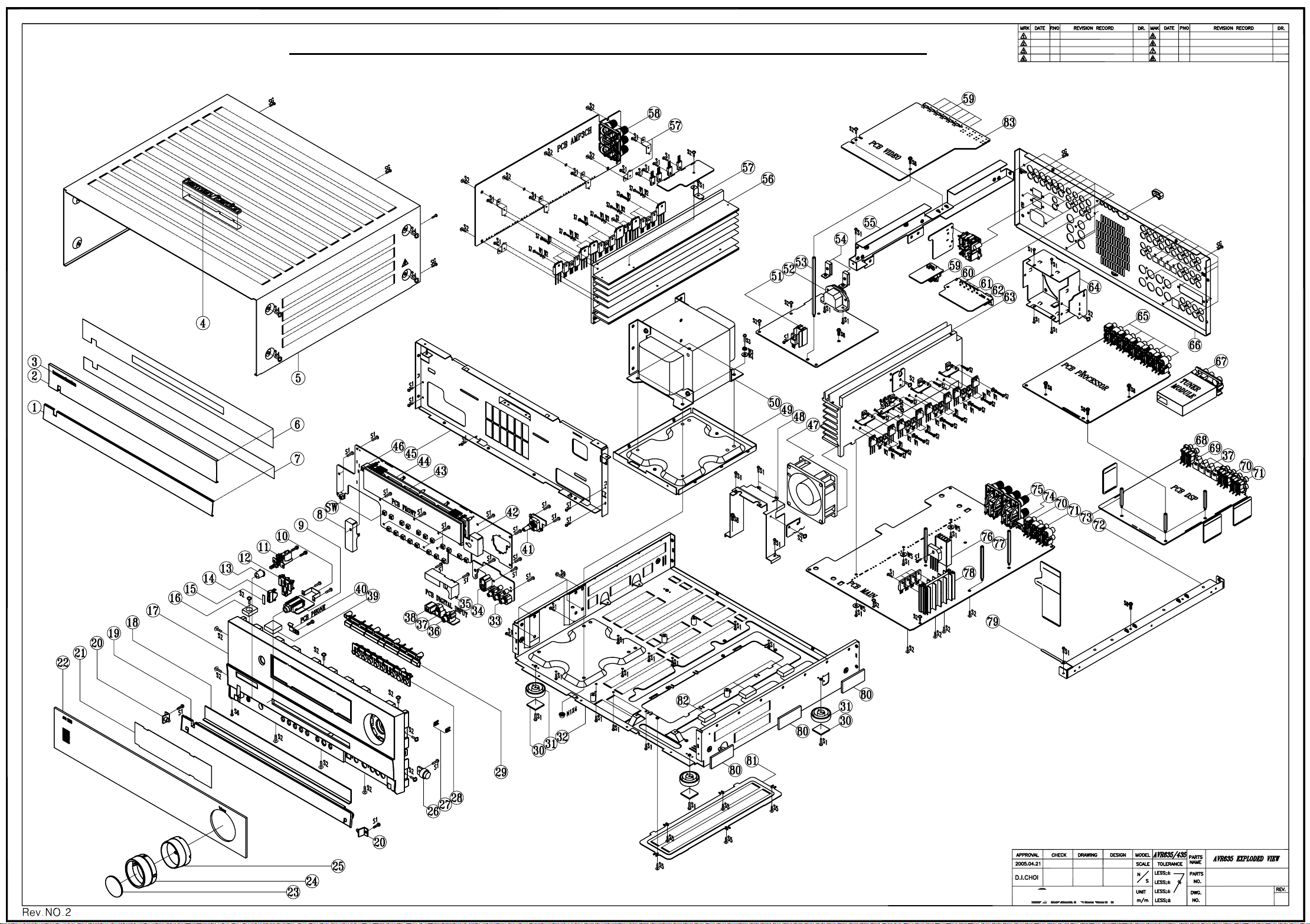
AVR435/635 harman/kardon
27
Page 28

Y
Y
AVR435/635 harman/kardon
28
AVR 435/635 EXPLODED VIEW PART LIST
NO
1 H03-ZMC11S00200-6 AL DOOR AVR 1
2 H03-ZMC11S00300-8 AL PANEL AVR 1
3 H03-ZMC12S20A00-8 BADGE AL HARMAN/KARDON SILVER 1
4 H03-ZMGEN00GAGY-6 AL LOGO BADGE TOP 1
5 H03-ZMC11S08A00-0 COVER TOP AVR 1
6 H03-ZVC11DWT200-0 TAPE PANEL 1
7 H03-ZVC11DWT100-9 TAPE DOOR 1
8 H03-ZMD12S01A00-9 SHIELD IR 1
9 H03-SOSS9CKX3NN-4 JACK PHONE 6.35 H70980110S 9P BK 1
10 H03-ZMB01S00100-0 BKT HEADPHONE JACK 1
11 H03-SWA2B21PDAA-2 SW PUSH POWER SDDLB15700 5A 250V 1
12 ZPC1006GAWH-0 BUTTON STANDBY 1
13 ZPC1003GAGY-5 BUTTON POWER 1
14 ZPC1007GAMW-9 INDICATOR STAND-BY 1
15 H03-ZMC11S12A00-3 CAP BUTTON STAND-BY 1
16 ZFD122062SB-5 RUBBER TOP 20X15X6.2t 1
17 ZPD1201GAGY-4 PANEL FRONT 1
18 H03-ZMC11S14A00-5 BKT DOOR 1
19 ZPC1002GAGY-9 DOOR AVR 1
20 H03-ZMD05S16A00-9 BKT HINGE 2
21 H03-ZPC1018GART-2 FILTER VFD 1
22 H03-ZPD1219GABT-A H03-ZPD1119GABT-1 WINDOW DISPLAY AVR435/635+BADGE NAME 1
23 H03-ZPD0317GACR-A CAP KNOB VOLUME 1
24 H03-ZPD0316GASG-5 COVER KNOB 1
25 H03-ZPD0315GAMW-9 VOLUME KNOB 1
26 H03-ZVC11GEAR01-5 DAMPER GEAR DP120 1
27 ZPC1102GAMW-1 INDICATOR VIDEO 4 2
28 ZPC1005GAGY-8 BUTTON 8 KEY 1
29 H03-ZPC1004GASG-6 BUTTON 7 KEY 1
30 ZFNR19720SB-5 RUBBER FOOT 19.7X19.7X2T BK 4
31 ZPC1103GAGY-A FOOT 50MM 15.8MM 4
32 H03-ZMC11S13A00-4 CHASSIS MAIN 1
33 H03-SORA3313PNN-9 JACK RCA 3P YWR 1
34 H03-SORA8OSC5N8-8 JACK S-VIDEO 1P C40160261N 1
35 H03-ZMC12S17A00-6 SHIELD DIGITAL 1
36 H03-SORA1JE01NN-6 JACK RCA 1P JE010003MN GND OR 1
37 H03-SOTOR179LBA-6 D-LEM TORX-179L 4
38 H03-SO3P5179NNN-A JACK PHONE 3.5PI PJ0435179N 1
39 ZFD122072SB-2 RUBBER TOP 20X20X7.2t 1
40 H03-ZMC11S06A00-9 SPRING STOPPER 1
41 H03-SWE3A0505S1-4 SW ROT EC16B24204 5V 500U0A 10T 3P 0 0 1
42 H03-ZMD12S01B00-0 SHIELD MICROPHONE 1
43 H03-VDHCA18LL03-2 FL HCA-18LL03 1
44 ZPC1017GABK-6 HOLDER VFD 1
45 H03-ZMC11S07A00-A CH FRONT 1
46 ZFNR1SENSOR-0 RUBBER SENSOR 1
47 H03-ZVC11FAN100-1 FAN JF0925S1L 1
48 H03-ZMC11S09A00-1 BKT FAN FRONT 1
49 H03-ZMC12S08B00-0 BKT TRANS BOTTOM 1
50 H03-TXPWMM635B0-9 H03-TXPWMM435B0-2 POWER TRANSFORMER 1
51 H03-ZMC12HS0100 HEATSINK 17*15*30 1
52 H03-SOPA21275BK-9 AC OUTLET 2P 110V FE 12.75MM 2 BK 0 0 A204D0043P 1
53 ZMC12S15AYE-6 STANDOFF HEX M4X0.7 6X111.2H 1
54 H03-ZMC12S19A00-8 BKT AC INLET 2
55 H03-ZMD12S04B00-3 BKT FRAME GUIDE 1
56 H03-ZMD12HS0100-5 HEATSINK H/SINK AMP 1
57 H03-ZMC12S09A00-A BKT HEATSINK 7
58 H03-SOPA8SH0612-5 JACK SPEAKER 6P SH0612707P 1
59 H03-SORA11Y00NN-0 JACK RCA+S VIDEO C5016031DN 7
60 H03-ZMC12S16A00-5 BKT GROUND 1
AVR435/635 AVR435 ONL
DESCRIPTION QT
Page 29

Y
Y
AVR435/635 harman/kardon
29
NO
61 H03-SOJW2350SNN-0 JACK PHONE 3.6 EP-1401A 1P BK 4
62 SOPA96063NN-0 JACK D-SUB 9P 87204-6063 W/DUST COVER BK 1
63 H03-ZMC11HS0200-2 H/SINK MAIN 1
64 H03-ZMC11S10A00-1 BKT FAN REAR 1
65 H03-SORA40GNDNN-2 JACK RCA 4P JB040131PN WWRR 5
66 H03-ZMD12S02A00-A H03-ZMD11S02A00-1 PANEL REAR 1
67 H03-ZVC11TUNE01-2 TUNER MODULE KST-MB011MW0-81 US 1
68 H03-SOJB04013HN-0 JACK RCA 4P OR ,OR, OR, OR JB040131HN 1
69 H03-SOTOT179LBA-2 D-LEM TOTX-179L 1
70 H03-SORA40RSANN-1 JACK RCA 4P JB040131ZN GN BN PP TA 2
71 H03-SORA40RSCNN-5 JACK RCA 4P JB040131QN WH BU RD GY 2
72 H03-ZMC11S04B00-9 BKT FRAME GUIDE 1
73 ZMC12S13AYE-1 STANDOFF HEX M4X0.7 6X31.9H 3
74 SO0A18P8CNN-7
75 H03-SOPA81900NN-3 TERMINAL SPKR 8P SH081136JP FE 19MM 8 -- 0 0 1
76 H03-ZMC11HS0400-6 HEATSINK DIODE 47X26X12 AVR630 -- ME 1
77 ZMC12S14AYE-9 STANDOFF HEX M4X0.7 6X61.9H 3
78 H03-ZMD11HS0400-2 HEATSINK REG. TR 68X20X50 1
79 ZMC1221AA00-9 CLAMP WIRE-FIX UL 55212250 1
80 ZFNR13830SB-6 RUBBER SIDE 50X22X3t 6
81 H03-ZMC12S07A00-8 COVER BOTTOM 1
82 ZUC1201AABK-7 SPONGE 30X30X10T BK 3
83 H03-SOR12BJ12NN-9 JACK RCA 12P BJ120154JN 1
SW H03-SWC2A112FS1-3 SWITACT TACT SKQNADD010 12V 50MA 20
AVR435/635 AVR435 ONL
JACK-TELE SNAP-IN GOLDEN TELECOM GDL1-8P8C 8T
BK 0 0
H03-ZMB01S02200-4 SPRING PLATE GND C5212 0.2T 8
DESCRIPTION QT
1
N1 ZNSSM4045HZ-4 NUT M4 HEXAGON CIRCULAR EXTERNAL 4
S1 ZSTBM3010BB-5 SCREW ST BH 3X10 64
S2 ZSTWM3008BY-8 SCREW ST WPH 3X8 49
S3 ZSMCM4010BB-5 SCREW BM 4X10 4
S4 ZSTWM4008BC-3 SCREW ST WPH 4X8 SILVER CHROM 12
S5 ZSTWM3006BB-3 SCREW ST WPH 3X6 7
S7 ZSTBM3012BY-A SCREW ST BH 3X12 PIVOT 36
S8 ZSMCM4008BY-1 SCREW BM 4X8 5
SG ZSTGM3010BB-3 SCREW ST BH 3X10 GROUND 50
W1 ZWM623108SZ-2 WASHER SPRING 3 39
W2 ZWM803305PZ-1 WASHER PLAIN 3 20
W3 ZWM763109SZ-2 WASHER SPRING 4 4
W4 ZWMC04810PZ-5 WASHER PLAIN 4 4
Page 30

AVR435/635 harman/kardon
30
harman/kardon TECH TIPS
Troubleshooting tips and solutions to common service problems
For models:
AVR7000/7200/7300/8000
AVR100/200/300/500
AVR110/210/310/510
AVR120/220/320/520
AVR125/225/325/525
AVR130/230/330/430/630
AVR135/235/335/435/635
AVR10
DPR1001
DPR1005
DPR2005
HK3370/3470/3375/3475
HK3250
Subject: Backup Memory on AVR/DPR/HK series receivers
In the event of the complaint: “the receiver is losing its memory (any programmed system set t in gs)
when the unit is turned off, or after the unit is unplugged (briefly*)”:
Check and replace:
Model Designator Location Description Part number
AVR10
AVR7000 C730 Front PCB 0.047 Farad 5.5v capacitor
AVR7200 C106 Front PCB 0.047 Farad 5.5v capacitor # 55134360
AVR7300 C657 DSP PCB 0.047 Farad 5.5v capacitor # H01-CEZXA0479MN-5
AVR8000 C726 Front PCB 0.047 Farad 5.5v capacitor
AVR100/200 C412 Front PCB 0.047 Farad 5.5v capacitor # CEGT-B473J-0J0
AVR300 C906 Front PCB 0.1Farad 5.5v capacitor
AVR500 C906 Front PCB 0.1Farad 5.5v capacitor
AVR110/210/310/510
AVR120/220/320/520
AVR125/225 C734,C885 Front PCB two 0.1F capacitors in parallel # BCESOHD104
AVR325/525 C106 Front PCB 0.047 Farad 5.5v capacitor # 55134360
AVR130/230/330 BAT1 Front PCB 3.6v Battery # HABGP40BVH3A3H
AVR135/235/335 BAT1 Front PCB 3.6v Battery # HGP15BNH3A3H
AVR430/630 C657 DSP PCB 0.047 Farad 5.5v capacitor # CEZXA0479MN-5
AVR435/635 C557 DSP PCB 0.047 Farad 5.5v capacitor # H03-CEZXA0479MN-0
DPR1001 BC601 Main PCB 0.1Farad 5.5v capacitor # CEGT-B104J-0J0
DPR1005/2005 C437
HK3370/3470 C301 Front PCB 0.1Farad 5.5v capacitor # CEGT-B104J-0J0
HK3375/3475 C301 Front PCB 0.1Farad 5.5v capacitor # CEGT-B104J-0J0
HK3250
* After approximatel y two weeks of being disconnected from AC supply, even a normally functioning receiv er may
lose any program med setti ngs and switch t o default settings. (Four weeks for the DPR1005 & 2005)
C712
D709
C216 Front PCB 0.047 Farad 5.5v capacitor # 55134360
C712
D709
Front PCB
Processor
PCB
Front PCB
0.047 Farad 5.5v capacitor
and 1N4148 diode
0.047 Farad 5.5v capacitor # CEZXA0479MN-5
0.047 Farad 5.5v capacitor
and 1N4148 diode
TIP# HKTT2003-01 Rev4
#3439247315
#2058322101
# 55134360 or
# J3432147324X
# 55230310NR or
# 55134360
# J4433210421X
or # P10791-ND
# J4433210421X
or # P10791-ND
#3439247315
#2058322101
Page 31

AVR435/635 harman/kardon
31
AVR435/635 IDLE ADJUSTMENT PROCEDURES
NO Signal/No Load
AC Line Voltage:120V/60Hz.230V/50Hz
1. MAIN AMP idle Adjustment
MAIN:VR71.VR72
SURROUND:VR73.VR74
1) After turning the unit ON wait at least 25 minutes before adjustment (to achieve normal power/Driver TR temperature)
2) Adjust the voltage value of primary&secondary of wafer to be 23mV by rotating the Potentiometer of each channel
CHANNEL ADJUSTMENT MEASUREMENT VOLTAGE
FRONT-L CH VR71 P801 23+/-2mV
FRONT-R CH VR72 P802 23+/-2mV
SURROUND-L CH VR73 P803 23+/-2mV
SURROUND-R CH VR74 P804 23+/-2mV
The corresponding channels should be adjusted again following the above procedure, when these Transistors are replaced:
FRONT AMP: Q433.Q434.Q435.Q436.Q337.Q338.Q339.Q340
SURROUND AMP: Q329.Q330.Q331.Q332.Q333.Q334.Q335.Q336
2. CENTER/SURROUND BACK AMP idle Adjustment
CENTER:VR501
SURROUND BACK:VR201.VR301
1) After turning the unit ON wait at least 25 minutes before adjustment (to achieve normal power/Driver TR temperature)
2) Adjust the voltage value of primary&secondary of wafer to be 23mV by rotating the Potentiometer of each channel
CHANNEL ADJUSTMENT MEASUREMENT VOLTAGE
CENTER VR501 P501 23+/-2mV
SUR BACK-L CH VR201 P201 23+/-2mV
SUR BACK-R CH VR301 P301 23+/-2mV
The corresponding channels should be adjusted again following the above procedure, when these Transistors are replaced:
CENTER AMP: Q516.Q517.Q518.Q519
SUR BACK AMP: Q216.Q217.Q218.Q219.Q316.Q317.Q318.Q319
CAUTION
When POWER TR or DRIVER TR need replacement,
On the MAIN & SUPPLY BOARD, the following capacitors should be discharged for 30 seconds
with a 4.7 Ohm 10W resistor after turning unit OFF, to preventing possible damage from an electrical spark.
MAIN BOARD
SUPPLY BOARD
C504.C505 AVR435 12000/63V
C571.C572 AVR635 15000/63V
C201.C202 AVR435 8200/63V
C201.C202 AVR635 10000/63V
Page 32

AVR435/635 harman/kardon
32
Page 33

33
Page 34

34
Page 35

AVR435 Mechanical Parts List harman/kardon
35
REF NO. PART NO. DESCRIPTION REMARKS
3SA-4120US-BC00-1-7 MECH BOM AVR435US HARMAN KARDON
H03-SWA2B21PDA&-2 SW PUSH POWER SDDLB15700 5A 250V
H03-TXPWMM435B0-2 TRANS MN X'FORMER 120V AVR435US
H03-WF15S2605FU-6 WIRE FFC (CARD CABLE) DHCDF-15/260-P1.25-AT
H03-WF27S2705FU-5 WIRE FFC (CARD CABLE)DHCDF-27/270-P1.25-AT
H03-ZMB01S00100-0 BKT HEADPHONE JACK
H03-ZMB01S02200-4 SPRING PLATE GND C5212 0.2T
H03-ZMC11HS0200-2 H/SINK MAIN AVR630
H03-ZMC11S00200-6 AL DOOR AVR430/630
H03-ZMC11S00300-8 AL PANEL AVR430/630
H03-ZMD12S04B00-3 BKT FRAME GUIDE AVR635
H03-ZMC11S06A00-9 SPRING STOPPER AVR430/630
H03-ZMC11S07A00-A CHASSIS FRONT AVR430/630
H03-ZMC11S08A00-0 COVER TOP AVR430/630
H03-ZMC11S09A00-1 BKT FAN FRONT AVR430/630
H03-ZMC11S10A00-1 BKT FAN REAR AVR430/630
H03-ZMC11S12A00-3 CAP BUTTON STAND-BY AVR430/630
H03-ZMC11S13A00-4 CHASSIS MAIN AVR430/630
H03-ZMC11S14A00-5 BRACKET DOOR
H03-ZMC12S07A00-8 COVER BOTTOM
H03-ZMC12S08B00-0 BKT TRANS BOTTOM
H03-ZMC12S09A00-A BKT HEATSINK
H03-ZMC12S19A00-8 BKT AC INLET
H03-ZMC12S20A00-8 BADGE AL HARMAN/KARDON SILVER
H03-ZMD05S16A00-9 BKT HINGE AVR7300
H03-ZMC11S04B00-9 BKT FRAME GUIDE
H03-ZMD11HS0100-7 HEATSINK H/SINK AMP AVR435
H03-ZMD11S02A00-1 PANEL REAR AVR435US
H03-ZMGEN00GAGY-6 AL LOGO BADGE TOP
H03-ZPC1004GASG-6 BUTTON 7 KEY
H03-ZPC1018GART-2 FILTER VFD
H03-ZPD0315GAMW-9 VOLUMN KNOB
H03-ZPD0316GASG-5 COVER KNOB
H03-ZPD0317GACR-A CAP KNOB VOLUMN
H03-ZPD1119GABT-1 WINOW DISPLAY AVR435+BADGE NAME AVR435
H03-ZVC11DWT100-9 TAPE DOOR
H03-ZVC11DWT200-0 TAPE PANEL
H03-ZVC11FAN100-1 FAN JF0925S1L
H03-ZVC11GEAR01-5 DAMPER GEAR DP120
H03-ZVC11TUNE01-2 TUNER MODULE KST-MB011MW0-81 US
ZFD122062SB-5 RUBBER TOP AVR635
ZFD122072SB-2 RUBBER TOP AVR635
ZFNR13830SB-6 RUBBER SIDE
ZFNR19720SB-5 RUBBER FOOT 19.7X19.7X2T BK
ZTB017030AA-4 CABLE TIE 100MM NYLON 6
ZKC1095HA00-0 LABEL LICENSE AVR430
ZKC1222HA00-2 LABEL RISK
ZKC1229HA00-7 LABEL DATE
ZKGEN29HA00-8 LABEL DATE BLANK
ZKC1281HA00-9 LABEL QC CHECK
ZKD1130HA00-3 LABEL SERIAL AVR435US
ZKGEN30HA00-6 LABEL SERIAL BLANK
ZKD1173HA00-4 LABEL BARCODE AVR435US
ZKGEN73HA00-7 LABEL BARCODE BLANK
ZKGEN97HA00-3 LABEL MAIN POWER REMIND
ZMC12S13AYE-1 STANDOFF HEX M4X0.7 6X31.9H
ZMC12S14AYE-9 STANDOFF HEX M4X0.7 6X61.9H
ZMC12S15AYE-6 STANDOFF HEX M4X0.7 6X111.2H
ZNSSM4045HZ-4 NUT M4 HEXAGON CIRCULAR EXTERNAL
ZPC1002GAGY-9 DOOR AVR430/630
ZPC1003GAGY-5 BUTTON POWER
Page 36

AVR435 Mechanical/Packing Parts List harman/kardon
36
REF NO. PART NO. DESCRIPTION REMARKS
ZPC1005GAGY-8 BUTTON 8 KEY
ZPC1006GAWH-0 BUTTON STANDBY
ZPC1007GAMW-9 INDICATOR STAND-BY
ZPC1017GABK-6 HOLDER VFD AVR430/630
ZPC1103GAGY-A FOOT 50MM 15.8MM
ZPD1101GAGY-A PANEL FRONT AVR435
ZVC11FILM0A-A PROTECTION FILM
ZSMCM4008BY-1 SCREW BM 4X8
ZSMCM4010BB-5 SCREW BM 4X10
ZSTBM3008BY-1 SCREW ST BH 3X8
ZSTBM3010BB-5 SCREW ST BH 3X10
ZSTBM3012BY-A SCREW ST BH 3X12 PIVOT
ZSTGM3010BB-3 SCREW ST BH 3X10 GROUND
ZSTWM3006BB-3 SCREW ST WPH 3X6
ZSTWM3008BY-8 SCREW ST WPH 3X8
ZSTWM3A08BY-6 SCREW ST W7.5PH 3X8
ZSTWM4008BC-3 SCREW ST WPH 4X8 SILVER CHROM
ZUC1201AABK-7 SPONGE 30X30X10T BK
ZV4P00030TH-3 HEAT SHRINK TUBE L30MM*D4.0MM*T0.5MM
ZWF793008PO-5 WASHER FIBER 3 0.8T
ZWM623108SZ-2 WASHER SPRING 3
ZWM763109SZ-2 AC SPRING WASHER RT2250(PAV5005)
ZWM803305PZ-1 WASHER PLAIN 3
ZWMC04810PZ-5 WASHER PLAIN 4
H03-WF09SB81300-3 WIRE ASS'Y UL1007#26 STR 130MM 2.0MM 9P WHT
H03-WF4261805BN-7 WIRECONASY DL 2.0MM 4P 180MM UL 1007 RIBBON 26 1
H03-WG02SG8532A-4 WIRECONASY UNIQUE 2P 530MM UL1617 PVC DOUBLE INSULATED 20 1
H03-FBB0102AA00-2 FCORE FERRIT MAGNET SRH9. 9X20. 0X5. 3
H03-FBD0480BR00-8 FCORE CLAMP FILTER LF80BR W5 SRH 16X28X9
H03-ZUD0301AABK-5 SPONGE-UL 30X30X12T BK DPR2005
ZMC1221AA00-9 CLAMP WIRE-FIX UL 55212250
XY81204K4YW-5 GLUE, YELLOW, N.W=4.4KG #8120 @KG
XY1N218M3SW-4 GLUE FURROW W=12MML=18.3M SS WHITE @ROLL
XY501110CRD-2 GLUE, RED #AK-501 F/SCREW V=110CC @BOTTL
XY2N450M0DW-6 GLUE,TAPE,#9070,W=24MM,L=50,DOUBLE-SIDE,WHITE. @METER
XY1N055M0DW-7 GLUE TAPE , W=10MM L=55M DOUBLE-SIDE ,WHITE,#3M9495LE. @M
XYEM501K000-2 SPECIALTY LUBRICANTS GREASE,#EM-50L,W=1KG @G
H03-RYC1202HA00-0 REMOCON ZONE 2
H03-RYD1101HA00-0 REMOCON AVR435US
H03-WAUSA2103BK-7 POWER CORD WS-004C+002E SJT#14*2C L=2M
H03-ATALF039ABK-5 ANTENNA WIRE AM LOOP CT01-AM 0 0
H03-WAB01200203-4 FM ANTENNA WIRE 75 CT02-FM 0 0
ZKC1113HA00-9 CARD WARRANTY
ZKD1116HA00-0 QUICK SETUP GUIDE AVR435
ZKC1214HA00-A LABEL SAFETY LEAFLET
ZKC1263HA00-0 INSERT RS232 NOTE PAPER
ZKD1101HA00-3 OWNER'S MANUAL AVR435US
ZKD1104HA00-2 BOX CARTON AVR435US
ZQD1201HAWH-A CUSHION POLY EPS RIGHT AVR635
ZQD1202HAWH-6 CUSHION POLY EPS LEFT AVR435/635
H03-MCD12TWBKNN-8 AVR43 5/635 MICRO PHO NE ASSY
H03-ZPD1212INBK-5 MICROPHONE ASSY EXTENSION PIECE
ZKD1202HA00-4 CARTON BOX MIC
ZKD1263HA00-3 BROCHURE AVR US
Page 37

AVR435 Electrical Parts List harman/kardon
37
REF NO. PART NO. DESCRIPTION REMARKS
3SA-4120US-DGMI-1-6 IMA DSP BD AVR435US
C557 H03-CEZXA0479MN-0 CM 47MI0F +80%-20% 5.5V 70C SCDA5R5473V
IC851 H03-ICPC17T10B1-8 IC PHOTOCOUPLER PC-17T1 DIP4 KODENSHI
T701 H03-LF11030A2NA-A TFPULSE TRANSFORMER 110UH FP-110 FERRIT MAGNET
Y600 H03-OSCEM24M5RU-5 VCXO 24M576 HZ +50 PPM -50 PPM 0 OHM 3.3V
Y500 H03-OSCNI20MOCU-1 CSTLS20MOX51-B0
NJ705 H03-SOJB04013HN-0 JACK RCA 4P OR ,OR, OR, OR JB040131HN
NJ802 H03-SORA40RSANN-1 JACK RCA 4P JB040131ZN GN BN PP TA
NJ801 H03-SORA40RSCNN-5 JACK RCA 4P JB040131QN WH BU RD GY
NJ701 702 703 H03-SOTOR179LBA-6 D-LEM TORX-179L
NJ704 H03-SOTOT179LBA-2 D-LEM TOTX-179L
N803 H03-WG06SB82800-7 WIRE ASS'Y UL1007#26 STR 280MM 2.0MM 6P WHT
N501 H03-WG09SB81000-3 WIRECONASY DL 2.0MM 09P 100MM UL1007 RIBBON 26 1
N701 H03-WN05SB00000-6 CONN 2.0MM 5 MA ST NAT GT201-5P-TS
N504 H03-WN06AB00001-A CNT PLUG BD'BD SOCKET 2.0mm 35237-0610 6P
N506 H03-WN09SB00000-5 CONN 2.0MM 9 MA ST NAT GT201-9P-TS
N503 H03-WN11SB00000-3 CONN 2.0MM 11P MA ST NAT MOLEX 35336-1110 0 0
N802 H03-WN19AB00000-4 CONN 2.0MM 19 MA R NAT SOCKET MOLEX 35237-1910 0 0
N407 801 H03-WN19SB00000-1 CONN 2.0MM 19 MA ST NAT MOLEX 35336-1910 0 0
N502 H03-WN27AI00000-A CONNECT 1.25mm 27P GF120-27S-LS
IC507 H03-ICKA78R08I2-A IC-KIA78R08API TO-220IS-4PIN
L501 H03-LAINB047ACR-9 LF 4U7H +10% 1.7 OHM 190.0A
R521 RC3DI010AIN-1 RCF 1R0 OHM +5% 250MI0W
L702 703 704 705 H03-LAINB0470CR-8 LF 47U0H +10% 5.8 OHM 500MI0A
N805 H03-WG01S022018-5 WIRE ASS'Y UL1007#18 220MM 1P BLK TERMINAL
REWORK H03-WC1201005C1-4 WIRE ASS'Y UL1007 #20 TS 100MM 1P BLK
XY0P523K000-A WIRE,IRON,D=0.5MM,N.W=23KG @KG
XY0P801K000-A WIRE TIN D=0.8MM N.W=1.0KG @KG
XY1N209M0DW-4 GLUE TAPE W=12MM L=9.0M DS WHITE @ROLL
XY1N218M3SW-4 GLUE FURROW W=12MML=18.3M SS WHITE @ROLL
XY1P202K000-1 WIRE, TIN, D=1.2MM N.W=2.0KG @KG
XY30155G00-0 TCE,CLEANER,-301#,V=55GALL0N,TYPELESS @GALLON
XY4N836M5CL-9 GLUE TRANSPARENT W=48MM L=36.5M @ROLL
XY6R301K000-0 BAR,TIN,63/37,N.W=1.0KG @KG
XYALC01G000-2 ALCOHOL V=1.0GALLON @GALLON
XYGLU00K5RD-7 GLUE, RED, W=0.5KG TYPELESS FOR SMT @KG
XYJUI00K5GY-5 JUICE TIN N=0.5KG GREY @KG
XYRF801G000-7 FLUX #RF-800 V=1.0 GALLON @ GALLON
XYWAX10K000-6 ANTI-OXIDATION,WAX,W-1#,N.W=10KG,@KG
3SA-4120US-DGAR-1-6 IAR DSP BD RADIAL AVR435US
C411 431 432 433 CCKIC0471NC-9 CAP CERAMIC 470PF 50V K X7R TAP
C412 415 434 435 454 458 475
476 487 488 489 495
CCKIC0561NC-8 CAP CERAMIC 560PF 50V K X7R TAP
Page 38

AVR435 Electrical Parts List harman/kardon
38
REF NO. PART NO. DESCRIPTION REMARKS
C400 401 402 403 421 422 423
424 425 426 427 428 436 440
441 451 453 456 457 459 461
462 496 497 519 520 521 530
629 631 633 635 902
C514 CEHFC04762S-0 CE 47UF +20% 16V D5XL7 P2.5MM 2000hours 85C
C525 CEHIC01042S-5 CE 100NF +20% 50V SSE TYPE D4XL7 P2.5MM 85C
C416 417 418 419 429 430 438
439 450 460 470 471 481 482
483 484
C258 259 265 267 527 744 745 CEMFC01072E-8 CE 100UF 16V +/-20% 5X11 P2.5MM ELIET
C625 CEHIC01055E-6 CE 1UF +20% 50V D5XL11 P5MM 85C
C958 CEHIC04755E-6 CE 4U7F +20% 50.0V 85C P5MM
Q851 H03-TRKTA107MNA-2 TR-SLPSWA KRA107M P
Q511 H03-TRMPSA06NNA-A TR-SLPLF MPSA06 N 500MI0A TO-92
C823 824 825 CEHDC0108NN-3 CE 1MI0F +20% 6.3V 8X11.5 85C ELITE P5MM
C601 959 CEHEC0477MN-A CE 470U0F +20% 10.0V 6.3X11 85C ELITE P5MM
C264 508 515 623 821 822 904
912
CEHFC01062S-0 CE 10UF +20% 16V D4XL7 P2.5MM 2000hours 85C
CCKIC0272NC-4 CAPACITOR CERAMIC 2N7F 50V K X7R TAP
PBD11KDGB20-5 PCB DUALA VR435/635 DSP 209x170x1.6t FR-4 1OZ
CEHFC01072S-9 CE 100UF +20% 16V D6.3XL7 P2.5MM 2000hours 85C
3SA-4120US-DGSB-1-7 BOTTOM SMD DSP BD AVR435US
C501 502 504 505 506 801 802
803 804 805 806 807 808 809
810 811 812 813 814 815 816
C700 702 720 743 CZJII0220BE-5 CCCFMIC 22P0F +5% -5% 50.0V NP0 0603
C444 492 CZJII0470BE-4 CAP CHIP 47P0F +5% -5% 50.0V NPO 0603
C251 252 646 CZKII0102BC-7 CAP CHIP 1N0F +10% -10% 50.0V X7R 0603
C603 604 647 648 701 703 706
717
C257 263 292 503 507 513 516
517 518 522 528 614 615 622
624 628 630 632 634 705 708
710 714 721 817 818 903 910
913 922 925 926 927 930 945
947 961 980 981 982 984 985
986 988 989 990 991 929 946
960 987
C619 CZZII0104CF-8 CAP CHIP 100N0F +80% -20% 50.0V Y5V 0805
D503 504 505 507 851 H03-DS1S50094NB-5 D-SLP 1SS355 35.0V 225MI0A
L504 604 610 700 901 904 905 H03-FB2K52012NN-0 FBEAD SURFACE MT 2500OHM FCM2012H-252T02
L601 602 605 606 607 H03-FB3012012CN-8 FBEAD SURFACE MT FCM2012C-301T04 0805
L706 RS3BB0000NA-5 RES CHIP 0 OHM +5% 100MI0W 0805
E901 H03-FYACF333TNN-A FILTER ACF451832-333-T
IC502 H03-IC74HC4094D-1 IC CD74HC4094D(R-PDSO-G16) SOP16
IC608 H03-IC74LV1G125-9 IC SN74LVC1G125DVB SOT23
Q601 H03-TRDTC114YNI-0 TR-SSD DTC114YKA N 10K0 OHM 47K0 OHM
U906 908 909 910 RN3AY0220NA-4 RES NETWORK RCA 22OHM 1/16W 5% CN34JT220
JUM1 2 R601 RS3AD0000NA-0 RES CHIP 0 OHM +0% 62MI5W 0603
R708 RS3AD0100NA-7 RES CHIP 10R0 OHM +5% 62MI5W 0603
R531 607 608 646 711 715 C709
711 722
R528 529 530 532 803 804 807
808 811 815 816
CZJII0101BE-2 CAP CHIP 100P0F +5% -5% 50.0V NP0 0603
CZKII0103BC-5 CAP CHIP 10N0F +10% -10% 50.0V X7R 0603
CZZFI0104BF-8 CAP CHIP 100N0F +80% -20% 16.0V Y5V 0603
RS3AD0101NA-5 RES CHIP 100R0 OHM +5% 62MI5W 0603
RS3AD0102NA-3 RES CHIP 1K0 OHM +5% 62MI5W 0603
R257 258 523 534 535 561 923 RS3AD0103NA-1 RES CHIP 10K0 OHM +5% 62MI5W 0603
R265 266 414 415 448 449 480
491 492 499 556 702 706 724
730
RS3AD0104NA-A RES CHIP 100K0 OHM +5% 62MI5W 0603
Page 39

AVR435 Electrical Parts List harman/kardon
39
REF NO. PART NO. DESCRIPTION REMARKS
R405 416 417 418 419 425 426
429 430 431 445 446 483 484
485 486 609 612
R132 251 252 253 256 RS3AD0151NA-1 RES CHIP 150R0 OHM +5% 62MI5W 0603
R913 914 RS3AD0182NA-1 RES CHIP,1.8K,1/16W,+-5%,0603.
R812 RS3AD0332NA-8 RES CHIP 3K3 OHM +5% 62MI5W 0603
R736 738 741 RS3AD0222NA-4 RES CHIP 2K2 OHM +5% 62MI5W 0603
R801 802 805 806 809 813 814 RS3AD0223NA-2 RES CHIP 22K0 OHM +5% 62MI5W 0603
R658 RS3AD027ANA-3 RES, CHIP, 2.7, 1/16W, +/-5%, 0603
R263 RS3AD0512NA-6 RES CHIP 5K1 OHM +5% 62MI5W 0603
R853 915 921 922 924 RS3AD0392NA-1 RES CHIP 3K9 OHM +5% 62MI5W 0603
R262 400 401 402 403 411 412
444 452 459 460 474 475 476
477 478 479
R852 RS3AD0471NA-5 RES CHIP 470R0 OHM +5% 62MI5W 0603
R518 851 RS3AD0472NA-3 RES CHIP 4K7 OHM +5% 1/16W 0603
R522 555 737 739 740 RS3AD0473NA-1 RES CHIP 47K0 OHM +5% 62MI5W 0603
R439 440 447 454 456 457 489
490 703 704 709 726 743
R406 427 428 432 433 434 435
438 443 450 453 458 481 482
487 488
R710 RS3AD0621NA-1 RES CHIP 620R0 OHM +5% 62MI5W 0603
R810 RS3AD0682NA-3 RES CHIP 6K8 OHM +5% 62MI5W 0603
R700 701 705 723 RS3AD0750NA-1 RES CHIP 75R0 OHM +5% 62MI5W 0603
RS3AD0122NA-8 RES CHIP 1K2 OHM +5% 62MI5W 0603
RS3AD0432NA-4 RES CHIP 4K3 OHM +5% 62MI5W 0603
RS3AD0561NA-4 RES CHIP 560R0 OHM +5% 62MI5W 0603
RS3AD0562NA-2 RES CHIP 5K6 OHM +5% 62MI5W 0603
3SA-4120US-DGST-1-2 TOP SMD DSP BD AVR435US
C253 254 255 256 510 542 543 CZJII0101BE-2 CAP CHIP 100P0F +5% -5% 50.0V NP0 0603
C621 CZJII0102CC-3 CAP CHIP 1nF 50V X7R J 0805
C443 491 541 544 CZJII0470BE-4 CAP CHIP 47P0F +5% -5% 50.0V NPO 0603
C645 CZKII0103BC-5 CAP CHIP 10N0F +10% -10% 50.0V X7R 0603
C602 CZKII0223CC-5 CAP CHIP 22NF 50V B K X7R 0805
C260 261 413 414 447 448 449
455 490 493 509 526 723 742
901 918 919 920 921 928 948
949 950 951 952 953 954 955
956 957 962 963 964 965 966
967 968 969 970 971 972 973
974 975 976 977 978 983 992
620
C627 CZZII0104CF-8 CAP CHIP 100N0F +80% -20% 50.0V Y5V 0805
D501 502 506 508 H03-DS1S50094NB-5 D-SLP 1SS355 35.0V 225MI0A
L903 H03-FB2K52012NN-0 FBEAD SURFACE MT 2500OHM FCM2012H-252T02
L508 H03-FB3012012CN-8 FBEAD SURFACE MT FCM2012C-301T04 0805
IC904 H03-ICM317TO252-1 IC 3-TERMINAL POS VOL REG NJM317DL1 TO-252
IC504 H03-IC74VC244G5-1 IC-LOGIC 74VHC244A INVERTER CMOS
IC902 H03-ICAT49BV162-8 IC FLASH MEMORY AT49BV162AT-70TI 48T
IC606 H03-ICCS42518E6-8 IC LOGIC CS42518CQ QFP64
IC501 H03-ICD703033E1-0 IC-MICOM FLASH NEC UPD70F3033BGF 0228KK001 JAPAN QFP100
IC903 H03-ICK4S1616M6-4 IC-SDRAM K4S161622H-TC60 OR TC80
IC251 252 401 402 404 406 H03-ICLM02068D2-5 IC-OPERAMP NJM2068M-TE1 DUAL SOP8
IC503 H03-ICM24C04WD2-7 IC-EEPROM M24C04WMN6T
IC704 705 H03-ICSN74HCU04-6 IC SN74HCU04D
IC505 506 607 H03-IC74LV1G125-9 IC SN74LVC1G125DVB SOT23
IC901 H03-ICTMS320DA6-0 IC FLOATING-POINT DSP TMS320D610A PQFP208
Q501 502 503 504 505 506 507
508 509 510 602
R717 817 818 819 820 821 822
823 824 901 546 C716
CZZFI0104BF-8 CAP CHIP 100N0F +80% -20% 16.0V Y5V 0603
H03-TRDTC114YNI-0 TR-SSD DTC114YKA N 10K0 OHM 47K0 OHM
RS3AD0000NA-0 RES CHIP 0 OHM +0% 62MI5W 0603
Page 40

AVR435 Electrical Parts List harman/kardon
40
REF NO. PART NO. DESCRIPTION REMARKS
R503 504 505 506 507 508 631
633 634
R267 268 630 632 645 981 982
983 984 985 986
R509 510 511 512 513 514 515
604 967 968 659
R254 255 259 260 501 502 519
520 533 551 552 559 969
R916 917 918 919 RS3AD0182NA-1 RES CHIP,1.8K,1/16W,+-5%,0603.
R261 264 RS3AD0203NA-8 RES CHIP 20K0 OHM +5% 62MI5W 0603
R544 629 524 525 RS3AD0221NA-6 RES CHIP 220R0 OHM +5% 62MI5W 0603
R553 554 725 RS3AD0222NA-4 RES CHIP 2K2 OHM +5% 62MI5W 0603
R920 RS3AD0392NA-1 RES CHIP 3K9 OHM +5% 62MI5W 0603
R541 542 543 RS3AD0471NA-5 RES CHIP 470R0 OHM +5% 62MI5W 0603
R516 517 557 RS3AD0472NA-3 RES CHIP 4K7 OHM +5% 1/16W 0603
R727 RS3AD0473NA-1 RES CHIP 47K0 OHM +5% 62MI5W 0603
U902 903 904 905 907 RN3AY0220NA-4 RES NETWORK RCA 22OHM 1/16W 5% CN34JT220
R657 RS3BB0200NA-8 RES,CHIP,20R 1/10W +/-5%,0805
R644 RS3BB0332NA-2 RES,CHIP, 3.3K OHM 1/10W +/-5%., 0805
D853 854 855 856 H03-DL30B2015AA-5 D-LEM 30B3-20-15 GaN SUPER BLUE WATER CLEAR 15
D831 H03-DL3BA05V0BA-8 D-LEM BLUE/AMBER 3PIE RD RND CL L-3VYMBC
RM71 H03-ICRPM6938NN-9 IC-REMOTE RPM6938-RSIP-A3 RECEIVER 38KHZ
VR100 H03-SWE3A0505S1-4 SWIROT EC16B24204 5V 500U0A 10T 3P 0 0
DP1 H03-VDHCA18LL03-2 FL HCA-18LL03
N201 H03-WG03AB80900-8 WIRECONASY DL 2.0MM 03P 90MM ANG-DOWN UL1007 RIBBON 26 1 B2011HR2
N203 H03-WG07SB82000-A WIRE ASS'Y UL1007#26STR 200mm 2.0mm 7P WHT
N202 H03-WG08SD84000-7 WIRE ASS'Y UL1007#24 STR 400mm 2.5mm 8P WHT
P604 H03-WN06SB01000-4 CNT PLUG BD'BD PLUG 2.0mm 35336-0610 6P
P234 H03-WN11AB00000-6 CONN 2.0MM 11 MA R NAT SOCKET MOLEX 35237-1110 0 0
P233 H03-WN11SB00000-3 CONN 2.0MM 11P MA ST NAT MOLEX 35336-1110 0 0
P201 H03-WN15AI00001-2 CONNECT GF120-15S-LS 1.25mm 15P
N602 H03-WN19AB00000-4 CONN 2.0MM 19 MA R NAT SOCKET MOLEX 35237-1910 0 0
P602 603 H03-WN19SB00000-1 CONN 2.0MM 19 MA ST NAT MOLEX 35336-1910 0 0
P211 H03-WN27AI00000-A CONNECT 1.25mm 27P GF120-27S-LS
N204 H03-WS4261005FN-3 WIRE ASS'Y UL2547/1007#26 100MM 4P 2.0MM WHT
N222 H03-WS7260805EN-6 WIRE ASS'Y UL1533/1007#26 80MM 2.0MM 7P WHT SHILED
S2 4 5 6 7 H03-ZMB01S02200-4 SPRING PLATE GND C5212 0.2T
SH11 H03-ZMD12S01A00-9 SHIELD IR
SH12 H03-ZMC12S16A00-5 BKT GROUND
RM72 H03-DPLP200LNNN-2 PIN PHOTODIODE LP-200L
C127 CEHFC01075E-1 CE 100UF +-20% 16.0V D5XL11 P5MM 85C
SH22 H03-ZMD12S01B00-0 SHIELD MICROPHONE
RS3AD0100NA-7 RES CHIP 10R0 OHM +5% 62MI5W 0603
RS3AD0101NA-5 RES CHIP 100R0 OHM +5% 62MI5W 0603
RS3AD0102NA-3 RES CHIP 1K0 OHM +5% 62MI5W 0603
RS3AD0103NA-1 RES CHIP 10K0 OHM +5% 62MI5W 0603
3SA-4120US-FCMI-1-0 IMA FRONT BD AVR435US
ZFNR1SENSOR-0 RUBBER SENSOR
XY0N211N5WH-4 CABLE TIE W=0.2MM L=11.5CM WHITE @ STRIP
XY0N618M3SW-A GLUE FURROW W=6MM L=18.3M SS WHITE @ROLL
XY0P523K000-A WIRE,IRON,D=0.5MM,N.W=23KG @KG
XY0P801K000-A WIRE TIN D=0.8MM N.W=1.0KG @KG
XY1N127N0WH-5 ADHESIVE WHITE D=1.1CM L=27CM @KG
XY1N209M0DW-4 GLUE TAPE W=12MM L=9.0M DS WHITE @ROLL
XY1N218M3CL-9 GLUE TRANSPARENT W=12MM L=18.3M @ROLL
XY1N218M3SW-4 GLUE FURROW W=12MML=18.3M SS WHITE @ROLL
XY1N250M0DW-4 GLUE,TAPE,#9070,W=12MM,L=50,DOUBLE-SIDE,WHITE. @METER
XY1P202K000-1 WIRE, TIN, D=1.2MM N.W=2.0KG @KG
XY30155G00-0 TCE,CLEANER,-301#,V=55GALL0N,TYPELESS @GALLON
XY4N836M5CL-9 GLUE TRANSPARENT W=48MM L=36.5M @ROLL
XY6R301K000-0 BAR,TIN,63/37,N.W=1.0KG @KG
XYALC01G000-2 ALCOHOL V=1.0GALLON @GALLON
XYGLU00K5RD-7 GLUE, RED, W=0.5KG TYPELESS FOR SMT @KG
XYRF801G000-7 FLUX #RF-800 V=1.0 GALLON @ GALLON
Page 41

AVR435 Electrical Parts List harman/kardon
41
REF NO. PART NO. DESCRIPTION REMARKS
XYWAX10K000-6 ANTI-OXIDATION,WAX,W-1#,N.W=10KG,@KG
3SA-4120US-FCAA-1-9 IAA FRONT BD AXIAL AVR435US
C128 CCZID0104NA-2 CC 100N0F +80% -20% 50.0V F
D101 301 H03-DG1N04148NB-A D-SLP 1N4148 100.0V 150E-3A
L121 H03-LAINB0470CR-8 LF 47U0H +10% 5.8 OHM 500MI0A
L120 H03-LAINB047ACR-9 LF 4U7H +10% 1.7 OHM 190.0A
PBD11KFCI20-6 PCB SINGLE AVR435/635 FRONT PCB 400x163x1.6t FR-1 1OZ
R105 122 123 501 502 RC3DI0101IN-0 RCF 100R0 OHM +5% 250MI0W
R104 RC3DI0102IN-9 RCF 1K0 OHM +5% 250MI0W
R111 112 113 RC3DI0103IN-7 RCF 10K0 OHM +5% 250MI0W
R831 RC3DI0151IN-7 RCF 150 OHM 5% 1/4W
R120 121 RC3DI0471IN-0 RCF 470R0 OHM +5% 250MI0W
R832 RC3DI0331IN-5 RCF 330R0 OHM +5% 250MI0W
R518 RC3DI0182IN-7 RCF 1K8 OHM 5% 1/4W
R851 852 RC3DI0561IN-A RCF 560R0 OHM +5% 250MI0W
3SA-4120US-FCAR-1-0 IAR FRONT BD RADIAL AVR435US
C517 CEHEC02275E-9 CE 220UF +20% 10.0V D6.3XL11 P5MM 85C
C101 718 H03-CEMGC0476AH-0 CAP ELEC 47uF 25v M 5x11 SHL P5MM
C125 126 H03-CFHKA0473NN-9 CAP POLYESTER METAL 47NF 100V 20% CPM
S201 202 203 204 205 206 207
208 209 210 211 212 213 214
215 216 217 218 219 220
Q821 H03-TRMPSA06NNA-A TR-SLPLF MPSA06 N 500MI0A TO-92
Q823 H03-TRMPSA56YNA-0 TR-SLPLF MPSA56 Y P -500MI0A -300V
C503 504 H03-CEMFC01062R-8 CAP ELEC 10UF 16V M 3.5X5 SRE P2.5MM
C501 502 708 H03-CEMGC04762R-6 CAP ELEC 47UF 25V M 6.3X5 SRE P2.5MM
C709 CZKII0104CC-2 CAP CHIP 100NF 50.0V X7R K 0805
C120 121 122 404 717 900 CZJII0101BE-2 CAP CHIP 100P0F +5% -5% 50.0V NP0 0603
Q701 702 H03-TRKTC3875ND-A TRANSISTOR NPN KTC3875S SOT23
C703 705 707 CZJII0122CC-8 CAP CHIP 1n2F 50V SL J X7R 0805
C701 704 706 CZDII0100CE-7 CAP CERAMIC/CHIP 10PF 50V CH D N 0805
D110 H03-DSUDZ05V1NB-A DIODE ZENER UDZ5.1B 5.1V 200MI0W
C300 301 CZJII0821CE-0 CAP CHIP 820pF 50V SL J NP0 0805
C505 506 CZKII0221BA-3 CAP CHIP 220PF 50V K SL 0603
C201 211 CZKII0223BC-6 CAP CHIP 22N0F +10% -10% 50.0V X7R 0603
C102 124 521 CZZFI0104BF-8 CAP CHIP 100N0F +80% -20% 16.0V Y5V 0603
D701 702 715 H03-DS1S50094NB-5 D-SLP 1SS355 35.0V 225MI0A
IC101 H03-IC74HC4094D-1 IC CD74HC4094D(R-PDSO-G16) SOP16
IC50 H03-ICLM02068D2-5 IC-OPERAMP NJM2068M-TE1 DUAL SOP8
Q824 831 832 833 H03-TRDTA114YNI-4 TR-SSD DTA114YKA P 10K0 OHM 47K0 OHM
Q820 822 H03-TRDTC114YNI-0 TR-SSD DTC114YKA N 10K0 OHM 47K0 OHM
Q703 704 705 H03-TRKTA1504ND-2 TRANSISTOR PNP KTA1504Y(S)SOT-23
C702 CZJII0101CE-1 CAP CERAMIC/CHIP 100PF 50V CH J NPO 0805
R746 RS3AD0101NA-5 RES CHIP 100R0 OHM +5% 62MI5W 0603
R101 102 103 201 211 503 515
824
R505 822 RS3AD0103NA-1 RES CHIP 10K0 OHM +5% 62MI5W 0603
R516 RS3AD0104NA-A RES CHIP 100K0 OHM +5% 62MI5W 0603
R202 212 RS3AD0122NA-8 RES CHIP 1K2 OHM +5% 62MI5W 0603
R203 213 RS3AD0152NA-A RES CHIP 1K5 OHM +5% 62MI5W 0603
R209 219 RS3AD0183NA-A RES CHIP 18K0 OHM +5% 62MI5W 0603
R823 RS3AD0221NA-6 RES CHIP 220R0 OHM +5% 62MI5W 0603
R204 214 510 519 RS3AD0222NA-4 RES CHIP 2K2 OHM +5% 62MI5W 0603
R205 215 RS3AD0272NA-0 RES CHIP 2K7 OHM +5% 62MI5W 0603
R206 216 506 RS3AD0332NA-8 RES CHIP 3K3 OHM +5% 62MI5W 0603
R509 RS3AD0472NA-3 RES CHIP 4K7 OHM +5% 1/16W 0603
R520 RS3AD0473NA-1 RES CHIP 47K0 OHM +5% 62MI5W 0603
R207 217 RS3AD0562NA-2 RES CHIP 5K6 OHM +5% 62MI5W 0603
R821 RS3AD0563NA-0 RES CHIP, 56K 1/16W +/-5%, 0603.
R301 302 RS3AD0683NA-1 RES CHIP 68K0 OHM +5% 62MI5W 0603
H03-SWC2A112FS1-3 SWITACT VERTICAL SKQNADD010 12V 50MA
3SA-4120US-FCST-1-7 SMD FRONT BD AVR435US
RS3AD0102NA-3 RES CHIP 1K0 OHM +5% 62MI5W 0603
Page 42

AVR435 Electrical Parts List harman/kardon
42
REF NO. PART NO. DESCRIPTION REMARKS
R208 218 RS3AD0822NA-2 RES CHIP 8K2 OHM +5% 62MI5W 0603
R508 RS3AD0911NA-3 RES CHIP 910 OHM +5% 62MI5W 0603
R702 704 709 710 RS3BB0103NA-6 RES,CHIP,10K 1/10W +/-5%,0805
R706 707 RS3BB0105NA-2 RES,CHIP,1M 1/10W +/-5%,0805
R703 RS3BB0272NA-5 RES,CHIP,2.7K 1/10W +/-5%,0805
R708 RS3BB0511NA-2 RES,CHIP,510 1/10W +/-5%,0805
R701 RS3BB0683NA-6 RES,CHIP,68K 1/10W +/-5%,0805
R711 715 RS3CB0102NN-8 RES,CHIP,1K,1/8W,+/-5%,0805
R714 RS3BB0471NA-A RES, CHIP 470 OHM 1/10W +/-5%, 0805
R705 RS3BB0564NA-3 RES,CHIP,560K OHM,1/10W +/-5%,0805
R712 713 RS3BB0221NA-0 RES,CHIP,220R 1/10W +/-5%,0805
3SA-4120US-FCMI-1-0 V4-DIG BD AVR435US
C400 401 403 CZJII0101BE-2 CAP CHIP 100P0F +5% -5% 50.0V NP0 0603
C411 CZZII0104CF-8 CAP CHIP 100N0F +80% -20% 50.0V Y5V 0805
D401 411 412 H03-DS1S50094NB-5 D-SLP 1SS355 35.0V 225MI0A
N220 H03-WS4264822EN-A WIRECONASY DL 2.0MM 04P 480MM UL1533 SHIELD 26 1 2/2
N221 H03-WS6265105EN-8 WIRECONASY DL 2.0MM 6P 510MM UL1533 SHIELD 26 1
NJ20 H03-SORA3313PNN-9 CON PHONO SCKT RCA-313P 3 PINS
NJ21 H03-SORA8OSC5N8-8 JACK S-VIDEO 1P C40160261N
P222 H03-WN07AB00000-3 CONNECT 2.0MM 7P GIL-S-07P-S2L2-EF
Q401 800 801 802 803 H03-TRDTC114YNI-0 TR-SSD DTC114YKA N 10K0 OHM 47K0 OHM
R841 842 843 844 RS3AD0000NA-0 RES CHIP 0 OHM +0% 62MI5W 0603
SK40 H03-RLV23079A10-6 RELAY V23079-A1001
SK40 H03-RLTX25VNAIS-2 RELAY TX2-5V STANDARD PC BOARD TERMINAL
3SA-4120US-FCMI-1-0 HP BD AVR435US
C1 4 CZZFI0104BF-8 CAP CHIP 100N0F +80% -20% 16.0V Y5V 0603
D1 2 H03-DS1S50094NB-5 D-SLP 1SS355 35.0V 225MI0A
L1 H03-LAINB0470CR-8 LF 47U0H +10% 5.8 OHM 500MI0A
N240 H03-WS4265913FN-0 CNT ASSY 2.0MM 4P 590MM SHIELD 26AWG UL2547 1/3
NJ88 H03-SOSS9CKX3NN-4 JACK PHONE 6.35 H70980110S 9P BK
R1 2 RC3DI022AIN-2 RCF 2R2 OHM +5% 250MI0W
S1 H03-ZMB01S02200-4 SPRING PLATE GND C5212 0.2T
3SA-4120US-FCMI-1-0 RMT/RS232 BD AVR435US
BD11 H03-FB3012012CN-8 FBEAD SURFACE MT FCM2012C-301T04 0805
C601 CPIKC0473NN-0 CPF 47N0F +10% 100.0V
C602 603 604 H03-CEMIC0334AH-A CAP ELEC 0.33UF M 5X11 SHL 50V SAMYOUNG P5MM
C605 RS3AD0000NA-0 RES CHIP 0 OHM +0% 62MI5W 0603
C606 611 622 CZZFI0104BF-8 CAP CHIP 100N0F +80% -20% 16.0V Y5V 0603
C610 CEHFC01075E-1 CE 100UF +-20% 16.0V D5XL11 P5MM 85C
C612 RS3AD0000NA-0 RES CHIP 0 OHM +0% 62MI5W 0603
C9 CEMIC01045E-1 CAP ELEC 0.1uF 50v M 5x11 SHL P5MM
D602 603 604 605 RS3AD0000NA-0 RES CHIP 0 OHM +0% 62MI5W 0603
D606 607 651 652 653 H03-DS1S50094NB-5 D-SLP 1SS355 35.0V 225MI0A
IC61 H03-ICMAX322316-7 IC RS-232 LINE DIRVER MAX3223CDWR SOIC16P
IC651 652 H03-ICPC17T10B1-8 IC PHOTOCOUPLER PC-17T1 DIP4 KODENSHI
L600 601 602 603 H03-FB2K52012NN-0 FBEAD SURFACE MT 2500OHM FCM2012H-252T02
NJ60 SOPA96063NN-0 JACK D-SUB 9P 87204-6063 W/DUST COVER BK
NJ611 612 613 614 H03-SOJW2350SNN-5 JACK PHONE 3.6 EP-1401A 1P BK
P260 H03-WN09AB00000-8 CONNECT 2.0MM 9P GIL-S-09P-S2L2-EF
Q651 652 H03-TRKTA107MNA-2 TR-SLPSWA KRA107M P
R600 601 602 RS3AD0472NA-3 RES CHIP 4K7 OHM +5% 1/16W 0603
R651 RS3AD0471NA-5 RES CHIP 470R0 OHM +5% 62MI5W 0603
R652 RS3AD0271NA-2 RES CHIP 270R0 OHM +5% 62MI5W 0603
R653 654 RS3AD0473NA-1 RES CHIP 47K0 OHM +5% 62MI5W 0603
R655 656 RS3AD0470NA-7 RES CHIP 47R0 OHM +5% 62MI5W 0603
R657 RS3AD0392NA-1 RES CHIP 3K9 OHM +5% 62MI5W 0603
Page 43

AVR435 Electrical Parts List harman/kardon
43
REF NO. PART NO. DESCRIPTION REMARKS
R658 RC3DI0104IN-5 RCF 100K0 OHM +5% 250MI0W
R659 RC3DI0471IN-0 RCF 470R0 OHM +5% 250MI0W
3SA-4120US-MAMI-1-3 IMA MAIN BD AVR435US
C509 510 CEHHC0228MN-A CE 2MI2F +20% 35.0V 85C ELITE
C517 CEHIA0228MN-4 CE 2MI2F +20% 50.0V 85C ELITE
C504 505 H03-CEMJA0129KB-8 CAP ELEC 12000uF 63V M 35x45 LSW123M1JQ45M
D501 H03-DRBU10040BA-1 D-BRDLC BRIDGE BU10-04
HS11 H03-ZMC11HS0400-6 AC HEATSINK DIODE 47X26X12 AVR630 -- ME
HS12 H03-ZMD11HS0400-2 HEATSINK REG. TR 68X20X50
P806 H03-WN07SB00001-4 CONN 2.0MM 7P GIL-S-7P-S2T2-EF
D502 505 H03-DRW204F00BA-5 DIODE BRIDGE W2-04F FRONTIER
IC59 H03-ICKIA7812I2-8 IC-REGPOSFXD KIA7812API NORMAL
IC54 H03-ICKIA7824I2-2 IC-REGPOSFXD KIA7824API TO-220IS NORMAL
IC51 H03-ICLM07815BD-6 IC-REGPOSFXD KIA7815API NORMAL
IC52 H03-ICLM07915BD-4 IC-REGNEGFXD KIA7915API NORMAL TO-220AB
L301 302 401 402 H03-LCNNNA050NA-7 LFA 1MM 10MM 5 LEFT 0.0MM NONE
R378 379 471 472 H03-RI3IC022BEN-3 RW 220MI0 OHM +5% 5.0W 100PPM/'C -100PPM/'C
R392 393 475 476 RM3FC0100BN-7 RMOF 10R0 OHM +5% 1.0W
R505 H03-RM3GC0100CN-2 RESISTOR METAL OXIDE 10R0 OHM +5% 2.0W
R514 H03-RM3GC022ACN-3 RESISTOR METAL OXIDE 2R2 OHM +5% 2.0W
R504 507 510 H03-RM3GC033ACN-2 RESISTOR METAL OXIDE 3R3 OHM +5% 2.0W
NJ12 H03-SORA40RSANN-1 JACK RCA 4P JB040131ZN GN BN PP TA
NJ11 H03-SORA40RSCNN-5 JACK RCA 4P JB040131QN WH BU RD GY
NJ14 H03-SOPA81900NN-3 CONN-SPE TERMINAL SPKR 8P SH081136JP FE 19MM 8 -- 0 0
Q335 336 439 440 H03-TR2SB1647B0-6 TRANSISTOR PNP 2SB1647 MT-100
Q333 334 437 438 H03-TR2SD2560B0-2 TRANSISTOR NPN 2SD2560 MT-100
Q319 320 421 422 H03-TRKTA1360BE-5 TRANSISTOR PNP KTA1360 TO-126
Q321 322 423 424 H03-TRKTC3423BE-A TRANSISTOR NPN KTC3423 TO-126
ZSMBM3014BZ-5 SCREW M.S M3X14 ZN PLATED
P801 802 803 804 809 H03-WN02SD00000-2 CONN 2.5MM 2 MA ST NAT 5267-02A 0 0
ZNSSM3023HZ-8 NUT M3 ZN PLATED
P807 H03-WN03SE00000-9 CON 3.96MM PITCH MOLEX 35313-0310
P808 H03-WN05SD100WH-6 CONN WAFER 2.5MM 5P 5267-05A WHT
P811 H03-WN19SB00000-1 CONN 2.0MM 19 MA ST NAT MOLEX 35336-1910 0 0
NJ13 SO0A18P8CNN-7 JACK-TELE SNAP-IN GOLDEN TELECOM GDL1-8P8C 8T BK 0 0
IC22 H03-ICLM02068D2-5 IC-OPERAMP NJM2068M-TE1 DUAL SOP8
N801 802 803 804 H03-WG02SB808AA-4 WIRECONASY UNIQUE 2P 80MM UL1007 PVC DISCRETE 26 BOTH
N805 H03-WS8262505EN-6 WIRE ASS'Y UL1533#26 250MM 2.0MM 8P WHT SHIELD
N806 H03-WSE263905EN-0 WIRECONASY DL 2.0MM 15P 390MM UL1533 SHIELD 26 1
N807 H03-WG03SB821AA-0 WIRECONASY DL 2.0MM 3P 210MM UL1007 RIBBON 26 12 BOTH
N808 H03-WG05SB84000-7 WIRE ASS'Y UL1007#26STR 400MM 2.0MM 5P WHT
N809 H03-WG03SB82200-4 WIRE ASS'Y UL1007#26STR 220mm 2.0mm 3P WHT
W311 H03-WG116S500BK-0 WIRE ASS'Y UL1007#16 500MM 1P BLK TERMINAL
W401-2 H03-WC1180905H1-0 WIRE ASS'Y WCL 1P 90MM UL1015#18(TD) BLK HOOK-UP 090-05-05
ZWM803305PZ-1 WASHER PLAIN 3
W301 H03-WC1180175H1-1 WIRE ASS'Y 1P 175MM UL1015#18(TD) BLK
R494 REWORK RC3DI0822IN-8 RCF 8K2 OHM +5% 250MI0W
XY0N211N5WH-4 CABLE TIE W=0.2MM L=11.5CM WHITE @ STRIP
XY0P523K000-A WIRE,IRON,D=0.5MM,N.W=23KG @KG
XY0P801K000-A WIRE TIN D=0.8MM N.W=1.0KG @KG
XY1N127N0WH-5 ADHESIVE WHITE D=1.1CM L=27CM @KG
XY1N218M3SW-4 GLUE FURROW W=12MML=18.3M SS WHITE @ROLL
XY1P202K000-1 WIRE, TIN, D=1.2MM N.W=2.0KG @KG
XY2N418M3SW-6 GLUE FURROW W=24MML=18.3M SS WHITE @ROLL
XY57501K0YW-0 GLUE, YELLOW, N.W=1.0KG #575 @KG
XY6R301K000-0 BAR,TIN,63/37,N.W=1.0KG @KG
XY74601K0WH-9 OINTMENT HTC #SDL-746 NW=1.0KG WHITE @KG
XYALC01G000-2 ALCOHOL V=1.0GALLON @GALLON
Page 44

AVR435 Electrical Parts List harman/kardon
44
REF NO. PART NO. DESCRIPTION REMARKS
XYRF801G000-7 FLUX #RF-800 V=1.0 GALLON @ GALLON
XYWAX10K000-6 ANTI-OXIDATION,WAX,W-1#,N.W=10KG,@KG
3SA-4120US-MAAA-1-1 IAA MAIN BD AXIAL AVR435US
C101 102 107 108 111 112 114
115 116 209
C313 314 569 570 CCKID0271NN-0 CC 270P0F +10% -10% 50.0V 2B4
C433 601 602 CCMFD0103NN-4 CC 10N0F +20% -20% 16.0V Y5S
C333 434 CCMFD0472NN-6 CC 4N7F +20% -20% 16.0V Y5R
C119 120 212 214 527 CCZID0104NA-2 CC 100N0F +80% -20% 50.0V F
D205 206 301 302 303 304 305
306 307 308 401 402 403 404
405 406 407 408 409 410 411
412
D101 507 508 509 H03-DR1N04004NA-7 D-SR 1N4004 400.0V 1.0A
D207 H03-DZMTZ05V1NB-3 DIODE ZENER MTZ J 5.1B 5.1V 500MW DO-34
D204 H03-DZMTZ12V0NB-6 D-ZENER MTZJ 12.0V 500MI0W
R351 352 367 368 445 446 447
448
R303 304 388 389 473 474 477
478
R213 215 221 609 614 RC3DI0101IN-0 RCF 100R0 OHM +5% 250MI0W
R211 601 RC3DI0102IN-9 RCF 1K0 OHM +5% 250MI0W
R485 516 605 606 608 610 611
613
R207 214 216 217 218 219 220
309 310 479 480 602
R311 312 313 314 380 381 386
387 405 406 407 408 481 483
488 490
R384 385 482 489 503 RC3DI0153IN-3 RCF 15K0 OHM +5% 250MI0W
R331 332 419 420 RM1DI1651IN-7 RMF 1K65 OHM +-1% 250MI0W
R317 318 319 320 409 410 411
412
R341 342 343 344 390 391 437
438 439 440 486 492
R616 RC3DI022AIN-2 RCF 2R2 OHM +5% 250MI0W
R321 322 413 414 497 RC3DI0271IN-8 RCF 270R0 OHM +5% 250MI0W
R209 498 RC3DI0273IN-4 RCF 27K0 OHM +5% 250MI0W
R224 RC3DI0274IN-2 RCF 270K0 OHM +5% 250MI0W
CCKID0101NA-7 CC 100P0F +10% -10% 50.0V Y5P
H03-DG1N04148NB-A D-SLP 1N4148 100.0V 150E-3A
H03-RM3EG0180LN-2 RMOF 18R0 OHM +5% 500MI0W
PBD11KMAI21-4 PCB SINGLE AVR435/635 MAIN 330x247x1.6t FR-1 1OZ
RC3DI0100IN-2 RCF 10R0 OHM +5% 250MI0W
RC3DI0103IN-7 RCF 10K0 OHM +5% 250MI0W
RC3DI0104IN-5 RCF 100K0 OHM +5% 250MI0W
RC3DI0152IN-5 RCF 1K5 OHM +5% 250MI0W
RC3DI0221IN-1 RCF 220R0 OHM +5% 250MI0W
RC3DI0223IN-8 RCF 22K0 OHM +5% 250MI0W
R301 302 401 402 RC3DI0331IN-5 RCF 330R0 OHM +5% 250MI0W
R363 364 365 366 461 462 463
464
R382 383 484 487 491 493 501
502
R307 308 415 416 RC3DI0433IN-8 RCF 43K0 OHM +5% 250MI0W
R223 RC3DI0513IN-A RCF 51K0 OHM +5% 250MI0W
R323 324 325 326 329 330 333
334 335 336 337 338 421 422
423 424 425 426 427 428 429
430 431 432
R347 348 349 350 441 442 443
444
C103 104 109 110 113 117 118 CCKID0470NA-9 CC 47PF +10% -10% 50.0V Y5P
R327 328 417 418 RM1DI0333IN-4 RMF 33K0 OHM +1% 250MI0W
R101 102 105 106 109 110 113
114 315 316 593 594
R607 612 RC3DI0123IN-1 RCF 12K0 OHM +5% 250MI0W
RC3DI033AIN-6 RCF 3R3 OHM +5% 250MI0W
RC3DI0393IN-5 RCF 39K0 OHM +5% 250MI0W
RC3DI0561IN-A RCF 560R0 OHM +5% 250MI0W
RC3DI0750IN-7 RES FILM 75 OHM 1/4W 5%
RC3DI0471IN-0 RCF 470R0 OHM +5% 250MI0W
Page 45

AVR435 Electrical Parts List harman/kardon
45
REF NO. PART NO. DESCRIPTION REMARKS
R225 305 306 403 404 RC3DI0333IN-1 RCF 33K0 OHM +5% 250MI0W
C307 308 403 404 CCKID0680NN-5 CC 68PF +10% -10% 50.0V 2B4
3SA-4120US-MAAR-1-3 IAR MAIN BD RADIAL AVR435US
C315 316 409 410 CCJIC0120NN-2 CAP CERAMIC 12PF 50V J CH TAP
C317 318 411 412 CCJIC0330NE-9 CAP CERAMIC 33PF 50V +-5% NPO
C329 330 425 426 CCKIC0222NA-1 CC 2N2F +10% -10% 50.0V Y5P
C331 332 407 408 CEHEC02275E-9 CE 220UF +20% 10.0V D6.3XL11 P5MM 85C
C432 CEMGC04775E-9 CE 470U0F +/-20% 25.0V 10X13 85C
C206 208 213 309 310 405 406
526
C210 CEHIC01055E-6 CE 1UF +20% 50V D5XL11 P5MM 85C
C301 302 401 402 429 518 519
521
C501 502 503 CFIOC0104NN-5 CPM 100N0F +10% 250.0V
C323 324 430 431 CFLJC0683NN-7 CPM 68N0F +5% 63.0V
C506 507 508 516 528 529 CPIKC0473NN-0 CPF 47N0F +10% 100.0V
Q443 H03-TRKRC107MNA-4 TR-SLPSWA KRC107M N
C207 H03-CEMIC0475AH-3 CE 4.7UF 50V M 5X11 SHL SAMYOUNG P5MM
C303 304 305 306 421 422 423
424
C211 319 320 413 414 H03-CEMKC0106AH-9 CAP ELEC 10UF 100V M 6.3X11 SHL
C325 326 327 328 417 418 419
420
F501 502 505 506 H03-FURN2200663-8 FUSE 663 SERIES 0663 002. 250V 2.0A TIMELUG
G101 102 H03-ZNMSA4004SN-A TERMLUG GND
Q442 H03-TRKTA1024NA-2 TR-SLPLF KTA1024 Y P 50MI0A -150V
Q605 607 H03-TRKTA1266NA-6 TR-SLPLF KTA1266 Y P 150MI0A
Q311 312 410 413 414 H03-TRKTA1268NA-A TR-SHPLF KTA1268BL P 100MI0A 120V
Q307 308 407 408 426 441 606
608
Q301 302 303 304 305 306 313
314 337 338 401 402 403 404
405 406 409 415 416 425
Q601 H03-TRKTD1302NA-6 TR-SLPLF KTD1302 B N 300MI0A 20V
Q309 310 411 412 H03-TR2SA1145NA-8 TR-SLPLF 2SA1145Y TO-92MOD P -50MI0A -150V
CEHGC01075E-5 CE 100U0F +20% 25.0V 6.3X11 85C P5MM
CEHIC01065E-4 CE 10U0F +20% 50.0V 85C P5MM 5X11
CEMJC02275E-0 CAP ELEC 220UF 63V M 10X16 85C 120HZ ELITE P5MM
H03-CPKJC0104NN-2 CAP POLY NON METAL 0.1UF 63V K TAP PCMT365 75104
H03-TRKTC3198NA-9 TR-SLPLF KTC3198BL N 150MI0A
H03-TRKTC3200NA-4 TR-SHPLF KTC3200BL N 100MI0A 120V
3SA-4120US-MAMI-1-3 FRONT L - BIAS BD AVR435US
R705 RC3DI0821IN-A RCF 820R0 OHM +5% 250MI0W
R707 RC3DI0282IN-3 RCF 2K8 OHM +5% 250MI0W
VR71 RT6BA0201NB-A PR 200R0 OHM +30% 100MI0W
Q701 H03-TRKTC3114NE-9 TRANSISTOR NPN KTC3114 TO-126
3SA-4120US-MAMI-1-3 FRONT R - BIAS BD AVR435US
R710 RC3DI0282IN-3 RCF 2K8 OHM +5% 250MI0W
R708 RC3DI0821IN-A RCF 820R0 OHM +5% 250MI0W
VR74 RT6BA0201NB-A PR 200R0 OHM +30% 100MI0W
Q704 H03-TRKTC3114NE-9 TRANSISTOR NPN KTC3114 TO-126
3SA-4120US-MAMI-1-3 SURROUND L - BIAS BD AVR435US
R711 RC3DI0282IN-3 RCF 2K8 OHM +5% 250MI0W
R709 RC3DI0821IN-A RCF 820R0 OHM +5% 250MI0W
VR73 RT6BA0201NB-A PR 200R0 OHM +30% 100MI0W
Q703 H03-TRKTC3114NE-9 TRANSISTOR NPN KTC3114 TO-126
3SA-4120US-MAMI-1-3 SURROUND - R BIAS BD AVR435US
R701 RC3DI0282IN-3 RCF 2K8 OHM +5% 250MI0W
R702 RC3DI0821IN-A RCF 820R0 OHM +5% 250MI0W
PO71 H03-RP3NA0101NN-5 POS 100R0 OHM 16.0V
PO72 H03-RP3NA0101HJ-4 THERMISTOR ASS'Y RP3NA-0101-NZ
Q702 H03-TRKTC3114NE-9 TRANSISTOR NPN KTC3114 TO-126
VR72 RT6BA0201NB-A PR 200R0 OHM +30% 100MI0W
Page 46

AVR435 Electrical Parts List harman/kardon
46
REF NO. PART NO. DESCRIPTION REMARKS
3SA-4120US-POMI-1-1 IMA PROCESSOR BD AVR435US
NJ101 102 103 104 105 H03-SORA40GNDNN-2 JACK RCA 4P JB040131PN WWRR
P101 H03-WN03SB00000-1 CONN 2.0MM 3 MA ST NAT GT201-3P-TS
P103 104 113 H03-WN04SB00000-9 CONN 2.0MM 4 MA ST NAT GT201-4P-TS
P110 H03-WN06SB00000-3 CONN 2.0MM 6 MA ST NAT GT201-6P-TS
P111 H03-WN08SB00000-8 CONN 2.0MM 8 MA ST NAT GT201-8P-TS
P108 H03-WN11AB00000-6 CONN 2.0MM 11 MA R NAT SOCKET MOLEX 35237-1110 0 0
P112 H03-WN15SB00000-2 CONN 2.0MM 15 MA ST NAT GT201-15P-TS
P106 107 109 H03-WN19AB00000-4 CONN 2.0MM 19 MA R NAT SOCKET MOLEX 35237-1910 0 0
D601 602 603 604 H03-DZMTZ09V1NB-6 D-ZENER MTZJ 9.1V 500MI0W
R691 692 RC3DI0331IN-5 RCF 330R0 OHM +5% 250MI0W
C588 589 REWORK CCKID0101NA-7 CC 100P0F +10% -10% 50.0V Y5P
XY0P523K000-A WIRE,IRON,D=0.5MM,N.W=23KG @KG
XY0P801K000-A WIRE TIN D=0.8MM N.W=1.0KG @KG
XY1N209M0DW-4 GLUE TAPE W=12MM L=9.0M DS WHITE @ROLL
XY1N218M3CL-9 GLUE TRANSPARENT W=12MM L=18.3M @ROLL
XY1N218M3SW-4 GLUE FURROW W=12MML=18.3M SS WHITE @ROLL
XY1P202K000-1 WIRE, TIN, D=1.2MM N.W=2.0KG @KG
XY30155G00-0 TCE,CLEANER,-301#,V=55GALL0N,TYPELESS @GALLON
XY4N836M5CL-9 GLUE TRANSPARENT W=48MM L=36.5M @ROLL
XY6R301K000-0 BAR,TIN,63/37,N.W=1.0KG @KG
XYALC01G000-2 ALCOHOL V=1.0GALLON @GALLON
XYGLU00K5RD-7 GLUE, RED, W=0.5KG TYPELESS FOR SMT @KG
XYJUI00K5GY-5 JUICE TIN N=0.5KG GREY @KG
XYRF801G000-7 FLUX #RF-800 V=1.0 GALLON @ GALLON
XYWAX10K000-6 ANTI-OXIDATION,WAX,W-1#,N.W=10KG,@KG
3SA-4120US-POAR-1-1 IAR PROCESSOR BD RADIAL AVR435US
C109 110 113 114 125 126 127
128 141 143 144 146 206 207
212 213 220 221 226 227 230
231 232 233 301 302 303 304
508 510 511 515 517 518 521
522 528 529 534 535 601 602
611 612 617 618 621 622 627
628 631 632 637 638 641 642
647 648 651 652
C607 608 CEHGC0337NN-0 CE 330UI0F +20% 25V 85C ELITE P5MM
C111 112 129 130 142 145 214
215 228 229 234 235 236 237
305 306 313 314 501 502 504
505 507 509 514 516 523 524
525 526 536 537 538 539 541
542 609 610 619 620 629 630
639 640 649 650 653 654
C101 102 103 104 105 106 107
108 116 117 118 119 121 122
123 124 131 132 133 134 136
137 138 139 147 148 149 150
152 153 154 155 156 157 158
159 201 202 204 205 216 217
218 219 224 225 238 315 503
506 519 520 527 530 531 540
543 603 604 613 614 623 624
633 643 644
CEHIC01065E-4 CE 10U0F +20% 50.0V 85C P5MM 5X11
CEMGC04765E-0 CAP ELEC 47UF 25V 85C 5X11 P5MM
PBD11KPOB21-8 PCB DUAL AVR435/635 PROCESSOR 209x170x1.6t FR-4 1OZ
3SA-4120US-POSB-1-2 BOT SMD PROCESSOR BD AVR435US
CZJII0101BE-2 CAP CHIP 100P0F +5% -5% 50.0V NP0 0603
C208 209 222 223 CZJII0330BE-9 CAP CHIP 33P0F +5% -5% 50.0V NP0 0603
C605 606 CZJII0331BE-7 CAP CHIP 330P0F +5% -5% 50.0V NP0 0603
C512 513 634 CZKII0222BC-8 CAP CHIP 2N2F +10% -10% 50.0V X7R 0603
C120 135 151 160 203 CZZFI0104BF-8 CAP CHIP 100N0F +80% -20% 16.0V Y5V 0603
Page 47

AVR435 Electrical Parts List harman/kardon
47
REF NO. PART NO. DESCRIPTION REMARKS
IC304 H03-ICTC9273NDA-6 IC-SWITCH TC9273F-004 SOP28 ANALOG SWITCH
Q620 623 626 629 H03-TRDTA114YNI-4 TR-SSD DTA114YKA P 10K0 OHM 47K0 OHM
Q1 H03-TRDTC114YNI-0 TR-SSD DTC114YKA N 10K0 OHM 47K0 OHM
Q616 617 621 622 624 625 627
628 630 631
R512 520 550 551 RS3AD0103NA-1 RES CHIP 10K0 OHM +5% 62MI5W 0603
R113 114 137 138 157 158 217
218 237 238 239 240 245 246
307 308 324 325 501 502 507
508 513 519 526 532 539 540
541 542 556 557 558 559 567
568 619 620 635 636 651 652
669 670 685 686
R101 102 107 108 121 122 127
128 141 142 147 148 161 162
165 166 169 170 203 204 211
212 223 224 247 248 249 322
323 329 330 331 503 504 505
509 510 511 543 544 545 560
561 562 569 570 571 631 632
643 644 649 650 659 660 665
666 679 680 687 688
H03-TRKTD1304ND-0 TR-SLPSWA KTD1304 N 20V 300MI0A SOT-23
RS3AD0101NA-5 RES CHIP 100R0 OHM +5% 62MI5W 0603
RS3AD0102NA-3 RES CHIP 1K0 OHM +5% 62MI5W 0603
R103 104 109 110 115 116 123
124 129 131 132 136 143 144
151 152 153 154 163 164 167
168 171 172 207 208 227 228
233 234 241 242 303 304 305
306 518 524 528 531 535 536
537 538 548 549 554 555 603
604 609 610 625 626 629 630
641 642 647 648 657 658 663
664 677 678 689 690
R514 521 RS3AD0123NA-6 RES CHIP 12K0 OHM +5% 62MI5W 0603
R4 RS3AD0153NA-8 RES CHIP,15K 1/16W,+-5%,0603.
R704 710 716 722 RS3AD0183NA-A RES CHIP 18K0 OHM +5% 62MI5W 0603
R529 552 553 RS3AD0202NA-A RES CHIP 2K0 OHM +5% 62MI5W 0603
R611 612 613 614 RS3AD0221NA-6 RES CHIP 220R0 OHM +5% 62MI5W 0603
R225 226 615 616 617 618 633
634 667 668 693 694 697 698
701 702 707 708 713 714 719
720
R607 608 RS3AD0242NA-9 RES CHIP 2K4 OHM +5% 62MI5W 0603
R516 523 RS3AD0332NA-8 RES CHIP 3K3 OHM +5% 62MI5W 0603
R119 120 139 140 159 160 219
220 621 622 637 638 653 654
671 672 673 674 695 696 723
724 725 726 727 728
R2 3 RS3AD0122NA-8 RES CHIP 1K2 OHM +5% 62MI5W 0603
R105 106 117 118 125 126 133
134 145 146 155 156 201 202
215 216 221 222 235 236 243
244 301 302 527 533 534 546
547 601 602 623 624 639 640
655 656 675 676
R530 RS3AD0472NA-3 RES CHIP 4K7 OHM +5% 1/16W 0603
R703 709 715 721 RS3AD0474NA-A RES CHIP 470K0 OHM +5% 62MI5W 0603
R209 210 229 230 RS3AD0512NA-6 RES CHIP 5K1 OHM +5% 62MI5W 0603
R605 606 RS3AD0911NA-3 RES CHIP 910 OHM +5% 62MI5W 0603
R5 6 RS3AD0430NA-8 RES CHIP 43R0 OHM +5% 62MI5W 0603
R231 232 RS3AD0272NA-0 RES CHIP 2K7 OHM +5% 62MI5W 0603
R730 731 RS3AD0511NA-8 RES CHIP 510R0 OHM +5% 62MI5W 0603
RS3AD0104NA-A RES CHIP 100K0 OHM +5% 62MI5W 0603
RS3AD0222NA-4 RES CHIP 2K2 OHM +5% 62MI5W 0603
RS3AD0333NA-6 RES CHIP 33K0 OHM +5% 62MI5W 0603
RS3AD0471NA-5 RES CHIP 470R0 OHM +5% 62MI5W 0603
Page 48

AVR435 Electrical Parts List harman/kardon
48
REF NO. PART NO. DESCRIPTION REMARKS
C532 533 CZEII0100BE-0 CAP CHIP 10P0F +0P5F -0P5F 50.0V NP0 0603
3SA-4120US-POST-1-8 TOP SMD PROCESSOR BD AVR435US
C210 211 316 CZJII0101BE-2 CAP CHIP 100P0F +5% -5% 50.0V NP0 0603
C615 616 625 626 635 645 646 CZJII0330BE-9 CAP CHIP 33P0F +5% -5% 50.0V NP0 0603
C636 CZKII0222BC-8 CAP CHIP 2N2F +10% -10% 50.0V X7R 0603
IC606 H03-ICBU4053BB4-2 IC BU4053BCF SOP16 ANALOG MPX/DEMPX
IC502 510 H03-ICKIC9162DA-0 IC-SWITCH KIC9162AF SOP28 ANALOG SWITCH
IC501 H03-ICKIC9163DA-2 IC-SWITCH KIC9163AF SOP28 ANALOG SWITCH
IC204 507 H03-ICKIC9459D5-3 IC-LOWFREQ KIC9459F SOP24 TONE/VOL/BAL/MUTE
IC101 102 103 201 202 203 301
503 504 505 506 508 602 603
604 605
IC509 H03-ICLMO9482DA-0 IC-LOWFREQ KIC9482F/TC9482F SOP28 TONE/VOL/BAL/MUTE
IC303 H03-ICTC9273NDA-6 IC-SWITCH TC9273F-004 SOP28 ANALOG SWITCH
Q103 106 109 203 605 608 611
614 615 618
Q101 102 104 105 107 108 201
202 204 205 601 602 603 604
606 607 609 610 612 613
R326 327 328 RS3AD0102NA-3 RES CHIP 1K0 OHM +5% 62MI5W 0603
R213 214 683 684 RS3AD0104NA-A RES CHIP 100K0 OHM +5% 62MI5W 0603
R515 522 RS3AD0123NA-6 RES CHIP 12K0 OHM +5% 62MI5W 0603
R627 628 RS3AD0152NA-A RES CHIP 1K5 OHM +5% 62MI5W 0603
R705 706 711 717 718 RS3AD0202NA-A RES CHIP 2K0 OHM +5% 62MI5W 0603
R111 112 130 135 149 150 205
206
R517 525 RS3AD0332NA-8 RES CHIP 3K3 OHM +5% 62MI5W 0603
R699 700 RS3AD0362NA-A RES CHIP 3K6 OHM +5% 62MI5W 0603
R645 646 661 681 682 RS3AD0562NA-2 RES CHIP 5K6 OHM +5% 62MI5W 0603
R662 RS3AD0912NA-1 RES CHIP 9K1 OHM +5% 62MI5W 0603
D1 2 H03-DSUDZ09V1NB-2 D-ZENER UDZS 9.1B 9.1V 200MI0W
R7 RS3AD0221NA-6 RES CHIP 220R0 OHM +5% 62MI5W 0603
R712 RS3AD0242NA-9 RES CHIP 2K4 OHM +5% 62MI5W 0603
IC601 H03-ICNJM4556B2-2 IC OP AMP NJM4556AD DIP8
H03-ICLM02068D2-5 IC-OPERAMP NJM2068M-TE1 DUAL SOP8
H03-TRDTA114YNI-4 TR-SSD DTA114YKA P 10K0 OHM 47K0 OHM
H03-TRKTD1304ND-0 TR-SLPSWA KTD1304 N 20V 300MI0A SOT-23
RS3AD0222NA-4 RES CHIP 2K2 OHM +5% 62MI5W 0603
3SA-4120US-SRMI-1-A IMA SURROUND BD AVR435US
C604 CEMFA02285E-5 CE 2200UF 16V M 12.5X20 P5MM
C605 CEMFA0828BK-0 CAP ELEC 8200UF 16V M 18X25 P7.5MM ELITE
C606 CEMFA0688BK-1 CAP ELEC 6800UF 16V M 16X25 85C 120HZ ELITE
D601 H03-DRBU604F0NA-4 DIODE BRIDGE BU6-04F FRONTIER
L201 301 501 H03-LCNNNA050NA-7 LFA 1MM 10MM 5 LEFT 0.0MM NONE
R238 338 538 H03-RI3IC022BEN-3 RW 220MI0 OHM +5% 5.0W 100PPM/'C -100PPM/'C
R245 345 545 RM3FC0100BN-7 RMOF 10R0 OHM +5% 1.0W
PO11 H03-RP3NA0101NN-5 POS 100R0 OHM 16.0V
PO10 H03-RP3NA0101HJ-4 THERMISTOR ASS'Y RP3NA-0101-NZ
VR301 501 H03-RT7EA0201NB-1 PR 200R0 OHM +20% 500MI0W
NJ401 H03-SOPA8SH0612-5 JACK SPEAKER 8P SH0612707P
Q219 319 519 H03-TR2SB1647B0-6 TRANSISTOR PNP 2SB1647 MT-100
Q218 318 518 H03-TR2SD2560B0-2 TRANSISTOR NPN 2SD2560 MT-100
Q211 311 511 H03-TRKTA1360BE-5 TRANSISTOR PNP KTA1360 TO-126
Q214 314 514 H03-TRKTC3114NE-9 TRANSISTOR NPN KTC3114 TO-126
Q212 312 512 H03-TRKTC3423BE-A TRANSISTOR NPN KTC3423 TO-126
P405 H03-WH800012P36-6 PIN HEADER YFW-800-01 2.36PI
P201 301 501 H03-WN02AD00000-5 CONNECT WAFER 2.5mm 2P 5268-02A WHT ANGLE
N403 H03-WN03SD100WH-1 CONN WAFER 2.5MM 3P 5267-03A WHT
N404 H03-WG06SE81200-2 WIRE ASS'Y UL1007#16 120mm 3.96mm 6P RED
N402 H03-WN10SB00000-6 CONNECT 2.0MM 10P GIL-S-10P-S2T2-EF
N401 H03-WS6262605EN-1 WIRECONASY DL 2.0MM 6P 260MM UL1533 SHIELD 26 1
VR201 RT6BA0201NB-A PR 200R0 OHM +30% 100MI0W
REWORK H03-WC1201005C1-4 WIRE ASS'Y UL1007 #20 TS 100MM 1P BLK
Page 49

AVR435 Electrical Parts List harman/kardon
49
REF NO. PART NO. DESCRIPTION REMARKS
XY0P523K000-A WIRE,IRON,D=0.5MM,N.W=23KG @KG
XY0P801K000-A WIRE TIN D=0.8MM N.W=1.0KG @KG
XY1N218M3SW-4 GLUE FURROW W=12MML=18.3M SS WHITE @ROLL
XY1P00000TH-7 TUBE,HEAT SHRINKABLE,D=1.0MM VW1 L200M
XY1P202K000-1 WIRE, TIN, D=1.2MM N.W=2.0KG @KG
XY57501K0YW-0 GLUE, YELLOW, N.W=1.0KG #575 @KG
XY6R301K000-0 BAR,TIN,63/37,N.W=1.0KG @KG
XY74601K0WH-9 OINTMENT HTC #SDL-746 NW=1.0KG WHITE @KG
XYALC01G000-2 ALCOHOL V=1.0GALLON @GALLON
XYRF801G000-7 FLUX #RF-800 V=1.0 GALLON @ GALLON
XYWAX10K000-6 ANTI-OXIDATION,WAX,W-1#,N.W=10KG,@KG
3SA-4120US-SRAA-1-8 IAA SURROUND BD AXIAL AVR435US
PBD11KSRI21-6 PCB SINGLE AVR435/635 SURROUND 330x247x1.6t FR-1 1OZ
C206 306 506 CCKID0271NN-0 CC 270P0F +10% -10% 50.0V 2B4
D101 201 202 203 204 301 302
303 304 501 502 503 504
R101 RC3DI0103IN-7 RCF 10K0 OHM +5% 250MI0W
R102 242 342 542 RC3DI0393IN-5 RCF 39K0 OHM +5% 250MI0W
R246 346 546 RC3DI0104IN-5 RCF 100K0 OHM +5% 250MI0W
R201 301 501 RC3DI0331IN-5 RCF 330R0 OHM +5% 250MI0W
R203 243 303 343 503 543 RC3DI0100IN-2 RCF 10R0 OHM +5% 250MI0W
R204 304 504 RC3DI0433IN-8 RCF 43K0 OHM +5% 250MI0W
R205 305 505 RC3DI0271IN-8 RCF 270R0 OHM +5% 250MI0W
R206 207 306 307 506 507 RC3DI0221IN-1 RCF 220R0 OHM +5% 250MI0W
R209 210 239 241 309 310 339
341 509 510 539 541
R211 214 215 216 217 218 311
314 315 316 317 318 511 514
515 516 517 518
R202 212 302 312 502 512 RM1DI0333IN-4 RMF 33K0 OHM +1% 250MI0W
R213 313 513 RM1DI1651IN-7 RMF 1K65 OHM +-1% 250MI0W
R220 221 244 320 321 344 520
521 544
R223 224 323 324 523 524 RC3DI0750IN-7 RES FILM 75 OHM 1/4W 5%
R225 233 325 333 525 533 H03-RM3EG0180LN-2 RMOF 18R0 OHM +5% 500MI0W
R228 235 328 335 528 535 RC3DI033AIN-6 RCF 3R3 OHM +5% 250MI0W
R208 308 508 RC3DI0471IN-0 RCF 470R0 OHM +5% 250MI0W
R229 329 529 RC3DI0282IN-3 RCF 2K8 OHM +5% 250MI0W
R230 330 530 RC3DI0821IN-A RCF 820R0 OHM +5% 250MI0W
R240 340 540 RC3DI0153IN-3 RCF 15K0 OHM +5% 250MI0W
C204 304 504 CCKID0680NN-5 CC 68PF +10% -10% 50.0V 2B4
C207 307 507 CCJIC0120NN-2 CAP CERAMIC 12PF 50V J CH TAP
C209 309 509 CCJIC0330NE-9 CAP CERAMIC 33PF 50V +-5% NPO
C215 315 517 CCKIC0332NA-5 CC 3N3F +10% -10% 50.0V Y5P
C216 316 516 CCKIC0472NA-0 CC 4N7F +10% -10% 50.0V Y5P
C208 308 508 CEHEC02275E-9 CE 220UF +20% 10.0V D6.3XL11 P5MM 85C
C205 305 505 CEHGC01075E-5 CE 100U0F +20% 25.0V 6.3X11 85C P5MM
C601 602 603 CPIKC0473NN-0 CPF 47N0F +10% 100.0V
C210 310 510 CPJJC0683NN-A CAP POLY NON METAL 68NF 63V J TAP
C201 202 301 302 501 502 CEMJC02275E-0 CAP ELEC 220UF 63V M 10X16 85C 120HZ ELITE P5MM
C101 203 303 503 H03-CEMIC01065H-1 CAP ELEC 10UF 50V M 5X11 SHL P5MM
C211 311 511 H03-CEMKC0106AH-9 CAP ELEC 10UF 100V M 6.3X11 SHL
C213 214 313 314 513 514 H03-CPKJC0104NN-2 CAP POLY NON METAL 0.1UF 63V K TAP PCMT365 75104
F601 602 H03-FURN23A1563-5 FUSE 663 SERIES 3.15 250V 3.15A LT-5 TIMELUG
Q205 305 505 H03-TR2SA1145NA-8 TR-SLPLF 2SA1145Y TO-92MOD P -50MI0A -150V
G101 102 103 105 H03-ZNMSA4004SN-A TERMLUG GND
Q101 206 306 506 H03-TRKTA1268NA-A TR-SHPLF KTA1268BL P 100MI0A 120V
Q204 304 504 H03-TRKTC3198NA-9 TR-SLPLF KTC3198BL N 150MI0A
H03-DG1N04148NB-A D-SLP 1N4148 100.0V 150E-3A
RC3DI0152IN-5 RCF 1K5 OHM +5% 250MI0W
RC3DI0561IN-A RCF 560R0 OHM +5% 250MI0W
RC3DI0223IN-8 RCF 22K0 OHM +5% 250MI0W
3SA-4120US-SRAR-1-A IAR SURROUND BD RADIAL AVR435US
Page 50

AVR435 Electrical Parts List harman/kardon
50
REF NO. PART NO. DESCRIPTION REMARKS
Q201 202 203 207 220 301 302
303 307 320 501 502 503 507
520
C201 202 H03-CEMJA0828KA-A CAP ELEC 8200UF 63V M 30X40 LSW822M1JP40M
R108 H03-RM3GC0330CN-1 RESISTOR METAL OXIDE 33 OHM +5% 2.0W
C100 CFMVA0104NN-2 CPPMX 100N0F +20% -20% P15MM
F101 H03-FUGF210A065-2 FUSE 65TS SERIES 65 TS 250V 10A
IC301 H03-ICKIA278R33-2 IC VOLTAGE REGULATOR KIA278R33PI TO-220IS-4
R113 RM3FC0100BN-7 RMOF 10R0 OHM +5% 1.0W
IC11 302 304 H03-ICKIA7805I2-2 IC-REGPOSFXD KIA7805API NORMAL TO-220IS
IC303 H03-ICKIA7905I2-0 IC-REGNEGFXD KIA7905PI NORMAL
SK11 H03-RLL1227111K-7 RELAYPWR 12.0V 270.0OHM 10.0A
R114 H03-RM3FC047ABN-4 RESISTOR METAL OXIDE 4R7 1W 5%
NJ71 H03-SO3P5179NNN-A JACK PHONE 3.5PI PJ0435179N
HK11 H03-ZMC12HS0100-9 AC HEATSINK 17*15*30 AVR520 -- ME
NJ79 H03-SOTOR179LBA-6 D-LEM TORX-179L
NS19 H03-SOXA27014NN-4 CON MAINS INLET A/C INLET 7014-NGP AC05-4S020A
TP11 H03-TXPWSUB635A-4 POWER TRANSFORMER AVR635 SUB
P305 306 H03-WN02SE00000-1 CON 3.96MM PITCH HEADER 2 POS MOLEX 35328-0210
P301 H03-WN03SE00000-9 CON 3.96MM PITCH MOLEX 35313-0310
P307 H03-WN05SD100WH-6 CONN WAFER 2.5MM 5P 5267-05A WHT
P308 H03-WN08SD00000-6 CONN 2.5MM 8 MA ST NAT 0 0
N301 H03-WS5268505CN-6 CNT ASSY 2.0MM 5P 850MM SHIELD 26AWG UL1007
P303 H03-WN19AB00000-4 CONN 2.0MM 19 MA R NAT SOCKET MOLEX 35237-1910 0 0
P304 H03-WN19SB00000-1 CONN 2.0MM 19 MA ST NAT MOLEX 35336-1910 0 0
P310 H03-WN06SE00000-0 CONNECT 6P 3.96MM 35313-0610
N304 H03-WG03SE8122A-8 WIRE ASS'Y UL1617#22 120mm 3.96mm 3P WHT
N311 H03-WG10SB81100-6 WIRE ASS'Y UL1007#26 STR 110mm 2.0mm 10P WHT
SH11 H03-ZMC12S17A00-6 AC PUN SHIELD DIGITAL ET
D201 H03-DRBU10040BA-1 D-BRDLC BRIDGE BU10-04
C101 CCMOC0472NF-9 CC 4N7F +20% -20% 250.0V Y5V
C113 115 CCZID0104NA-2 CC 100N0F +80% -20% 50.0V F
D101 111 D1 H03-DG1N04148NB-A D-SLP 1N4148 100.0V 150E-3A
D102 103 105 106 107 108 109
110 112 113 115 117 118
D116 H03-DZMTZ05V1NB-3 DIODE ZENER MTZ J 5.1B 5.1V 500MW DO-34
D104 H03-DZMTZ09V1NB-6 D-ZENER MTZJ 9.1V 500MI0W
D119 120 H03-DZMTZJ22BNB-3 DIODE ZENER MTZ J 22B 22V 0.5W DO-34
R310 RC3DI0392IN-7 RCF 3K9 OHM 1/4W 5% 250MI0W
R309 RC3DI0102IN-9 RCF 1K0 OHM +5% 250MI0W
H03-TRKTC3200NA-4 TR-SHPLF KTC3200BL N 100MI0A 120V
3SA-4120US-SUMI-1-5 IMA SUPPLY BD AVR435US
XY0N211N5WH-4 CABLE TIE W=0.2MM L=11.5CM WHITE @ STRIP
XY0N618M3SW-A GLUE FURROW W=6MM L=18.3M SS WHITE @ROLL
XY0P523K000-A WIRE,IRON,D=0.5MM,N.W=23KG @KG
XY0P801K000-A WIRE TIN D=0.8MM N.W=1.0KG @KG
XY1N209M0DW-4 GLUE TAPE W=12MM L=9.0M DS WHITE @ROLL
XY1N218M3CL-9 GLUE TRANSPARENT W=12MM L=18.3M @ROLL
XY1N218M3SW-4 GLUE FURROW W=12MML=18.3M SS WHITE @ROLL
XY1P202K000-1 WIRE, TIN, D=1.2MM N.W=2.0KG @KG
XY30155G00-0 TCE,CLEANER,-301#,V=55GALL0N,TYPELESS @GALLON
XY4N836M5CL-9 GLUE TRANSPARENT W=48MM L=36.5M @ROLL
XY501110CRD-2 GLUE, RED #AK-501 F/SCREW V=110CC @BOTTL
XY57501K0YW-0 GLUE, YELLOW, N.W=1.0KG #575 @KG
XY6R301K000-0 BAR,TIN,63/37,N.W=1.0KG @KG
XYALC01G000-2 ALCOHOL V=1.0GALLON @GALLON
XYGLU00K5RD-7 GLUE, RED, W=0.5KG TYPELESS FOR SMT @KG
XYRF801G000-7 FLUX #RF-800 V=1.0 GALLON @ GALLON
XYWAX10K000-6 ANTI-OXIDATION,WAX,W-1#,N.W=10KG,@KG
3SA-4121US-SUAA-1-0 IAA SUPPLY BD AXIAL AVR635US
H03-DR1N04004NA-7 D-SR 1N4004 400.0V 1.0A
PBD11KSUI20-A PCB SINGLE AVR435/635 SUPPLY 197x197x1.6T FR-1 1OZ
Page 51

AVR435 Electrical Parts List harman/kardon
51
REF NO. PART NO. DESCRIPTION REMARKS
R102 109 RC3DI0103IN-7 RCF 10K0 OHM +5% 250MI0W
R110 RC3DI0104IN-5 RCF 100K0 OHM +5% 250MI0W
R104 RC3DI0153IN-3 RCF 15K0 OHM +5% 250MI0W
R105 RC3DI0222IN-A RCF 2K2 OHM +5% 250MI0W
R112 RC3DI0272IN-6 RCF 2K7 OHM +5% 250MI0W
R106 107 RC3DI010AIN-1 RCF 1R0 OHM +5% 250MI0W
R111 RC3DI0562IN-8 RCF 5K6 OHM +5% 250MI0W
3SA-4121US-SUAR-1-2 IAR SUPPLY BD RADIAL AVR635US
C102 103 104 108 109 110 CCKIC0103NA-9 CC 10N0F +10% -10% 50.0V Y5P
C107 CEMGC04775E-9 CE 470U0F +/-20% 25.0V 10X13 85C
C111 114 CEHIC01055E-6 CE 1UF +20% 50V D5XL11 P5MM 85C
C112 CEHIC01065E-4 CE 10U0F +20% 50.0V 85C P5MM 5X11
C106 H03-CEHIC0107AH-4 CE 100U0F +20% 50.0V 85C SHL P5MM
C203 204 205 H03-CFHOA0104NN-9 CAP POLY METAL CPM 100NF 250V 20% TAE YANG
C125 CEHGC0687NN-6 CE 680U0F +20% 25.0V 85C ELITE P5MM
C116 C1 H03-CEMHC0227AH-9 CAP ELEC 220UF 35V M 8X11.5 SHL SAMYOUNG
C105 CEMJC02275E-0 CAP ELEC 220UF 63V M 10X16 85C 120HZ ELITE P5MM
FH10 11 H03-SOPS1FEHDNN-4 TERMFUSEHLDR FUSE-HOLDER J4210020001X
Q101 102 H03-TRMPSA06NNA-A TR-SLPLF MPSA06 N 500MI0A TO-92
G101 103 H03-ZNMSA4004SN-A TERMLUG GND
3SA-4120US-SUMI-1-5 REG BD AVR435US
C301 303 305 308 CCZID0104NA-2 CC 100N0F +80% -20% 50.0V F
C302 304 306 307 CEHIC01065E-4 CE 10U0F +20% 50.0V 85C P5MM 5X11
D301 302 H03-DR1N04004NA-7 D-SR 1N4004 400.0V 1.0A
P311 H03-WN06SB00000-3 CONNECT 2.0mm 6P GIL-S-6P-S2T2-EF
P312 H03-WN03SB00000-1 CONNECT 2.0mm 3P GIL-S-3P-S2T2-EF
P313 H03-WN05SB00000-6 CONNECT 2.0mm 5P GIL-S-5P-S2T2-EF
R301 302 303 304 H03-RM3GC022ACN-3 RESISTOR METAL OXIDE 2R2 OHM +5% 2.0W
R305 H03-RM3GC047ACN-4 RESISTOR METAL OXIDE 4R7 +5% 2.0W
R306 RC3DI0103IN-7 RCF 10K0 OHM +5% 250MI0W
R307 308 H03-RM3GC033ACN-2 RESISTOR METAL OXIDE 3R3 OHM +5% 2.0W
R309 RC3DI0102IN-9 RCF 1K0 OHM +5% 250MI0W
3SA-4121US-SUST-1-9 DIG/MIC BD AVR435US
C701 702 CZZFI0104BF-8 CAP CHIP 100N0F +80% -20% 16.0V Y5V 0603
C703 704 705 CZJII0101BE-2 CAP CHIP 100P0F +5% -5% 50.0V NP0 0603
C721 RS3AD0101NA-5 RES CHIP 100R0 OHM +5% 62MI5W 0603
D701 702 H03-DS1S50094NB-5 D-SLP 1SS355 35.0V 225MI0A
L701 H03-FB2K52012NN-0 FBEAD SURFACE MT 2500OHM FCM2012H-252T02
L700 H03-LS1502012NN-3 INDUCTOR COIL FCI2012-150K 15UH 0805
N302 H03-WN04SB00000-9 CONN 2.0MM 4 MA ST NAT GT201-4P-TS
NJ70 H03-SORA1JE01NN-6 JACK RCA 1P JE010003MN GND OR
3SA-4120US-SUMI-1-5 OUTLET BD AVR435US
F201202 H03-FUGF23000XX-5 FUSE 239 SERIES 003 250V 3A
FH21 22 23 24 H03-SOPS1FEHDNN-4 TERMFUSEHLDR FUSE-HOLDER J4210020001X
NS21 H03-SOPA21275BK-9 CONN-SPE AC OUTLET 2P 110V FE 12.75MM 2 BK 0 0 A204D0043P
P309 H03-WN03SG00000-7 CONNECT WAFER 7.92MM 3P 35328-0310 WHT
3SA-4120US-VDMI-1-7 IMA VIDEO BD AVR435US
P901 H03-WN19SB00000-1 CONN 2.0MM 19 MA ST NAT MOLEX 35336-1910 0 0
IC18 H03-ICKIA7806I2-4 IC KIA7806AP VOLTQAGE REGULATOR TO-220AB
Y100 H03-OSXBE14M39S-3 CRYSTAL 14.31818MHZ HC-49/S WOOIN
Y101 H03-OSXBE17M79S-5 CRYSTAL 17.734475MHZ HC-49/S WOOIN
NJ91 H03-SOR12BJ12NN-9 JACK RCA 12P BJ120154JN
NJ92 93 94 95 96 97 98 H03-SORA11Y00NN-0 JACK RCA+S VIDEO C5016031DN
N601 H03-WG10SB82200-9 WIRE ASS'Y UL1007#26STR 220mm 2.0mm 10P WHT
P603 H03-WN06AB00000-6 CONN 2.0MM 6 MA R NAT GT201-6P-LS
P602 H03-WN10AB00000-9 CONN 2.0MM GIL-S-10P-S2L2-EF 10P
N902 H03-WN19AB00000-4 CONN 2.0MM 19 MA R NAT SOCKET MOLEX 35237-1910 0 0
Page 52

AVR435 Electrical Parts List harman/kardon
52
REF NO. PART NO. DESCRIPTION REMARKS
P601 H03-WN15AI00001-2 CONNECT GF120-15S-LS 1.25mm 15P
N602 H03-WG03SB82200-4 WIRE ASS'Y UL1007#26STR 220mm 2.0mm 3P WHT
R1 H03-RM3FC033ABN-2 RESISTOR METAL OXIDE 3R3 1W 5%
XY0N618M3SW-A GLUE FURROW W=6MM L=18.3M SS WHITE @ROLL
XY0P523K000-A WIRE,IRON,D=0.5MM,N.W=23KG @KG
XY0P801K000-A WIRE TIN D=0.8MM N.W=1.0KG @KG
XY1N209M0DW-4 GLUE TAPE W=12MM L=9.0M DS WHITE @ROLL
XY1N218M3CL-9 GLUE TRANSPARENT W=12MM L=18.3M @ROLL
XY1N218M3SW-4 GLUE FURROW W=12MML=18.3M SS WHITE @ROLL
XY1P202K000-1 WIRE, TIN, D=1.2MM N.W=2.0KG @KG
XY30155G00-0 TCE,CLEANER,-301#,V=55GALL0N,TYPELESS @GALLON
XY4N836M5CL-9 GLUE TRANSPARENT W=48MM L=36.5M @ROLL
XY6R301K000-0 BAR,TIN,63/37,N.W=1.0KG @KG
XYALC01G000-2 ALCOHOL V=1.0GALLON @GALLON
XYGLU00K5RD-7 GLUE, RED, W=0.5KG TYPELESS FOR SMT @KG
XYRF801G000-7 FLUX #RF-800 V=1.0 GALLON @ GALLON
XYWAX10K000-6 ANTI-OXIDATION,WAX,W-1#,N.W=10KG,@KG
3SA-4120US-VDAA-1-5 IAA VIDEO AXIAL AVR435US
D108 H03-DZMTZ09V1NB-6 D-ZENER MTZJ 9.1V 500MI0W
L100 101 102 109 H03-FB05B3580NN-7 BEAD AXIAL/TAP,HC3580 80.5ohm
L104 105 106 108 110 H03-LAINB0470CR-8 LF 47U0H +10% 5.8 OHM 500MI0A
L107 H03-LALNB056ACR-5 INDUCTOR COIL AL02TB5R6J 5.6UH 1.9OHM +5%
PBD11KVDI20-5 PCB SINGLE AVR435 VIDEO 197x197x1.6t FR-1 1OZ
R203 204 RC3DI0471IN-0 RCF 470R0 OHM +5% 250MI0W
C202 CCZID0104NA-2 CC 100N0F +80% -20% 50.0V F
R299 RC3DI0152IN-5 RCF 1K5 OHM +5% 250MI0W
C222 CCKID0101NA-7 CC 100P0F +10% -10% 50.0V Y5P
3SA-4120US-VDAR-1-7 IAR VIDEO BD RADIAL AVR435US
C142 143 171 174 CCJIC0390NE-2 CC 39P0F +5% -5% 50.0V NP0
C183 CCKIC0103NA-9 CC 10N0F +10% -10% 50.0V Y5P
C172 186 196 CEHEC01075E-8 CE 100U0F +20% 10.0V 5X11 85C P5MM
C100 102 103 105 106 108 109
111 136 138 152 199 203 205
289 295
C130 131 132 133 134 135 188
190 420 422
C151 194 291 293 CEHFC01075E-1 CE 100UF +-20% 16.0V D5XL11 P5MM 85C
C115 117 153 161 CEHFC04765E-3 CE47UF +20% 16.0V D5XL11 P5MM 85C
C164 167 169 220 CEHIC01055E-6 CE 1UF +20% 50V D5XL11 P5MM 85C
C184 201 CEHIC02255E-7 CE 2U2F +20% 50V D5XL11 P5MM 85C
C176 CEHIC0474NN-9 CE 470N0F +20% 50.0V 85C 5X11 ELITE P5MM
C101 104 107 110 116 121 122
137 204 206 213 299
C144 CPIIC0223NN-4 CPF 22N0F +10% 50.0V
C168 CPIIC0682NN-5 CPF 6N8F +10% 50.0V
C185 198 H03-CEMIC01065H-1 CAP ELEC 10UF 50V M 5X11 SHL P5MM
C165 H03-CEMIC0334AH-A CAP ELEC 0.33UF M 5X11 SHL 50V SAMYOUNG P5MM
Q101 104 111 H03-TR2SA933ANW-8 TR-SLPLF 2SA933ASR P -3.0A -20V
Q100 112 114 299 H03-TR2SC1740NW-4 TR-SLPLF 2SC1740S R N 150MI0A 50V
C163 CZDII0100BE-8 CAP CHIP 10PF 50V CH D NP0 0603 +-0.25P
C112 113 114 118 119 120 124
125 126 155 156 157 158 159
160 178 180 412 413 414
C123 CZJII0220BE-5 CCCFMIC 22P0F +5% -5% 50.0V NP0 0603
C175 CZJII0270BE-1 CAP CHIP 27P0F +5% -5% 50.0V NP0 0603
C177 CSJIE0300BG-2 CAP,CHIP FORM 30P +/-5% 50V C0G 0603
C200 CZJII0331BE-7 CAP CHIP 330P0F +5% -5% 50.0V NP0 0603
IC22 H03-ICLC74763I4-7 IC OSD LC74763M-9602 SOP30
C173 181 187 197 CZKII0103BC-5 CAP CHIP 10N0F +10% -10% 50.0V X7R 0603
C170 CZKII0561BC-8 CAP CHIP 560P0F +10% -10% 50.0V X7R 0603
CEHEC02275E-9 CE 220UF +20% 10.0V D6.3XL11 P5MM 85C
CEHEC0477MN-A CE 470U0F +20% 10.0V 6.3X11 85C ELITE P5MM
CEHFC0106NN-4 CE 10U0F +20% 16.0V 85C 5X11 ELITE P5MM
3SA-4120US-VDST-1-3 SMD VIDEO BD AVR435US
CZJII0101BE-2 CAP CHIP 100P0F +5% -5% 50.0V NP0 0603
Page 53

AVR435 Electrical Parts List harman/kardon
53
REF NO. PART NO. DESCRIPTION REMARKS
C154 162 189 191 195 248 292
294 421 423
D101 106 107 109 110 H03-DS1S50094NB-5 D-SLP 1SS355 35.0V 225MI0A
IC19 20 H03-IC74HC4094D-1 IC CD74HC4094D(R-PDSO-G16) SOP16
IC14 25 26 H03-ICMM1501XDL-5 IC-VIDEO SW MM1501XNRE SOT-26B
IC27 H03-ICMM1511XDL-3 IC-VIDEO SW MM1511XNRE SOT-26B
IC10 11 12 H03-ICNJM2296D3-2 IC-LINEAR NJM2296
IC40 H03-ICNJM2586MN-9 IC VIDEO AMP NJM2586M DMP24
IC30 H03-ICTSH95IDB4-1 IC-VIDEOPROC TSH95ID VIDEO AMPLIFIER
Q102 103 H03-TRDTA114YNI-4 TR-SSD DTA114YKA P 10K0 OHM 47K0 OHM
Q105 106 113 H03-TRDTC114YNI-0 TR-SSD DTC114YKA N 10K0 OHM 47K0 OHM
D120 121 122 123 124 125 126
127 128 129 1 2 3 4 5 6
R180 198 300 301 302 303 304
305 316 322
R190 RS3AD0101NA-5 RES CHIP 100R0 OHM +5% 62MI5W 0603
R130 131 132 133 134 135 148
149 161 162 163
R112 113 114 118 119 120 124
125 126 159 160 165 175 188
191 199 205 206 207 208 220
221 222 412 413 414
R150 154 156 RS3AD0121NA-A RES CHIP 120R0 OHM +5% 62MI5W 0603
R146 147 RS3AD0123NA-6 RES CHIP 12K0 OHM +5% 62MI5W 0603
R186 RS3AD0124NA-4 RES CHIP 120K0 OHM +5% 62MI5W 0603
R152 RS3AD0152NA-A RES CHIP 1K5 OHM +5% 62MI5W 0603
R171 RS3AD0154NA-6 RES CHIP 150K0 OHM +5% 62MI5W 0603
R170 RS3AD0200NA-3 RES,CHIP 20 OHM 1/16W +/-5% 0603
R167 173 RS3AD0222NA-4 RES CHIP 2K2 OHM +5% 62MI5W 0603
R187 RS3AD0224NA-0 RES CHIP 220K0 OHM +5% 62MI5W 0603
R219 RS3AD036ANA-2 RES CHIP 3R6 OHM 1/16W 5% 0603
R192 RS3AD0243NA-7 RES CHIP 24K0 OHM +5% 62MI5W 0603
R200 RS3AD0910NA-5 RES CHIP 91OHM 1/16W 5% 0603
R193 RS3AD0272NA-0 RES CHIP 2K7 OHM +5% 62MI5W 0603
R217 RS3AD027ANA-3 RES, CHIP, 2.7, 1/16W, +/-5%, 0603
R166 172 RS3AD0333NA-6 RES CHIP 33K0 OHM +5% 62MI5W 0603
R189 RS3AD0392NA-1 RES CHIP 3K9 OHM +5% 62MI5W 0603
R197 RS3AD0513NA-4 RES CHIP 51K0 OHM +5% 62MI5W 0603
R101 104 107 110 116 122 127
129 168 174 178
R151 RS3AD0682NA-3 RES CHIP 6K8 OHM +5% 62MI5W 0603
R100 102 103 105 106 108 109
111 115 117 121 123 136 137
400 401 402 403 404 405 406
407 408 409 410 411
R169 RS3AD0822NA-2 RES CHIP 8K2 OHM +5% 62MI5W 0603
R315 317 321 323 RS3AD043ANA-7 RESISTOR CHIP 4R3 OHM 1/16W 5% 0603
R153 155 RS3AD0105NA-8 RES CHIP 1M 1/16W +5% 0603
R419 420 421 RS3AD020ANA-2 RES CHIP 2 OHM 1/16W 5% 0603
R218 278 RS3AD030ANA-9 RES CHIP 3 OHM 1/16W 5% 0603
R128 RS1AD0620NA-8 RES CHIP,62 OHM,1/16W,+/-1%,0603
CZZFI0104BF-8 CAP CHIP 100N0F +80% -20% 16.0V Y5V 0603
H03-DS05GBUSCNB-5 DIODE PG05GBUSC
RS3AD0000NA-0 RES CHIP 0 OHM +0% 62MI5W 0603
RS3AD0102NA-3 RES CHIP 1K0 OHM +5% 62MI5W 0603
RS3AD0103NA-1 RES CHIP 10K0 OHM +5% 62MI5W 0603
RS3AD0680NA-7 RES CHIP 68R0 OHM +5% 62MI5W 0603
RS3AD0750NA-1 RES CHIP 75R0 OHM +5% 62MI5W 0603
Page 54

AVR635 Mechanical Parts List harman/kardon
54
REF NO. PART NO. DESCRIPTION REMARKS
3SA-4121US-BC00-1-4 MECH BOM AVR635US HARMAN KARDON
H03-SWA2B21PDA&-2 SW PUSH POWER SDDLB15700 5A 250V
H03-TXPWMM635B0-9 TRANS MN X'FORMER AVR635 120V
H03-WF15S2605FU-6 WIRE FFC (CARD CABLE) DHCDF-15/260-P1.25-AT
H03-WF27S2705FU-5 WIRE FFC (CARD CABLE)DHCDF-27/270-P1.25-AT
H03-ZMB01S00100-0 BKT HEADPHONE JACK
H03-ZMB01S02200-4 SPRING PLATE GND C5212 0.2T
H03-ZMC11HS0200-2 H/SINK MAIN AVR630
H03-ZMC11S00200-6 AL DOOR AVR430/630
H03-ZMC11S00300-8 AL PANEL AVR430/630
H03-ZMD12S04B00-3 BKT FRAME GUIDE AVR635
H03-ZMC11S06A00-9 SPRING STOPPER AVR430/630
H03-ZMC11S07A00-A CHASSIS FRONT AVR430/630
H03-ZMC11S08A00-0 COVER TOP AVR430/630
H03-ZMC11S09A00-1 BKT FAN FRONT AVR430/630
H03-ZMC11S10A00-1 BKT FAN REAR AVR430/630
H03-ZMC11S12A00-3 CAP BUTTON STAND-BY AVR430/630
H03-ZMC11S13A00-4 CHASSIS MAIN AVR430/630
H03-ZMC11S14A00-5 BRACKET DOOR
H03-ZMC12S07A00-8 COVER BOTTOM
H03-ZMC12S08B00-0 BKT TRANS BOTTOM
H03-ZMC12S09A00-A BKT HEATSINK
H03-ZMC12S19A00-8 BKT AC INLET
H03-ZMC12S20A00-8 BADGE AL HARMAN/KARDON SILVER
H03-ZMD05S16A00-9 BKT HINGE AVR7300
H03-ZUD0301AABK-5 SPONGE-UL 30X30X12T BK DPR2005
H03-ZMD12HS0100-5 HEATSINK H/SINK AMP AVR635
H03-ZMD12S02A00-A PANEL REAR AVR635 US
H03-ZMGEN00GAGY-6 AL LOGO BADGE TOP
H03-ZPC1004GASG-6 BUTTON 7 KEY
H03-ZPC1018GART-2 FILTER VFD
H03-ZPD0315GAMW-9 VOLUMN KNOB
H03-ZPD0316GASG-5 COVER KNOB
H03-ZPD0317GACR-A CAP KNOB VOLUMN
H03-ZPD1219GABT-A WINDOW DISPLAY AVR635+BADGE NAME AVR635
H03-ZVC11DWT100-9 TAPE DOOR
H03-ZVC11DWT200-0 TAPE PANEL
H03-ZVC11FAN100-1 FAN JF0925S1L
H03-ZVC11GEAR01-5 DAMPER GEAR DP120
H03-ZVC11TUNE01-2 TUNER MODULE KST-MB011MW0-81 US
ZFD122062SB-5 RUBBER TOP AVR635
ZFD122072SB-2 RUBBER TOP AVR635
ZFNR13830SB-6 RUBBER SIDE
ZFNR19720SB-5 RUBBER FOOT 19.7X19.7X2T BK
ZVC11FILM0A-A PROTECTION FILM
ZKC1195HA00-5 LABEL LICENSE AVR630
ZKC1222HA00-2 LABEL RISK
ZKC1229HA00-7 LABEL DATE
ZKGEN29HA00-8 LABEL DATE BLANK
ZKC1281HA00-9 LABEL QC CHECK
ZKD1230HA00-8 LABEL SERIAL AVR635 US
ZKGEN30HA00-6 LABEL SERIAL BLANK
ZKD1273HA00-9 LABEL BARCODE AVR635 US
ZKGEN73HA00-7 LABEL BARCODE BLANK
ZKGEN97HA00-3 LABEL MAIN POWER REMIND
ZMC12S13AYE-1 STANDOFF HEX M4X0.7 6X31.9H
ZMC12S14AYE-9 STANDOFF HEX M4X0.7 6X61.9H
ZMC12S15AYE-6 STANDOFF HEX M4X0.7 6X111.2H
ZNSSM4045HZ-4 NUT M4 HEXAGON CIRCULAR EXTERNAL
ZPC1002GAGY-9 DOOR AVR430/630
ZPC1003GAGY-5 BUTTON POWER
ZPC1005GAGY-8 BUTTON 8 KEY
ZPC1006GAWH-0 BUTTON STANDBY
Page 55

AVR635 Mechanical/Packing Parts List harman/kardon
55
REF NO. PART NO. DESCRIPTION REMARKS
ZPC1007GAMW-9 INDICATOR STAND-BY
ZPC1017GABK-6 HOLDER VFD AVR430/630
ZPC1102GAMW-1 INDICATOR VIDEO 4
ZPC1103GAGY-A FOOT 50MM 15.8MM
ZMC1221AA00-9 CLAMP WIRE-FIX UL 55212250
ZPD1201GAGY-4 PANEL FRONT AVR635
ZSMCM4008BY-1 SCREW BM 4X8
ZSMCM4010BB-5 SCREW BM 4X10
ZSTBM3008BY-1 SCREW ST BH 3X8
ZSTBM3010BB-5 SCREW ST BH 3X10
ZSTBM3012BY-A SCREW ST BH 3X12 PIVOT
ZSTGM3010BB-3 SCREW ST BH 3X10 GROUND
ZSTWM3006BB-3 SCREW ST WPH 3X6
ZSTWM3008BY-8 SCREW ST WPH 3X8
ZSTWM3A08BY-6 SCREW ST W7.5PH 3X8
ZSTWM4008BC-3 SCREW ST WPH 4X8 SILVER CHROM
ZUC1201AABK-7 SPONGE 30X30X10T BK
ZV4P00030TH-3 HEAT SHRINK TUBE L30MM*D4.0MM*T0.5MM
ZWF793008PO-5 WASHER FIBER 3 0.8T
ZWM623108SZ-2 WASHER SPRING 3
ZWM763109SZ-2 AC SPRING WASHER RT2250(PAV5005)
ZWM803305PZ-1 WASHER PLAIN 3
ZWMC04810PZ-5 WASHER PLAIN 4
H03-WF09SB81300-3 WIRE ASS'Y UL1007#26 STR 130MM 2.0MM 9P WHT
H03-WF4261805BN-7 WIRECONASY DL 2.0MM 4P 180MM UL 1007 RIBBON 26 1
H03-WG02SG8532A-4 WIRECONASY UNIQUE 2P 530MM UL1617 PVC DOUBLE INSULATED 20 1
ZTB017030AA-4 CABLE TIE 100MM NYLON 6
H03-FBB0102AA00-2 FCORE FERRIT MAGNET SRH9. 9X20. 0X5. 3
H03-ZMC11S04B00-9 BKT FRAME GUIDE
H03-FBD0480BR00-8 FCORE CLAMP FILTER LF80BR W5 SRH 16X28X9
XYEM501K000-2 SPECIALTY LUBRICANTS GREASE,#EM-50L,W=1KG @G
XY1P202K000-1 WIRE, TIN, D=1.2MM N.W=2.0KG @K
3SA-4121US-PA00-1-3 PKG BOM AVR635US
H03-ATALF039ABK-5 ANTENNA WIRE ANTENNA LOOP CT01-AM 0 0
H03-RYC1202HA00-0 REMOCON ZONE 2
H03-RYD1201HA00-9 REMOCON AVR635
H03-WAB01200203-4 ANTENNA WIRE 75 CT02-FM 0 0
H03-WAUSA2103BK-7 POWER CORD WS-004C+002E SJT#14*2C L=2M
ZKC1113HA00-9 CARD WARRANTY
ZKD1216HA00-5 QUICK SETUP GUIDE AVR635
ZKC1263HA00-0 INSERT RS232 NOTE PAPER
ZKD1201HA00-8 OWNER'S MANUAL AVR635 US
ZKD1204HA00-7 BOX CARTON AVR635 US
ZQD1201HAWH-A CUSHION POLY EPS RIGHT AVR635
ZQD1202HAWH-6 CUSHION POLY EPS LEFT AVR635
H03-MCD12TWBKNN-8 AVR635 MICROPHONE ASSY
H03-ZPD1212INBK-5 MICROPHONE ASSY EXTENSION PIECE
ZKD1202HA00-4 CARTON BOX MIC
ZKD1263HA00-3 BROCHURE AVR US
Page 56

AVR635 Electrical Parts List harman/kardon
56
REF NO. PART NO. DESCRIPTION REMARKS
3SA-4121US-DGMI-1-3 IMA DSP BD AVR635US
K700 H03-RLL0516632B-5 RELAYPWR 5.0V 166.0OHM 1.0A 24.0V
C557 H03-CEZXA0479MN-0 CM 47MI0F +80%-20% 5.5V 70C SCDA5R5473V
IC507 H03-ICKA78R08I2-A IC-KIA78R08API TO-220IS-4PIN
IC851 H03-ICPC17T10B1-8 IC PHOTOCOUPLER PC-17T1 DIP4 KODENSHI
T700 701 H03-LF11030A2NA-A TFPULSE TRANSFORMER 110UH FP-110 FERRIT MAGNET
Y600 H03-OSCEM24M5RU-5 VCXO 24M576 HZ +50 PPM -50 PPM 0 OHM 3.3V
Y500 H03-OSCNI20MOCU-1 CSTLS20MOX51-B0
N803 H03-WG06SB82800-7 WIRE ASS'Y UL1007#26 STR 280MM 2.0MM 6P WHT
NJ705 H03-SOJB04013HN-0 JACK RCA 4P OR ,OR, OR, OR JB040131HN
NJ802 H03-SORA40RSANN-1 JACK RCA 4P JB040131ZN GN BN PP TA
NJ801 H03-SORA40RSCNN-5 JACK RCA 4P JB040131QN WH BU RD GY
NJ701 702 703 H03-SOTOR179LBA-6 D-LEM TORX-179L
NJ704 H03-SOTOT179LBA-2 D-LEM TOTX-179L
N501 H03-WG09SB81000-3 WIRECONASY DL 2.0MM 09P 100MM UL1007 RIBBON 26 1
N701 H03-WN05SB00000-6 CONNECT 2.0mm 5P GIL-S-5P-S2T2-EF
N504 H03-WN06AB00001-A CNT PLUG BD'BD SOCKET 2.0mm 35237-0610 6P
N506 H03-WN09SB00000-5 CONNECT 2.0mm 9P GIL-S-9P-S2T2-EF
N503 H03-WN11SB00000-3 CONN 2.0MM 11P MA ST NAT MOLEX 35336-1110 0 0
N802 H03-WN19AB00000-4 CONN 2.0MM 19 MA R NAT SOCKET MOLEX 35237-1910 0 0
N407 801 H03-WN19SB00000-1 CONN 2.0MM 19 MA ST NAT MOLEX 35336-1910 0 0
N502 H03-WN27AI00000-A CONNECT 1.25mm 27P GF120-27S-LS
L501 H03-LAINB047ACR-9 LF 4U7H +10% 1.7 OHM 190.0A
R521 RC3DI010AIN-1 RCF 1R0 OHM +5% 250MI0W
L702 703 704 705 H03-LAINB0470CR-8 LF 47U0H +10% 5.8 OHM 500MI0A
N805 H03-WG01S022018-5 WIRE ASS'Y UL1007#18 220MM 1P BLK TERMINAL
XY0P523K000-A WIRE,IRON,D=0.5MM,N.W=23KG @KG
XY0P801K000-A WIRE TIN D=0.8MM N.W=1.0KG @KG
XY1N209M0DW-4 GLUE TAPE W=12MM L=9.0M DS WHITE @ROLL
XY1N218M3SW-4 GLUE FURROW W=12MML=18.3M SS WHITE @ROLL
XY1P202K000-1 WIRE, TIN, D=1.2MM N.W=2.0KG @KG
XY30155G00-0 TCE,CLEANER,-301#,V=55GALL0N,TYPELESS @GALLON
XY4N836M5CL-9 GLUE TRANSPARENT W=48MM L=36.5M @ROLL
XY6R301K000-0 BAR,TIN,63/37,N.W=1.0KG @KG
XYALC01G000-2 ALCOHOL V=1.0GALLON @GALLON
XYGLU00K5RD-7 GLUE, RED, W=0.5KG TYPELESS FOR SMT @KG
XYJUI00K5GY-5 JUICE TIN N=0.5KG GREY @KG
XYRF801G000-7 FLUX #RF-800 V=1.0 GALLON @ GALLON
XYWAX10K000-6 ANTI-OXIDATION,WAX,W-1#,N.W=10KG,@KG
REWORK H03-WC1201005C1-4 WIRE ASS'Y UL1007 #20 TS 100MM 1P BLK
XY0N618M3SW-A GLUE FURROW W=6MM L=18.3M SS WHITE @ROLL
3SA-4121US-DGAR-1-3 IAR DSP BD RADIAL AVR635US
C411 431 432 433 CCKIC0471NC-9 CAP CERAMIC 470PF 50V K X7R TAP
C412 415 434 435 454 458 475
476 487 488 489 495
CCKIC0561NC-8 CAP CERAMIC 560PF 50V K X7R TAP
C400 401 402 403 421 422 423
424 425 426 427 428 436 440
441 451 453 456 457 459 461
462 464 465 496 497 519 520
521 530 629 631 633 635 902
C514 CEHFC04762S-0 CE 47UF +20% 16V D5XL7 P2.5MM 2000hours 85C
CEHFC01062S-0 CE 10UF +20% 16V D4XL7 P2.5MM 2000hours 85C
Page 57

AVR635 Electrical Parts List harman/kardon
57
REF NO. PART NO. DESCRIPTION REMARKS
C525 CEHIC01042S-5 CE 100NF +20% 50V SSE TYPE D4XL7 P2.5MM 85C
C416 417 418 419 429 430 438
439 450 460 470 471 481 482
483 484
C258 259 265 267 527 744 745 CEMFC01072E-8 CE 100UF 16V +/-20% 5X11 P2.5MM ELIET
C625 CEHIC01055E-6 CE 1UF +20% 50V D5XL11 P5MM 85C
C958 CEHIC04755E-6 CE 4U7F +20% 50.0V 85C P5MM
Q851 H03-TRKTA107MNA-2 TR-SLPSWA KRA107M P
Q511 H03-TRMPSA06NNA-A TR-SLPLF MPSA06 N 500MI0A TO-92
C823 824 825 CEHDC0108NN-3 CE 1MI0F +20% 6.3V 8X11.5 85C ELITE P5MM
C601 959 CEHEC0477MN-A CE 470U0F +20% 10.0V 6.3X11 85C ELITE P5MM
C264 508 515 623 821 822 904
912
C501 502 504 505 506 801 802
803 804 805 806 807 808 809
810 811 812 813 814 815 816
C700 702 720 743 CZJII0220BE-5 CCCFMIC 22P0F +5% -5% 50.0V NP0 0603
C444 492 CZJII0470BE-4 CAP CHIP 47P0F +5% -5% 50.0V NPO 0603
C251 252 646 CZKII0102BC-7 CAP CHIP 1N0F +10% -10% 50.0V X7R 0603
C604 647 648 701 703 706 717
603
CCKIC0272NC-4 CAPACITOR CERAMIC 2N7F 50V K X7R TAP
PBD11KDGB20-5 PCB DUALA VR435/635 DSP 209x170x1.6t FR-4 1OZ
CEHFC01072S-9 CE 100UF +20% 16V D6.3XL7 P2.5MM 2000hours 85C
3SA-4121US-DGSB-1-4 BOTTOM SMD DSP BD AVR635US
CZJII0101BE-2 CAP CHIP 100P0F +5% -5% 50.0V NP0 0603
CZKII0103BC-5 CAP CHIP 10N0F +10% -10% 50.0V X7R 0603
C257 263 292 469 503 507 513
516 517 518 522 528 614 615
622 624 628 630 632 634 705
708 710 714 721 817 818 903
910 913 922 925 926 927 929
930 945 946 947 960 961 980
981 982 984 985 986 987 988
989 990 991
C619 CZZII0104CF-8 CAP CHIP 100N0F +80% -20% 50.0V Y5V 0805
D503 504 505 507 700 851 H03-DS1S50094NB-5 D-SLP 1SS355 35.0V 225MI0A
L504 604 610 700 901 904 905 H03-FB2K52012NN-0 FBEAD SURFACE MT 2500OHM FCM2012H-252T02
L601 602 605 606 607 H03-FB3012012CN-8 FBEAD SURFACE MT FCM2012C-301T04 0805
L706 RS3BB0000NA-5 RES CHIP 0 OHM +5% 100MI0W 0805
E901 H03-FYACF333TNN-A FILTER ACF451832-333-T
IC502 H03-IC74HC4094D-1 IC CD74HC4094D(R-PDSO-G16) SOP16
Q402 403 H03-TRDTA114YNI-4 TR-SSD DTA114YKA P 10K0 OHM 47K0 OHM
Q601 700 H03-TRDTC114YNI-0 TR-SSD DTC114YKA N 10K0 OHM 47K0 OHM
Q400 401 H03-TRKTD1304ND-0 TR-SLPSWA KTD1304 N 20V 300MI0A SOT-23
R812 RS3AD0332NA-8 RES CHIP 3K3 OHM +5% 62MI5W 0603
R708 719 RS3AD0100NA-7 RES CHIP 10R0 OHM +5% 62MI5W 0603
R531 607 608 646 711 715
C709 711 722
R528 529 530 532 803 804 807
808 811 815 816
CZZFI0104BF-8 CAP CHIP 100N0F +80% -20% 16.0V Y5V 0603
RS3AD0101NA-5 RES CHIP 100R0 OHM +5% 62MI5W 0603
RS3AD0102NA-3 RES CHIP 1K0 OHM +5% 62MI5W 0603
R257 258 523 534 535 561 923 RS3AD0103NA-1 RES CHIP 10K0 OHM +5% 62MI5W 0603
R265 266 414 415 448 449 470
471 480 491 492 499 556 702
706 724 730 801 802 805 806
809 813 814
R609 612 405 416 417 418 419
425 426 429 430 431 445 446
464 465 483 484 485 486
R132 251 252 253 256 RS3AD0151NA-1 RES CHIP 150R0 OHM +5% 62MI5W 0603
R913 914 RS3AD0182NA-1 RES CHIP,1.8K,1/16W,+-5%,0603.
RS3AD0104NA-A RES CHIP 100K0 OHM +5% 62MI5W 0603
RS3AD0122NA-8 RES CHIP 1K2 OHM +5% 62MI5W 0603
Page 58

AVR635 Electrical Parts List harman/kardon
58
REF NO. PART NO. DESCRIPTION REMARKS
R716 RS3AD0220NA-8 RES CHIP 22R0 OHM +5% 62MI5W 0603
R736 738 741 RS3AD0222NA-4 RES CHIP 2K2 OHM +5% 62MI5W 0603
R601 RS3AD0000NA-0 RES CHIP 0 OHM +0% 62MI5W 0603
R853 915 921 922 924 RS3AD0392NA-1 RES CHIP 3K9 OHM +5% 62MI5W 0603
R262 400 401 402 403 411 412
444 452 459 460 474 475 476
477 478 479
R852 RS3AD0471NA-5 RES CHIP 470R0 OHM +5% 62MI5W 0603
R518 851 RS3AD0472NA-3 RES CHIP 4K7 OHM +5% 1/16W 0603
R522 555 737 739 740 RS3AD0473NA-1 RES CHIP 47K0 OHM +5% 62MI5W 0603
RS3AD0432NA-4 RES CHIP 4K3 OHM +5% 62MI5W 0603
R439 440 447 454 456 457 489
490 703 704 709 726 743
R406 427 428 432 433 434 435
438 443 450 453 458 481 482
487 488
R710 RS3AD0621NA-1 RES CHIP 620R0 OHM +5% 62MI5W 0603
R263 RS3AD0512NA-6 RES CHIP 5K1 OHM +5% 62MI5W 0603
R810 RS3AD0682NA-3 RES CHIP 6K8 OHM +5% 62MI5W 0603
R700 701 705 723 RS3AD0750NA-1 RES CHIP 75R0 OHM +5% 62MI5W 0603
IC608 H03-IC74LV1G125-9 IC SN74LVC1G125DVB SOT23
R658 RS3AD027ANA-3 RES, CHIP, 2.7, 1/16W, +/-5%, 0603
U906 908 909 910 RN3AY0220NA-4 RES NETWORK RCA 22OHM 1/16W 5% CN34JT220
C253 254 255 256 510 542 543 CZJII0101BE-2 CAP CHIP 100P0F +5% -5% 50.0V NP0 0603
C621 CZJII0102CC-3 CAP CHIP 1nF 50V X7R J 0805
C443 491 541 544 CZJII0470BE-4 CAP CHIP 47P0F +5% -5% 50.0V NPO 0603
C645 CZKII0103BC-5 CAP CHIP 10N0F +10% -10% 50.0V X7R 0603
C602 CZKII0223CC-5 CAP CHIP 22NF 50V B K X7R 0805
C466 467 CZKII0561BC-8 CAP CHIP 560P0F +10% -10% 50.0V X7R 0603
C260 261 413 414 447 448 449
455 468 490 493 509 526 723
742 901 918 919 920 921 928
948 949 950 951 952 953 954
955 956 957 962 963 964 965
966 967 968 969 970 971 972
973 974 975 976 977 978 983
992 620
RS3AD0561NA-4 RES CHIP 560R0 OHM +5% 62MI5W 0603
RS3AD0562NA-2 RES CHIP 5K6 OHM +5% 62MI5W 0603
3SA-4121US-DGST-1-A TOP SMD DSP BD AVR635US
CZZFI0104BF-8 CAP CHIP 100N0F +80% -20% 16.0V Y5V 0603
C627 CZZII0104CF-8 CAP CHIP 100N0F +80% -20% 50.0V Y5V 0805
D501 502 506 508 H03-DS1S50094NB-5 D-SLP 1SS355 35.0V 225MI0A
L903 H03-FB2K52012NN-0 FBEAD SURFACE MT 2500OHM FCM2012H-252T02
L508 H03-FB3012012CN-8 FBEAD SURFACE MT FCM2012C-301T04 0805
IC904 H03-ICM317TO252-1 IC 3-TERMINAL POS VOL REG NJM317DL1 TO-252
IC504 H03-IC74VC244G5-1 IC-LOGIC 74VHC244A INVERTER CMOS
IC902 H03-ICAT49BV162-8 IC FLASH MEMORY AT49BV162AT-70TI 48T
IC606 H03-ICCS42518E6-8 IC LOGIC CS42518CQ QFP64
IC501 H03-ICD703033E1-0 IC-MICOM FLASH NEC UPD70F3033BGF 0228KK001 JAPAN QFP100
IC903 H03-ICK4S1616M6-4 IC-SDRAM K4S161622H-TC60 OR TC80
IC251 252 401 402 403 404
406
IC503 H03-IC24LC256D2-3 IC CMOS SERIAL EEPROM 24LC256T-I/SN SOIC-8P(150MIL)
IC704 705 H03-ICSN74HCU04-6 IC SN74HCU04D
IC505 506 607 H03-IC74LV1G125-9 IC SN74LVC1G125DVB SOT23
IC901 H03-ICTMS320DA6-0 IC FLOATING-POINT DSP TMS320D610A PQFP208
Q501 502 503 504 505 506 507
508 509 510 602
R817 818 819 820 821 822 823
824 901 546 C716
R503 504 505 506 507 508 631
633 634
H03-ICLM02068D2-5 IC-OPERAMP NJM2068M-TE1 DUAL SOP8
H03-TRDTC114YNI-0 TR-SSD DTC114YKA N 10K0 OHM 47K0 OHM
RS3AD0000NA-0 RES CHIP 0 OHM +0% 62MI5W 0603
RS3AD0100NA-7 RES CHIP 10R0 OHM +5% 62MI5W 0603
Page 59

AVR635 Electrical Parts List harman/kardon
59
REF NO. PART NO. DESCRIPTION REMARKS
R267 268 630 632 645 720 981
982 983 984 985 986
R466 467 472 473 509 510 511
512 513 514 515 604 967 968
659
RS3AD0101NA-5 RES CHIP 100R0 OHM +5% 62MI5W 0603
RS3AD0102NA-3 RES CHIP 1K0 OHM +5% 62MI5W 0603
R254 255 259 260 501 502 519
520 533 551 552 559 969
R916 917 918 919 RS3AD0182NA-1 RES CHIP,1.8K,1/16W,+-5%,0603.
R261 264 RS3AD0203NA-8 RES CHIP 20K0 OHM +5% 62MI5W 0603
R544 629 524 525 RS3AD0221NA-6 RES CHIP 220R0 OHM +5% 62MI5W 0603
R553 554 725 RS3AD0222NA-4 RES CHIP 2K2 OHM +5% 62MI5W 0603
R920 RS3AD0392NA-1 RES CHIP 3K9 OHM +5% 62MI5W 0603
R541 542 543 RS3AD0471NA-5 RES CHIP 470R0 OHM +5% 62MI5W 0603
R516 517 557 RS3AD0472NA-3 RES CHIP 4K7 OHM +5% 1/16W 0603
R727 RS3AD0473NA-1 RES CHIP 47K0 OHM +5% 62MI5W 0603
R468 469 721 722 RS3AD0561NA-4 RES CHIP 560R0 OHM +5% 62MI5W 0603
R657 RS3BB0200NA-8 RES,CHIP,20R 1/10W +/-5%,0805
R644 RS3BB0332NA-2 RES,CHIP, 3.3K OHM 1/10W +/-5%., 0805
U902 903 904 905 907 RN3AY0220NA-4 RES NETWORK RCA 22OHM 1/16W 5% CN34JT220
D853 854 855 856 H03-DL30B2015AA-5 D-LEM 30B3-20-15 GaN SUPER BLUE WATER CLEAR 15
D831 H03-DL3BA05V0BA-8 D-LEM BLUE/AMBER 3PIE RD RND CL L-3VYMBC
RM71 H03-ICRPM6938NN-9 IC-REMOTE RPM6938-RSIP-A3 RECEIVER 38KHZ
VR100 H03-SWE3A0505S1-4 SWIROT EC16B24204 5V 500U0A 10T 3P 0 0
DP1 H03-VDHCA18LL03-2 FL HCA-18LL03
N201 H03-WG03AB80900-8 WIRECONASY DL 2.0MM 03P 90MM ANG-DOWN UL1007 RIBBON 26 1 B2011HR2
N203 H03-WG07SB82000-A WIRE ASS'Y UL1007#26STR 200mm 2.0mm 7P WHT
N202 H03-WG08SD84000-7 WIRE ASS'Y UL1007#24 STR 400mm 2.5mm 8P WHT
P604 H03-WN06SB01000-4 CNT PLUG BD'BD PLUG 2.0mm 35336-0610 6P
P234 H03-WN11AB00000-6 CONN 2.0MM 11 MA R NAT SOCKET MOLEX 35237-1110 0 0
P233 H03-WN11SB00000-3 CONN 2.0MM 11P MA ST NAT MOLEX 35336-1110 0 0
N602 H03-WN19AB00000-4 CONN 2.0MM 19 MA R NAT SOCKET MOLEX 35237-1910 0 0
P201 H03-WN15AI00001-2 CONNECT GF120-15S-LS 1.25mm 15P
P602 603 H03-WN19SB00000-1 CONN 2.0MM 19 MA ST NAT MOLEX 35336-1910 0 0
P211 H03-WN27AI00000-A CONNECT 1.25mm 27P GF120-27S-LS
N204 H03-WS4261005FN-3 WIRE ASS'Y UL2547/1007#26 100MM 4P 2.0MM WHT
N222 H03-WS7260805EN-6 WIRE ASS'Y UL1533/1007#26 80MM 2.0MM 7P WHT SHILED
S2 4 5 6 7 H03-ZMB01S02200-4 SPRING PLATE GND C5212 0.2T
SH11 H03-ZMD12S01A00-9 SHIELD IR
SH12 H03-ZMC12S16A00-5 BKT GROUND
RM72 H03-DPLP200LNNN-2 PIN PHOTODIODE LP-200L
SH22 H03-ZMD12S01B00-0 SHIELD MICROPHONE
C127 CEHFC01075E-1 CE 100UF +-20% 16.0V D5XL11 P5MM 85C
RS3AD0103NA-1 RES CHIP 10K0 OHM +5% 62MI5W 0603
3SA-4121US-FCMI-1-8 IMA FRONT BD AVR635US
ZFNR1SENSOR-0 RUBBER SENSOR
XY0N211N5WH-4 CABLE TIE W=0.2MM L=11.5CM WHITE @ STRIP
XY0N618M3SW-A GLUE FURROW W=6MM L=18.3M SS WHITE @ROLL
XY0P523K000-A WIRE,IRON,D=0.5MM,N.W=23KG @KG
XY0P801K000-A WIRE TIN D=0.8MM N.W=1.0KG @KG
XY1N127N0WH-5 ADHESIVE WHITE D=1.1CM L=27CM @KG
XY1N209M0DW-4 GLUE TAPE W=12MM L=9.0M DS WHITE @ROLL
XY1N218M3CL-9 GLUE TRANSPARENT W=12MM L=18.3M @ROLL
XY1N218M3SW-4 GLUE FURROW W=12MML=18.3M SS WHITE @ROLL
XY1N250M0DW-4 GLUE,TAPE,#9070,W=12MM,L=50,DOUBLE-SIDE,WHITE. @METER
XY1P202K000-1 WIRE, TIN, D=1.2MM N.W=2.0KG @KG
XY30155G00-0 TCE,CLEANER,-301#,V=55GALL0N,TYPELESS @GALLON
XY4N836M5CL-9 GLUE TRANSPARENT W=48MM L=36.5M @ROLL
XY6R301K000-0 BAR,TIN,63/37,N.W=1.0KG @KG
XYALC01G000-2 ALCOHOL V=1.0GALLON @GALLON
XYGLU00K5RD-7 GLUE, RED, W=0.5KG TYPELESS FOR SMT @KG
XYRF801G000-7 FLUX #RF-800 V=1.0 GALLON @ GALLON
XYWAX10K000-6 ANTI-OXIDATION,WAX,W-1#,N.W=10KG,@KG
Page 60

AVR635 Electrical Parts List harman/kardon
60
REF NO. PART NO. DESCRIPTION REMARKS
3SA-4121US-FCAA-1-6 IAA FRONT BD AXIAL AVR635US
C128 CCZID0104NA-2 CC 100N0F +80% -20% 50.0V F
D101 301 H03-DG1N04148NB-A D-SLP 1N4148 100.0V 150E-3A
L121 H03-LAINB0470CR-8 LF 47U0H +10% 5.8 OHM 500MI0A
L120 H03-LAINB047ACR-9 LF 4U7H +10% 1.7 OHM 190.0A
PBD11KFCI20-6 PCB SINGLE AVR435/635 FRONT PCB 400x163x1.6t FR-1 1OZ
R105 122 123 501 502 RC3DI0101IN-0 RCF 100R0 OHM +5% 250MI0W
R104 RC3DI0102IN-9 RCF 1K0 OHM +5% 250MI0W
R111 112 113 RC3DI0103IN-7 RCF 10K0 OHM +5% 250MI0W
R831 RC3DI0151IN-7 RCF 150 OHM 5% 1/4W
R832 RC3DI0331IN-5 RCF 330R0 OHM +5% 250MI0W
R518 RC3DI0182IN-7 RCF 1K8 OHM 5% 1/4W
R851 852 RC3DI0561IN-A RCF 560R0 OHM +5% 250MI0W
R120 121 RC3DI0471IN-0 RCF 470R0 OHM +5% 250MI0W
3SA-4121US-FCAR-1-8 IAR FRONT BD RADIAL AVR635US
C517 CEHEC02275E-9 CE 220UF +20% 10.0V D6.3XL11 P5MM 85C
C501 502 708 H03-CEMGC04762R-6 CAP ELEC 47UF 25V M 6.3X5 SRE P2.5MM
C503 504 H03-CEMFC01062R-8 CAP ELEC 10UF 16V M 3.5X5 SRE P2.5MM
C101 718 H03-CEMGC0476AH-0 CAP ELEC 47uF 25v M 5x11 SHL P5MM
C125 126 H03-CFHKA0473NN-9 CAP POLYESTER METAL 47NF 100V 20% CPM
S201 202 203 204 205 206 207
208 209 210 211 212 213 214
215 216 217 218 219 220
H03-SWC2A112FS1-3 SWITACT VERTICAL SKQNADD010 12V 50MA
Q821 H03-TRMPSA06NNA-A TR-SLPLF MPSA06 N 500MI0A TO-92
Q823 H03-TRMPSA56YNA-0 TR-SLPLF MPSA56 Y P -500MI0A -300V
3SA-4121US-FCST-1-4 SMD FRONT BD AVR635US
C709 CZKII0104CC-2 CAP CHIP 100NF 50.0V X7R K 0805
C120 121 122 404 717 900 CZJII0101BE-2 CAP CHIP 100P0F +5% -5% 50.0V NP0 0603
D110 H03-DSUDZ05V1NB-A DIODE ZENER UDZ5.1B 5.1V 200MI0W
C703 705 707 CZJII0122CC-8 CAP CHIP 1n2F 50V SL J X7R 0805
C701 704 706 CZDII0100CE-7 CAP CERAMIC/CHIP 10PF 50V CH D N 0805
C702 CZJII0101CE-1 CAP CERAMIC/CHIP 100PF 50V CH J NPO 0805
C300 301 CZJII0821CE-0 CAP CHIP 820pF 50V SL J NP0 0805
C505 506 CZKII0221BA-3 CAP CHIP 220PF 50V K SL 0603
C201 211 CZKII0223BC-6 CAP CHIP 22N0F +10% -10% 50.0V X7R 0603
C124 521 CZZFI0104BF-8 CAP CHIP 100N0F +80% -20% 16.0V Y5V 0603
D701 702 715 H03-DS1S50094NB-5 D-SLP 1SS355 35.0V 225MI0A
IC101 H03-IC74HC4094D-1 IC CD74HC4094D(R-PDSO-G16) SOP16
IC50 H03-ICLM02068D2-5 IC-OPERAMP NJM2068M-TE1 DUAL SOP8
Q824 831 832 833 H03-TRDTA114YNI-4 TR-SSD DTA114YKA P 10K0 OHM 47K0 OHM
Q820 822 H03-TRDTC114YNI-0 TR-SSD DTC114YKA N 10K0 OHM 47K0 OHM
Q703 704 705 H03-TRKTA1504ND-2 TRANSISTOR PNP KTA1504Y(S)SOT-23
R746 RS3AD0101NA-5 RES CHIP 100R0 OHM +5% 62MI5W 0603
R101 102 103 201 211 503 515
824
R505 822 RS3AD0103NA-1 RES CHIP 10K0 OHM +5% 62MI5W 0603
R516 RS3AD0104NA-A RES CHIP 100K0 OHM +5% 62MI5W 0603
R202 212 RS3AD0122NA-8 RES CHIP 1K2 OHM +5% 62MI5W 0603
R203 213 RS3AD0152NA-A RES CHIP 1K5 OHM +5% 62MI5W 0603
R209 219 RS3AD0183NA-A RES CHIP 18K0 OHM +5% 62MI5W 0603
R823 RS3AD0221NA-6 RES CHIP 220R0 OHM +5% 62MI5W 0603
R204 214 510 519 RS3AD0222NA-4 RES CHIP 2K2 OHM +5% 62MI5W 0603
R205 215 RS3AD0272NA-0 RES CHIP 2K7 OHM +5% 62MI5W 0603
R206 216 506 RS3AD0332NA-8 RES CHIP 3K3 OHM +5% 62MI5W 0603
R509 600 601 602 RS3AD0472NA-3 RES CHIP 4K7 OHM +5% 1/16W 0603
R520 RS3AD0473NA-1 RES CHIP 47K0 OHM +5% 62MI5W 0603
R207 217 RS3AD0562NA-2 RES CHIP 5K6 OHM +5% 62MI5W 0603
R821 RS3AD0563NA-0 RES CHIP, 56K 1/16W +/-5%, 0603.
R301 302 RS3AD0683NA-1 RES CHIP 68K0 OHM +5% 62MI5W 0603
R208 218 RS3AD0822NA-2 RES CHIP 8K2 OHM +5% 62MI5W 0603
R508 RS3AD0911NA-3 RES CHIP 910 OHM +5% 62MI5W 0603
R702 704 709 710 RS3BB0103NA-6 RES,CHIP,10K 1/10W +/-5%,0805
RS3AD0102NA-3 RES CHIP 1K0 OHM +5% 62MI5W 0603
Page 61

AVR635 Electrical Parts List harman/kardon
61
REF NO. PART NO. DESCRIPTION REMARKS
R706 707 RS3BB0105NA-2 RES,CHIP,1M 1/10W +/-5%,0805
R703 RS3BB0272NA-5 RES,CHIP,2.7K 1/10W +/-5%,0805
R708 RS3BB0511NA-2 RES,CHIP,510 1/10W +/-5%,0805
R701 RS3BB0683NA-6 RES,CHIP,68K 1/10W +/-5%,0805
R711 715 RS3CB0102NN-8 RES,CHIP,1K,1/8W,+/-5%,0805
Q701 702 H03-TRKTC3875ND-A TRANSISTOR NPN KTC3875S SOT23
R705 RS3BB0564NA-3 RES,CHIP,560K OHM,1/10W +/-5%,0805
R712 713 RS3BB0221NA-0 RES,CHIP,220R 1/10W +/-5%,0805
R714 RS3BB0471NA-A RES, CHIP 470 OHM 1/10W +/-5%, 0805
3SA-4121US-FCMI-1-8 V4-DIG BD AVR635US
C400 401 403 CZJII0101BE-2 CAP CHIP 100P0F +5% -5% 50.0V NP0 0603
C411 CZZII0104CF-8 CAP CHIP 100N0F +80% -20% 50.0V Y5V 0805
D401 411 412 H03-DS1S50094NB-5 D-SLP 1SS355 35.0V 225MI0A
D800 801 H03-DLRED3FRDBA-0 D-LEM RED/GREEN 3F RD RND CL
N220 H03-WS4264822EN-A WIRECONASY DL 2.0MM 04P 480MM UL1533 SHIELD 26 1 2/2
N221 H03-WS6265105EN-8 WIRECONASY DL 2.0MM 6P 510MM UL1533 SHIELD 26 1
NJ20 H03-SORA3313PNN-9 CON PHONO SCKT RCA-313P 3 PINS
NJ21 H03-SORA8OSC5N8-8 JACK S-VIDEO 1P C40160261N
P222 H03-WN07AB00000-3 CONNECT 2.0MM 7P GIL-S-07P-S2L2-EF
Q401 800 801 802 803 H03-TRDTC114YNI-0 TR-SSD DTC114YKA N 10K0 OHM 47K0 OHM
R800 802 RC3DI0271IN-8 RCF 270R0 OHM +5% 250MI0W
R801 803 RC3DI0201IN-7 RCF 200R0 OHM +5% 250MI0W
R841 842 843 844 RS3AD0000NA-0 RES CHIP 0 OHM +0% 62MI5W 0603
SK40 H03-RLV23079A10-6 RELAY V23079-A1001
SK40 H03-RLTX25VNAIS-2 RELAY TX2-5V STANDARD PC BOARD TERMINAL
3SA-4121US-FCMI-1-8 HP BD AVR635US
C1 4 CZZFI0104BF-8 CAP CHIP 100N0F +80% -20% 16.0V Y5V 0603
D1 2 H03-DS1S50094NB-5 D-SLP 1SS355 35.0V 225MI0A
L1 H03-LAINB0470CR-8 LF 47U0H +10% 5.8 OHM 500MI0A
N240 H03-WS4265913FN-0 CNT ASSY 2.0MM 4P 590MM SHIELD 26AWG UL2547 1/3
NJ88 H03-SOSS9CKX3NN-4 JACK PHONE 6.35 H70980110S 9P BK
R1 2 RC3DI022AIN-2 RCF 2R2 OHM +5% 250MI0W
S1 H03-ZMB01S02200-4 SPRING PLATE GND C5212 0.2T
3SA-4121US-FCMI-1-8 RMT/RS232 BD AVR635US
BD11 H03-FB3012012CN-8 FBEAD SURFACE MT FCM2012C-301T04 0805
C601 CPIKC0473NN-0 CPF 47N0F +10% 100.0V
C602 603 604 H03-CEMIC0334AH-A CAP ELEC 0.33UF M 5X11 SHL 50V SAMYOUNG P5MM
C605 RS3AD0000NA-0 RES CHIP 0 OHM +0% 62MI5W 0603
C606 611 622 CZZFI0104BF-8 CAP CHIP 100N0F +80% -20% 16.0V Y5V 0603
C610 CEHFC01075E-1 CE 100UF +-20% 16.0V D5XL11 P5MM 85C
C612 RS3AD0000NA-0 RES CHIP 0 OHM +0% 62MI5W 0603
C9 CEMIC01045E-1 CAP ELEC 0.1uF 50v M 5x11 SHL P5MM
D602 603 604 605 RS3AD0000NA-0 RES CHIP 0 OHM +0% 62MI5W 0603
D606 607 651 652 653 H03-DS1S50094NB-5 D-SLP 1SS355 35.0V 225MI0A
IC61 H03-ICMAX322316-7 IC RS-232 LINE DIRVER MAX3223CDWR SOIC16P
IC651 652 H03-ICPC17T10B1-8 IC PHOTOCOUPLER PC-17T1 DIP4 KODENSHI
L600 601 602 603 H03-FB2K52012NN-0 FBEAD SURFACE MT 2500OHM FCM2012H-252T02
NJ60 SOPA96063NN-0 JACK D-SUB 9P 87204-6063 W/DUST COVER BK
NJ611 612 613 614 H03-SOJW2350SNN-5 JACK PHONE 3.6 EP-1401A 1P BK
P260 H03-WN09AB00000-8 CONNECT 2.0MM 9P GIL-S-09P-S2L2-EF
Q651 652 H03-TRKTA107MNA-2 TR-SLPSWA KRA107M P
R600 601 602 RS3AD0472NA-3 RES CHIP 4K7 OHM +5% 1/16W 0603
R651 RS3AD0471NA-5 RES CHIP 470R0 OHM +5% 62MI5W 0603
R652 RS3AD0271NA-2 RES CHIP 270R0 OHM +5% 62MI5W 0603
R653 654 RS3AD0473NA-1 RES CHIP 47K0 OHM +5% 62MI5W 0603
R655 656 RS3AD0470NA-7 RES CHIP 47R0 OHM +5% 62MI5W 0603
R657 RS3AD0392NA-1 RES CHIP 3K9 OHM +5% 62MI5W 0603
R658 RC3DI0104IN-5 RCF 100K0 OHM +5% 250MI0W
R659 RC3DI0471IN-0 RCF 470R0 OHM +5% 250MI0W
Page 62

AVR635 Electrical Parts List harman/kardon
62
REF NO. PART NO. DESCRIPTION REMARKS
3SA-4121US-MAMI-1-0 IMA MAIN BD AVR635US
C509 510 CEHHC0228MN-A CE 2MI2F +20% 35.0V 85C ELITE
C517 CEHIA0228MN-4 CE 2MI2F +20% 50.0V 85C ELITE
C571 572 H03-CEMJA0159KA-7 CAP ELEC 15000uF 63V M 35x50 LSW153M1JQ50M
D502 505 H03-DRW204F00BA-5 DIODE BRIDGE W2-04F FRONTIER
HS11 H03-ZMC11HS0400-6 AC HEATSINK DIODE 47X26X12 AVR630 -- ME
HS12 H03-ZMD11HS0400-2 HEATSINK REG. TR 68X20X50
IC59 H03-ICKIA7812I2-8 IC-REGPOSFXD KIA7812API NORMAL
IC54 H03-ICKIA7824I2-2 IC-REGPOSFXD KIA7824API TO-220IS NORMAL
IC51 H03-ICLM07815BD-6 IC-REGPOSFXD KIA7815API NORMAL
IC52 H03-ICLM07915BD-4 IC-REGNEGFXD KIA7915API NORMAL TO-220AB
L301 302 401 402 H03-LCNNNA050NA-7 LFA 1MM 10MM 5 LEFT 0.0MM NONE
Q329 330 433 434 H03-TR2SA1859BC-8 TR-SHPLF 2SA1859A P -2.0A
R378 379 471 472 H03-RI3IC022BEN-3 RW 220MI0 OHM +5% 5.0W 100PPM/'C -100PPM/'C
R392 393 475 476 RM3FC0100BN-7 RMOF 10R0 OHM +5% 1.0W
R505 H03-RM3GC0100CN-2 RESISTOR METAL OXIDE 10R0 OHM +5% 2.0W
R514 H03-RM3GC022ACN-3 RESISTOR METAL OXIDE 2R2 OHM +5% 2.0W
R504 507 510 H03-RM3GC033ACN-2 RESISTOR METAL OXIDE 3R3 OHM +5% 2.0W
NJ12 H03-SORA40RSANN-1 JACK RCA 4P JB040131ZN GN BN PP TA
NJ11 H03-SORA40RSCNN-5 JACK RCA 4P JB040131QN WH BU RD GY
NJ14 H03-SOPA81900NN-3 CONN-SPE TERMINAL SPKR 8P SH081136JP FE 19MM 8 -- 0 0
W311 H03-WG116S500BK-0 WIRE ASS'Y UL1007#16 500MM 1P BLK TERMINAL
Q335 336 439 440 H03-TR2SA1986BE-0 TR-SHPLF 2SA1986-R P -15.0A
Q333 334 437 438 H03-TR2SC5358BO-1 TR-SHPLF 2SC5358-R N 15.0A
Q327 328 431 432 H03-TRKTA1360BE-5 TRANSISTOR PNP KTA1360 TO-126
Q323 324 429 430 H03-TRKTC3423BE-A TRANSISTOR NPN KTC3423 TO-126
Q331 332 435 436 H03-TR2SC4883BC-3 TR-SHPLF 2SC4883A N 2.0A
ZSMBM3014BZ-5 SCREW M.S M3X14 ZN PLATED
P801 802 803 804 809 H03-WN02SD00000-2 CONN 2.5MM 2 MA ST NAT 5267-02A 0 0
ZNSSM3023HZ-8 NUT M3 ZN PLATED
P807 H03-WN03SE00000-9 CON 3.96MM PITCH MOLEX 35313-0310
P808 H03-WN05SD100WH-6 CONN WAFER 2.5MM 5P 5267-05A WHT
P806 H03-WN07SB00001-4 CONN 2.0MM 7P GIL-S-7P-S2T2-EF
P811 H03-WN19SB00000-1 CONN 2.0MM 19 MA ST NAT MOLEX 35336-1910 0 0
NJ13 SO0A18P8CNN-7 JACK-TELE SNAP-IN GOLDEN TELECOM GDL1-8P8C 8T BK 0 0
IC22 H03-ICLM02068D2-5 IC-OPERAMP NJM2068M-TE1 DUAL SOP8
D501 H03-DRBU10040BA-1 D-BRDLC BRIDGE BU10-04
N801 802 803 804 H03-WG02SB808AA-4 WIRECONASY UNIQUE 2P 80MM UL1007 PVC DISCRETE 26 BOTH
N806 H03-WSE263905EN-0 WIRECONASY DL 2.0MM 15P 390MM UL1533 SHIELD 26 1
N809 H03-WG03SB82200-4 WIRE ASS'Y UL1007#26STR 220mm 2.0mm 3P WHT
W401-2 H03-WC1180905H1-0 WIRE ASS'Y WCL 1P 90MM UL1015#18(TD) BLK HOOK-UP 090-05-05
N805 H03-WS8262505EN-6 WIRE ASS'Y UL1533#26 250MM 2.0MM 8P WHT SHIELD
N808 H03-WG05SB84000-7 WIRE ASS'Y UL1007#26STR 400MM 2.0MM 5P WHT
C303 304 305 306 421 422 423
424
W301 H03-WC1180175H1-1 WIRE ASS'Y 1P 175MM UL1015#18(TD) BLK
N807 H03-WG03SB821AA-0 WIRECONASY DL 2.0MM 3P 210MM UL1007 RIBBON 26 12 BOTH
R494 REWORK RC3DI0822IN-8 RCF 8K2 OHM +5% 250MI0W
CEHJA0477MN-9 CE 470U0F +20% 63.0V 85C ELITE
ZWM803305PZ-1 WASHER PLAIN 3
XY0N211N5WH-4 CABLE TIE W=0.2MM L=11.5CM WHITE @ STRIP
XY0P523K000-A WIRE,IRON,D=0.5MM,N.W=23KG @KG
XY0P801K000-A WIRE TIN D=0.8MM N.W=1.0KG @KG
XY1N127N0WH-5 ADHESIVE WHITE D=1.1CM L=27CM @KG
XY1N218M3SW-4 GLUE FURROW W=12MML=18.3M SS WHITE @ROLL
XY1P202K000-1 WIRE, TIN, D=1.2MM N.W=2.0KG @KG
XY2N418M3SW-6 GLUE FURROW W=24MML=18.3M SS WHITE @ROLL
XY57501K0YW-0 GLUE, YELLOW, N.W=1.0KG #575 @KG
XY6R301K000-0 BAR,TIN,63/37,N.W=1.0KG @KG
XY74601K0WH-9 OINTMENT HTC #SDL-746 NW=1.0KG WHITE @KG
XYALC01G000-2 ALCOHOL V=1.0GALLON @GALLON
XYRF801G000-7 FLUX #RF-800 V=1.0 GALLON @ GALLON
XYWAX10K000-6 ANTI-OXIDATION,WAX,W-1#,N.W=10KG,@KG
Page 63

AVR635 Electrical Parts List harman/kardon
63
REF NO. PART NO. DESCRIPTION REMARKS
3SA-4121US-MAAA-1-9 IAA MAIN BD AXIAL AVR635US
C101 102 103 104 107 108 109
110 111 112 113 114 115 116
117 118 209
C307 308 313 314 403 404 569
570
C433 601 602 CCMFD0103NN-4 CC 10N0F +20% -20% 16.0V Y5S
C333 434 CCMFD0472NN-6 CC 4N7F +20% -20% 16.0V Y5R
C119 120 212 214 527 CCZID0104NA-2 CC 100N0F +80% -20% 50.0V F
D205 206 301 302 303 304 305
306 307 308 401 402 403 404
405 406 407 408 409 410 411
412
D101 507 508 509 H03-DR1N04004NA-7 D-SR 1N4004 400.0V 1.0A
D207 H03-DZMTZ05V1NB-3 DIODE ZENER MTZ J 5.1B 5.1V 500MW DO-34
D204 H03-DZMTZ12V0NB-6 D-ZENER MTZJ 12.0V 500MI0W
R351 352 367 368 445 446 447
448
R363 364 365 366 461 462 463
464
R303 304 388 389 473 474 477
478
CCKID0101NA-7 CC 100P0F +10% -10% 50.0V Y5P
CCKID0271NN-0 CC 270P0F +10% -10% 50.0V 2B4
H03-DG1N04148NB-A D-SLP 1N4148 100.0V 150E-3A
H03-RM3EG0100LN-5 RMF 10R0 OHM +5% 500MI0W
PBD11KMAI21-4 PCB SINGLE AVR435/635 MAIN 330x247x1.6t FR-1 1OZ
RC3DI0150IN-9 RCF 15R0 OHM +5% 250MI0W
RC3DI0100IN-2 RCF 10R0 OHM +5% 250MI0W
R213 215 221 353 354 369 370
457 458 459 460 609 614
R211 601 RC3DI0102IN-9 RCF 1K0 OHM +5% 250MI0W
R485 516 605 606 608 610 611
613
R207 214 216 217 218 219 220
309 310 479 480 602
R339 340 345 346 347 348 349
350 433 434 435 436 441 442
443 444
R380 381 386 387 481 483 488
490
R341 342 343 344 384 385 437
438 439 440 482 489
R311 312 313 314 405 406 407
408
R317 318 319 320 321 322 409
410 411 412 413 414
R390 391 486 492 RC3DI0223IN-8 RCF 22K0 OHM +5% 250MI0W
R371 372 373 374 465 466 467
468 616
R375 376 469 470 RC3DI0820IN-1 RCF 82R0 OHM +5% 250MI0W
R209 498 RC3DI0273IN-4 RCF 27K0 OHM +5% 250MI0W
R224 RC3DI0274IN-2 RCF 270K0 OHM +5% 250MI0W
R301 302 401 402 RC3DI0331IN-5 RCF 330R0 OHM +5% 250MI0W
R331 332 419 420 RM1DI1451IN-4 RMF 1K45 OHM +1% 250MI0W
R382 383 484 487 491 493 501
502
R307 308 415 416 RC3DI0433IN-8 RCF 43K0 OHM +5% 250MI0W
R101 102 105 106 109 110 113
114 315 316 593 594
R223 RC3DI0513IN-A RCF 51K0 OHM +5% 250MI0W
R323 324 325 326 329 330 333
334 335 336 337 338 421 422
423 424 425 426 427 428 429
430 431 432
R497 RC3DI0271IN-8 RCF 270R0 OHM +5% 250MI0W
R327 328 417 418 RM1DI0333IN-4 RMF 33K0 OHM +1% 250MI0W
R503 607 612 RC3DI0123IN-1 RCF 12K0 OHM +5% 250MI0W
RC3DI0101IN-0 RCF 100R0 OHM +5% 250MI0W
RC3DI0103IN-7 RCF 10K0 OHM +5% 250MI0W
RC3DI0104IN-5 RCF 100K0 OHM +5% 250MI0W
RC3DI0201IN-7 RCF 200R0 OHM +5% 250MI0W
RC3DI0152IN-5 RCF 1K5 OHM +5% 250MI0W
RC3DI0153IN-3 RCF 15K0 OHM +5% 250MI0W
RC3DI0162IN-2 RCF 1K6 OHM +5% 250MI0W
RC3DI0221IN-1 RCF 220R0 OHM +5% 250MI0W
RC3DI022AIN-2 RCF 2R2 OHM +5% 250MI0W
RC3DI0393IN-5 RCF 39K0 OHM +5% 250MI0W
RC3DI0471IN-0 RCF 470R0 OHM +5% 250MI0W
RC3DI0561IN-A RCF 560R0 OHM +5% 250MI0W
Page 64

AVR635 Electrical Parts List harman/kardon
64
REF NO. PART NO. DESCRIPTION REMARKS
R225 305 306 403 404 RC3DI0333IN-1 RCF 33K0 OHM +5% 250MI0W
3SA-4121US-MAAR-1-0 IAR MAIN BD RADIAL AVR635US
C315 316 409 410 CCCIC0030NN-4 CAP CERAMIC 3PF 50V C CH TAP
C317 318 411 412 CCKIC0181NA-0 CC 180P0F +10% -10% 50.0V Y5P
C329 330 425 426 CCKIC0222NA-1 CC 2N2F +10% -10% 50.0V Y5P
C331 332 407 408 CEHEC02275E-9 CE 220UF +20% 10.0V D6.3XL11 P5MM 85C
C432 CEMGC04775E-9 CE 470U0F +/-20% 25.0V 10X13 85C
C206 208 213 309 310 405 406
526
C210 CEHIC01055E-6 CE 1UF +20% 50V D5XL11 P5MM 85C
C301 302 401 402 518 519 521 CEHIC01065E-4 CE 10U0F +20% 50.0V 85C P5MM 5X11
C501 502 503 CFIOC0104NN-5 CPM 100N0F +10% 250.0V
C323 324 430 431 CFLJC0683NN-7 CPM 68N0F +5% 63.0V
C506 507 508 516 528 529 CPIKC0473NN-0 CPF 47N0F +10% 100.0V
C207 H03-CEMIC0475AH-3 CE 4.7UF 50V M 5X11 SHL SAMYOUNG P5MM
C211 319 320 321 322 415 416
413 414
C325 326 327 328 417 418 419
420
F501 502 505 506 H03-FURN2200663-8 FUSE 663 SERIES 0663 002. 250V 2.0A TIMELUG
C429 H03-CEMIC01065H-1 CAP ELEC 10UF 50V M 5X11 SHL P5MM
Q315 316 319 320 417 418 421
422 442
Q317 318 321 322 419 420 423
424
Q605 607 H03-TRKTA1266NA-6 TR-SLPLF KTA1266 Y P 150MI0A
Q311 312 410 413 414 H03-TRKTA1268NA-A TR-SHPLF KTA1268BL P 100MI0A 120V
Q307 308 407 408 426 441 606
608
CEHGC01075E-5 CE 100U0F +20% 25.0V 6.3X11 85C P5MM
H03-CEMKC0106AH-9 CAP ELEC 10UF 100V M 6.3X11 SHL
H03-CPKJC0104NN-2 CAP POLY NON METAL 0.1UF 63V K TAP PCMT365 75104
H03-TRKTA1024NA-2 TR-SLPLF KTA1024 Y P 50MI0A -150V
H03-TRKTC3206NA-5 TR-SLPLF KTC3206 Y N 50MI0A 150V
H03-TRKTC3198NA-9 TR-SLPLF KTC3198BL N 150MI0A
Q301 302 303 304 305 306 313
314 337 338 401 402 403 404
405 406 409 415 416 425
Q601 H03-TRKTD1302NA-6 TR-SLPLF KTD1302 B N 300MI0A 20V
G101 102 H03-ZNMSA4004SN-A TERMLUG GND
Q309 310 411 412 H03-TR2SA1145NA-8 TR-SLPLF 2SA1145Y TO-92MOD P -50MI0A -150V
Q443 H03-TRKRC107MNA-4 TR-SLPSWA KRC107M N
R705 RC3DI0821IN-A RCF 820R0 OHM +5% 250MI0W
R707 RC3DI0282IN-3 RCF 2K8 OHM +5% 250MI0W
VR71 RT6BA0201NB-A PR 200R0 OHM +30% 100MI0W
Q701 H03-TRKTC3114NE-9 TRANSISTOR NPN KTC3114 TO-126
R710 RC3DI0282IN-3 RCF 2K8 OHM +5% 250MI0W
R708 RC3DI0821IN-A RCF 820R0 OHM +5% 250MI0W
VR74 RT6BA0201NB-A PR 200R0 OHM +30% 100MI0W
Q704 H03-TRKTC3114NE-9 TRANSISTOR NPN KTC3114 TO-126
R711 RC3DI0282IN-3 RCF 2K8 OHM +5% 250MI0W
R709 RC3DI0821IN-A RCF 820R0 OHM +5% 250MI0W
VR73 RT6BA0201NB-A PR 200R0 OHM +30% 100MI0W
Q703 H03-TRKTC3114NE-9 TRANSISTOR NPN KTC3114 TO-126
H03-TRKTC3200NA-4 TR-SHPLF KTC3200BL N 100MI0A 120V
3SA-4121US-MAMI-1-0 FRONT L - BIAS BD AVR635US
3SA-4121US-MAMI-1-0 FRONT R - BIAS BD AVR635US
3SA-4121US-MAMI-1-0 SURROUND L - BIAS BD AVR635US
3SA-4121US-MAMI-1-0 SURROUND - R BIAS BD AVR635US
R701 RC3DI0282IN-3 RCF 2K8 OHM +5% 250MI0W
R702 RC3DI0821IN-A RCF 820R0 OHM +5% 250MI0W
PO71 H03-RP3NA0101NN-5 POS 100R0 OHM 16.0V
PO72 H03-RP3NA0101HJ-4 THERMISTOR ASS'Y RP3NA-0101-NZ
Q702 H03-TRKTC3114NE-9 TRANSISTOR NPN KTC3114 TO-126
Page 65

AVR635 Electrical Parts List harman/kardon
65
REF NO. PART NO. DESCRIPTION REMARKS
VR72 RT6BA0201NB-A PR 200R0 OHM +30% 100MI0W
3SA-4121US-POMI-1-9 IMA PROCESSOR BD AVR635US
NJ101 102 103 104 105 H03-SORA40GNDNN-2 JACK RCA 4P JB040131PN WWRR
P101 H03-WN03SB00000-1 CONNECT 2.0mm 3P GIL-S-3P-S2T2-EF
P103 104 113 H03-WN04SB00000-9 CONNECT 2.0mm 4P GIL-S-4P-S2T2-EF
P110 H03-WN06SB00000-3 CONNECT 2.0mm 6P GIL-S-6P-S2T2-EF
P111 H03-WN08SB00000-8 CONNECT 2.0mm 8P GIL-S-8P-S2T2-EF
P108 H03-WN11AB00000-6 CONN 2.0MM 11 MA R NAT SOCKET MOLEX 35237-1110 0 0
P112 H03-WN15SB00000-2 CONNECT 2.0mm 15P GIL-S-15P-S2T2-EF
P106 107 109 H03-WN19AB00000-4 CONN 2.0MM 19 MA R NAT SOCKET MOLEX 35237-1910 0 0
D301 601 602 603 604 H03-DZMTZ09V1NB-6 D-ZENER MTZJ 9.1V 500MI0W
R691 692 RC3DI0331IN-5 RCF 330R0 OHM +5% 250MI0W
XY0P523K000-A WIRE,IRON,D=0.5MM,N.W=23KG @KG
XY0P801K000-A WIRE TIN D=0.8MM N.W=1.0KG @KG
XY1N209M0DW-4 GLUE TAPE W=12MM L=9.0M DS WHITE @ROLL
XY1N218M3CL-9 GLUE TRANSPARENT W=12MM L=18.3M @ROLL
XY1N218M3SW-4 GLUE FURROW W=12MML=18.3M SS WHITE @ROLL
XY1P202K000-1 WIRE, TIN, D=1.2MM N.W=2.0KG @KG
XY30155G00-0 TCE,CLEANER,-301#,V=55GALL0N,TYPELESS @GALLON
XY4N836M5CL-9 GLUE TRANSPARENT W=48MM L=36.5M @ROLL
XY6R301K000-0 BAR,TIN,63/37,N.W=1.0KG @KG
XYALC01G000-2 ALCOHOL V=1.0GALLON @GALLON
XYGLU00K5RD-7 GLUE, RED, W=0.5KG TYPELESS FOR SMT @KG
XYJUI00K5GY-5 JUICE TIN N=0.5KG GREY @KG
XYRF801G000-7 FLUX #RF-800 V=1.0 GALLON @ GALLON
XYWAX10K000-6 ANTI-OXIDATION,WAX,W-1#,N.W=10KG,@KG
XY0N618M3SW-A GLUE FURROW W=6MM L=18.3M SS WHITE @ROLL
3SA-4121US-POAR-1-9 IAR PROCESSOR BD RADIAL AVR635US
C109 110 113 114 125 126 127
128 141 143 144 146 206 207
212 213 220 221 226 227 230
231 232 233 307 308 309 310
508 510 511 515 621 622 627
628 631 632 637 638 641 642
647 648 651 652
C607 608 H03-CEMGC0337AH-0 CAP ELEC 330UF 25V M 8X11.5 AHS P5MM
C311 312 H03-CEMGC0476AH-0 CAP ELEC 47uF 25v M 5x11 SHL P5MM
C301 302 303 304 517 518 521
522 528 529 534 535 601 602
611 612 617 618
C111 112 129 130 142 145 214
215 228 229 234 235 236 237
305 306 313 314 501 502 504
505 507 509 514 516 523 524
525 526 536 537 538 539 541
542 609 610 619 620 629 630
639 640 649 650 653 654
C101 102 103 104 105 106 107
108 116 117 118 119 121 122
123 124 131 132 133 134 136
137 138 139 147 148 149 150
152 153 154 155 156 157 158
159 201 202 204 205 216 217
218 219 224 225 238 315 503
506 519 520 527 530 531 540
543 603 604 613 614 623 624
633 643 644
CEHIC01065E-4 CE 10U0F +20% 50.0V 85C P5MM 5X11
PBD11KPOB21-8 PCB DUAL AVR435/635 PROCESSOR 209x170x1.6t FR-4 1OZ
H03-CEMIC0106AH-4 CAP ELEC 10UF 50V 85C 5X11 P5MM AHS
CEMGC04765E-0 CAP ELEC 47UF 25V 85C 5X11 P5MM
3SA-4121US-POSB-1-A BOT SMD PROCESSOR BD AVR635US
CZJII0101BE-2 CAP CHIP 100P0F +5% -5% 50.0V NP0 0603
Page 66

AVR635 Electrical Parts List harman/kardon
66
REF NO. PART NO. DESCRIPTION REMARKS
C208 209 222 223 CZJII0330BE-9 CAP CHIP 33P0F +5% -5% 50.0V NP0 0603
C605 606 CZJII0331BE-7 CAP CHIP 330P0F +5% -5% 50.0V NP0 0603
C512 513 634 CZKII0222BC-8 CAP CHIP 2N2F +10% -10% 50.0V X7R 0603
C120 135 151 160 203 CZZFI0104BF-8 CAP CHIP 100N0F +80% -20% 16.0V Y5V 0603
IC304 H03-ICTC9273NDA-6 IC-SWITCH TC9273F-004 SOP28 ANALOG SWITCH
Q620 623 626 629 H03-TRDTA114YNI-4 TR-SSD DTA114YKA P 10K0 OHM 47K0 OHM
Q1 H03-TRDTC114YNI-0 TR-SSD DTC114YKA N 10K0 OHM 47K0 OHM
Q616 617 621 622 624 625 627
628 630 631
R2 3 RS3AD0122NA-8 RES CHIP 1K2 OHM +5% 62MI5W 0603
R113 114 137 138 157 158 217
218 237 238 239 240 245 246
307 308 315 316 324 325 501
502 507 508 513 519 526 532
539 540 541 542 556 557 558
559 567 568 619 620 635 636
651 652 669 670 685 686
R101 102 107 108 121 122 127
128 141 142 147 148 161 162
165 166 169 170 203 204 211
212 223 224 247 248 249 322
323 329 330 331 503 504 505
509 510 511 543 544 545 560
561 562 569 570 571 631 632
643 644 649 650 659 660 665
666 679 680 687 688
H03-TRKTD1304ND-0 TR-SLPSWA KTD1304 N 20V 300MI0A SOT-23
RS3AD0101NA-5 RES CHIP 100R0 OHM +5% 62MI5W 0603
RS3AD0102NA-3 RES CHIP 1K0 OHM +5% 62MI5W 0603
R103 104 109 110 115 116 123
124 129 131 132 136 143 144
151 152 153 154 163 164 167
168 171 172 207 208 227 228
233 234 241 242 303 304 305
306 311 312 313 314 518 524
528 531 535 536 537 538 548
549 554 555 603 604 609 610
625 626 629 630 641 642 647
648 657 658 663 664 677 678
689 690
R514 521 RS3AD0123NA-6 RES CHIP 12K0 OHM +5% 62MI5W 0603
R4 RS3AD0153NA-8 RES CHIP,15K 1/16W,+-5%,0603.
R704 710 716 722 RS3AD0183NA-A RES CHIP 18K0 OHM +5% 62MI5W 0603
R529 552 553 RS3AD0202NA-A RES CHIP 2K0 OHM +5% 62MI5W 0603
R611 612 613 614 RS3AD0221NA-6 RES CHIP 220R0 OHM +5% 62MI5W 0603
R225 226 320 321 615 616 617
618 633 634 667 668 693 694
697 698 701 702 707 708 713
714 719 720
R607 608 RS3AD0242NA-9 RES CHIP 2K4 OHM +5% 62MI5W 0603
R516 523 RS3AD0332NA-8 RES CHIP 3K3 OHM +5% 62MI5W 0603
R119 120 139 140 159 160 219
220 318 319 621 622 637 638
653 654 671 672 673 674 695
696 723 724 725 726 727 728
RS3AD0104NA-A RES CHIP 100K0 OHM +5% 62MI5W 0603
RS3AD0222NA-4 RES CHIP 2K2 OHM +5% 62MI5W 0603
RS3AD0333NA-6 RES CHIP 33K0 OHM +5% 62MI5W 0603
R512 520 550 551 RS3AD0103NA-1 RES CHIP 10K0 OHM +5% 62MI5W 0603
Page 67

AVR635 Electrical Parts List harman/kardon
67
REF NO. PART NO. DESCRIPTION REMARKS
R105 106 117 118 125 126 133
134 145 146 155 156 201 202
215 216 221 222 235 236 243
244 301 302 309 310 527 533
534 546 547 601 602 623 624
639 640 655 656 675 676
R530 RS3AD0472NA-3 RES CHIP 4K7 OHM +5% 1/16W 0603
R317 703 709 715 721 RS3AD0474NA-A RES CHIP 470K0 OHM +5% 62MI5W 0603
R209 210 229 230 RS3AD0512NA-6 RES CHIP 5K1 OHM +5% 62MI5W 0603
R605 606 RS3AD0821NA-4 RES CHIP 820R0 OHM +5% 62MI5W 0603
R5 6 RS3AD0430NA-8 RES CHIP 43R0 OHM +5% 62MI5W 0603
R231 232 RS3AD0272NA-0 RES CHIP 2K7 OHM +5% 62MI5W 0603
R730 731 RS3AD0511NA-8 RES CHIP 510R0 OHM +5% 62MI5W 0603
C532 533 CZEII0100BE-0 CAP CHIP 10P0F +0P5F -0P5F 50.0V NP0 0603
C210 211 316 CZJII0101BE-2 CAP CHIP 100P0F +5% -5% 50.0V NP0 0603
C615 616 625 626 635 645 646 CZJII0330BE-9 CAP CHIP 33P0F +5% -5% 50.0V NP0 0603
C636 CZKII0222BC-8 CAP CHIP 2N2F +10% -10% 50.0V X7R 0603
IC606 H03-ICBU4053BB4-2 IC BU4053BCF SOP16 ANALOG MPX/DEMPX
IC502 510 H03-ICKIC9162DA-0 IC-SWITCH KIC9162AF SOP28 ANALOG SWITCH
IC501 H03-ICKIC9163DA-2 IC-SWITCH KIC9163AF SOP28 ANALOG SWITCH
IC204 507 H03-ICKIC9459D5-3 IC-LOWFREQ KIC9459F SOP24 TONE/VOL/BAL/MUTE
IC101 102 103 201 202 203
301 302 503 504 505 506 508
602 603 604 605
IC509 H03-ICLMO9482DA-0 IC-LOWFREQ KIC9482F/TC9482F SOP28 TONE/VOL/BAL/MUTE
IC303 H03-ICTC9273NDA-6 IC-SWITCH TC9273F-004 SOP28 ANALOG SWITCH
Q103 106 109 203 301 605 608
611 614 615 618
Q101 102 104 105 107 108 201
202 204 205 302 303 601 602
603 604 606 607 609 610 612
613
R326 327 328 RS3AD0102NA-3 RES CHIP 1K0 OHM +5% 62MI5W 0603
R213 214 683 684 RS3AD0104NA-A RES CHIP 100K0 OHM +5% 62MI5W 0603
R515 522 RS3AD0123NA-6 RES CHIP 12K0 OHM +5% 62MI5W 0603
R627 628 RS3AD0152NA-A RES CHIP 1K5 OHM +5% 62MI5W 0603
R705 706 711 717 718 RS3AD0202NA-A RES CHIP 2K0 OHM +5% 62MI5W 0603
R111 112 130 135 149 150 205
206
R517 525 RS3AD0332NA-8 RES CHIP 3K3 OHM +5% 62MI5W 0603
R699 700 RS3AD0362NA-A RES CHIP 3K6 OHM +5% 62MI5W 0603
R645 646 661 681 682 RS3AD0562NA-2 RES CHIP 5K6 OHM +5% 62MI5W 0603
R662 RS3AD0912NA-1 RES CHIP 9K1 OHM +5% 62MI5W 0603
D1 2 H03-DSUDZ09V1NB-2 D-ZENER UDZS 9.1B 9.1V 200MI0W
R7 RS3AD0221NA-6 RES CHIP 220R0 OHM +5% 62MI5W 0603
R712 RS3AD0242NA-9 RES CHIP 2K4 OHM +5% 62MI5W 0603
IC601 H03-ICNJM4556B2-2 IC OP AMP NJM4556AD DIP8
RS3AD0471NA-5 RES CHIP 470R0 OHM +5% 62MI5W 0603
3SA-4121US-POST-1-5 TOP SMD PROCESSOR BD AVR635US
H03-ICLM02068D2-5 IC-OPERAMP NJM2068M-TE1 DUAL SOP8
H03-TRDTA114YNI-4 TR-SSD DTA114YKA P 10K0 OHM 47K0 OHM
H03-TRKTD1304ND-0 TR-SLPSWA KTD1304 N 20V 300MI0A SOT-23
RS3AD0222NA-4 RES CHIP 2K2 OHM +5% 62MI5W 0603
3SA-4121US-SRMI-1-7 IMA SURROUND BD AVR635US
C605 CEMFA0828BK-0 CAP ELEC 8200UF 16V M 18X25 P7.5MM ELITE
C201 202 301 302 501 502 CEHJA0477MN-9 CE 470U0F +20% 63.0V 85C ELITE
C606 CEMFA0688BK-1 CAP ELEC 6800UF 16V M 16X25 85C 120HZ ELITE
D601 H03-DRBU604F0NA-4 DIODE BRIDGE BU6-04F FRONTIER
L201 301 501 H03-LCNNNA050NA-7 LFA 1MM 10MM 5 LEFT 0.0MM NONE
R238 338 538 H03-RI3IC022BEN-3 RW 220MI0 OHM +5% 5.0W 100PPM/'C -100PPM/'C
R245 345 545 RM3FC0100BN-7 RMOF 10R0 OHM +5% 1.0W
PO11 H03-RP3NA0101NN-5 POS 100R0 OHM 16.0V
PO10 H03-RP3NA0101HJ-4 THERMISTOR ASS'Y RP3NA-0101-NZ
VR301 501 H03-RT7EA0201NB-1 PR 200R0 OHM +20% 500MI0W
NJ401 H03-SOPA8SH0612-5 JACK SPEAKER 8P SH0612707P
Page 68

AVR635 Electrical Parts List harman/kardon
68
REF NO. PART NO. DESCRIPTION REMARKS
C604 CEMFA02285E-5 CE 2200UF 16V M 12.5X20 P5MM
Q216 316 516 H03-TR2SA1859BC-8 TR-SHPLF 2SA1859A P -2.0A
Q219 319 519 H03-TR2SA1986BE-0 TR-SHPLF 2SA1986-R P -15.0A
Q217 317 517 H03-TR2SC4883BC-3 TR-SHPLF 2SC4883A N 2.0A
Q218 318 518 H03-TR2SC5358BO-1 TR-SHPLF 2SC5358-R N 15.0A
Q215 315 515 H03-TRKTA1360BE-5 TRANSISTOR PNP KTA1360 TO-126
Q214 314 514 H03-TRKTC3114NE-9 TRANSISTOR NPN KTC3114 TO-126
Q213 313 513 H03-TRKTC3423BE-A TRANSISTOR NPN KTC3423 TO-126
N402 H03-WN10SB00000-6 CONNECT 2.0MM 10P GIL-S-10P-S2T2-EF
P201 301 501 H03-WN02AD00000-5 CONNECT WAFER 2.5mm 2P 5268-02A WHT ANGLE
N403 H03-WN03SD100WH-1 CONN WAFER 2.5MM 3P 5267-03A WHT
N404 H03-WG06SE81200-2 WIRE ASS'Y UL1007#16 120mm 3.96mm 6P RED
N401 H03-WS6262605EN-1 WIRECONASY DL 2.0MM 6P 260MM UL1533 SHIELD 26 1
VR201 RT6BA0201NB-A PR 200R0 OHM +30% 100MI0W
P405 H03-WH800012P36-6 PIN HEADER YFW-800-01 2.36PI
XY0P523K000-A WIRE,IRON,D=0.5MM,N.W=23KG @KG
XY0P801K000-A WIRE TIN D=0.8MM N.W=1.0KG @KG
XY1N218M3SW-4 GLUE FURROW W=12MML=18.3M SS WHITE @ROLL
XY1P00000TH-7 TUBE,HEAT SHRINKABLE,D=1.0MM VW1 L200M
XY1P202K000-1 WIRE, TIN, D=1.2MM N.W=2.0KG @KG
XY57501K0YW-0 GLUE, YELLOW, N.W=1.0KG #575 @KG
XY6R301K000-0 BAR,TIN,63/37,N.W=1.0KG @KG
XY74601K0WH-9 OINTMENT HTC #SDL-746 NW=1.0KG WHITE @KG
XYALC01G000-2 ALCOHOL V=1.0GALLON @GALLON
XYRF801G000-7 FLUX #RF-800 V=1.0 GALLON @ GALLON
XYWAX10K000-6 ANTI-OXIDATION,WAX,W-1#,N.W=10KG,@KG
3SA-4121US-SRAA-1-5 IAA SURROUND BD AXIAL AVR635US
C204 206 304 306 504 506 CCKID0271NN-0 CC 270P0F +10% -10% 50.0V 2B4
D101 201 202 203 204 301 302
303 304 501 502 503 504
R225 233 325 333 525 533 H03-RM3EG0100LN-5 RMF 10R0 OHM +5% 500MI0W
R203 243 303 343 503 543 RC3DI0100IN-2 RCF 10R0 OHM +5% 250MI0W
R226 236 326 336 526 536 RC3DI0101IN-0 RCF 100R0 OHM +5% 250MI0W
R101 RC3DI0103IN-7 RCF 10K0 OHM +5% 250MI0W
R246 346 546 RC3DI0104IN-5 RCF 100K0 OHM +5% 250MI0W
R228 235 328 335 528 535 RC3DI0150IN-9 RCF 15R0 OHM +5% 250MI0W
R239 241 339 341 539 541 RC3DI0152IN-5 RCF 1K5 OHM +5% 250MI0W
R220 221 240 320 321 340 520
521 540
R209 210 309 310 509 510 RC3DI0162IN-2 RCF 1K6 OHM +5% 250MI0W
R219 222 223 224 319 322 323
324 519 522 523 524
R205 206 207 305 306 307 505
506 507
R244 344 544 RC3DI0223IN-8 RCF 22K0 OHM +5% 250MI0W
R227 237 327 337 527 537 RC3DI022AIN-2 RCF 2R2 OHM +5% 250MI0W
R229 329 529 RC3DI0282IN-3 RCF 2K8 OHM +5% 250MI0W
R201 301 501 RC3DI0331IN-5 RCF 330R0 OHM +5% 250MI0W
R102 242 342 542 RC3DI0393IN-5 RCF 39K0 OHM +5% 250MI0W
R204 304 504 RC3DI0433IN-8 RCF 43K0 OHM +5% 250MI0W
R211 214 215 216 217 218 311
314 315 316 317 318 511 514
515 516 517 518
R234 334 534 RC3DI0820IN-1 RCF 82R0 OHM +5% 250MI0W
R230 330 530 RC3DI0821IN-A RCF 820R0 OHM +5% 250MI0W
R202 212 302 502 312 512 RM1DI0333IN-4 RMF 33K0 OHM +1% 250MI0W
R213 313 513 RM1DI1451IN-4 RMF 1K45 OHM +1% 250MI0W
R208 308 508 RC3DI0471IN-0 RCF 470R0 OHM +5% 250MI0W
C207 307 507 CCCIC0030NN-4 CAP CERAMIC 3PF 50V C CH TAP
C209 309 509 CCKIC0181NA-0 CC 180P0F +10% -10% 50.0V Y5P
H03-DG1N04148NB-A D-SLP 1N4148 100.0V 150E-3A
PBD11KSRI21-6 PCB SINGLE AVR435/635 SURROUND 330x247x1.6t FR-1 1OZ
RC3DI0153IN-3 RCF 15K0 OHM +5% 250MI0W
RC3DI0201IN-7 RCF 200R0 OHM +5% 250MI0W
RC3DI0221IN-1 RCF 220R0 OHM +5% 250MI0W
RC3DI0561IN-A RCF 560R0 OHM +5% 250MI0W
3SA-4121US-SRAR-1-7 IAR SURROUND BD RADIAL AVR635US
Page 69

AVR635 Electrical Parts List harman/kardon
69
REF NO. PART NO. DESCRIPTION REMARKS
C215 315 517 CCKIC0332NA-5 CC 3N3F +10% -10% 50.0V Y5P
C216 316 516 CCKIC0472NA-0 CC 4N7F +10% -10% 50.0V Y5P
C208 308 508 CEHEC02275E-9 CE 220UF +20% 10.0V D6.3XL11 P5MM 85C
C205 305 505 CEHGC01075E-5 CE 100U0F +20% 25.0V 6.3X11 85C P5MM
C601 602 603 CPIKC0473NN-0 CPF 47N0F +10% 100.0V
C210 310 510 CPJJC0683NN-A CAP POLY NON METAL 68NF 63V J TAP
C101 203 303 503 H03-CEMIC01065H-1 CAP ELEC 10UF 50V M 5X11 SHL P5MM
C211 212 311 312 511 512 H03-CEMKC0106AH-9 CAP ELEC 10UF 100V M 6.3X11 SHL
C213 214 313 314 513 514 H03-CPKJC0104NN-2 CAP POLY NON METAL 0.1UF 63V K TAP PCMT365 75104
F601 602 H03-FURN23A1563-5 FUSE 663 SERIES 3.15 250V 3.15A LT-5 TIMELUG
Q208 211 308 311 508 511 H03-TRKTA1024NA-2 TR-SLPLF KTA1024 Y P 50MI0A -150V
Q101 206 306 506 H03-TRKTA1268NA-A TR-SHPLF KTA1268BL P 100MI0A 120V
Q204 304 504 H03-TRKTC3198NA-9 TR-SLPLF KTC3198BL N 150MI0A
Q201 202 203 207 220 301 302
303 307 320 501 502 503 507
520
Q209 212 309 312 509 512 H03-TRKTC3206NA-5 TR-SLPLF KTC3206 Y N 50MI0A 150V
G101 102 103 105 H03-ZNMSA4004SN-A TERMLUG GND
Q205 305 505 H03-TR2SA1145NA-8 TR-SLPLF 2SA1145Y TO-92MOD P -50MI0A -150V
C201 202 H03-CEMJA0109KB-6 CAP ELEC 10000UF 63V M 30X45 LSW103M1JP45M
R108 H03-RM3GC0330CN-1 RESISTOR METAL OXIDE 33 OHM +5% 2.0W
C100 CFMVA0104NN-2 CPPMX 100N0F +20% -20% P15MM
F101 H03-FUGF212A065-9 FUSE 65TS SERIES 250V 12A
IC301 H03-ICKIA278R33-2 IC VOLTAGE REGULATOR KIA278R33PI TO-220IS-4
IC11 302 304 H03-ICKIA7805I2-2 IC-REGPOSFXD KIA7805API NORMAL TO-220IS
IC303 H03-ICKIA7905I2-0 IC-REGNEGFXD KIA7905PI NORMAL
SK11 H03-RLL1227111K-7 RELAYPWR 12.0V 270.0OHM 10.0A
R114 H03-RM3FC047ABN-4 RESISTOR METAL OXIDE 4R7 1W 5%
NJ71 H03-SO3P5179NNN-A JACK PHONE 3.5PI PJ0435179N
HK11 H03-ZMC12HS0100-9 AC HEATSINK 17*15*30 AVR520 -- ME
NJ70 H03-SORA1JE01NN-6 JACK RCA 1P JE010003MN GND OR
NJ79 H03-SOTOR179LBA-6 D-LEM TORX-179L
NS19 H03-SOXA27014NN-4 CON MAINS INLET A/C INLET 7014-NGP AC05-4S020A
TP11 H03-TXPWSUB635A-4 POWER TRANSFORMER AVR635 SUB
P305 306 H03-WN02SE00000-1 CON 3.96MM PITCH HEADER 2 POS MOLEX 35328-0210
P301 H03-WN03SE00000-9 CON 3.96MM PITCH MOLEX 35313-0310
P307 H03-WN05SD100WH-6 CONN WAFER 2.5MM 5P 5267-05A WHT
P308 H03-WN08SD00000-6 CONN 2.5MM 8 MA ST NAT 0 0
P303 H03-WN19AB00000-4 CONN 2.0MM 19 MA R NAT SOCKET MOLEX 35237-1910 0 0
P304 H03-WN19SB00000-1 CONN 2.0MM 19 MA ST NAT MOLEX 35336-1910 0 0
N301 H03-WS5268505CN-6 CNT ASSY 2.0MM 5P 850MM SHIELD 26AWG UL1007
P310 H03-WN06SE00000-0 CONNECT 6P 3.96MM 35313-0610
N304 H03-WG03SE8122A-8 WIRE ASS'Y UL1617#22 120mm 3.96mm 3P WHT
N311 H03-WG10SB81100-6 WIRE ASS'Y UL1007#26 STR 110mm 2.0mm 10P WHT
SH11 H03-ZMC12S17A00-6 AC PUN SHIELD DIGITAL ET
D201 H03-DRBU10040BA-1 D-BRDLC BRIDGE BU10-04
C101 CCMOC0472NF-9 CC 4N7F +20% -20% 250.0V Y5V
R113 RM3FC0100BN-7 RMOF 10R0 OHM +5% 1.0W
N302 H03-WN04SB00000-9 CONNECT 2.0mm 4P GIL-S-4P-S2T2-EF
H03-TRKTC3200NA-4 TR-SHPLF KTC3200BL N 100MI0A 120V
3SA-4121US-SUMI-1-2 IMA SUPPLY BD AVR635US
XY0N211N5WH-4 CABLE TIE W=0.2MM L=11.5CM WHITE @ STRIP
XY0N618M3SW-A GLUE FURROW W=6MM L=18.3M SS WHITE @ROLL
XY0P523K000-A WIRE,IRON,D=0.5MM,N.W=23KG @KG
XY0P801K000-A WIRE TIN D=0.8MM N.W=1.0KG @KG
XY1N209M0DW-4 GLUE TAPE W=12MM L=9.0M DS WHITE @ROLL
XY1N218M3CL-9 GLUE TRANSPARENT W=12MM L=18.3M @ROLL
XY1N218M3SW-4 GLUE FURROW W=12MML=18.3M SS WHITE @ROLL
XY1P202K000-1 WIRE, TIN, D=1.2MM N.W=2.0KG @KG
XY30155G00-0 TCE,CLEANER,-301#,V=55GALL0N,TYPELESS @GALLON
XY4N836M5CL-9 GLUE TRANSPARENT W=48MM L=36.5M @ROLL
XY501110CRD-2 GLUE, RED #AK-501 F/SCREW V=110CC @BOTTL
XY57501K0YW-0 GLUE, YELLOW, N.W=1.0KG #575 @KG
Page 70

AVR635 Electrical Parts List harman/kardon
70
REF NO. PART NO. DESCRIPTION REMARKS
XY6R301K000-0 BAR,TIN,63/37,N.W=1.0KG @KG
XYALC01G000-2 ALCOHOL V=1.0GALLON @GALLON
XYGLU00K5RD-7 GLUE, RED, W=0.5KG TYPELESS FOR SMT @KG
XYRF801G000-7 FLUX #RF-800 V=1.0 GALLON @ GALLON
XYWAX10K000-6 ANTI-OXIDATION,WAX,W-1#,N.W=10KG,@KG
3SA-4121US-SUAA-1-0 IAA SUPPLY BD AXIAL AVR635US
C113 115 CCZID0104NA-2 CC 100N0F +80% -20% 50.0V F
D101 111 H03-DG1N04148NB-A D-SLP 1N4148 100.0V 150E-3A
D102 103 105 106 107 108 109
110 112 113 115 117 118
D116 H03-DZMTZ05V1NB-3 DIODE ZENER MTZ J 5.1B 5.1V 500MW DO-34
D104 H03-DZMTZ09V1NB-6 D-ZENER MTZJ 9.1V 500MI0W
D119 120 H03-DZMTZJ22BNB-3 DIODE ZENER MTZ J 22B 22V 0.5W DO-34
R103 118 RC3DI0102IN-9 RCF 1K0 OHM +5% 250MI0W
R102 109 RC3DI0103IN-7 RCF 10K0 OHM +5% 250MI0W
R110 RC3DI0104IN-5 RCF 100K0 OHM +5% 250MI0W
R104 RC3DI0153IN-3 RCF 15K0 OHM +5% 250MI0W
R105 RC3DI0222IN-A RCF 2K2 OHM +5% 250MI0W
R112 RC3DI0272IN-6 RCF 2K7 OHM +5% 250MI0W
R106 107 RC3DI010AIN-1 RCF 1R0 OHM +5% 250MI0W
R111 RC3DI0562IN-8 RCF 5K6 OHM +5% 250MI0W
C102 103 104 108 109 110 CCKIC0103NA-9 CC 10N0F +10% -10% 50.0V Y5P
C107 CEMGC04775E-9 CE 470U0F +/-20% 25.0V 10X13 85C
C111 114 CEHIC01055E-6 CE 1UF +20% 50V D5XL11 P5MM 85C
C112 CEHIC01065E-4 CE 10U0F +20% 50.0V 85C P5MM 5X11
C106 H03-CEHIC0107AH-4 CE 100U0F +20% 50.0V 85C SHL P5MM
C203 204 205 H03-CFHOA0104NN-9 CAP POLY METAL CPM 100NF 250V 20% TAE YANG
C125 CEHGC0687NN-6 CE 680U0F +20% 25.0V 85C ELITE P5MM
C116 H03-CEMHC0227AH-9 CAP ELEC 220UF 35V M 8X11.5 SHL SAMYOUNG
C105 CEMJC02275E-0 CAP ELEC 220UF 63V M 10X16 85C 120HZ ELITE P5MM
FH10 11 H03-SOPS1FEHDNN-4 TERMFUSEHLDR FUSE-HOLDER J4210020001X
Q101 102 H03-TRMPSA06NNA-A TR-SLPLF MPSA06 N 500MI0A TO-92
G101 103 H03-ZNMSA4004SN-A TERMLUG GND
H03-DR1N04004NA-7 D-SR 1N4004 400.0V 1.0A
PBD11KSUI20-A PCB SINGLE AVR435/635 SUPPLY 197x197x1.6T FR-1 1OZ
3SA-4121US-SUAR-1-2 IAR SUPPLY BD RADIAL AVR635US
3SA-4121US-SUMI-1-2 REG BD AVR635US
C301 303 305 308 CCZID0104NA-2 CC 100N0F +80% -20% 50.0V F
C302 304 306 307 CEHIC01065E-4 CE 10U0F +20% 50.0V 85C P5MM 5X11
D301 302 H03-DR1N04004NA-7 D-SR 1N4004 400.0V 1.0A
P311 H03-WN06SB00000-3 CONNECT 2.0mm 6P GIL-S-6P-S2T2-EF
P312 H03-WN03SB00000-1 CONNECT 2.0mm 3P GIL-S-3P-S2T2-EF
P313 H03-WN05SB00000-6 CONNECT 2.0mm 5P GIL-S-5P-S2T2-EF
R301 302 303 304 H03-RM3GC022ACN-3 RESISTOR METAL OXIDE 2R2 OHM +5% 2.0W
R305 H03-RM3GC047ACN-4 RESISTOR METAL OXIDE 4R7 +5% 2.0W
R306 RC3DI0103IN-7 RCF 10K0 OHM +5% 250MI0W
R307 308 H03-RM3GC033ACN-2 RESISTOR METAL OXIDE 3R3 OHM +5% 2.0W
R309 RC3DI0102IN-9 RCF 1K0 OHM +5% 250MI0W
3SA-4121US-SUST-1-9 DIG/MIC BD AVR635US
C701 702 CZZFI0104BF-8 CAP CHIP 100N0F +80% -20% 16.0V Y5V 0603
C703 704 705 CZJII0101BE-2 CAP CHIP 100P0F +5% -5% 50.0V NP0 0603
C721 RS3AD0101NA-5 RES CHIP 100R0 OHM +5% 62MI5W 0603
D701 702 H03-DS1S50094NB-5 D-SLP 1SS355 35.0V 225MI0A
L701 H03-FB2K52012NN-0 FBEAD SURFACE MT 2500OHM FCM2012H-252T02
L700 H03-LS1502012NN-3 INDUCTOR COIL FCI2012-150K 15UH 0805
N302 H03-WN04SB00000-9 CONN 2.0MM 4 MA ST NAT GT201-4P-TS
NJ70 H03-SORA1JE01NN-6 JACK RCA 1P JE010003MN GND OR
3SA-4121US-SUMI-1-2 OUTLET BD AVR635US
F201 202 H03-FUGF23000XX-5 FUSE 239 SERIES 003 250V 3A
FH21 22 23 24 H03-SOPS1FEHDNN-4 TERMFUSEHLDR FUSE-HOLDER J4210020001X
Page 71

AVR635 Electrical Parts List harman/kardon
71
REF NO. PART NO. DESCRIPTION REMARKS
NS21 H03-SOPA21275BK-9 CONN-SPE AC OUTLET 2P 110V FE 12.75MM 2 BK 0 0 A204D0043P
P309 H03-WN03SG00000-7 CONNECT WAFER 7.92MM 3P 35328-0310 WHT
3SA-4121US-VDMI-1-4 IMA VIDEO BD AVR635US
L705 H03-FY0100101N8-0 FILTER MPX 01011-101
P901 H03-WN19SB00000-1 CONN 2.0MM 19 MA ST NAT MOLEX 35336-1910 0 0
IC89 H03-ICKIA7806I2-4 IC KIA7806AP VOLTQAGE REGULATOR TO-220AB
Y700 702 H03-OSXBE14M39S-3 CRYSTAL 14.31818MHZ HC-49/S WOOIN
Y701 H03-OSXBE17M79S-5 CRYSTAL 17.734475MHZ HC-49/S WOOIN
NJ90 H03-SOR12BJ12NN-9 JACK RCA 12P BJ120154JN
NJ50 70 71 72 73 74 75 H03-SORA11Y00NN-0 JACK RCA+S VIDEO C5016031DN
N601 H03-WG10SB82200-9 WIRE ASS'Y UL1007#26STR 220mm 2.0mm 10P WHT
P603 H03-WN06AB00000-6 CONNECT 2.0mm 6P GIL-S-6P-S2L2-EF
P602 H03-WN10AB00000-9 CONN 2.0MM GIL-S-10P-S2L2-EF 10P
P601 H03-WN15AI00001-2 CONNECT GF120-15S-LS 1.25mm 15P
N902 H03-WN19AB00000-4 CONN 2.0MM 19 MA R NAT SOCKET MOLEX 35237-1910 0 0
N602 H03-WG03SB81600-0 WIRE ASS'Y UL1007#26 STR 160MM 2.0MM 3P WHT
SK104 105 106 107 H03-RLV23079A10-6 RELAY V23079-A1001
SK104 105 106 107 H03-RLTX25VNAIS-2 RELAY TX2-5V STANDARD PC BOARD TERMINAL
R724 H03-RM3FC010ABN-3 RESISTOR METAL OXIDE 1 OHM 1W 5%
XY0N618M3SW-A GLUE FURROW W=6MM L=18.3M SS WHITE @ROLL
XY0P523K000-A WIRE,IRON,D=0.5MM,N.W=23KG @KG
XY0P801K000-A WIRE TIN D=0.8MM N.W=1.0KG @KG
XY1N209M0DW-4 GLUE TAPE W=12MM L=9.0M DS WHITE @ROLL
XY1N218M3CL-9 GLUE TRANSPARENT W=12MM L=18.3M @ROLL
XY1N218M3SW-4 GLUE FURROW W=12MML=18.3M SS WHITE @ROLL
XY1P202K000-1 WIRE, TIN, D=1.2MM N.W=2.0KG @KG
XY30155G00-0 TCE,CLEANER,-301#,V=55GALL0N,TYPELESS @GALLON
XY4N836M5CL-9 GLUE TRANSPARENT W=48MM L=36.5M @ROLL
XY6R301K000-0 BAR,TIN,63/37,N.W=1.0KG @KG
XYALC01G000-2 ALCOHOL V=1.0GALLON @GALLON
XYGLU00K5RD-7 GLUE, RED, W=0.5KG TYPELESS FOR SMT @KG
XYJUI00K5GY-5 JUICE TIN N=0.5KG GREY @KG
XYRF801G000-7 FLUX #RF-800 V=1.0 GALLON @ GALLON
XYWAX10K000-6 ANTI-OXIDATION,WAX,W-1#,N.W=10KG,@KG
3SA-4121US-VDAA-1-2 IAA VIDEO AXIAL AVR635US
D709 H03-DZMTZ09V1NB-6 D-ZENER MTZJ 9.1V 500MI0W
L700 701 702 703 723 H03-FB05B3580NN-7 BEAD AXIAL/TAP,HC3580 80.5ohm
L704 707 708 709 710 H03-LAINB0470CR-8 LF 47U0H +10% 5.8 OHM 500MI0A
L706 H03-LALNB056ACR-5 INDUCTOR COIL AL02TB5R6J 5.6UH 1.9OHM +5%
PBD12KVDB20-2 PCB DUAL AVR635 VIDEO 194x194x1.6t FR-4
R765 RC3DI0121IN-5 RCF 120R0 OHM +5% 250MI0W
R766 RC3DI0471IN-0 RCF 470R0 OHM +5% 250MI0W
C956 CCKID0102NN-1 CAP CERAMIC AXIAL 1NF 50V +10%-10% 2B4
C831 CCZID0104NA-2 CC 100N0F +80% -20% 50.0V F
3SA-4121US-VDAR-1-4 IAR VIDEO BD RADIAL AVR635US
C954 H03-CEMEC0337AH-6 CE 330UF 10V M 6.3X11 SHL
C834 CCKIC0223NN-6 CC 22N0F +10% -10% 50.0V Z5R
C112 CEHDC0108NN-3 CE 1MI0F +20% 6.3V 8X11.5 85C ELITE P5MM
C346 753 761 829 837 CEHEC01075E-8 CE 100U0F +20% 10.0V 5X11 85C P5MM
C330 332 391 700 702 703 705
706 708 709 711 777 780 781
784 790 821 822 825 826 953
955
C324 500 501 724 725 726 727
728 729 816 817 823 824 925
926 949 950
C103 109 110 331 338 779 782
787 873 899
CEHEC02275E-9 CE 220UF +20% 10.0V D6.3XL11 P5MM 85C
CEHEC0477MN-A CE 470U0F +20% 10.0V 6.3X11 85C ELITE P5MM
CEHFC01075E-1 CE 100UF +-20% 16.0V D5XL11 P5MM 85C
C333 334 747 802 807 811 820 CEHFC04765E-3 CE47UF +20% 16.0V D5XL11 P5MM 85C
C105 106 505 745 757 767 789 CEHIC01055E-6 CE 1UF +20% 50V D5XL11 P5MM 85C
Page 72

AVR635 Electrical Parts List harman/kardon
72
REF NO. PART NO. DESCRIPTION REMARKS
C833 836 841 845 CEHIC01065E-4 CE 10U0F +20% 50.0V 85C P5MM 5X11
C762 CEHIC0474NN-9 CE 470N0F +20% 50.0V 85C 5X11 ELITE P5MM
C108 111 118 387 874 875 CEMFC0226NN-9 CAP ELEC 22UF 16V M ELITE P5MM
C504 506 730 H03-CEMDC0108NN-9 CE 1000UF 6.3V M 8X11.5 SHL
C756 CPIIC0223NN-4 CPF 22N0F +10% 50.0V
C758 CPIIC0682NN-5 CPF 6N8F +10% 50.0V
C701 704 707 710 713 716 776
785 786 798 799 800 827 860
861 905 910 915 919
C832 835 840 844 CEHIC02255E-7 CE 2U2F +20% 50V D5XL11 P5MM 85C
C743 H03-CEMIC0334AH-A CAP ELEC 0.33UF M 5X11 SHL 50V SAMYOUNG P5MM
Q704 705 706 707 708 H03-TR2SA933ANW-8 TR-SLPLF 2SA933ASR P -3.0A -20V
Q300 700 702 703 H03-TR2SC1740NW-4 TR-SLPLF 2SC1740S R N 150MI0A 50V
C339 502 503 778 783 788 801
806 812 818 819 838 859 862
863 864 865 866 870 927 928
951 952 900 901 902 903 904
906 907 908 909 911 912 913
914 916 917 918
CEHFC0106NN-4 CE 10U0F +20% 16.0V 85C 5X11 ELITE P5MM
3SA-4121US-VDSB-1-5 BOT SMD VIDEO BD AVR635US
CZZFI0104BF-8 CAP CHIP 100N0F +80% -20% 16.0V Y5V 0603
C803 804 805 808 809 810 813
814 815 828
C104 752 760 830 898 CZKII0103BC-5 CAP CHIP 10N0F +10% -10% 50.0V X7R 0603
C744 CZDII0100BE-8 CAP CHIP 10PF 50V CH D NP0 0603 +-0.25P
C736 CZKII0221BA-3 CAP CHIP 220PF 50V K SL 0603
C839 CZKII0223BC-6 CAP CHIP 22N0F +10% -10% 50.0V X7R 0603
C351 CZJII0331BE-7 CAP CHIP 330P0F +5% -5% 50.0V NP0 0603
C854 855 CZJII0330BE-9 CAP CHIP 33P0F +5% -5% 50.0V NP0 0603
C763 764 765 766 CZJII0390BE-2 CAP CHIP 39PF 50V CH J NPO 0603
R994 995 996 RS3AD043ANA-7 RESISTOR CHIP 4R3 OHM 1/16W 5% 0603
C350 CZKII0561BC-8 CAP CHIP 560P0F +10% -10% 50.0V X7R 0603
D104 105 106 107 H03-DS1S50094NB-5 D-SLP 1SS355 35.0V 225MI0A
D501 502 718 719 721 722 723
724
L715 H03-FB121201208-8 FERRITE BEADS FCM2012K-121T08 120OHM 2012
R302 310 311 312 314 315 320
323 730 880
R873 RS3AD0101NA-5 RES CHIP 100R0 OHM +5% 62MI5W 0603
R860 RS3AD0104NA-A RES CHIP 100K0 OHM +5% 62MI5W 0603
R500 501 502 745 828 874 RS3AD0103NA-1 RES CHIP 10K0 OHM +5% 62MI5W 0603
R735 750 751 RS3AD0121NA-A RES CHIP 120R0 OHM +5% 62MI5W 0603
R741 RS3AD0124NA-4 RES CHIP 120K0 OHM +5% 62MI5W 0603
R776 780 784 RS3AD0123NA-6 RES CHIP 12K0 OHM +5% 62MI5W 0603
R327 744 851 853 858 866 RS3AD0154NA-6 RES CHIP 150K0 OHM +5% 62MI5W 0603
R797 RS1AD1470NA-7 RES CHIP 147 OHM 1/16W 1% 0603
CZJII0101BE-2 CAP CHIP 100P0F +5% -5% 50.0V NP0 0603
H03-DS05GBUSCNB-5 DIODE PG05GBUSC
RS3AD0000NA-0 RES CHIP 0 OHM +0% 62MI5W 0603
R2 733 734 754 755 756 757
773 774 775 777 778 779 781
783 782 850 857 865
R937 RS1AD162ANA-2 RES CHIP 16.2 OHM 1/16W 1% 0603
R321 737 RS3AD0152NA-A RES CHIP 1K5 OHM +5% 62MI5W 0603
R752 811 RS3AD0105NA-8 RES CHIP 1M 1/16W +5% 0603
R740 RS3AD0224NA-0 RES CHIP 220K0 OHM +5% 62MI5W 0603
R794 795 796 RS3AD0223NA-2 RES CHIP 22K0 OHM +5% 62MI5W 0603
R747 RS3AD0243NA-7 RES CHIP 24K0 OHM +5% 62MI5W 0603
R729 798 RS3AD0271NA-2 RES CHIP 270R0 OHM +5% 62MI5W 0603
R848 855 863 RS3AD0222NA-4 RES CHIP 2K2 OHM +5% 62MI5W 0603
R746 RS3AD0272NA-0 RES CHIP 2K7 OHM +5% 62MI5W 0603
R799 800 RS3AD0331NA-A RES CHIP 330R0 OHM +5% 62MI5W 0603
R847 854 862 RS3AD0333NA-6 RES CHIP 33K0 OHM +5% 62MI5W 0603
R861 RS3AD0392NA-1 RES CHIP 3K9 OHM +5% 62MI5W 0603
RS3AD0102NA-3 RES CHIP 1K0 OHM +5% 62MI5W 0603
Page 73

AVR635 Electrical Parts List harman/kardon
73
REF NO. PART NO. DESCRIPTION REMARKS
R743 RS3AD0513NA-4 RES CHIP 51K0 OHM +5% 62MI5W 0603
C2 CZJII0181BE-0 CCCFMIC 180P0F +5% -5% 50.0V NP0 0603
R504 505 849 856 864 RS3AD0680NA-7 RES CHIP 68R0 OHM +5% 62MI5W 0603
R736 RS3AD0682NA-3 RES CHIP 6K8 OHM +5% 62MI5W 0603
R102 103 104 375 885 886 887
888 889 890 891 892 893 894
895 896
R852 859 RS3AD0753NA-6 RES CHIP 75K 1/16W +-5% 0603.
R328 RS3AD0822NA-2 RES CHIP 8K2 OHM +5% 62MI5W 0603
Q104 105 106 107 713 714 715 H03-TRDTC114YNI-0 TR-SSD DTC114YKA N 10K0 OHM 47K0 OHM
Q709 710 711 H03-TRDTA114YNI-4 TR-SSD DTA114YKA P 10K0 OHM 47K0 OHM
C1 CZJII0680BE-4 CAPACITOR CERAMIC CHIP 68PF 50V CH J NPO 0603
R5 RS3AD0911NA-3 RES CHIP 910 OHM +5% 62MI5W 0603
R3 RS3AD0122NA-8 RES CHIP 1K2 OHM +5% 62MI5W 0603
R4 RS3AD0221NA-6 RES CHIP 220R0 OHM +5% 62MI5W 0603
R503 RS1AD0750NA-6 RES CHIP 75OHM 1% 1/16W 0603
C507 508 509 718 719 720 721
722 723 768 769 770 856 893
895 897
C755 CZJII0270BE-1 CAP CHIP 27P0F +5% -5% 50.0V NP0 0603
C754 CSJIE0300BG-2 CAP,CHIP FORM 30P +/-5% 50V C0G 0603
C342 849 850 CZJII0331BE-7 CAP CHIP 330P0F +5% -5% 50.0V NP0 0603
C892 894 896 CZJII0680BE-4 CAPACITOR CERAMIC CHIP 68PF 50V CH J NPO 0603
C759 CZKII0103BC-5 CAP CHIP 10N0F +10% -10% 50.0V X7R 0603
C842 CZKII0153BC-1 CAP CHIP 15N0F +10% -10% 50.0V X7R 0603
C848 CZKII0221BA-3 CAP CHIP 220PF 50V K SL 0603
C843 CZKII0822BC-6 CAP CHIP 8N2F +10% -10% 50.0V X7R 0603
C107 857 858 867 868 869 CZZFI0104BF-8 CAP CHIP 100N0F +80% -20% 16.0V Y5V 0603
C851 852 853 920 921 922 CZZFI0224BF-9 CAP CHIP 220NF 16V Y5V +80%-20% 0603
D710 711 712 713 714 715 716
717
D700 701 702 703 704 705 706
707 708 720
L711 712 713 714 H03-FB121201208-8 FERRITE BEADS FCM2012K-121T08 120OHM 2012
L719 720 721 H03-FB1R52012CN-5 INDUCTOR COIL FCI2012-1R5K 1.5UH 0805
L716 717 718 H03-FB3R92012CN-0 INDUCTOR COIL FCI2012-3R9K 3.9UH 0805
IC10 85 H03-IC3MM1566D2-1 IC 3CH VIDEO DRIVER MM1566AFBE SOP8 REGISTED NO.R59-8387
IC84 H03-ICADV717248-2 IC DIGITAL PAL/NTSC ADV7172 LQFP48
IC88 H03-ICBU4053BB4-2 IC BU4053BCF SOP16 ANALOG MPX/DEMPX
IC90 91 92 H03-IC74HC4094D-1 IC CD74HC4094D(R-PDSO-G16) SOP16
IC75 H03-ICLC74763R1-0 IC OSD LC74763M-9655 SOP30
IC36 H03-ICMM1117NDG-6 IC VIDEO SWITCH MM1117XFBE SOP-8C REGISTED NO.R59-2186
IC80 81 H03-ICMM1501XDL-5 IC-VIDEO SW MM1501XNRE SOT-26B REGISTED NO.R59-4164
IC79 H03-ICMM1511XDL-3 IC-VIDEO SW MM1511XNRE SOT-26B REGISTED NO.R59-4174
IC70 71 72 H03-ICNJM2296D3-2 IC-LINEAR NJM2296
IC94 H03-ICNJM2586MN-9 IC VIDEO AMP NJM2586M DMP24
IC50 74 87 H03-ICTSH95IDB4-1 IC-VIDEOPROC TSH95ID VIDEO AMPLIFIER
IC83 H03-ICTVP514680-3 IC HPA DIGITAL A/V TVP5146PFP S-PQFP-G80
Q712 H03-TRDTA114YNI-4 TR-SSD DTA114YKA P 10K0 OHM 47K0 OHM
Q701 716 H03-TRDTC114YNI-0 TR-SSD DTC114YKA N 10K0 OHM 47K0 OHM
R830 831 RS1AD0604NA-6 RES CHIP 604 OHM 1/16W 1% 0603
R313 513 841 881 882 935 RS3AD0000NA-0 RES CHIP 0 OHM +0% 62MI5W 0603
R803 804 RS3AD0101NA-5 RES CHIP 100R0 OHM +5% 62MI5W 0603
R758 759 760 791 793 805 806
807 808 814
R507 508 509 718 719 720 721
722 723 738 742 748 785 786
787 812 824 825 826 827 829
903
R753 RS3AD0105NA-8 RES CHIP 1M 1/16W +5% 0603
R842 876 877 RS3AD0151NA-1 RES CHIP 150R0 OHM +5% 62MI5W 0603
RS3AD0750NA-1 RES CHIP 75R0 OHM +5% 62MI5W 0603
3SA-4121US-VDST-1-0 TOP SMD VIDEO BD AVR635US
CZJII0101BE-2 CAP CHIP 100P0F +5% -5% 50.0V NP0 0603
H03-DS05GBUSCNB-5 DIODE PG05GBUSC
H03-DS1S50094NB-5 D-SLP 1SS355 35.0V 225MI0A
RS3AD0102NA-3 RES CHIP 1K0 OHM +5% 62MI5W 0603
RS3AD0103NA-1 RES CHIP 10K0 OHM +5% 62MI5W 0603
Page 74

AVR635 Electrical Parts List harman/kardon
74
REF NO. PART NO. DESCRIPTION REMARKS
R788 RS3AD0152NA-A RES CHIP 1K5 OHM +5% 62MI5W 0603
R809 810 RS3AD0222NA-4 RES CHIP 2K2 OHM +5% 62MI5W 0603
R790 RS3AD0330NA-1 RES CHIP 33R0 OHM +5% 62MI5W 0603
R749 RS3AD0392NA-1 RES CHIP 3K9 OHM +5% 62MI5W 0603
R332 RS3AD0394NA-8 RES.CHIP 390K 1/16W +-5% 0603
R789 RS3AD0430NA-8 RES CHIP 43R0 OHM +5% 62MI5W 0603
R813 815 816 817 818 819 820
821 822 823
R300 324 325 326 340 367 700
701 702 703 705 706 707 708
709 710 711 712 713 714 715
716 717 792 867 869 870 871
872
IC33 H03-ICMM1234S16-4 IC VIDEO SW MM1234XFBE SOP16 REGISTED NO.R59-2542
IC93 H03-ICPJCW1X8DG-6 IC VOLTAGE REGULATOR PJ1117CW-1.8 1.8V SOT-223
R832 833 RS1AD0101NA-A RES CHIP 100 OHM 1/16W 1% 0603
R868 RS3AD020ANA-2 RES CHIP 2 OHM 1/16W 5% 0603
R514 515 RS3AD030ANA-9 RES CHIP 3 OHM 1/16W 5% 0603
R912 913 915 917 RS3AD043ANA-7 RESISTOR CHIP 4R3 OHM 1/16W 5% 0603
R932 RS1AD453ANA-A RES CHIP 45.3 OHM 1/16W 1% 0603
R801 RS3AD0511NA-8 RES CHIP 510R0 OHM +5% 62MI5W 0603
R704 RS1AD787ANA-4 RES CHIP 78.7 ohm 1/16W 1% 0603
R933 RS1AD442ANA-6 RES CHIP 44.2 OHM 1/16W 1% 0603
R936 RS1AD191ANA-4 RES CHIP 19.1 OHM 1/16W 1% 0606
R834 835 836 837 RS1AD1470NA-7 RES CHIP 147 OHM 1/16W 1% 0603
R914 916 RS3AD010ANA-6 RES, CHIP, 1, 1/16W, +/-5%, 0603
R934 RS1AD0100NA-1 RES CHIP 10 OHM 1/16W 1% 0603
R1 RS3AD0122NA-8 RES CHIP 1K2 OHM +5% 62MI5W 0603
RS3AD0470NA-7 RES CHIP 47R0 OHM +5% 62MI5W 0603
RS3AD0750NA-1 RES CHIP 75R0 OHM +5% 62MI5W 0603
Page 75

75
Integrated Circuits
1. 24LC256(DSP:IC503)-AVR635 ONLY
2. CD74HC4094D(FRONT:IC101,DSP:IC502,
VIDEO:IC90,91,92(AVR435:IC19,20))
Page 76

Block diagram
1
VCC1
C
IN
MUTE1
V
IN
MODE 1
Y
IN
BIAS
GND1
2
3
4
5
6
7
8
16
VCC2
C
OUT
MODE 2
V
OUT
VSAG
GND2
Y
OUT
YSAG
15
14
13
12
11
10
9
4dB LPF
6.75MHz
bias
150kΩ
4dB LPF
6.75MHz
2dB
75Ω
Driver
2dB
75Ω
Driver
CTRL
2dB
75Ω
Driver
4dB LPF
bias
6.75MHz
bias
150kΩ
sync tip
clamp
bias
150kΩ
sync tip
clamp
+
Pin Assignment
1
3
8
6
2
4
5
16
14
9
11
15
13
12
VCC1
C
IN
MUTE1
V
IN
MODE 1
Y
IN
GND1
V
CC2
C
OUT
MODE 2
V
OUT
VSAG
GND2
YSAG
7
10
BIAS
Y
OUT
SOP-16C
1 VCC1 9 YSAG
2 C
IN 10 YOUT
3 MUTE1 11 GND2
4 V
IN 12 VSAG
5 MODE 1 13 V
OUT
6 YIN 14 MODE 2
7 BIAS 15 C
OUT
8 GND1 16 VCC2
AVR435/635 harman/kardon
76
Monolithic IC MM1566 Video Signal Driver for DVD Player
3. MM1566AFBE(VIDEO:IC10,85)-AVR635 ONLY
Page 77

MITSUMI
Video Signal Driver for DVD Player MM1566
Pin Description
Pin No. Pin name Function Internal equivalent circuit diagram
1 VCC1VCC
16 VCC2
2 CIN Croma input
20k
20k
3
GND
V
CC
25µ
200
2.1V
3 MUTE1 Mute select
Using of MUTE and
POWER-SAVING.
4 VIN Video input
6 Y
IN
The input can select
Sync tip clamp or Bias
150k
100µ
2
GND
V
CC
GND
VCC
4
6
100µ
100µ
100µ
150k
5 MODE1 Mode select
14 MODE2
20k
20k
5
14
GND
V
CC
50µ
20k
1.4V
AVR435/635 harman/kardon
77
Page 78

MITSUMI
Video Signal Driver for DVD Player MM1566
Pin Description
Pin No. Pin name Function Internal equivalent circuit diagram
8 GND1 GND
11 GND2
7 BIAS Bias
GND
VCC
10
13
9
12
2.2k
10 Signal output
13
9 SAG correction
12
15 COUT Croma output
7
GND
V
CC
100µ
12.5k5.5k7k
100µ
GND
VCC
15
AVR435/635 harman/kardon
78
Page 79

AVR435/635 harman/kardon
79
4. TMS320D610A(DSP:IC901)
AUREUS TMS320DA610, TMS320DA601
FLOATING-POINT DIGITAL SIGNAL PROCESSORS
SPRS002F – SEPTEMBER 2001 – REVISED MAY 2003
PYP PowerPAD QFP package (top view)
CV
V
HD5/AHCLKX1
HD8/GP0[8]
HD6/AHCLKR1
DV
V
HD7/GP0[3]
HD9/GP0[9]
HD10/GP0[10]
HD11/GP0[11]
HD12/GP0[12]
CV
V
CV
HD13/GP0[13]
HD14/GP0[14]
HD15/GP0[15]
NMI
RESET
CV
OSCIN
OSCOUT
OSCV
OSCV
V
DV
CLKOUT3
EMU1
EMU0
TDO
DV
V
CV
TMS
TCK
V
CV
CV
TRST
RSV2
V
RSV0
CV
PLLHV
RSV1
CLKIN
CLKMODE0
DV
V
CV
TDI
PYP 208-PIN PowerPAD PLASTIC QUAD FLATPACK (PQFP)
(TOP VIEW)
HRDY/ACLKR1
HOLDA
HOLD
HHWIL/AFSR1
140
139
138
137
/GP0[1]
BUSREQ
HINT
V
136
135
134
DD
SS
CV
133
ED0/GP1[0]
ED1/GP1[1]
ED2/GP1[2]
ED3/GP1[3]
132
131
130
129
DD
SS
ED5/GP1[5]
ED4/GP1[4]
V
DV
128
127
126
125
DD
ED8/GP1[8]
ED7/GP1[7]
CV
124
123
122
ED6/GP1[6]
ED10/GP1[10]
ED9/GP1[9]
ED12/GP1[12]
119
118
121
120
DD
DD
SS
ED11/GP1[11]
ED14/GP1[14]
CV
V
DV
117
116
115
114
113
434445464748495051
42
BE1
BE0
ED15/GP1[15]
ED13/GP1[13]
EA21
111
112
110
109
108
DD
DD
SS
CV
V
DV
107
106
105
CV
DD
104
CE1
103
CE0
102
101
EA20
100
EA19
EA17
99
DV
DD
98
V
97
SS
CV
96
DD
EA18
95
EA15
94
EA12
93
EA16
92
EA13
91
EA14
90
CV
89
DD
V
88
SS
DV
87
DD
EA11
86
V
SS
85
DV
DD
84
AWE/SDWE/SSWE
83
CLKOUT2/GP0[2]
82
V
SS
81
CV
DD
80
ARE/SDCAS/SSADS
79
ECLKIN
78
ECLKOUT
77
EA10
76
AOE/SDRAS/SSOE
75
EA9
74
V
SS
73
DV
DD
72
EA8
71
EA7
70
EA6
69
EA5
68
CV
67
DD
V
SS
66
DV
DD
65
EA4
64
EA3
63
EA2
62
CE2
61
CV
DD
60
V
SS
59
DV
DD
58
CE3
57
ARDY
56
DV
DD
55
V
SS
54
CV
DD
53
52
HD2/AFSX1
HD3/AMUTE1
HD1/AXR0[8]/AXR1[7]
155
154
153
152
151
HDS2/AXR0[10]/AXR1[5]
CV
150
149
HD4/GP0[0]
156
157
DD
158
SS
159
160
161
162
DD
163
SS
164
165
166
167
168
169
DD
SS
170
DD
171
172
173
174
175
176
DD
177
178
179
SS
180
DD
181
182
SS
DD
183
184
185
186
187
188
DD
SS
189
DD
190
191
192
193
SS
194
DD
195
DD
196
197
198
SS
199
200
DD
201
202
203
204
205
206
DD
207
SS
208
DD
1234567891011121314151617181920212223242526272829303132333435363738394041
DD
HAS/ACLKX1
HDS1/AXR0[9]/AXR1[6]
W/AXR0[15]/AXR1[0]
SS
V
HD0/AXR0[11]/AXR1[4]
148
147
DD
SS
HCS/AXR0[13]/AXR1[2]
HCNTL0/AXR0[12]/AXR1[3]
HCNTL1/AXR0[14]/AXR1[1]
HR/
V
DV
146
145
144
143
142
141
SS
DD
DD
V
DV
CV
GP0[6](EXT_INT6)
GP0[4](EXT_INT4)/AMUTEIN1
DD
DD
SS
V
CV
DV
CLKS1/SCL1
GP0[7](EXT_INT7)
GP0[5](EXT_INT5)/AMUTEIN0
DD
SS
V
CV
CLKX0/ACLKX0
TINP1/AHCLKX0
TINP0/AXR0[3]/AXR1[12]
TOUT1/AXR0[4]/AXR1[11]
SS
DDCVDD
SS
V
V
DV
FSX0/AFSX0
FSR0/AFSR0
CLKR0/ACLKR0
DX0/AXR0[1]/AXR1[14]
TOUT0/AXR0[2]/AXR1[13]
SS
SS
DD
V
V
FSX1
CV
CLKS0/AHCLKR0
DR0/AXR0[0]/AXR1[15]
CV
CLKX1/AMUTE0
DX1/AXR0[5]/AXR1[10]
SS
DD
DDCVDDCVDD
V
SCL0
SDA0
DR1/SDA1
FSR1/AXR0[7]/AXR1[8]
CLKR1/AXR0[6]/AXR1[9]
DD
DV
DD
SS
SS
V
CV
SS
SS
V
V
V
CV
DV
CV
DD
DD
Page 80

80
Page 81

5. SN74LVC1G125DVB(DSP:IC505,506,607,608)
81
Page 82

82
6. 74VHC244M(DSP:IC504)
7. ADV7172(VIDEO:IC84)-AVR635 ONLY
Page 83

WARNING!
ESD SENSITIVE DEVICE
AVR435/635 harman/kardon
83
Digital PAL/NTSC Video Encoder with Six DACs (10 Bits), Color Control and Enhanced Power Management
ADV7172/ADV7173
FUNCTIONAL BLOCK DIAGRAM
PAL
CLOCK CSO_HSO VSO
NTSC
CLAMP
SCLOCK SDATA
ALSB
HSYNC
FIELD/
VSYNC
BLANK
RESET
TTX
TTXREQ
V
COLOR
DATA
M
10
10
U
VIDEO TIMING
GENERATOR
TELETEXT
INSERTION BLOCK
AA
8
P0
4:2:2 TO
INTER-
POLATOR
P7
4:4:4
8
8
YCrCb
TO
YUV
MATRIX
Y
U
V
BRIGHTNESS AND
CONTRAST CONTROL
8
8
8
ADD SYNC
INTERPOLATOR
SATURATION CONTROL
ADD BURST
INTERPOLATOR
ADV7172/ADV7173
NTSC
SET1
R
SCRESET/RTC
TTXREQ
SET2
R
SDATA
COMP2
CSO
V
HSO
V
GND
AA
CLOCK
GND
RESET
V
48 47 46 45 44 39 38 3743 42 41 40
1
AA
2
P0
3
P1
4
P2
5
P3
6
P4
7
P5
8
P6
9
P7
10
11
AA
12
13 14 15 16 17 18 19 20 21 22 23 24
VSO
PIN 1
IDENTIFIER
ADV7172/ADV7173
TOP VIEW
(Not to Scale)
GND
HSYNC
FIELD/VSYNC
ALSB
BLANK
PAL
GND
CLAMP
TTX
AA
V
SCLOCK
I2C MPU PORT
+
+
+
+
CONTROL CIRCUIT
SCRESET/RTC
REF
V
36
COMP1
35
DAC A
34
V
AA
33
DAC B
32
V
AA
31
GND
30
V
AA
29
DAC C
28
DAC D
27
V
AA
26
GND
25
DAC E
DAC F
10
10
10
REAL-TIME
LUMA
PROGRAMMABLE
FILTER
+
SHARPNESS
FILTER
PROGRAMMABLE
CHROMA
FILTER
GND
YUV TO
RBG
MATRIX
+
YUV
LEVEL
CONTROL
BLOCK
MODULATOR
+
HUE
CONTROL
10 10
SIN/COS
DDS BLOCK
ORDERING GUIDE
10
10
10
10
10
L
T
I
P
L
E
X
E
R
M
U
L
T
I
P
L
E
X
E
R
10-BIT
10
10-BIT
10
10-BIT
DAC
CONTROL
BLOCK
10
10-BIT
10
10-BIT
10
10-BIT
DAC
CONTROL
BLOCK
DAC
DAC
DAC
DAC
DAC
DAC
DAC A
DAC B
DAC C
V
REF
R
SET2
COMP2
DAC E
DAC F
DAC D
R
SET1
COMP1
CAUTION
ESD (electrostatic discharge) sensitive device. Electrostatic charges as high as 4000 V readily
accumulate on the human body and test equipment and can discharge without detection.
Although the ADV7172/ADV7173 features proprietary ESD protection circuitry, permanent
damage may occur on devices subjected to high-energy electrostatic discharges. Therefore,
proper ESD precautions are recommended to avoid performance degradation or loss of
functionality.
Page 84

AVR435/635 harman/kardon
84
ADV7172/ADV7173
PIN FUNCTION DESCRIPTION
Mnemonic Input/Output Function
P7–P0 I 8-Bit 4:2:2 Multiplexed YCrCb Pixel Port (P7–P0) P0 represents the LSB.
CLOCK I TTL Clock Input. Requires a stable 27 MHz reference clock for standard operation. Alter-
natively, a 24.5454 MHz (NTSC) or 29.5 MHz (PAL) can be used for square pixel operation.
HSYNC I/O HSYNC (Modes 1 and 2) Control Signal. This pin may be configured to output (Master
Mode) or as an input and accept (Slave Mode) Sync signals.
FIELD/VSYNC I/O Dual Function FIELD (Mode 1) and VSYNC (Mode 2) Control Signal. This pin may be
configured to output (Master Mode) or as an input (Slave Mode) and accept these
control signals.
BLANK I/O Video Blanking Control Signal. The pixel inputs are ignored when this is Logic Level “0.”
This signal is optional.
SCRESET/RTC I This pin can be configured as an input by setting MR42 and MR41 of Mode Register 4. It
can be configured as a subcarrier reset pin, in which case a low-to-high transition on this
pin will reset the subcarrier phase to Field 0. Alternatively it may be configured as a RealTime Control (RTC) Input.
V
REF
R
SET1
R
SET2
COMP1 O Compensation Pin for DACs A, B, and C. Connect a 0.1 μF Capacitor from COMP to
COMP2 O Compensation Pin for DACs D, E, and F. Connect a 0.1 μF Capacitor from COMP to V
DAC A O GREEN/Composite/Y Analog Output. This DAC is capable of providing 34.66 mA output.
DAC B O BLUE/S-Video Y/U Analog Output. This DAC is capable of providing 34.66 mA output.
DAC C O RED/S-Video C/V Analog Output. This DAC is capable of providing 34.66 mA output.
DAC D O GREEN/Composite/Y Analog Output. This DAC is capable of providing 8.66 mA output.
DAC E O BLUE/S-Video Y/U Analog Output. This DAC is capable of providing 8.66 mA output.
DAC F O RED/S-Video C/V Analog Output. This DAC is capable of providing 8.66 mA output.
SCLOCK I MPU Port Serial Interface Clock Input.
SDATA I/O MPU Port Serial Data Input/Output.
CLAMP O TTL Output Signal to external circuitry to enable clamping of all video signals.
PAL_NTSC I Input signal to select PAL or NTSC mode of operation, pin set to Logic “1” selects PAL.
VSO O VSO TTL Output Sync Signal.
CSO_HSO O Dual Function CSO or HSO TTL Output Sync Signal.
ALSB I TTL Address Input. This signal sets up the LSB of the MPU address.
RESET I The input resets the on-chip timing generator and sets the ADV7172/ADV7173 into
TTX I Teletext Data Input Pin.
TTXREQ O Teletext Data Request output signal used to control teletext data transfer.
V
AA
GND G Ground Pin.
I/O Voltage Reference Input for DACs or Voltage Reference Output (1.235 V).
I A 150 Ω resistor connected from this pin to GND is used to control full-scale amplitudes of
the Video Signals from DACs A, B, and C (the “large” DACs).
I A 600 Ω resistor connected from this pin to GND is used to control full-scale amplitudes of
the Video Signals from DACs D, E, and F (the “small” DACs).
V
. For Optimum Dynamic Performance in Low Power Mode, the value of the
AA
COMP1 capacitor can be lowered to as low as 2.2 nF.
.
AA
default mode. This is NTSC operation, Timing Slave Mode 0, DACs A, B, and C powered
OFF, DACs D, E, and F powered ON, Composite and S-Video out.
P Power Supply (3 V to 5 V).
–10–
REV. B
Page 85

85
8. AT49BV162AT-70TI(DSP:IC902)
Page 86

86
9. BU4053BCF(PROCESSOR:IC606, VIDEO:IC88(AVR635 ONLY))
10. CS42518CQ(DSP:IC606)
Page 87

87
11. K4S161622H-TC60(DSP:IC903)
Page 88

88
Page 89

89
12. UPD70F3033BGF(DSP:IC501)
Page 90

AVR435/635 harman/kardon
90
IC501 uPD70F3033B PORT ASSIGNMENT
PIN V850 NAME RECEIVER NAME IN/OUT FUNCTION
1 P14/SO1/TXD0 RS-232 TX TX CPU FLASH UPGRADE UART TX PORT
2 P15/SCK1/ASCK0 VPP_CONTROL OUT Flash Upgrade VPP Control Pin
3 P20/SI2/SDA1 HDCD GAIN OUT HDCD GAIN (DSP)
4 P21/SO2 THX GAIN OUT THX GAIN (DSP)
5 P22/SCK2/SCL1 FIP RST / FL STB OUT FIP DRIVER IC RESET / FL STROBE
6 P23/RXD1/SI3 FIP SI / FL BLK SI FIP DRIVER IC DATA IN / FL BLANK
7 P24/TXD1/SO3 FIP SO / FL DI SO FIP DRIVER IC DATA OUT / FL DI
8 P25/ASCK1/SCK3 FIP CLK / FL CLK SCK FIP DRIVER IC CLOCK OUT (NEC CPU가 MASTER) / FL CLK
9 EVDD EVDD VDD VDD
10 EVSS EVSS GND GND
11 P26/TI2/TO2 ADC RESET OUT ADC RESET(DSP)
12 P27/TI3/TO3 CODEC_RESET OUT CODEC RESET(DSP)
13 P30/TI00 RMC_IN CAPTURE REMOCON IN
14 P31/TI01 CODEC_CE OUT CODEC CHIP ENABLE(DSP)
15 P32/T110/S14 RMC_MULTI CAPTURE MULTI ROOM REMOCON
16 P33/TI11/SO4 CODEC CLK OUT CODEC CLK(DSP)
17 P34/TO0/SCK4 CODEC_DATA_OUT OUT CODEC DATA_OUT(DSP)
18 P35/TO1 CODEC_DATA_IN IN CODEC DSP_IN(DSP)
19 P36/TI4/TO4 CODEC_INT IN CODEC INT(DSP)
20 P37/TI5/TO5 FAN OUT OUT FAN OUT CONTROL(PWM)
21 IC/VPP VPP IN 47K Pull_Down, FLASH WRITE시 7.8V
22 P100/RTP0/KR0 DSP_RESET OUT DA601 RESET(DSP)
23 P101/RTP1/KR1 DSP_DR1 IN DA601 DX1(DSP)
24 P102/RTP2/KR2 IN MIC- CHECK IN(HI)
25 P103/RTP3/KR3 DSP_CLK OUT DA601 CLKX1(DSP)
26 P104/RTP4/KR4 DSP_FSX1 OUT DA601 FSX1(DSP)
27 P105/RTP5/KR5 DSP_DX1 OUT DA601 DR1(DSP)
28 P106/RTP6/KR6 DSP_PIN1 IN/OUT DA601 PIN1(DSP)
29 P107/RTP7/KR7 _INTERQ_ IN VIDEO I2C DATA
30 P110/WAIT OUT VIDEO I2C CLK
31 P111
32 P112
33 P113
34 /RESET RESET IN LOW ACTIVE
35 XT1 XT1 IN Pull_Down
36 XT2 XT2 OUT OPEN
37 REGC REGC VDD VDD
38 X2 Fx_OUT OUT 20.00MHz RESONATOR
39 X1 Fx_IN IN 20.00MHz RESONATOR
40 VSS VSS GND GND
41 VDD VDD VDD 5V
42 CLKOUT CLKOUT OUT OPEN (STOP MODE: LOW)
43 P90/LBEN/WRL
44 P91/UBEN
45 P92/RW/WRH HP MUTE OUT HEADPHONE MUTE
46 P93/DSTB/RD EEPROM DATA OUT EEPROM DATA
47 P94/ASTB EEPROM CLK OUT EEPROM CLK
48 P95/HLDAK
49 P96/HLDRQ 4094 CE OUT 4094 CHIP ENABLE
50 P40 4094 CLK OUT 4094 CLK
51 P41 4094 DATA OUT 4094 DATA
52 P42 9482/59 DATA OUT 9482/59 VOL IC DATA
53 P43 9482/59 CLK OUT 9482/59 VOL IC CLK
54 P44 A DATA OUT 9273_1, 9273_3, 9162, 9162_2, 9163 DATA
55 P45 A CLK OUT 9273_1, 9273_3, 9162, 9162_2, 9163 CLK
56 P46 9273 CE1 OUT 9273_1, 9162, 9163 CHIP ENABLE
57 P47 9273_CE3 OUT 9273_3, 9162_2 CHIP ENABLE
58 BVDD BVDD VDD VDD
59 BVSS BVSS GND GND
60 P50 T_MUTE OUT TUNER MUTE OUT
61 P51 TUNED IN TUNED CHECK IN
62 P52 T_CE OUT TUNER PLL IC(LC72131) CHIP ENABLE
DA MODE
DA MODE
IN
ADC MODE 0
ADC MODE 1
VOL IC CE
OUT CS4391-M3
OUT CS4391-M2
IN/OUT COMPO DETECT
OUT ADC MODE 0(DSP)
OUT ADC MODE 1(DSP)
OUT TC9482/TC9459 CE
Page 91

AVR435/635 harman/kardon
91
IC501 uPD70F3033B PORT ASSIGNMENT
63 P53 T_CLOCK OUT TUNER PLL IC(LC72131) CLOCK
64 P54 T_DATA IN/STEREO IN TUNER PLL IC(LC72131) DATA IN / STEREO CHECK
65 P55 T_DATA OUT OUT TUNER PLL IC(LC72131) DATA OUT
66 P56 MMUTE OUT FRONT SPEAKER MUTE
67 P57 CMUTE OUT CENTER SPEAKER MUTE
68 P60 SMUTE OUT SURROUND SPAKER MUTE
69 P61 SBMUTE OUT SURR BACK SPEAKER MUTE
70 P62 SUBMUTE OUT SUB WOOFER MUTE
71 P63 PMUTE OUT POWER MUTE
72 P64 RECMUTE OUT REC MUTE
73 P65 MULTI MUTE OUT MULTI ROOM MUTE
74 AVDD AVDD VDD VDD
75 AVSS AVSS GND GND
76 AVREF AVREF VDD VDD
77 P70/ANI0 AD KEY1 ADIN A/D KEY INPUT1
78 P71/ANI1 AD KEY2 ADIN A/D KEY INPUT2
79 P72/ANI2 FAN IN1 ADIN TEMPERATURE SENSOR
80 P73/ANI3 FAN IN2 ADIN DC LEVEL SENSOR
81 P74/ANI4 ENCODE1 IN VOLUME ENCODER INPUT 1
82 P75/ANI5 ENCODE2 IN VOLUME ENCODER INPUT 2
83 P76/ANI6 yc/comp check ADIN Y/C,COMPO jack check in
84 P77/ANI7 HP_IN IN HEADPHONE INPUT
85 P80/ANI8 STEP IN TUNER FREQ OPTION
86 P81/ANI9 NTSC/PAL SEL IN NC
87 P82/ANI10 PROTECTION IN PROTECTION IN
88 P83/ANI11 MODEL IN NC
89 P00/NMI STANDBY OUT MAIN POWER ON/OFF
90 P01/INTP0 POWER DOWN INTP0 POWER DOWN CHECK & WAKE UP : RISING EDGE
91 P02/INTP1 RDS_CLOCK INTP1 RDS_CLOCK (INTERRUPT) : FALLING EDGE
92 P03/INTP2 RDS_DATA IN RDS_DATA
93 P04/INTP3 CODEC_MUTE OUT CODEC_MUTE(DSP)
94 P05/INTP4/ADTRG SYNC pluse check IN SYNC PLUSE CHECK(OSD IC 7)
95 P06/INTP5/RTPTRG SYNC CHECK
96 P07/INTP6 OUT
97 P10/SI0 OSD CE OUT OSD CHIP ENABLE
98 P11/SO0 OSD CLK OUT OSD CLK
99 P12/SCK0 OSD DATA OUT OSD DATA
100 P13/SI1/RXD0 RS-232 RX RX CPU FLASH UPGRADE UART RX PORT
IN
SYNC CHECK(OSD IC29 PIN)
Page 92

92
13. KIC9162AF(PROCESSOR:IC502,510,501)
Page 93

93
14. KIC9459F(PROCESSOR:IC204 507 )
Page 94

94
15. LC74763M(VIDEO:IC75(AVR435:IC22))
Page 95

95
16. NJM2068M(PROCESSOR:IC101,102,103,201,202,203,301,302,503,504,505,506,508,
602, 603,604,605, MAIN:IC22,DSP:IC251,252,401,402,403,404,406,
FRONT:IC50)
17. TC9482F(PROCESSOR:IC509)
Page 96

96
18. NJM317DL1(RMT/232:IC904)
1. Adjustment
2. Output
3. Input
19. MAX3223CDWR(RMT/RS232:IC61)
Page 97

AVR435/635 harman/kardon
97
20. MM1117XFBE(VIDEO:IC36)-AVR635 ONLY
2-Input 1-Output Video Switch / 3-Input 1-Output Video Switch
IC VIDEO SWITCH MM1117
MM1117
Buffer
Clamp
Clamp
B
i
a
s
Clamp
MM1118
Control input truth table
SW1 SW2 OUT
L L IN1
H L IN2
-
H IN3
Page 98

98
21. MM1234XFBE(VIDEO:IC33)-AVR635 ONLY
22. MM1501XNRE(VIDEO:IC80,81(AVR435: IC14,25,26))
Page 99

99
23. MM1511XNRE(VIDEO:IC79(AVR435:IC27))
24.
NJM2296(VIDEO:IC70,71,72(AVR435: IC10,11,12))
Page 100

T
T
T
T
T
T
AVR435/635 harman/kardon
100
25. NJM2586M(VIDEO:IC94(AVR435:IC40))
NJM2586A
WIDE BAND 3-INPUT 1-OUTPUT 3-CIRCUIT VIDEO AMPLIFIER
■GENERAL DESCRIPTION ■PACKAGE OUTLINE
The NJM2586A is a wide band 3-input 1-output 3-circuit video
amplifier. It is suitable for Y, Pb, and Pr signal because frequency
range is 50MHz.The NJM2586A is suitable for AV receiver, STB,
and other high quality AV systems.
■■■■ FEATURES
● Operating Voltage ±4.5 to ±5.5V
● Wide frequency range 0dB at 50MHz typ.
● Internal 3 input-1output 3-circuit video switch
● Internal 6dB Amplifier
● Internal 75Ω Driver Circuit
● Power Save Circuit
● Bipolar Technology
● Package Outline DMP24, SDIP22
■BLOCK DIAGRAM
CH1 IN1
CH1 IN2
CH1 IN3
SW1
SW2
GND
1
Bias
2
3
Bias
4
5
Bias
6
Cont2
Cont1
Cont1
Cont1
6dB
Amp
6dB
Amp
6dB
Amp
75Ω
Dr iv er
75Ω
Dr iv er
75Ω
Dr iv er
24
23
22
21
20
19
CH1 OU
PS
CH2 OU
+
2
V
CH3 OU
GND
CH2 IN1
CH2 IN2
CH2 IN3
V+1
GND
7
8
Bias
9
10
11
12
Bias
Bias
Cont2
Bias
Cont2
Bias
Bias
18
17
16
15
14
13
-
2
V
CH3 IN1
V-1
CH3 IN2
GNDGND
CH3 IN3
DMP24 SDIP22
CH1 IN1
SW1
CH1 IN2
SW2
CH1 IN3
V
CH2 IN1
GND
CH2 IN2
CH2 IN3
1
2
3
4
5
+
6
1
7
8
9
10
11 12
NJM2586AM NJM2586AL
6dB
Cont1
Cont1
Amp
6dB
Amp
6dB
Amp
Cont2
Bias
Bias
Bias
Bias
Bias
Bias
Cont1
Cont2
Cont2
75Ω
Dr iv er
75Ω
Dr iv er
75Ω
Dr iv er
Bias
Bias
Bias
22
21
20
19
18
17
16
15
14
13
CH1 OU
PS
CH2 OU
+
V
2
CH3 OU
V-2
CH3 IN1
V-1
CH3 IN2
GNDGND
CH3 IN3
 Loading...