


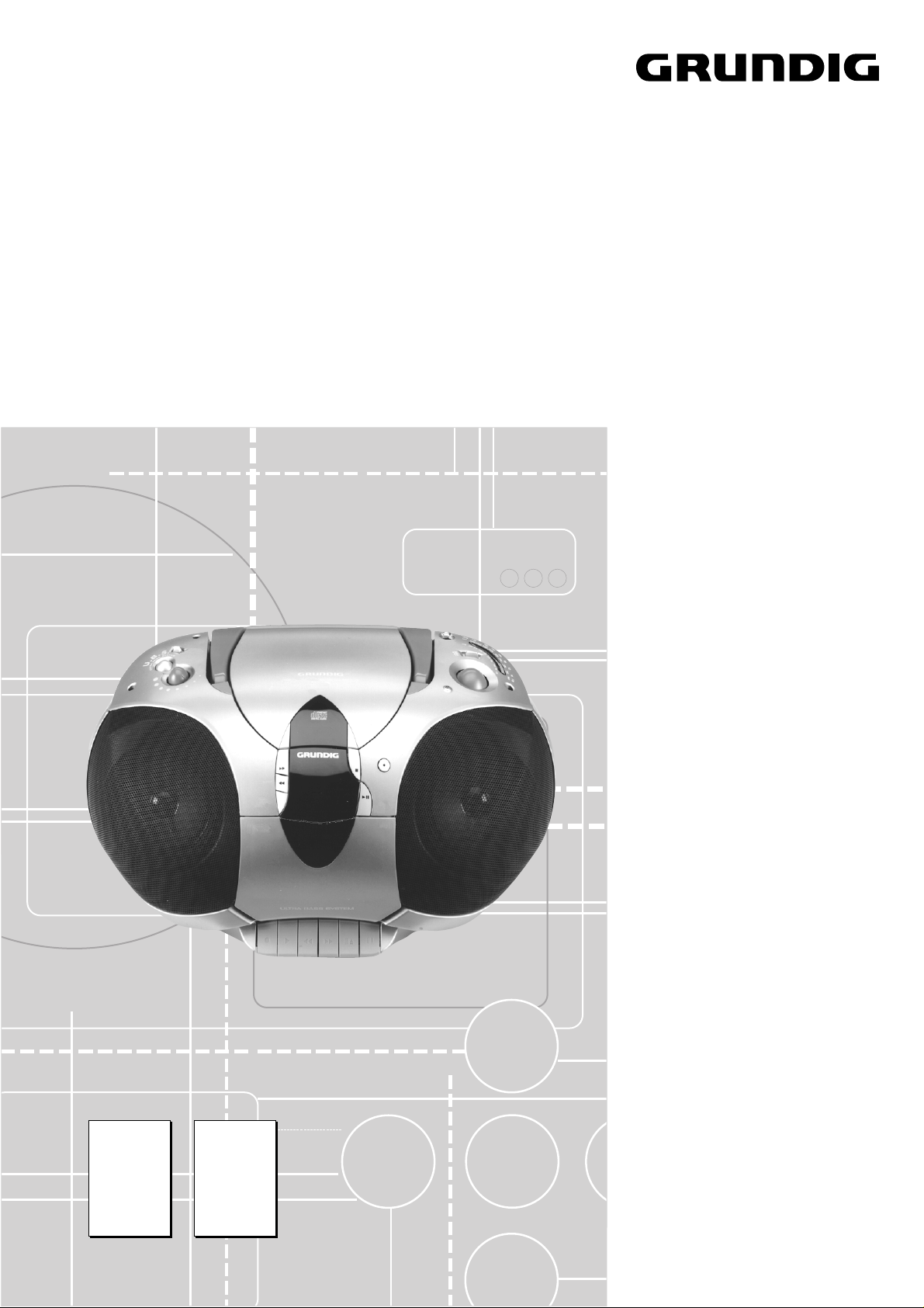
RR 630 CD
RR 630 CD / RR 660 CD Allgemeiner Teil / General Section
GRUNDIG Service 1 - 1
Service Manual
Audio
RR 630 CD
RR 660 CD
Zusätzlich erforderliche
Unterlagen für den Komplettservice
Additionally required
Service Documents for the Complete Service
Service
Manual
Service
Manual
Btx * 32700 #
Materialnummer
Part Number 72010 759 3000
Änderungen vorbehalten
Subject to alteration
Printed in Germany
VK211/232 0299
RR 630 CD
RR 660 CD
Materialnr. /Part No.
72010 759 3000
Sicherheit
Safety
Materialnr. /Part No.
72010 800 0000

1 - 2 GRUNDIG Service
Allgemeiner Teil / General Section RR 630 CD / RR 660 CD
Es gelten die Vorschriften und Sicherheitshin-
weise gemäß dem Service Manual "Sicherheit",
Materialnummer 72010 800 0000, sowie zusätz-
lich die eventuell abweichenden, landes-
spezifischen Vorschriften!
The regulations and safety instructions shall be
valid as provided by the "Safety" Service Manual,
part number 72010 800 0000, as well as the
respective national deviations!
Table of Contents
Page
General Note................................................1 - 2
General Section.............................. 1 - 3 … 1 - 8
Service Hints.............................................................................. 1 - 3
Technical Data ........................................................................... 1 - 3
Operating Instructions................................................................ 1 - 5
Disassembly Instructions ........................................................... 1 - 6
Adjustment Procedures..................2 - 3 ... 2 - 4
Layout of the PCBs
and Circuit Diagrams ................... 3 - 1 … 3 - 25
Wiring Diagram – RR 630 CD.................................................... 3 - 1
Wiring Diagram – RR 660 CD.................................................... 3 - 3
Block Diagram............................................................................ 3 - 5
Layout of the PCBs:
CD Servo Board ..................................................................... 3 - 6
Tuner Board, Stereo LED Board, CD LED Board ................ 3 - 11
Main Board ........................................................................... 3 - 12
Function Board – RR 630 CD .............................................. 3 - 15
Function Board – RR 660 CD .............................................. 3 - 17
Key Board – RR 630 CD ...................................................... 3 - 19
Key Board – RR 660 CD ...................................................... 3 - 20
Volume Board ...................................................................... 3 - 21
Rectifier Board, Headphone Board ...................................... 3 - 22
Circuit Diagrams:
CD Part .................................................................................. 3 - 7
Tuner Part .............................................................................. 3 - 9
AF Part ................................................................................. 3 - 13
Function Board – RR 630 CD .............................................. 3 - 15
Function Board – RR 660 CD .............................................. 3 - 17
Key Board – RR 630 CD ...................................................... 3 - 19
Key Board – RR 660 CD ...................................................... 3 - 20
Volume Board ...................................................................... 3 - 21
Rectifier Board, Headphone Board ...................................... 3 - 22
IC Block Diagrams ................................................................... 3 - 23
Spare Parts Lists and
Exploded Views.............................. 4 - 1 … 4 - 5
Inhaltsverzeichnis
Seite
Allgemeiner Hinweis ................................... 1 - 2
Allgemeiner Teil ............................. 1 - 3 … 1 - 8
Service-Hinweise ....................................................................... 1 - 3
Technische Daten ...................................................................... 1 - 3
Bedienhinweise.......................................................................... 1 - 4
Ausbauhinweise......................................................................... 1 - 6
Abgleichvorschriften ......................2 - 1 ... 2 - 2
Platinenabbildungen
und Schaltpläne ........................... 3 - 1 … 3 - 25
Verdrahtungsplan – RR 630 CD ................................................ 3 - 1
Verdrahtungsplan – RR 660 CD ................................................ 3 - 3
Blockdiagramm .......................................................................... 3 - 5
Platinenabbildungen:
CD-Servo-Platte ..................................................................... 3 - 6
Tuner-Platte, Stereo-LED-Platte, CD-LED-Platte ................ 3 - 11
Hauptplatte ........................................................................... 3 - 12
Funktionsplatte – RR 630 CD .............................................. 3 - 15
Funktionsplatte – RR 660 CD .............................................. 3 - 17
Bedienplatte – RR 630 CD................................................... 3 - 19
Bedienplatte – RR 660 CD................................................... 3 - 20
Lautstärkeplatte.................................................................... 3 - 21
Gleichrichterplatte, Kopfhörerplatte...................................... 3 - 22
Schaltpläne:
CD-Teil ................................................................................... 3 - 7
Tuner-Teil ............................................................................... 3 - 9
NF-Teil ................................................................................. 3 - 13
Funktionsplatte – RR 630 CD .............................................. 3 - 15
Funktionsplatte – RR 660 CD .............................................. 3 - 17
Bedienplatte – RR 630 CD................................................... 3 - 19
Bedienplatte – RR 660 CD................................................... 3 - 20
Lautstärkeplatte.................................................................... 3 - 21
Gleichrichterplatte, Kopfhörerplatte...................................... 3 - 22
IC-Blockdiagramme ................................................................. 3 - 23
Ersatzteillisten und
Explosionszeichnungen ................ 4 - 1 … 4 - 5
Allgemeiner Hinweis
Meßgeräte
Beachten Sie bitte das GRUNDIG Meßtechnik-Programm, das Sie
unter folgender Adresse erhalten:
General Note
Test Equipment
Please note the GRUNDIG Catalog "Test and Measuring Equipment"
obtainable from:
Grundig AG Geschäftsbereich Instruments Test- und Meßsysteme
Würzburger Str. 150, D-90766 Fürth
Tel.: 0911 / 703-4118, Fax: 0911 / 703-4130
eMail: instruments@grundig.de, Internet: http://www.grundig-instruments.de

GRUNDIG Service 1 - 3
Allgemeiner Teil / General SectionRR 630 CD / RR 660 CD
Technische Daten
Spannungsversorgung:
Netzbetrieb ............................................................... 230V, 50/60Hz
Batteriebetrieb ................................................. 8 x 1,5V (R20, UM1)
Verstärkerteil:
Ausgangsleistung (DIN 45324, 10% THD):
Musikleistung ................................................................ 2 x 4500mW
Sinusleistung................................................................. 2 x 2500mW
Stereo-Kopfhörer-Klinkenbuchse ........................................ 3,5mm ø
Rundfunkteil:
Wellenbereiche ....................................................FM 87,5 - 108MHz
MW 522 - 1620kHz
LW 150 - 285kHz
Zwischenfrequenzen ....................................... 10,7MHz und 465kHz
Antennen.................................................... Teleskopantenne für FM
eingebaute Ferritstab-Antenne für MW/LW
Cassettenteil:
Tonträger ..................................Compact-Cassette nach DIN 45516
Spurlage.......................................................Viertelspur international
Bandgeschwindigkeit .....................................................4,76cm/sec.
Motor ..................................................................... Gleichstrommotor
Frequenzübertragungsbereich ..................................... 125Hz - 8kHz
Geräuschspannungsabstand .................................................... 42dB
Gleichlauffehler ....................................................................... 0,35%
Automatik ...........................Aussteuerungsautomatik bei Aufnahme,
Automatisches Auslösen der Tasten am Bandende
CD-Teil:
Frequenzübertragungsbereich ..................................... 20Hz - 20kHz
Geräuschspannungsabstand .................................................... 65dB
Technical Data
Power Supply:
Mains operation ........................................................ 230V, 50/60Hz
Battery operation ............................................. 8 x 1.5V (R20, UM1)
Amplifier Section:
Output power (DIN 45324, 10% THD):
Music power ................................................................. 2 x 4500mW
Nominal power.............................................................. 2 x 2500mW
Jack socket for stereo headphones ................................... 3.5mm ø
Radio Section:
Waveband ............................................................ FM 87.5 - 108MHz
MW 522 - 1620kHz
LW 150 - 285kHz
Intermediate frequencies ................................10.7MHz and 465kHz
Aerials ......................................................... Telescopic aerial for FM
Built in ferrite rod aerial for MW/LW
Cassette Section:
Cassette........................................ Compact cassette to DIN 45516
Track System............................................International quartertrack
Tape Speed ................................................................... 4.76cm/sec.
Motor.................................................................................. DC motor
Frequency Range ........................................................125Hz - 8kHz
S/N Ratio (weighted) ................................................................ 42dB
Wow and Flutter ..................................................................... 0.35%
Automatic..................................... Automatic recording level control
Automatic button release at tape end
CD Section:
Frequency range .........................................................20Hz - 20kHz
S/N ratio, weighted ................................................................... 65dB
Laseranschlußplatte
Laser PCB
Schutzlötstelle
protective soldered joint
Allgemeiner Teil
Service-Hinweise
Cassettenteil
Überprüfen Sie vor Beginn der Service-Arbeiten, ob die Magnetköpfe,
die Tonwelle und die Gummiandruckrolle frei von Bandabrieb sind.
Zum Reinigen dieser Teile verwenden Sie ein mit Spiritus oder Reini-
gungsbenzin getränktes Wattestäbchen; dadurch verbessert sich der
Aufnahme- und Wiedergabepegel, sowie der Bandlauf.
Nach dem Ersatz von Magnetköpfen oder sonstiger Bauteile müssen
die technischen Daten des Gerätes anhand der im Service Manual
vorgegebenen Meßwerte überprüft bzw. eingestellt werden.
CD-Teil
Bei Ausbau der CD-Lasereinheit muß vor Abziehen der Steck-
verbindungen eine Schutzlötstelle auf der Leiterplatte der
Lasereinheit angebracht werden, um eine Zerstörung der Laser-
diode durch statische Aufladung zu vermeiden.
Beim Einbau einer neuen Lasereinheit (CD-Laufwerk) muß nach
Einstecken der Steckverbinder die werkseitig angebrachte
Schutzlötstelle entfernt werden!
General Section
Service Hints
Cassette Section
Before commencing service work, ensure that the magnetic heads, the
capstan and the pinch roller are free from particles produced by tape
abrasion. The recording and playback levels and the tape run can be
improved by cleaning these parts with a cotton-wool tip soaked in spirit
or cleaning benzine.
If the heads or other components have been replaced, the technical
data of the recorder must be checked or adjusted according to the
values specified in the Service Manual.
CD Section
When removing the Laser pick-up, the Laser pick-up PCB must be
provided with a protective soldered joint before unplugging the
connectors to avoid damage to the Laser diode by static charges.
When inserting the new Laser pick-up (CD drive mechanism) the
soldered joint fitted at the factory must be removed after the
connectors are plugged in.
Allgemeiner Teil / General Section RR 630 CD / RR 660 CD
1 - 4 GRUNDIG Service
Bedienhinweise
Hinweis: Dieses Kapitel enthält Auszüge aus der Bedienungsanleitung. Weitergehende Informationen entnehmen Sie
bitte der gerätespezifischen Bedienungsanleitung, deren Materialnummer Sie in der entsprechenden Ersatzteilliste finden.
CD
R-SKIP Q –
zum Überspringen von Stücken
und zum Suchen in
Rückwärtsrichtung
F-SKIP R –
zum Überspringen von Stücken
und zum Suchen in Vorwärts-
richtung
REPEAT –zum Wiederholen eines
Titels/aller Titel
STOP 9 –
zum Stoppen der Wiedergabe
PLAY/PAUSE 2;– zum Starten/Unterbrechen der
Wiedergabe
PROG. –zum Programmieren von Titeln
im Speicher
REPEAT
6 –leuchtet wenn ein Titel
Wiederholt wird und blinkt
wenn alle Titel wiederholt
werden.
PLAY/PAUSE
6 – Leuchtet während CD-Wieder-
gabe und blinkt wenn die
Wiedergabe unterbrochen wird
(PAUSE).
Cassette
0 –Starten der Aufnahme
B –Starten der Wiedergabe
Q –schneller Rücklauf
R –schneller Vorlauf
9//
–Stoppen des Bandlaufs und
Öffnen des Cassettenfacks
; –unterbrechen/fortsetzen der
Wiedergabe/Aufnahme
Rückseite
Batteriefach:
– für 8 Monozellen, Typ R20,
UM1 oder D
AC ~: –Netzanschlußbuchse.
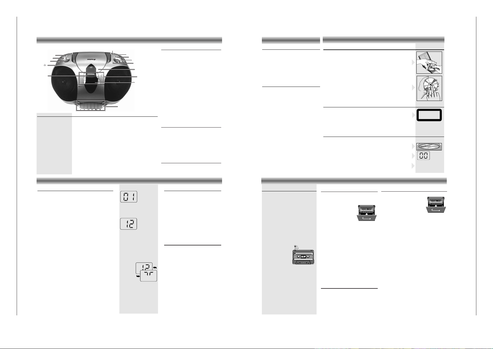
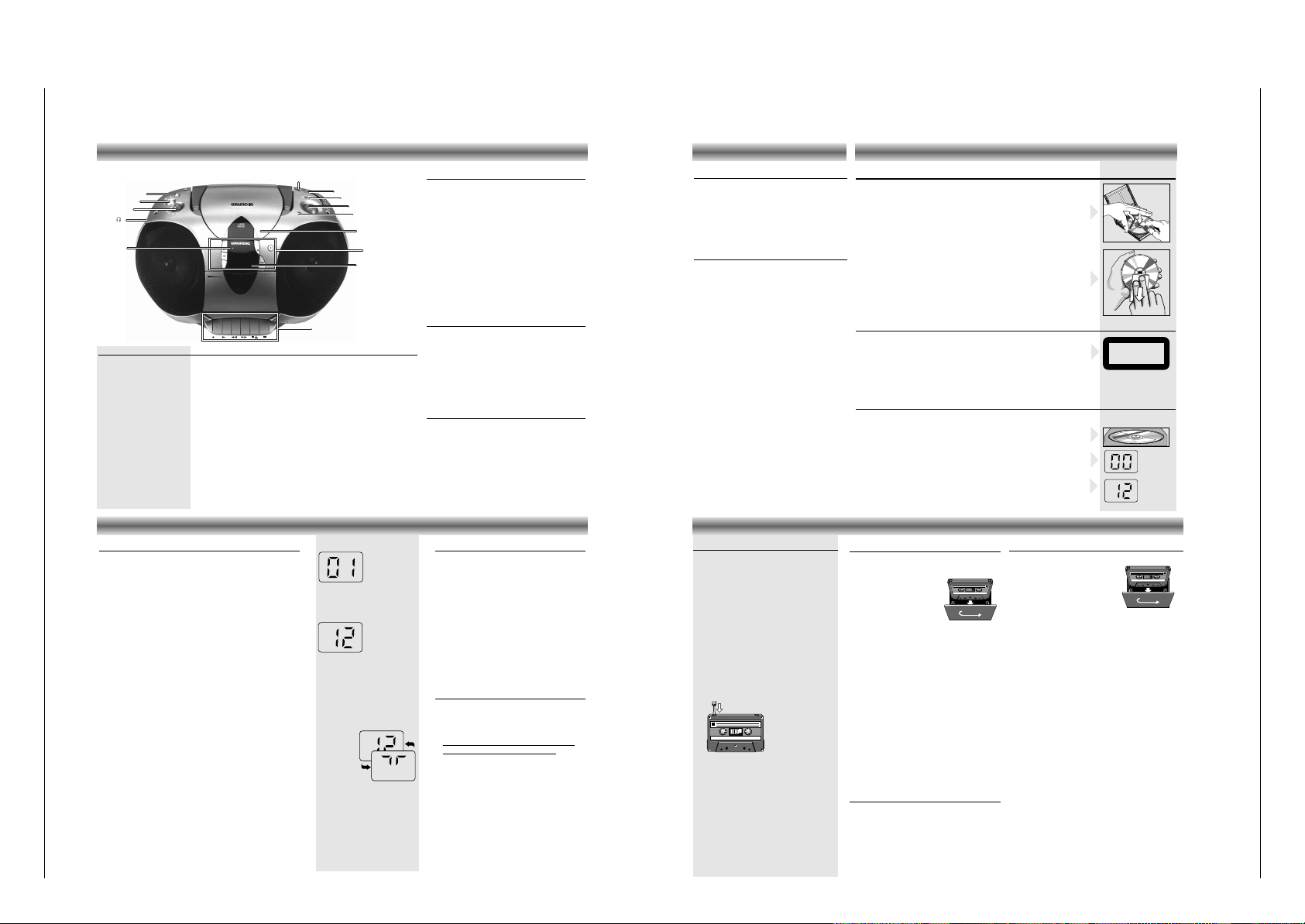
BEDIENELEMENTE
Ober- und Vorderseite
ON 6 – leuchtet auf, wenn das Gerät eingeschaltet ist
p – Buchse für Stereo-Kopfhörer
VOLUME – zum Einstellen der Lautstärke
UBS – ein/aus des U
LTRA BASS SYSTEM
FUNCTION – CD: zum Umschalten auf CD-Betrieb/Einschalten
– TAPE/OFF: zum Umschalten auf Cassettenbetrieb/Ausschalten
– RADIO: zum Umschalten auf Radiowiedergabe/Einschalten
ANTENNA – Teleskopantenne für FM-Empfang
SCALE – Abstimmskala
BAND – zum Wählen zwischen FM, MW, und LW
TUNING – zum Abstimmen auf einen Radiosender
FM STEREO 6 – leuchtet auf, wenn ein UKW-Stereo-Sender empfangen wird
OPEN/CLOSE – zum Öffnen und Schließen der CD-Deckels
REMOTE SENSOR – zur Empfangen der Fernbediensignale
(nur RR 660 CD)
ANTENNA
FM STEREO
TUNING
F-SKIP
R-SKIP
REPEAT
STOP
PLAY/
PAUSE
PROG
TAPE DIRECTION
VOL
FM
MW
LW
RR 630 CD
RADIO CASSETTE RECORDER WITH CD
CD
TAPE/OFF
RADIO
CASSETTE
FUNCTION
U.B.S.
VOLUME
ANTENNA
SCALE
BAND
TUNING
FM STEREO 6
OPEN/CLOSE
CD
TRACK
ON
ON 6
REMOTE SENSOR
RADIO
Radioantennen
– Bei UKW-Empfang (FM) die Teleskopantenne
herausziehen und durch Neigen und Drehen
ausrichten. Bei zu starkem UKW-Signal (in
Sendernähe) empfiehlt es sich die Antenne
einzuschieben.
– Für
MW/LW-E
mpfang hat das Gerät eine ein-
gebaute Antenne. Die Teleskopantenne kann
also eingeschoben bleiben. Zum Ausrichten
der Antenne das ganze Gerät drehen.
Rundfunkempfang
• Den FUNCTION-Schalter auf RADIO stellen.
– Die Einschaltanzeige ON 6 leuchtet auf.
• Den Ton mit den Reglern VOLUME und UBS
einstellen.
• Sie können einen Stereo-Kopfhörer mit
3,5 mm
Stecker an die Buchse p anschließen.
– Die Lautsprecher werden damit abgeschaltet.
• Den Wellenbereich mit dem BAND-Schalter
wählen.
• Mit dem TUNING-Knopf auf den Sender
abstimmen.
– Wenn die Anzeige FM STEREO
6 erscheint,
empfangen Sie einen UKW-Stereo-Sender.
• Das Gerät ist ausgeschaltet, wenn sich der
FUNCTION-Wahlschalter in der Position
TAPE/OFF befindet und keine Tasten gedrückt
sind.
– Die Einschaltanzeige ON 6 erlischt.
CD-SPIELER
Umgang mit CDs
• Nur digitale Audio-CDs verwenden. ( + )
• Um die CD aus der Box herauszunehmen, drücken Sie beim Anheben
der CD gegen die Mittenachse.
• Die CD niemals beschriften oder mit einem Aufkleber versehen.
• Fassen Sie die CD immer am Rande an und legen Sie sie immer in die
Box zurück.
• Zum Reinigen die CD anhauchen und mit einem weichen, nichtfasernden
Tuch geradlinig von der Mitte aus in Richtung des Randes abwischen.
Reinigungsmittel können die CD beschädigen!
• Schützen Sie die CDs vor Regen und Feuchtigkeit, vor Sand und vor
Hitze z.B. von Heizgeräten oder im Innenraum von in der Sonne
geparkten Autos.
OIOIOI OI OIOIOI OIOIOIOI
OIOI OIOIOIOI OIOI
OIOIOO OIOI
OIOI OIOIO OIOI
OIOIOIOOIO OIOI OI
CLASS 1
LASER PRODUCT
6. OYE MI CANTO (Hear My Voice)
7. DON'T W
ANNA LOSE YOU
8. GET ON YO
UR FEET
9. YOUR LOVE IS BED FOR ME
10. CUTS BOTH W
AYS
11. OYE MI CANTO (Spanish Version)
12. SI VOY A PERDERTE
EPC 465145 2
BIEM/STEMRA
STEREO
A
ll rig
h
ts
o
f th
e
p
ro
d
u
c
e
r a
n
d
o
f th
e
o
w
n
e
r o
f th
e
re
c
o
rd
e
d
w
o
rk
re
s
e
rv
e
d
. U
n
a
u
th
o
ris
e
d
c
o
p
y
in
g
,
p
u
b
lic
p
e
rfo
rm
a
n
c
e
, b
ro
a
d
c
a
stin
g
, h
irin
g
o
r ren
ta
l o
f th
is
re
c
o
rd
in
g
p
ro
h
ib
ite
d
. M
a
d
e
in
A
u
s
tria
1. AY, AY, I
2. HERE WE ARE
3. SAY
4. THINK ABOUT YOU NOW
5. NOTHIN' NEW
C
O
M
P
A
C
T
D
IG
IT
A
L
A
U
D
IO
1
2
Warnung
CLASS 1 LASER PRODUCT bedeutet, daß der Laser wegen seines
technischen Aufbaus eigensicher ist, so daß der maximal erlaubte
Ausstrahlwert unter keinen Umständen überschritten werden kann.
VORSICHT: Wenn andere als die hier spezifizierten Bedienungs-
einrichtungen benutzt oder andere Verfahrensweisen ausgeführt werden,
kann es zu gefährlicher Strahlungsexposition kommen.
Einlegen einer CD
• Den FUNCTION-Schalter auf CD stellen.
– Die Einschaltanzeige ON 6 leuchtet auf.
• Zum Öffnen des Deckels auf OPEN/CLOSE drücken.
• Die CD mit der bedruckten Seite nach oben einlegen.
• Den Deckel schließen.
– Der CD-Spieler startet und tastet die Inhaltsangabe der CD ab.
Danach erscheint die Anzahl der Titel.
CD-SPIELER
Abspielen einer CD
•
Zum Starten des Abspielens auf PLAY/PAUSE 2;
drücken.
– Sobald das Abspielen beginnt, leuchtet die Anzeige
PLAY/PAUSE 6 und erscheint die Nummer des laufenden
Stücks.
• Den Ton mit den Reglern VOLUME und UBS
einstellen.
• Für kurzzeitige Unterbrechungen auf PLAY/PAUSE 2; drücken.
– Die Anzeige PLAY/PAUSE 6 fängt an zu blinken
• Zum Fortsetzen der Wiedergabe die Taste PLAY/PAUSE 2;
erneut drücken.
• Zum Stoppen auf STOP 9 drücken.
– Das Display zeigt die Anzahl der Titel auf der CD.
–
Der CD-Spieler geht ebenfalls in Stellung STOP:
– wenn das Ende der CD erreicht wird;
– wenn die Batterien ausgehen oder bei anderen
Stromunterbrechungen.
•
Z
um Herausnehmen der CD öffnen Sie den Deckel durch Drücken
auf die rechte vordere Ecke des CD Deckels (OPEN/CLOSE).
• Den CD-Deckel erst öffnen wenn sich der CD-Spieler in
Stellung STOP befindet.
Wahl eines anderen Titels während der Wiedergabe
•
Taste R-SKIP Q oderF-SKIP R drücken, bis die Nummer
des
gewünschten Titels im Anzeigefeld erscheint.
– Die Wiedergabe wird unterbrochen, und kurz danach beginnt
die Wiedergabe des gewählten Stücks.
Beginnen mit einem bestimmten Titel
•
Taste R-SKIP Q oderF-SKIP R drücken, bis die Nummer
des
gewünschten Titels im Anzeigefeld erscheint.
• Die Wiedergabe beginnt automatisch beim Titel mit der
gewählten Nummer
Rasches Suchen einer Passage
•
R-SKIP Q
gedrückt halten, um in Richtung Plattenanfang zu
suchen.
•
F-SKIP R
gedrückt halten, um in Richtung Plattenende zu suc-
hen.
Hinweis:
Dies ist ein 'hörbares Suchen'.
Während des Suchens wird die Lautstärke reduziert und nach
dem Loslassen der Taste wird die
Lautstärke auf ihren normalen
Wert zurückgestellt.
Wiederholfunktion
Wiederholung eines Titels
•
Vor oder während der Wiedergabe Taste
REPEAT drücken.
– Die Anzeige REPEAT 6 leuchtet auf; der Titel
wird jetzt ständig wiederholt
• Taste REPEAT
zweimal
drücken, um die
Wiederholung zu beenden
Wiederholung der CD
• Vor oder während der Wiedergabe Taste
REPEAT
zweimal
drücken.
– Die Anzeige REPEAT 6 fängt an zu blinken;
die CD wird jetzt ständig wiederholt
• Taste REPEAT erneut drücken, um die
Wiederholfunktion zu beenden
Random
(nur RR 660 CD über Fernbedienung)
• Drücken Sie während der Wiedergabe
dreimal die Taste MODE
auf der
Fernbedienung
.
– Die Musiktitel werden in zufälliger Reihenfolge
abgespielt, bis jeder Titel einmal gespielt
wurde.
– Die Displayanzeige wechselt zwischen der
Titelnummer und einer laufenden Symbolfolge.
• Die Funktion wird beendet, wenn Sie die
Taste STOP 9 (die Wiedergabe wird
gestoppt) oder MODE drücken; in diesem Fall
werden die nachfolgenden Stücke in
gewohnter Reihenfolge wiedergegeben.
•
Die Funktion 'RANDOM' ist nicht möglich,
solange
Sie ein Programm abspielen.
CASSETTENDECK
Compact-Cassetten
– Kopierrechte: Eine Aufnahme ist nur im
Rahmen der Urheberrechte oder anderer
Rechte Dritter zulässig.
• Verwenden Sie für die Aufnahme nur
NORMAL-
Cassetten (IEC I), bei denen die
Laschen nicht herausgebrochen sind.
– Das Gerät ist nicht geeignet zum Aufnehmen
auf CHROME (IEC II) oder METAL (IECIV)
Cassetten.
• Für die Wiedergabe können Sie jedoch
jeden Cassettentyp einsetzen.
–
Direkt am Anfang des Bandes erfolgt
während der ersten 7 Sekunden, wenn das
Vorspannband
vorbeiläuft, keine Aufnahme.
• Sie können eine Aufnahme vor unbeabsich-
tigtem Löschen
schützen:
halten Sie
die zu schützen
den
Cassettenseite auf sich
zugerichtet und
brechen Sie die
Lasche links oben
heraus. Jetzt läßt sich diese Seite nicht mehr
neu bespielen.
• Zum Aufheben dieser Löschsperre decken
Sie die Öffnung mit einem Stück Klebeband
ab.
• Schützen Sie die Cassetten vor Regen und
Feuchtigkeit, vor Sand und vor Hitze z.B.
von Heizgeräten oder im Innenraum von in
der Sonne geparkten Autos.
• Vermeiden Sie das Aufbewahren der
Cassetten in der Nähe starker Magnetfelder
(z.B. Fernsehgeräte, Lautsprecherboxen,
Motoren etc.).
1
Cassettenwiedergabe
• Den FUNCTION-Schalter auf TAPE/OFF
stellen.
• Öffnen Sie das Cassettenfach mit 9//.
•
Legen Sie eine bespielte
Cassette mit der offenden
Bandseite nach unten und
der vollen Spule links ein.
• Den Ton mit den Reglern
VOLUME und UBS ein-
stellen.
• Sie können einen Stereo-Kopfhörer mit
3,5 mm
Stecker an die Buchse p anschließen.
– Die Lautsprecher werden damit abgeschaltet.
• Zum Starten des Abspielens auf B drücken.
– Am Bandende stoppt die Wiedergabe.
• Für kurzzeitige Unterbrechungen auf
;
drücken.
– Erneut auf ; drücken, wenn die Wiedergabe
fortgesetzt werden soll.
• Zum Stoppen auf 9// drücken.
– Am Bandende wird die B-Taste entriegelt.
– Das Gerät ist ausgeschaltet, wenn sich der
FUNCTION-Wahlschalter in der Position
TAPE/OFF befindet und keine Tasten gedrückt
sind.
– Die Einschaltanzeige ON
6 erlischt.
Schneller Vor- und Rücklauf
• Drücken Sie R, um vorwärts bis an das
Ende des Bandes zu spulen.
• Drücken Sie Q, um rückwärts bis an den
Anfang des Bandes zu spulen.
• Zum Stoppen auf 9// drücken.
Aufnahme
• Öffnen Sie das Cassettenfach mit 9//.
• Legen Sie eine Cassette ein.
• Beim Mithören der Aufnahme, den
Ton mit den Reglern VOLUME und
UBS einstellen.
Die Stellungen dieser Regler haben
keinen Einfluß auf die Aufnahme.
• Zum Aufnahmestart auf 0 drücken (die Taste B rastet
automatisch mit ein).
– Wenn das Bandende erreicht ist, werden die
Recorder-Tasten automatisch entriegelt.
•
Zum Unterbrechen der Aufnahme die Taste ; drücken.
•
Zum Fortsetzen der Aufnahme die Taste ; erneut drücken.
• Die Taste 9// drücken, wenn die Aufnahme vor Er-
reichen des Bandendes gestoppt werden soll. Durch er-
neutes Drücken dieser Taste öffnet sich das Cassettenfach.
• Das Gerät ist ausgeschaltet, wenn sich der
FUNCTION-Wahlschalter in der Position TAPE/OFF
befindet und keine Laufwerktasten gedrückt sind. Die
Einschaltanzeige ON 6 erlischt.
CD Synchro – Aufnahme vom CD-Spieler
• Den FUNCTION-Schalter auf CD stellen.
• Sie brauchen den CD-Spieler nicht separat zu starten:
sobald Sie auf 0 drücken, startet der CD-Spieler
automatisch.
– Steht der CD-Spieler in Stellung STOP, startet die
Aufnahme vom Anfang der CD (oder vom Anfang des
gespeicherten Programms).
•
Um eine Aufnahme in der Mitte eines Stücks zu starten,
beginnen Sie die CD-Wiedergabe wie gewohnt.
• Sobald die gewünschte Passage erreicht ist, drücken
Sie auf Pause und anschließend auf 0, um die
Aufnahme zu starten.
Aufnahme vom Radio
• Den FUNCTION-Schalter auf RADIO stellen.
• Mit dem BAND-Schalter den Wellenbereich wählen.
• Mit dem TUNING-Knopf auf den gewünschten
Radiosender abstimmen.
• Zum Aufnahmestart auf 0 drücken.
RR 630 CD / RR 660 CD Allgemeiner Teil / General Section
Operating Instructions
Note: This chapter contains excerpts from the operating instructions. For further particulars please refer to the
appropriate user instructions the part number of which is indicated in the relevant spare parts list.
GRUNDIG Service 1 - 5
CD Control
R-SKIP Q – to skip and search backward
F-SKIP R – to skip and search forward
REPEAT – to repeat one/all tracks
STOP 9 – to stop playback
PLAY/PAUSE 2; – to start and interrupt playback
PROG. – to programme track numbers
in the memory
REPEAT
6 – lights up when repeat one
function is on, blinks when
repeat all function is on.
PLAY/PAUSE
6 – lights up during CD
playback, blinks during CD
pause mode.
Cassette Control
0 – to start recording
B – to start cassette playback
Q – fast rewind
R – fast forward
9// – to stop and eject the cassette
; –
to interrupt/continue
playback/recording
Back panel
Battery compartment:
– for inserting 8 batteries
type R20, UM1 or D-cells.
AC ~ – Socket for mains lead.
Top and front panel
ON 6 – lights up when the unit is on
p – connection for headphones
VOLUME – to adjust the volume
UBS – to switch the ULTRA BASS SYSTEM on and off
FUNCTION – CD: to switch to CD mode / Power On
– TAPE/OFF: to switch to TAPE mode / Power Off
– RADIO: to switch to RADIO mode / Power On
ANTENNA – telescopic aerial for FM reception
SCALE – tuning dial scale
BAND – to select between FM, MW, and LW waveband
TUNING – to tune to a radio station
FM STEREO
6 – lights up when receiving FM stereo stations
OPEN/CLOSE – to open and close the CD door
REMOTE SENSOR – to receive the remote signals
(only RR 660 CD)
Radio aerials
– For FM, pull out the telescopic aerial. To im-
prove FM-reception, incline and turn the aerial.
Reduce its length if the FM-signal is too strong
(very close to a transmitter).
– For MW/LW, the set is provided with a built-in
aerial, so the telescopic aerial is not needed.
Direct the aerial by turning the whole set.
Radio reception
• Set the FUNCTION switch to RADIO.
– The ON indicator 6 lights up.
• Adjust the sound using the VOLUME and UBS
controls.
• You may connect stereo headphones having a
3.5 mm plug to the jack p.
– Inserting the plug will disconnect the speakers.
• Select the wave band using the BAND
selector.
• Tune to a desired radio station using the
TUNING control.
– When the indicator FM STEREO 6 appears,
you are receiving an FM stereo transmitter.
• The set is switched off when the FUNCTION
switch is in the TAPE/OFF position and no
buttons are pressed.
–The ON indicator 6 goes out.
CD PLAYER
CD handling
• Use only Digital Audio CDs which have the symbol
+
.
• To take the CD out of its box easily, press the centre spindle while lifting
the CD.
• Never write on a CD or attach any sticker to the CD.
• Always hold the CD at the edge and always store it in its box after use
with the label facing up.
• To remove dust and dirt, breathe on the CD and wipe it with a soft, lint-
free cloth in a straight line from the center towards the edge. Cleaning
agents may damage the CD.
• Do not expose the CD to rain, moisture, sand, or to excessive heat. (E.g.
from heating equipment or in motor cars parked in the sun).
OIOIOI OI OIOIOI OIOIOIOI
OIOI OIOIOIOI OIOI
OIOIOO OIOI
OIOI OIOIO OIOI
OIOIOIOOIO OIOI OI
CLASS 1
LASER PRODUCT
6. OYE MI CANTO (Hear My Voice)
7. DON'T WANNA LOSE YOU
8. GET ON YOUR FEET
9. YOUR LOVE IS BED FOR ME
10. CUTS BOTH W
AYS
11. OYE M
I CANTO (Spanish Version)
12. SI VOY A PERDERTE
EPC 465145 2
BIEM/STEMRA
STEREO
A
ll rig
h
ts
o
f th
e
p
ro
d
u
c
e
r a
n
d
o
f th
e
o
w
n
e
r o
f th
e
re
c
o
rd
e
d
w
o
rk
re
se
rv
e
d
. U
n
a
u
th
o
rise
d
c
o
p
y
in
g
,
p
u
b
lic
p
e
rfo
rm
a
n
c
e
, b
ro
a
d
c
a
stin
g
, h
irin
g
o
r re
n
ta
l o
f th
is rec
o
rd
in
g
p
ro
h
ib
ite
d
. M
a
d
e
in
A
u
s
tria
1. AY, AY, I
2. HERE WE ARE
3. SAY
4. THINK ABOUT YO
U NOW
5. NOTHIN' NEW
C
O
M
P
A
C
T
D
IG
IT
A
L
A
U
D
I
O
1
2
Warning
CLASS 1 LASER PRODUCT means that the laser´s construction makes it
inherently safe so that the legally prescribed maximum permissible ratiation
values can never be exceeded.
CAUTION: Using any equipment or devices other than those described and
specified in these operating instructions, or tampering with the unit in any
way, can result in dangerous exposure to radiation.
Inserting a CD
• Set the FUNCTION switch to CD.
– The ON indicator 6 lights up.
• Press OPEN/CLOSE to open the CD door.
• Insert the AUDIO CD, printed side facing up.
• Close the cover.
– TheCD-playerscans the contents list of the CD.
After that, the total number of tracks appears on the display.
Playing a CD
• Press PLAY/PAUSE 2; to start playback.
– The PLAY/PAUSE 6 indicator will light up and the display
shows the track number.
•A
djust the sound using the VOLUME and UBS controls.
• For brief interruptions, press PLAY/PAUSE 2;.
– The PLAY/PAUSE 6 indicator starts blinking
• To resume playback, press PLAY/PAUSE 2; again.
• To stop playback, press STOP 9.
– The total number of tracks will appear on the display.
– The CD player also goes to position STOP:
– when the end of the CD is reached;
– if the batteries run down or if the power supply is interrupted.
• To take out the CD, open the CD door by pressing
OPEN/CLOSE.
•
Open the CD door only if the CD-player is in position STOP.
Selecting another track during play
• Press R-SKIP Q or F-SKIP R several times until the
required track number appears in the display.
– The selected track begins to play.
Starting with a particular track
• Press R-SKIP Q or F-SKIP R until the required track
number appears in the display.
– Play starts automatically from the selected track.
Searching for a passage during play
• Hold R-SKIP Q down to search backwards to the
beginning.
•
Hold F-SKIP R down to search forwards to the end.
Note: This function can be described as “audibly” searching
for a
title. During the search, volume is reduced and returns
to its
adjusted level as soon as the button is released.
Repeat function
Repeating a track
• Press REPEAT before or during playback.
– The REPEAT 6 indicator lights up.
– The track will now be repeated continuously
• Press REPEAT
twice
to stop the track being
repeated.
Repeating the CD
• Press REPEAT
twice
before or during
playback.
– The REPEAT 6 indicator starts blinking.
– The CD will now be repeated continuously
• To switch the repeat mode off, press REPEAT
again.
Random function
(only RR 660 CD via remote control)
• During playback, press the MODE button
on
the remote control three times
.
– The tracks are played in random order until all
of them have been played once.
– The display indication toggles between the
track number and a moving symbol.
• The function is deactivated by pressing
STOP 9 (in which case the CD stops) or
MODE again; in this case the remaining tracks
are played in their normal order.
• The random function is not possible during
playback of a programme.
Compact cassettes
– Copyright: Recording is permissible insofar
copyright or other rights of third parties are
not infringed.
• For recording, use a NORMAL (IEC type I)
cassette on which the tabs are not broken
out.
– This deck is not suited for recording on
CHROME (IEC II) or METAL (IECIV)
cassettes.
• For playback, any cassette type may be in-
serted.
– At the very beginning and end of the tape,
no recording will take place during the
7 seconds when the leader tape passes the
recorder heads.
• To prevent the acciden-
tal erasure of a recor-
ding, keep the
cassette side to be
safeguarded in
front of you and
break out the left
tab. Now, recording on this side is no
longer possible.
• To render this safeguard ineffective, cover
the hole with a piece of adhesive tape.
• Do not expose the cassettes to rain,
moisture, sand, or to excessive heat. (E.g.
from heating
equipment or in motor cars
parked in the sun).
• Do not store cassettes near strong magnetic
fields (for example, TV sets, speakers,
engines, etc.).
1
Cassette playback
• Set the FUNCTION switch to TAPE/OFF.
• Press 9// to open the cassette holder.
• Insert a recorded cassette.
with the open side
downward and the full
spool on the left.
• Adjust the sound using the
VOLUME and UBS
controls.
• You may connect stereo headphones having a
3.5 mm plug to the jack p.
– Inserting the plug will disconnect the speakers.
• Press B and playback will start.
– Playback stops when the tape in the deck
reaches the end.
• For brief interruptions, press
;.
– To restart playback, press this button once
more.
• To stop, press 9//.
– When the end of the tape is reached the B
button is released.
– The set will be switched off if the FUNCTION
switch is in position TAPE/OFF and no
buttons are pressed.
– The ON indicator
6 goes out.
Winding the tape
• Press R to search forward to the end of the
tape.
• Press Q to search backward to the
beginning of the tape.
• To stop, press 9//.
Cassette recording
• Press 9// to open the cassette holder.
• Insert the cassette.
• When monitoring during record-
ing, adjust the sound using the
controls VOLUME and UBS.
These controls do not affect the
recording.
• Start recording by pressing 0.
(the B button is automatically also pressed).
– When the end of the tape is reached, the recorder
buttons are released.
• To interrupt recording, press
;.
• To continue recording, press ; again.
• Press 9// if you want to stop recording before the
end of the tape.
On pressing again, the cassette holder will open.
• The set is switched off if the FUNCTION switch is in
position TAPE/OFF and no buttons are pressed.
– The ON indicator 6 goes out.
Recording from the CD-player (CD synchro recording)
• Set the FUNCTION switch to CD.
• It’s not necessary to start the CD player separately: by
pressing 0 the CD player starts automatically.
– If the CD player is in STOP position, recording will
start from the beginning of the CD (or from the
beginning of the programmed selection).
• To start a recording in the middle of a track, play the
CD in the normal way.
• As soon as the desired passage is reached, pause the
CD and then start recording by pressing 0.
Recording from the radio
• Set the FUNCTION selector to RADIO.
• Select the wave band using the BAND switch.
• Tune to desired radio station using the TUNING
control knob.
• Start recording by pressing 0.
CONTROLS
ANTENNA
FM STEREO
TUNING
F-SKIP
R-SKIP
REPEAT
STOP
PLAY/
PAUSE
PROG
TAPE DIRECTION
VOL
FM
MW
LW
RR 630 CD
RADIO CASSETTE RECORDER WITH CD
CD
TAPE/OFF
RADIO
CASSETTE
FUNCTION
U.B.S.
VOLUME
ANTENNA
SCALE
BAND
TUNING
FM STEREO 6
OPEN/CLOSE
CD
TRACK
ON
ON 6
REMOTE SENSOR
RADIO
CD PLAYER
CASSETTE DECK
Allgemeiner Teil / General Section RR 630 CD / RR 660 CD
1 - 6 GRUNDIG Service
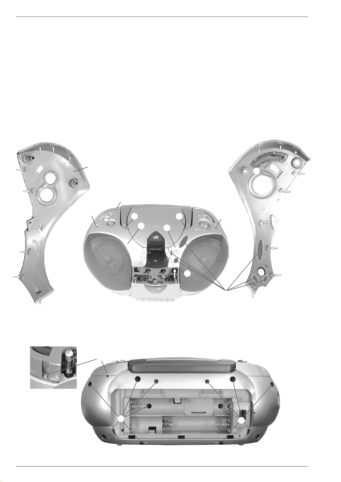
Ausbauhinweise
1. Gehäuserückwand abnehmen
- Deckel F abnehmen und darunter liegende Schraube entfernen
(Fig. 1).
- Schraube H und B herausdrehen (Fig. 1).
- Abdeckung E (Fig. 1) abnehmen:
Die Abdeckung wird durch Rastnasen gehalten und ist zusätzlich
an den markierten Stellen verklebt. Öffnen Sie die Cassettenfach-
klappe und hebeln Sie die Blende an der Stelle J beginnend in
Pfeilrichtung vorsichtig auf. Wenden Sie zuviel Kraft auf, können
Rastnasen oder die Blende brechen! In Fig. 2 sehen Sie die
Anordnung der Rastnasen.
- Schraube G und 12 Schrauben I herausdrehen (Fig. 4).
- Gehäusevorderteil und Gehäuserückteil vorsichtig ca. 5cm ausein-
anderziehen.
- Die Stecker CN101, CN901 und den Antennenanschluß P501
ziehen.
- Gehäusevorderteil und Gehäuserückteil auseinandernehmen.
Disassembly Instructions
1. Removing the Rear of the Cabinet
- Remove cover F and undo the screw below it (Fig. 1).
- Undo screw H and B (Fig. 1).
- Remove cover E (Fig. 1):
The cover is fixed by catches and additionally glued at the marked
positions. Open the cassette door and carefully level off the cover
at point J in the direction of the arrow. Be careful not to break the
cover or the catches. The catches are shown in (Fig. 2).
- Undo screw G and 12 screws I (Fig. 4).
- Pull the front and the rear of the cabinet carefully apart by an amount
of about 5cm.
- Unplug the connectors CN101, CN901 and detach the aerial
connection P501.
- Take the front and the rear of the cabinet apart.
B
A
C
D
E
F
G
H
J
I
I
G
E
D
Fig. 1
Fig. 2
Fig. 3
Fig. 4
Klebestellen
glued joints

RR 630 CD / RR 660 CD Allgemeiner Teil / General Section
GRUNDIG Service 1 - 7
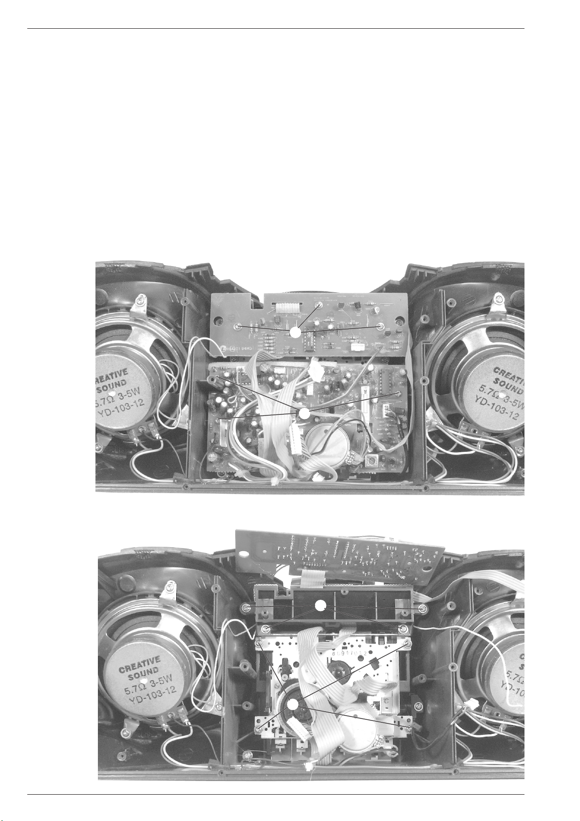
3. CD-Servo Platine ausbauen
- Gehäuserückwand abnehmen (siehe Pkt. 1).
- 2 Schrauben L herausdrehen (Fig. 6).
- Abschirmung hochbiegen und Schraube M herausdrehen.
- Platine herausnehmen, gegebenfalls Steckverbinder lösen.
- Sicherungslötstelle O (Fig. 7) des Lasers kurzschließen, dabei
Steckverbinder nach Bedarf öffnen.
3. Removing the CD Servo Circuit Board
- Remove the rear of the cabinet (see point 1).
- Undo 2 screws L (Fig. 6).
- Bend the protective screen up and undo screw M.
- Take the circuit board out; unplug the connectors if necessary.
- Short-circuit the safety solder tag O (Fig. 7) of the laser, unplug the
connector if necessary.
L
M
Fig. 6
O
Fig. 7
4. CD-Laufwerk ausbauen
- Gehäuserückwand abnehmen (siehe Pkt. 1).
- CD-Servo Platine ausbauen (siehe Pkt. 3).
- 4 Schrauben P herausdrehen (Fig. 8) und CD-Laufwerk heraus-
nehmen, dabei Steckverbinder nach Bedarf öffnen.
P
Fig. 8
4. Dismantling the CD Drive Mechanism
- Remove the rear of the cabinet (see point 1).
- Remove the CD Servo circuit board (see point 3).
- Undo 4 screws P (Fig. 8) and take the CD drive mechanism out;
unplug the connector if necessary.
K
2. Gehäuseoberteil abnehmen
- Gehäuserückwand abnehmen (Pkt 1).
- Deckel C abnehmen und darunter liegende Schraube entfernen
(Fig. 1).
- Schraube A und B herausdrehen (Fig. 1).
- Abdeckung D (Fig. 1) lösen genauso wie unter Pkt. 1 Teil E.
- Schraube K (Fig. 5) herausdrehen.
- Gehäuseoberteil ablegen.
- Steckverbindungen nach Bedarf lösen.
Fig. 5
2. Removing the Upper Part of the Cabinet
- Remove the rear of the cabinet (point 1).
- Remove cover C and undo the screw below it (Fig. 1).
- Undo screw A and B (Fig. 1).
- Remove cover D (Fig. 1) like cover E as described under point 1.
- Undo screw K (Fig. 5).
- Put the upper part of the cabinet down.
- Unplug the connectors if necessary.
Allgemeiner Teil / General Section RR 630 CD / RR 660 CD
1 - 8 GRUNDIG Service
5. Cassetten-Laufwerk ausbauen
- Gehäuserückwand abnehmen (siehe Pkt. 1).
- 3 Schrauben Q herausdrehen (Fig. 9) und Hauptplatine herausneh-
men.
- 4 Schrauben R herausdrehen (Fig. 10) und Laufwerk herausneh-
men.
Hinweis: Beim Einbau des Cassetten-Laufwerkes ist darauf zu
achten, daß die Tastenstößel des Cassetten-Laufwerkes in den
Nuten der Bedientasten eingreifen.
6. Bedienteil ausbauen
- Gehäuserückwand abnehmen (siehe Pkt. 1).
- Gehäuseoberteil abnehmen (siehe Pkt. 2).
- 3 Schrauben S herausdrehen (Fig. 9) und Lautstärkeplatte nach
oben klappen.
- 4 Schrauben T herausdrehen (Fig. 10) und Bedienteil mit Halterung
herausnehmen.
Q
R
Fig. 9
Fig. 10
5. Dismantling the Tape Deck
- Remove the rear of the cabinet (see point 1).
- Undo 3 screws Q (Fig. 9) and remove the main circuit board.
- Undo 4 screws R (Fig. 10) and take the tape deck out.
Note: When refitting the tape deck take care that the key tappets of
the tape deck are inserted into the slots of the operating keys.
6. Removing the Keyboard
- Remove the rear of the cabinet (see point 1).
- Remove the upper part of the cabinet (see point 2).
- Undo 3 screws S (Fig. 9) and move the Volume Board to the top.
- Undo 4 screws T (Fig. 10) and remove the keyboard together with
its holder.
S
T

RR 630 CD / RR 660 CD Abgleichvorschriften / Adjustment Procedures
GRUNDIG Service 2 - 1
Einstellvorschriften
1. Cassettenteil
Meßgeräte/Meßmittel: Frequenzzähler, NF-Voltmeter, Tonhöhenschwankungsmesser, z.B. Fe-Testcassette 449.
Frequenzzähler an Kopfhörerbuchse.
z.B. Testcassette 449 einlegen, 3150Hz abspielen.
Tonhöhenschwankungsmesser an Kopfhörerbuchse.
z.B. Testcassette 449 einlegen, 3150Hz abspielen.
NF-Voltmeter an Kopfhörerbuchse.
z.B. Testcassette 449 einlegen,
8kHz abspielen.
Frequenzzähler an Stecker CN403A Pin 2 / Pin 4
(Masse).
Bespielbare Cassette einlegen.
Gerätefunktion: Aufnahme-Start.
Abgleich Vorbereitung Abgleichvorgang
1. Bandgeschwin-
digkeit
2. Gleichlauf
4. Kopfspalt-
senkrechtstellung
(Azimut)
5. Vormagnetisie-
rungsfrequenz
Mit dem Einstellregler (im Cass.-Motor)
3150Hz ±0,1% einstellen.
Gleichlaufabweichung < 0,35% (gehörrichtig bewertet).
Wiedergabemeßzeit ≥ 30 Sekunden.
Mit der Kopfeinstellschraube 1
den linken und rechten Kanal auf
Pegelmaximum einstellen.
Der Pegelunterschied von Kanal zu
Kanal darf maximal 3dB betragen.
Mit
L401 63kHz ±1kHz einstellen.
PIN 4
PIN 2
Bandgeschw.
Tape speed
1
Abgleichvorschriften / Adjustment Procedures RR 630 CD / RR 660 CD
2 - 2 GRUNDIG Service
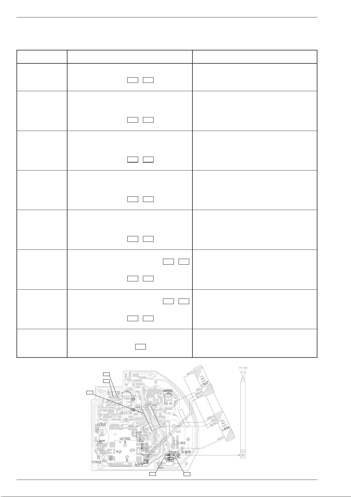
2. Tuner
Meßgeräte: Meßsender, Wobbelsender, Oszilloskop, Frequenzzähler.
Funktionsschalter: Radio
Abgleich Vorbereitung Abgleichvorgang
1. AM-ZF
2. MW Oszillator
3. MW Vorkreis
4. LW Oszillator
5. LW Vorkreis
6. FM Oszillator
7. FM Vorkreis
8. FM-MPX (Stereo)
Mit T501 auf Maximum einstellen.
f
u
(bei 515kHz)
mit L504 auf Maximum einstellen.
f
o
(bei 1630kHz)
mit VTC501(B) auf Maximum einstellen.
Abgleich wechselseitig wiederholen.
Bei 558kHz
mit L506 (MW-Antennenspule) auf Maximum
einstellen (verschieben).
Bei 1440kHz
mit VCT501(A) auf Maximum einstellen.
Abgleich wechselseitig wiederholen.
f
o
(bei 292kHz)
mit TC502 auf Maximum einstellen.
Bei 153kHz
mit L507 (LW-Antennenspule) auf Maximum
einstellen (verschieben).
Bei 261kHz
mit TC501 auf Maximum einstellen.
Abgleich wechselseitig wiederholen.
f
u
(bei 87,35MHz)
mit L503 auf Maximum einstellen.
f
o
(bei 108,25MHz)
mit VCT501(C) auf Maximum
einstellen.
Abgleich wechselseitig wiederholen.
Bei 88MHz mit L502 auf Maximum einstellen (verbiegen).
Bei 106MHz mit VCT501(D) auf Maximum einstellen.
Abgleich wechselseitig wiederholen.
Mit VR501 76kHz ± 100Hz einstellen.
Wobbelsender 465kHz über Rahmenantenne in L506
(Ferritantenne) einkoppeln.
Oszilloskop an Meßpunkt
TP 6
/
TP 7
(IC501 Pin 5/6).
Bandschalter: MW
Drehkoanschlag: MW f
u
515kHz, f
o
1630kHz
Meßsendersignal über Rahmenantenne in L506 (Ferrit-
antenne) einkoppeln (f
mod
= 1kHz, m = 30%, U
a
nur so groß,
daß das Signal gerade erkennbar ist).
Oszilloskop an Meßpunkt
TP 6
/
TP 7
(IC501 Pin 5/6).
Bandschalter: MW
MW 558kHz, MW 1440kHz
Meßsendersignal über Rahmenantenne in L506 (Ferrit-
antenne) (f
mod
= 1kHz, m = 30%, U
a
nur so groß, daß das
Signal gerade erkennbar ist).
Oszilloskop an Meßpunkt
TP 6
/
TP 7
(IC501 Pin 5/6).
Bandschalter: MW
Drehkoanschlag: f
o
292kHz
Meßsendersignal über Rahmenantenne in L507 (Ferrit-
antenne) einkoppeln (f
mod
= 1kHz, m = 30%, U
a
nur so groß,
daß das Signal gerade erkennbar ist).
Oszilloskop an Meßpunkt
TP 6
/
TP 7
(IC501 Pin 5/6).
Bandschalter: LW
LW 153kHz, LW 261kHz
Meßsendersignal über Rahmenantenne in L507 (Ferrit-
antenne) einkoppeln (f
mod
= 1kHz, m = 30%, U
a
nur so groß,
daß das Signal gerade erkennbar ist).
Oszilloskop an Meßpunkt
TP 6
/
TP 7
(IC501 Pin 5/6).
Bandschalter: LW
Drehkoanschlag: FM f
u
87,35MHz, f
o
108,25MHz
Meßsendersignal über 10nF an Meßpunkt
TP 1
/
TP 2
(Masse), (f
mod
= 1kHz, ∆f = 22,5kHz, U
a
nur so groß, daß
das Signal gerade erkennbar ist).
Oszilloskop an Meßpunkt
TP 6
/
TP 7
(IC501 Pin 5/6).
Bandschalter: FM
FM 88MHz, FM 106MHz
Meßsendersignal über 10nF an Meßpunkt
TP 1
/
TP 2
(Masse), (f
mod
= 1kHz, ∆f = 22,5kHz, U
a
nur so groß, daß
das Signal gerade erkennbar ist).
Oszilloskop an Meßpunkt
TP 6
/
TP 7
(IC501 Pin 5/6).
Bandschalter: FM
Meßsendersignal keines
IC501 zwischen Pin 1 und Pin 29 kurzschließen.
Frequenzzähler an Meßpunkt
TP 5
(IC501 Pin 4).
TP 2
TP 1
TP 7
TP 6
TP 5
 Loading...