


 Loading...
GA-C621-SU8
User's Manual
Rev. 1001


Copyright
© 2018 GIGA-BYTE TECHNOLOGY CO., LTD. All rights reserved.
The trademarks mentioned in this manual are legally registered to their respective owners.
Disclaimer
Information in this manual is protected by copyright laws and is the property of GIGABYTE.
Changes to the specifications and features in this manual may be made by GIGABYTE without prior notice.
No part of this manual may be reproduced, copied, translated, transmitted, or published in any form or by any means without GIGABYTE's prior written permission.
For product-related information, check on our website at: https://www.gigabyte.com

Table of Contents
GA-C621-SU8 Motherboard Layout................................................................................. |
5 |
|
Box Contents.................................................................................................................... |
|
6 |
Chapter 1 Hardware Installation...................................................................................... |
7 |
|
1-1 |
Installation Precautions..................................................................................... |
7 |
1-2 |
Product Specifications...................................................................................... |
8 |
1-3 |
Installing the CPU........................................................................................... |
11 |
1-4 |
Installing the Memory...................................................................................... |
12 |
1-5 |
Back Panel Connectors.................................................................................. |
13 |
1-6 |
Internal Connectors........................................................................................ |
15 |
Chapter 2 BIOS Setup................................................................................................... |
26 |
|
2-1 |
Startup Screen................................................................................................ |
26 |
2-2 |
Main................................................................................................................ |
27 |
2-3 |
Advanced........................................................................................................ |
28 |
2-4 |
Platform Configuration.................................................................................... |
31 |
2-5 |
Socket Configuration...................................................................................... |
33 |
2-6 |
Server Mgmt .................................................................................................. |
35 |
2-7 |
Security........................................................................................................... |
36 |
2-8 |
Boot................................................................................................................ |
37 |
2-9 |
Save & Exit..................................................................................................... |
38 |
Chapter 3 Application.................................................................................................... |
39 |
|
Regulatory Statements.............................................................................................. |
48 |
|
Contact Us................................................................................................................. |
49 |
|
- 4 -
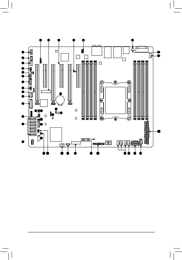
GA-C621-SU8 Motherboard Layout
|
39 |
30 |
37 |
2 |
1 |
36 |
33 |
|
|
|
|
|
21 |
|
|
|
|
|
|
25 |
34 |
|
|
|
|
|
|
25 |
|
|
|
|
|
|
4 |
|
|
|
|
|
|
8 |
|
|
|
|
|
|
5 |
|
|
|
|
|
|
10 |
|
|
|
|
|
|
7 |
|
|
|
|
|
|
9 |
|
|
38 |
|
|
|
|
|
|
|
|
|
|
18 |
|
|
|
|
|
|
16 |
|
|
|
|
|
|
15 |
14 |
|
22 |
|
|
|
|
|
|
|
|
||
|
|
|
3 |
|
|
|
6 |
|
|
23 |
|
|
|
|
|
|
|
|
|
|
|
12 |
|
|
|
|
|
29 |
28 |
|
|
|
|
|
26

 28 32
28 32 


13 11 25 17 31 35 19 25 24 27 20
1 |
BMC_VGA |
11 |
S_SGPIO |
21 |
UID |
31 |
PCIEX2_M2 |
|
|
|
|
|
|
|
|
2 |
BMC_WATCHD |
12 |
SATA_DOM0 |
22 |
CLR_CMOS |
32 |
F_USB30C |
|
|
|
|
|
|
|
|
3 |
Buzzer |
13 |
SATA_DOM1 |
23 |
CI |
33 |
F_AUDIO |
4 |
COMB |
14 |
VRM_SCL |
24 |
CPU_FAN1 |
34 |
THB_C |
5 |
SMB_IPMB |
15 |
VRM_SDA |
25 |
SYS_FAN1~6 |
35 |
F_LED1 |
6 |
I_SGPIO1 |
16 |
FUSB30 |
26 |
ATX |
36 |
F_LED2 |
7 |
I_SGPIO2 |
17 |
VROC |
27 |
ATX8P |
37 |
BMC_LED1 |
8 |
WOL |
18 |
FUSB2 |
28 |
S-SATA0~1 |
38 |
BAT |
9 |
SMB |
19 |
F_PANEL |
29 |
I-SATA0~5 |
39 |
SMB_VMD |
10 |
TPM |
20 |
PMBUS |
30 |
PCIEX4_M2 |
|
|
- 5 -

Box Contents
55 |
GA-C621-SU8 motherboard |
|
|
55 |
Motherboard driver disk |
55 |
Six SATA cables |
55 |
Quick Installation Guide |
55 |
I/O Shield |
- 6 -

Chapter 1 Hardware Installation
1-1 Installation Precautions
The motherboard contains numerous delicate electronic circuits and components which can become damaged as a result of electrostatic discharge (ESD). Prior to installation, carefully read the user's manual and follow these procedures:
•• Prior to installation, make sure the chassis is suitable for the motherboard.
•• Prior to installation, do not remove or break motherboard S/N (Serial Number) sticker or warranty sticker provided by your dealer. These stickers are required for warranty validation.
•• Always remove the AC power by unplugging the power cord from the power outlet before installing or removing the motherboard or other hardware components.
•• When connecting hardware components to the internal connectors on the motherboard, make sure they are connected tightly and securely.
•• When handling the motherboard, avoid touching any metal leads or connectors.
•• It is best to wear an electrostatic discharge (ESD) wrist strap when handling electronic components such as a motherboard, CPU or memory. If you do not have an ESD wrist strap, keep your hands dry and first touch a metal object to eliminate static electricity.
•• Prior to installing the motherboard, please have it on top of an antistatic pad or within an electrostatic shielding container.
•• Before connecting or unplugging the power supply cable from the motherboard, make sure the power supply has been turned off.
•• Before turning on the power, make sure the power supply voltage has been set according to the local voltage standard.
•• Before using the product, please verify that all cables and power connectors of your hardware components are connected.
•• To prevent damage to the motherboard, do not allow screws to come in contact with the motherboard circuit or its components.
•• Make sure there are no leftover screws or metal components placed on the motherboard or within the computer casing.
•• Do not place the computer system on an uneven surface.
•• Do not place the computer system in a high-temperature or wet environment.
•• Turning on the computer power during the installation process can lead to damage to system components as well as physical harm to the user.
•• If you are uncertain about any installation steps or have a problem related to the use of the product, please consult a certified computer technician.
•• If you use an adapter, extension power cable, or power strip, ensure to consult with its installation and/or grounding instructions.
- 7 -
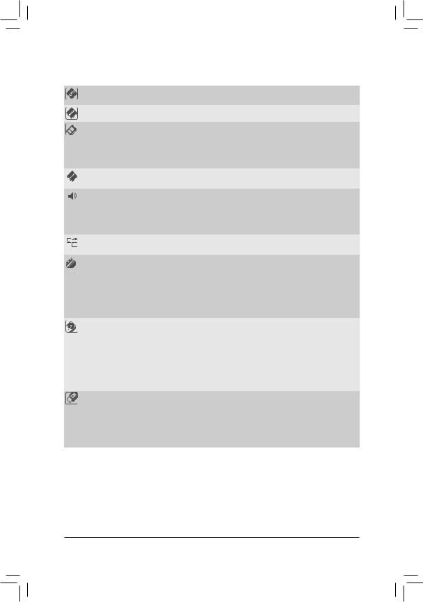
1-2 |
Product Specifications |
||
|
|
|
|
|
CPU |
|
1st and 2nd Generation Intel® Xeon® Scalable Processors, LGA 3647 Socket P |
|
|
|
(Narrow) with 2 UPI support of up to 10.4 GT/s, CPU TDP support up to 165W |
|
Chipset |
|
Intel® C621 Chipset |
|
Memory |
|
8 x DDR4 DIMM sockets supporting up to 1 TB of system memory |
|
|
|
6 channel memory architecture |
|
|
|
Support for DDR4 2666 MHz memory modules if use a Skylake CPU |
|
|
|
Support for DDR4 2933 MHz memory modules if use a Cascade lake CPU |
|
|
|
Support for ECC RDIMM/RDIMM 3DS/LRDIMM/LRDIMM 3DS memory modules |
|
Onboard |
|
ASPEED® AST2500: |
|
Graphics |
|
- 1 x D-Sub port, supporting a maximum resolution of 1920x1200@60 Hz |
|
Audio |
|
Realtek® ALC1220-VB2 codec |
|
|
|
* The back panel line out jack supports DSD audio. |
|
|
|
High Definition Audio |
|
|
|
2/4/5.1/7.1-channel |
|
|
|
Support for S/PDIF Out |
|
LAN |
|
1 x Realtek RTL8211E chip (10/100/1000 Mbit) (LAN1) |
|
|
2 x Intel® 210AT GbE LAN chips (10/100/1000 Mbit) (LAN2, LAN3) |
|
|
|
||
|
Expansion Slots |
|
1 x PCI Express x16 slot, running at x16 (PCIEX16_5) |
|
|
|
* For optimum performance, if only one PCI Express graphics card is to be installed, |
|
|
|
be sure to install it in the PCIEX16 slot. |
|
|
|
2 x PCI Express x16 slots, running at x8 (PCIEX8_1, PCIEX8_3) |
|
|
|
2 x PCI Express x8 slots, running at x8 (PCIEX8_4, PCIEX8_6) |
|
|
|
1 x PCI Express x8 slot, running at x4 (PCIEX4_2) |
|
|
|
(All of the PCI Express slots conform to PCI Express 3.0 standard.) |
|
Storage Interface |
|
Chipset: |
|
|
|
- 1 x M.2 connector (Socket 3, M key, type 2260/2280 SATA and PCIe x2 SSD |
|
|
|
support) (PCIEX2_M2) |
|
|
|
- 1 x M.2 connector (Socket 3, M key, type 2242/2260/2280 PCIe x4/x2 SSD |
|
|
|
support) (PCIEX4_M2) |
|
|
|
- 2 x SATA 6Gb/s connectors (S-SATA0~1) |
|
|
|
- 6 x SATA 6Gb/s connectors (I-SATA0~5) |
|
|
|
- Support for RAID 0, RAID 1, RAID 5, and RAID 10 |
|
USB |
|
Chipset+ ASMedia® USB 3.1 Gen 2 Controller: |
|
|
|
- 2 x USB 3.1 Gen 2 Type-A ports (red) on the back panel |
|
|
|
Chipset: |
|
|
|
- 5 x USB 3.1 Gen 1 ports (2 ports on the back panel, 1 port onboard, 2 ports |
|
|
|
available through the internal USB header) |
|
|
|
- 2 x USB 2.0/1.1 ports available through the internal USB header |
- 8 -
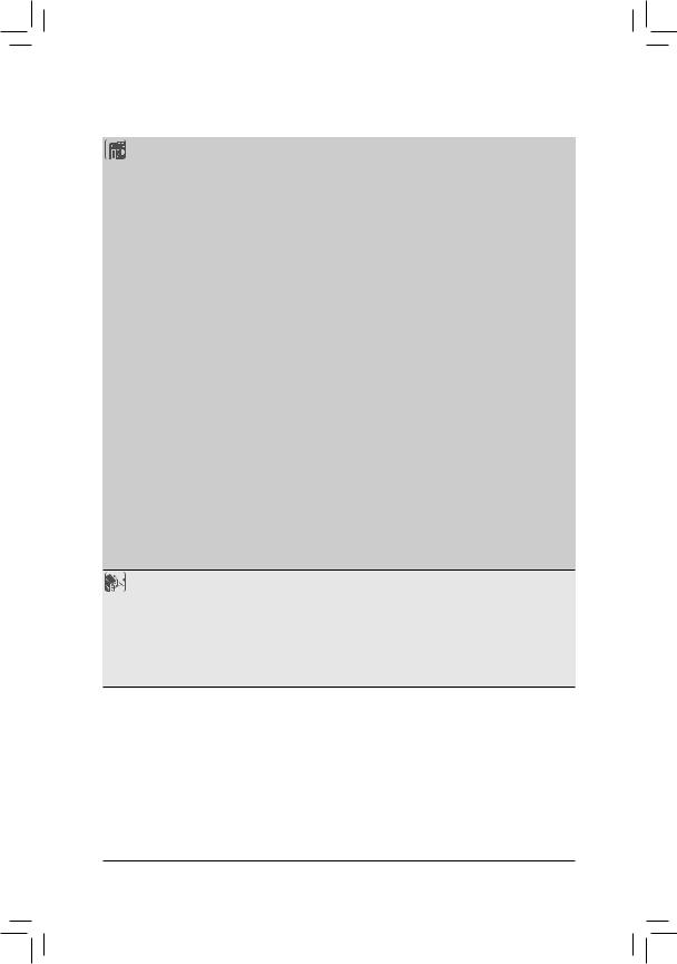
Internal |
|
1 x 24-pin ATX main power connector |
Connectors |
|
1 x 8-pin ATX 12V power connector |
|
1 x CPU fan header |
|
|
6 x system fan headers |
|
|
8 x SATA 6Gb/s connectors |
|
|
2 x SATA DOM power headers |
|
|
2 x M.2 Socket 3 connectors |
|
|
1 x front panel header |
|
|
1 x front panel audio header |
|
|
1 x USB Type-C™ port, with USB 3.1 Gen 1 support |
|
|
1 x USB 3.1 Gen 1 header |
|
|
1 x USB 2.0/1.1 header |
|
|
1 x Thunderbolt™ add-in card connector |
|
|
1 x Trusted Platform Module (TPM) header |
|
|
1 x serial port header |
|
|
1 x chassis intrusion header |
|
|
1 x Clear CMOS jumper |
|
|
3 x SATA SGPIO headers |
|
|
|
1 x BMC_VGA jumper |
|
1 x BMC_WATCHD jumper |
|
|
1 x wake on LAN header |
|
|
1 x IPMB connector |
|
|
1 x SMB jumper |
|
|
1 x VRM SMB Clock jumper |
|
|
1 x VRM SMB Data jumper |
|
|
1 x Intel® VROC Upgrade Key header |
|
|
1 x NVMe SMBus (I2C) header |
|
|
|
1 x buzzer |
|
1 x NVMe SMBUS Control header |
|
 Back Panel
Connectors
1 x D-Sub port
1 x serial port
1 x UID button
2 x USB 3.1 Gen 2 Type-A ports (red)2 x USB 3.1 Gen 1 ports
3 x RJ-45 ports
1 x optical S/PDIF Out connector
5 x audio jacks
- 9 -
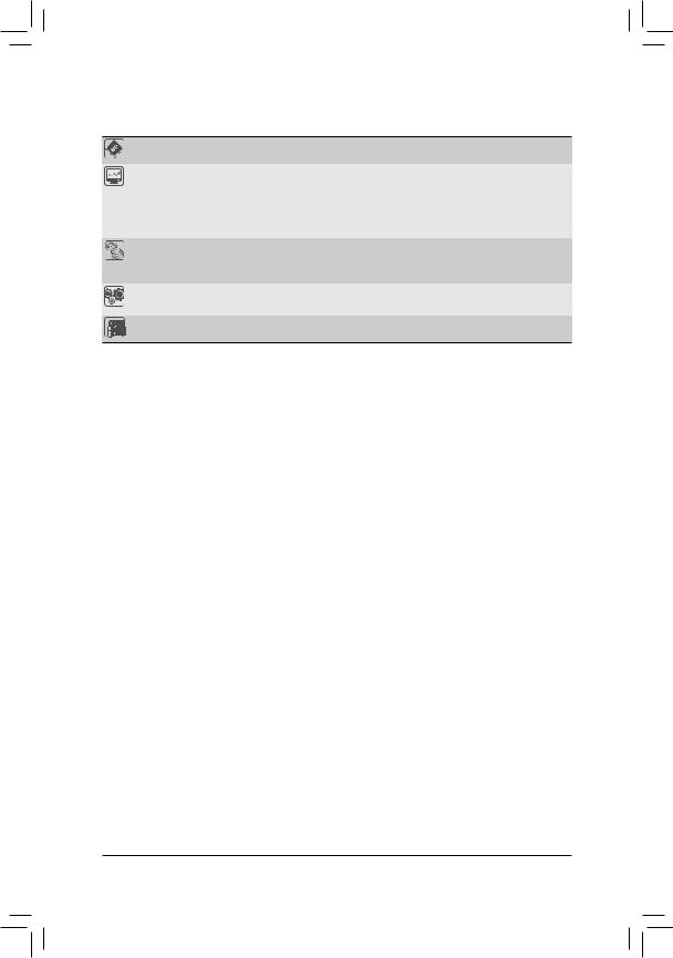
I/O Controller |
|
ASPEED® AST2500 BMC chip |
Hardware |
|
Voltage detection |
Monitor |
|
Temperature detection |
|
Fan speed detection |
|
|
Fan speed control |
|
|
* Whether the fan speed control function is supported will depend on the fan you install. |
|
BIOS |
1 x 256 Mbit flash |
|
|
Use of licensed AMI BIOS |
|
|
PnP 1.0a, DMI 2.7, WfM 2.0, SM BIOS 2.7, ACPI 5.0 |
|
Operating |
Support for Windows 10 64-bit |
|
System |
||
|
||
Form Factor |
ATX Form Factor; 30.5cm x 24.4cm |
*GIGABYTE reserves the right to make any changes to the product specifications and product-related information without prior notice.
- 10 -
1-3 |
Installing the CPU |
|
|
Read the following guidelines before you begin to install the CPU: |
|
|
•• |
Make sure that the motherboard supports the CPU. |
|
•• |
Always turn off the computer and unplug the power cord from the power outlet before installing the |
|
|
CPU to prevent hardware damage. |
|
•• |
Locate the pin one of the CPU. The CPU cannot be inserted if oriented incorrectly. (Or you may |
|
•• |
locate the notches on both sides of the CPU and alignment keys on the CPU socket.) |
|
Apply an even and thin layer of thermal grease on the surface of the CPU. |
|
|
•• |
Do not turn on the computer if the CPU cooler is not installed, otherwise overheating and damage |
|
•• |
of the CPU may occur. |
|
Set the CPU host frequency in accordance with the CPU specifications. It is not recommended |
|
|
|
that the system bus frequency be set beyond hardware specifications since it does not meet the |
|
|
standard requirements for the peripherals. If you wish to set the frequency beyond the standard |
|
|
specifications, please do so according to your hardware specifications including the CPU, graphics |
|
|
card, memory, hard drive, etc. |
Installing the CPU
Locate the alignment keys on the motherboard CPU socket and the notches on the CPU.
C
B
A
1
C
3
2
 B
B
A
|
|
8 |
4 |
6 |
5 |
|
||
|
|
7 |
- 11 -
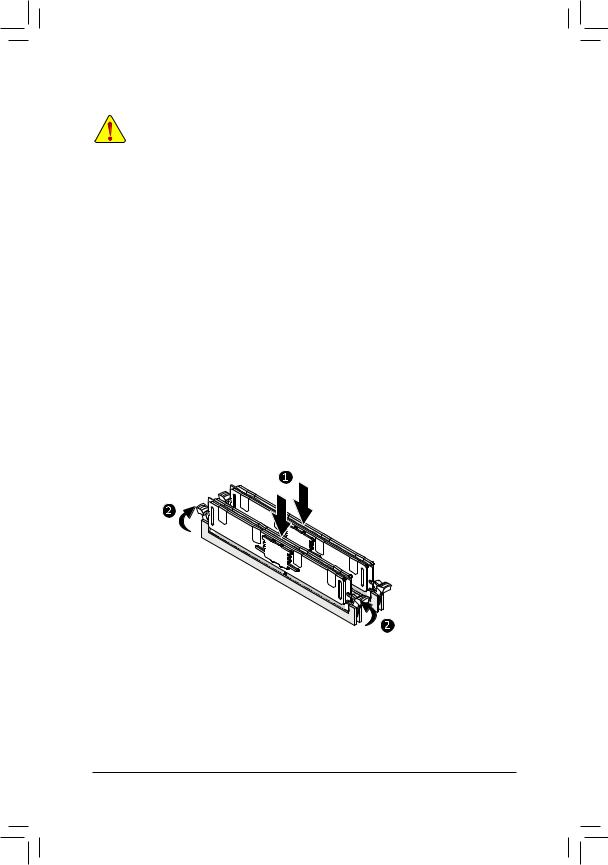
1-4 Installing the Memory
Read the following guidelines before you begin to install the memory:
•• Make sure that the motherboard supports the memory. It is recommended that memory of the same capacity, brand, speed, and chips be used.
(Go to GIGABYTE's website for the latest supported memory speeds and memory modules.)
•• Always turn off the computer and unplug the power cord from the power outlet before installing the memory to prevent hardware damage.
•• Memory modules have a foolproof design. A memory module can be installed in only one direction. If you are unable to insert the memory, switch the direction.
6 Channel Memory Configuration
This motherboard supports 6 Channel Technology. After the memory is installed, the BIOS will automatically detect the specifications and capacity of the memory.
The eight DDR4 memory sockets are divided into 6 channels as following:
Channel 1: DIMM-A1, DIMM-A2Channel 2: DIMM-B1Channel 3: DIMM-C1Channel 4: DIMM-D1, DIMM-D2Channel 5: DIMM-E1Channel 6: DIMM-F1
Due to CPU limitations, read the following guidelines before installing the memory in 6 Channel mode.
1.6 Channel mode cannot be enabled if only one memory module is installed.
2.It is recommended that memory of the same capacity, brand, speed, and chips be used.
Note: When installing the memory in Channel 1 or Channel 4, make sure to begin with DIMM-A1 or DIMM-D1, or the system will not boot properly.
- 12 -
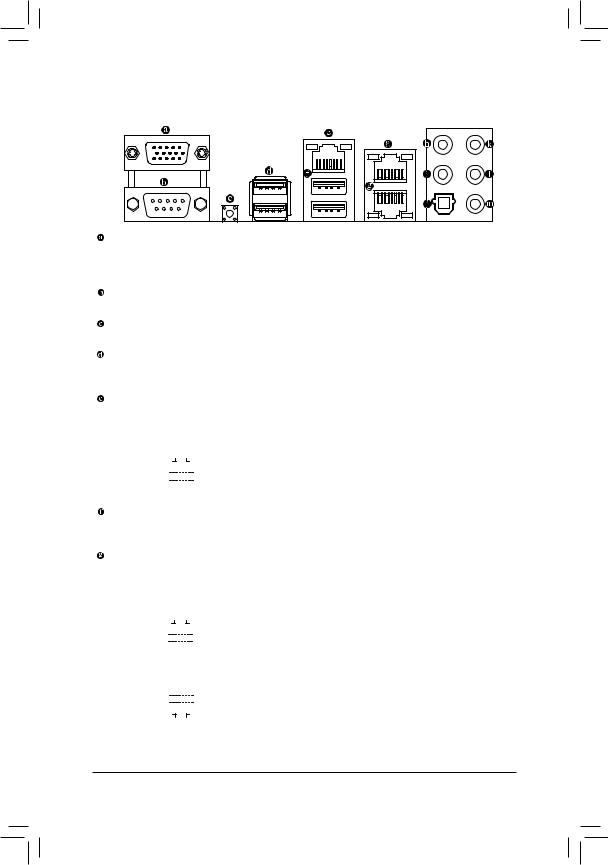
1-5 Back Panel Connectors
D-Sub Port
The D-Sub port supports a 15-pin D-Sub connector and supports a maximum resolution of 1920x1200@60 Hz (the actual resolutions supported depend on the monitor being used). Connect a monitor that supports D-Sub connection to this port.
Serial Port
Use the serial port to connect devices such as a mouse, modem or other peripherals.
UID Button
The UID button.
USB 3.1 Gen 2 Type-A Port (Red)
The USB 3.1 Gen 2 Type-A port supports the USB 3.1 Gen 2 specification and is compatible to the USB 3.1 Gen 1 and USB 2.0 specification. Use this port for USB devices.
IPMI Port (LAN1)
The Gigabit Ethernet LAN port provides Internet connection at up to 1 Gbps data rate. The following describes the states of the LAN port LEDs.
Link LED |
|
|
|
Activity LED |
|
|
|
||||||||||
|
|
|
|
|
|
|
|
|
|
|
|
|
|
|
LED |
State |
Description |
|
|
|
|
|
|
|
|
|
|
|
|
|
|
|
Link (Left) |
Solid Green |
100 Mbps data rate |
|
|
|
|
|
|
|
|
|
|
|
|
|
|
|
Solid Amber |
1 Gbps data rate |
|
|
|
|
|
|
|
|
|
|
|
|
|
|
|
|
|
||
|
|
|
|
LAN Port |
Activity (Right) |
Blinking Yellow |
Active |
||||||||||
|
|
|
|
|
|
|
|||||||||||
USB 3.1 Gen 1 Port
The USB 3.1 Gen 1 port supports the USB 3.1 Gen 1 specification and is compatible to the USB 2.0 specification. You can use this port for USB devices.
GbE LAN Port (LAN2)(LAN3)
The Gigabit Ethernet LAN port provides Internet connection at up to 1 Gbps data rate. The following describes the states of the LAN port LEDs.
Activity LED |
|
|
Link LED |
|
|
|
||||||||
|
|
|
|
|
|
|
|
|
|
|
|
LED |
State |
Description |
|
|
|
|
|
|
|
|
|
|
|
|
Link (Right) |
Solid Green |
100 Mbps data rate |
|
|
|
|
|
|
|
|
|
|
|
|
Solid Amber |
1 Gbps data rate |
|
|
|
|
|
|
|
|
|
|
|
|
|
|
||
|
|
|
|
LAN Port |
Activity (Left) |
Blinking Yellow |
Active |
|||||||
|
|
|
|
|
|
|
||||||||
|
|
|
|
LAN Port |
|
|
|
|||||||
|
|
|
|
|
|
|
|
|
|
|
|
LED |
State |
Description |
|
|
|
|
|
|
|
|
|
|
|
|
Link (Right) |
Solid Green |
100 Mbps data rate |
|
|
|
|
|
|
|
|
|
|
|
|
|||
|
|
|
|
|
|
|
|
|
|
|
|
|
Solid Amber |
1 Gbps data rate |
|
|
|
|
|
|
|
|
|
|
|
|
Activity (Left) |
Blinking Yellow |
Active |
Link LED |
|
|
Activity LED |
|||||||||||
|
|
|
|
|
||||||||||
- 13 -
Center/Subwoofer Speaker Out
Use this audio jack to connect center/subwoofer speakers in a 5.1/7.1-channel audio configuration.
Rear Speaker Out
This jack can be used to connect rear speakers in a 4/5.1/7.1-channel audio configuration.
Optical S/PDIF Out Connector
This connector provides digital audio out to an external audio system that supports digital optical audio. Before using this feature, ensure that your audio system provides an optical digital audio in connector.
Line In
The line in jack. Use this audio jack for line in devices such as an optical drive, walkman, etc.
Line Out
The line out jack. Use this audio jack for a headphone or 2-channel speaker. This jack can be used to connect front speakers in a 4/5.1/7.1-channel audio configuration.
Mic In
The Mic in jack.
•• When removing the cable connected to a back panel connector, first remove the cable from your device and then remove it from the motherboard.
•• When removing the cable, pull it straight out from the connector. Do not rock it side to side to prevent an electrical short inside the cable connector.
- 14 -
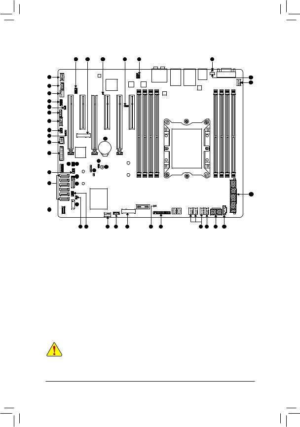
1-6 |
Internal Connectors |
|
|
||||
|
|
397 |
30 |
37 |
2 |
1 |
36 |
33 |
|
|
|
|
|
|
21 |
|
|
|
|
|
|
|
25 |
34 |
|
|
|
|
|
|
|
25 |
|
|
|
|
|
|
|
4 |
|
|
|
|
|
|
|
8 |
|
|
|
|
|
|
|
5 |
|
|
|
|
|
|
|
10 |
|
|
|
|
|
|
|
7 |
|
|
|
|
|
|
|
9 |
|
|
|
38 |
|
|
|
|
|
|
|
|
|
|
|
18 |
|
|
|
|
|
|
|
16 |
|
|
|
|
|
|
|
|
15 |
14 |
|
22 |
|
|
|
|
|
|
|
|
|
||
|
|
|
|
3 |
|
|
|
6 |
|
|
|
23 |
|
|
|
|
|
|
|
|
|
|
|
|
|
12 |
|
|
|
|
|
29 |
|
28 |
|
|
|
|
|
26

 28 32
28 32 


13 11 25 17 31 35 19 25 24 27 20
1 |
BMC_VGA |
11 |
S_SGPIO |
21 |
UID |
31 |
PCIEX2_M2 |
2 |
BMC_WATCHD |
12 |
SATA_DOM0 |
22 |
CLR_CMOS |
32 |
F_USB30C |
3 |
Buzzer |
13 |
SATA_DOM1 |
23 |
CI |
33 |
F_AUDIO |
|
|
|
|
|
|
|
|
4 |
COMB |
14 |
VRM_SCL |
24 |
CPU_FAN1 |
34 |
THB_C |
|
|
|
|
|
|
|
|
5 |
SMB_IPMB |
15 |
VRM_SDA |
25 |
SYS_FAN1~6 |
35 |
F_LED1 |
|
|
|
|
|
|
|
|
6 |
I_SGPIO1 |
16 |
FUSB30 |
26 |
ATX |
36 |
F_LED2 |
|
|
|
|
|
|
|
|
7 |
I_SGPIO2 |
17 |
VROC |
27 |
ATX8P |
37 |
BMC_LED1 |
|
|
|
|
|
|
|
|
8 |
WOL |
18 |
FUSB2 |
28 |
S-SATA0~1 |
38 |
BAT |
9 |
SMB |
19 |
F_PANEL |
29 |
I-SATA0~5 |
39 |
SMB_VMD |
10 |
TPM |
20 |
PMBUS |
30 |
PCIEX4_M2 |
|
|
Read the following guidelines before connecting external devices:
•• First make sure your devices are compliant with the connectors you wish to connect.
•• Before installing the devices, be sure to turn off the devices and your computer. Unplug the power cord from the power outlet to prevent damage to the devices.
•• After installing the device and before turning on the computer, make sure the device cable has been securely attached to the connector on the motherboard.
- 15 -
Loading...