

Page 1

633HC STEAM STERILIZER
USER MANUAL
61301607026 REV B US
Page 2

Page 3

633HC STEAM STERILIZER
USER MANUAL
61301607026 REV B US
Page 4
USER MANUAL
61301607026 REV B US
MARCH 2008
Getinge®, Biosign®, and EZ-VU® are registered trademarks.
Copyright ©2007–2008 Getinge USA, Inc.
PUBLICATION HISTORY
Revision Date Reason
A 8/2007 Initial release
B 3/2008 Changes due to product maturity
For quality service on the 633HC Steam Sterilizer and information on our
Performance Assurance Plan, contact:
Getinge USA, Inc.
1777 East Henrietta Road
Rochester, NY 14623-3133
Phone: 1-800-950-9912
www.getingeusa.com
NOTE
This manual contains proprietary information of Getinge USA, Inc. It shall
not be reproduced in whole or in part without the written permission of
Getinge USA, Inc.
This manual is intended for qualified technicians with specialized training. If
you require additional help, contact the company service representative.
WARNING
POSSIBILITY OF INJURY: Misuse of equipment or bypassing its safety
features may result in personal injury.
CAUTION
POSSIBILITY OF DAMAGE TO EQUIPMENT: Misuse of equipment may
result in equipment damage.
POSSIBILITY OF DAMAGE TO EQUIPMENT: The 633HC Steam Sterilizer is
designed to steam sterilize hospital goods and solutions. This equipment is
NOT intended for use other than expressly stated.
ii USR 61301607026 Rev B US
Page 5

SECTION 1 PREFACE
633HC Steam Sterilizer
TABLE OF CONTENTS
Special Safety Instructions . . . . . . . . . . . . . . . . . . . . . . . . . . . . . . . . . . . . ix
Summary of Contents . . . . . . . . . . . . . . . . . . . . . . . . . . . . . . . . . . . . . . .1–1
Environmental Impact Assessment. . . . . . . . . . . . . . . . . . . . . . . . . . . . .1–2
Manual Conventions . . . . . . . . . . . . . . . . . . . . . . . . . . . . . . . . . . . . . . . .1–3
Symbols Used in This Manual . . . . . . . . . . . . . . . . . . . . . . . . . . . . . . . .1–3
Descriptions of the Symbols on the Equipment . . . . . . . . . . . . . . . . . . .1–4
Switches . . . . . . . . . . . . . . . . . . . . . . . . . . . . . . . . . . . . . . . . . . . . . .1–4
Indicators . . . . . . . . . . . . . . . . . . . . . . . . . . . . . . . . . . . . . . . . . . . . .1–5
Labels . . . . . . . . . . . . . . . . . . . . . . . . . . . . . . . . . . . . . . . . . . . . . . . .1–5
SECTION 2 SAFETY
SECTION 3 INTRODUCTION
General . . . . . . . . . . . . . . . . . . . . . . . . . . . . . . . . . . . . . . . . . . . . . . . . . .2–1
Product Liability . . . . . . . . . . . . . . . . . . . . . . . . . . . . . . . . . . . . . . . . . . .2–3
Isolating Device. . . . . . . . . . . . . . . . . . . . . . . . . . . . . . . . . . . . . . . . . . . .2–3
Safety Features . . . . . . . . . . . . . . . . . . . . . . . . . . . . . . . . . . . . . . . . . . . .2–4
Door Lockout . . . . . . . . . . . . . . . . . . . . . . . . . . . . . . . . . . . . . . . . . .2–4
Door Obstruction Switch . . . . . . . . . . . . . . . . . . . . . . . . . . . . . . . . .2–4
Models . . . . . . . . . . . . . . . . . . . . . . . . . . . . . . . . . . . . . . . . . . . . . . . . . .3–2
Controls and Indicators. . . . . . . . . . . . . . . . . . . . . . . . . . . . . . . . . . . . . .3–3
Control Panel Navigation . . . . . . . . . . . . . . . . . . . . . . . . . . . . . . . . . . . .3–7
Process Screens. . . . . . . . . . . . . . . . . . . . . . . . . . . . . . . . . . . . . . . .3–7
Selecting a Process Screen . . . . . . . . . . . . . . . . . . . . . . . . . . . . . . .3–9
Softkeys . . . . . . . . . . . . . . . . . . . . . . . . . . . . . . . . . . . . . . . . . . . . . . . .3–10
Disabling or Enabling the Controls . . . . . . . . . . . . . . . . . . . . . . . . . . . .3–12
Turning the Controls ON or OFF. . . . . . . . . . . . . . . . . . . . . . . . . . . . . .3–13
Navigation Basics . . . . . . . . . . . . . . . . . . . . . . . . . . . . . . . . . . . . . . . . .3–13
Directional Arrows . . . . . . . . . . . . . . . . . . . . . . . . . . . . . . . . . . . . .3–13
Enter . . . . . . . . . . . . . . . . . . . . . . . . . . . . . . . . . . . . . . . . . . . . . . . .3–14
Selecting an Item from a List . . . . . . . . . . . . . . . . . . . . . . . . . . . . .3–14
USR 61301607026 Rev B US iii
Page 6

Table of Contents
Entering an Alphanumeric Value. . . . . . . . . . . . . . . . . . . . . . . . . . 3–14
Entering Values in Dialog Boxes. . . . . . . . . . . . . . . . . . . . . . . . . . 3–15
Responding to Yes/No Message Boxes. . . . . . . . . . . . . . . . . . . . 3–16
Exiting from a Screen . . . . . . . . . . . . . . . . . . . . . . . . . . . . . . . . . . 3–16
Operating the Printer. . . . . . . . . . . . . . . . . . . . . . . . . . . . . . . . . . . . . . 3–17
Status Indicator. . . . . . . . . . . . . . . . . . . . . . . . . . . . . . . . . . . . . . . 3–18
Advancing the Paper . . . . . . . . . . . . . . . . . . . . . . . . . . . . . . . . . . 3–18
Using the Lever. . . . . . . . . . . . . . . . . . . . . . . . . . . . . . . . . . . . . . . 3–18
Saving Printouts . . . . . . . . . . . . . . . . . . . . . . . . . . . . . . . . . . . . . . 3–19
Tearing Off Printer Paper . . . . . . . . . . . . . . . . . . . . . . . . . . . . . . . 3–19
Replacing the Printer Paper . . . . . . . . . . . . . . . . . . . . . . . . . . . . . 3–19
Storing and Handling Paper Rolls . . . . . . . . . . . . . . . . . . . . . . . . 3–22
Printing a Duplicate Record . . . . . . . . . . . . . . . . . . . . . . . . . . . . . 3–22
Reading the Cycle Printout . . . . . . . . . . . . . . . . . . . . . . . . . . . . . . . . . 3–23
Cycle Start and Parameters . . . . . . . . . . . . . . . . . . . . . . . . . . . . . 3–23
Phases . . . . . . . . . . . . . . . . . . . . . . . . . . . . . . . . . . . . . . . . . . . . . 3–23
Validating the Exposure Phase . . . . . . . . . . . . . . . . . . . . . . . . . . . 3–24
SECTION 4 OPERATION
Sequence of Operation . . . . . . . . . . . . . . . . . . . . . . . . . . . . . . . . . . . . . 4–1
Operating the Sterilizer . . . . . . . . . . . . . . . . . . . . . . . . . . . . . . . . . . . . . 4–2
Start of Day Checklist . . . . . . . . . . . . . . . . . . . . . . . . . . . . . . . . . . . 4–2
Turning the Controls ON . . . . . . . . . . . . . . . . . . . . . . . . . . . . . . . . . 4–2
Operational Readiness . . . . . . . . . . . . . . . . . . . . . . . . . . . . . . . . . . 4–2
Previewing and Selecting a Cycle . . . . . . . . . . . . . . . . . . . . . . . . . 4–3
Operating the Sterilizer Door. . . . . . . . . . . . . . . . . . . . . . . . . . . . . . . . . 4–6
Safety Features . . . . . . . . . . . . . . . . . . . . . . . . . . . . . . . . . . . . . . . . 4–7
Opening and Closing the Sterilizer Door . . . . . . . . . . . . . . . . . . . . 4–7
Load Preparation. . . . . . . . . . . . . . . . . . . . . . . . . . . . . . . . . . . . . . . . . . 4–9
Techniques for Loading . . . . . . . . . . . . . . . . . . . . . . . . . . . . . . . . . . . . 4–11
Flash Sterilization . . . . . . . . . . . . . . . . . . . . . . . . . . . . . . . . . . . . . 4–13
Loading Accessories . . . . . . . . . . . . . . . . . . . . . . . . . . . . . . . . . . . . . . 4–14
Operating the Loading Car and the Transfer Carriage . . . . . . . . . 4–14
Rack and Extendable Shelves . . . . . . . . . . . . . . . . . . . . . . . . . . . 4–20
Loading the Sterilizer. . . . . . . . . . . . . . . . . . . . . . . . . . . . . . . . . . . . . . 4–22
Processing a Cycle . . . . . . . . . . . . . . . . . . . . . . . . . . . . . . . . . . . . . . . 4–23
End of Cycle Routine . . . . . . . . . . . . . . . . . . . . . . . . . . . . . . . . . . . . . 4–25
Unloading the Sterilizer . . . . . . . . . . . . . . . . . . . . . . . . . . . . . . . . . . . . 4–27
iv USR 61301607026 Rev B US
Page 7

633HC Steam Sterilizer
End of Day Checklist . . . . . . . . . . . . . . . . . . . . . . . . . . . . . . . . . . . . . .4–29
Closing the Door. . . . . . . . . . . . . . . . . . . . . . . . . . . . . . . . . . . . . . .4–29
Turning the Controls OFF . . . . . . . . . . . . . . . . . . . . . . . . . . . . . . . .4–29
Blowing Down the Steam Boiler . . . . . . . . . . . . . . . . . . . . . . . . . .4–29
Canceling a Cycle (Manual Abort) . . . . . . . . . . . . . . . . . . . . . . . . . . . .4–30
Advancing a Cycle . . . . . . . . . . . . . . . . . . . . . . . . . . . . . . . . . . . . . . . .4–33
Shutting Down the Sterilizer . . . . . . . . . . . . . . . . . . . . . . . . . . . . . . . . .4–36
Recovering from Electrical Power Failure . . . . . . . . . . . . . . . . . . . . . . .4–38
Power Failure during Standby . . . . . . . . . . . . . . . . . . . . . . . . . . . .4–39
Power Failure during a Cycle . . . . . . . . . . . . . . . . . . . . . . . . . . . . .4–39
Opening the Door Manually . . . . . . . . . . . . . . . . . . . . . . . . . . . . . . . . .4–40
Performance Testing. . . . . . . . . . . . . . . . . . . . . . . . . . . . . . . . . . . . . . .4–53
Biological Monitoring . . . . . . . . . . . . . . . . . . . . . . . . . . . . . . . . . . .4–53
Bowie and Dick Test. . . . . . . . . . . . . . . . . . . . . . . . . . . . . . . . . . . .4–53
Vacuum Leak Test . . . . . . . . . . . . . . . . . . . . . . . . . . . . . . . . . . . . .4–54
SECTION 5 PROCESS DESCRIPTIONS
Factory Set Parameters . . . . . . . . . . . . . . . . . . . . . . . . . . . . . . . . . . . . .5–2
Sterilizer Cycles. . . . . . . . . . . . . . . . . . . . . . . . . . . . . . . . . . . . . . . . . . . .5–3
SECTION 6 TROUBLESHOOTING GUIDE
Display Messages . . . . . . . . . . . . . . . . . . . . . . . . . . . . . . . . . . . . . . . . . .6–1
Diagnostic Message Types. . . . . . . . . . . . . . . . . . . . . . . . . . . . . . . .6–1
Troubleshooting . . . . . . . . . . . . . . . . . . . . . . . . . . . . . . . . . . . . . . . .6–7
Diagnostic Messages . . . . . . . . . . . . . . . . . . . . . . . . . . . . . . . . . . . .6–8
SECTION 7 ROUTINE MAINTENANCE
Maintenance Schedule . . . . . . . . . . . . . . . . . . . . . . . . . . . . . . . . . . . . . .7–1
Daily . . . . . . . . . . . . . . . . . . . . . . . . . . . . . . . . . . . . . . . . . . . . . . . . . . . .7–2
Cleaning the Sediment Screen. . . . . . . . . . . . . . . . . . . . . . . . . . . . .7–2
Cleaning the Bleed Drain Guards. . . . . . . . . . . . . . . . . . . . . . . . . . .7–3
Weekly. . . . . . . . . . . . . . . . . . . . . . . . . . . . . . . . . . . . . . . . . . . . . . . . . . .7–4
Cleaning the Exterior Surfaces. . . . . . . . . . . . . . . . . . . . . . . . . . . . .7–4
Cleaning the Chamber Interior . . . . . . . . . . . . . . . . . . . . . . . . . . . . .7–4
Cleaning the Accessories . . . . . . . . . . . . . . . . . . . . . . . . . . . . . . . . .7–4
Cleaning Materials . . . . . . . . . . . . . . . . . . . . . . . . . . . . . . . . . . . . . .7–4
Cleaning Agents . . . . . . . . . . . . . . . . . . . . . . . . . . . . . . . . . . . . . . . .7–5
USR 61301607026 Rev B US v
Page 8

Table of Contents
Cleaning Methods. . . . . . . . . . . . . . . . . . . . . . . . . . . . . . . . . . . . . . 7–5
Cleaning the Door Gasket(s). . . . . . . . . . . . . . . . . . . . . . . . . . . . . . 7–5
When Required . . . . . . . . . . . . . . . . . . . . . . . . . . . . . . . . . . . . . . . . . . . 7–6
Resetting the Clock and Calendar . . . . . . . . . . . . . . . . . . . . . . . . . 7–6
Installing the Shelves . . . . . . . . . . . . . . . . . . . . . . . . . . . . . . . . . . . 7–8
Removing the Shelves . . . . . . . . . . . . . . . . . . . . . . . . . . . . . . . . . . 7–9
Blowing Down the Steam Boiler (Optional Equipment) . . . . . . . . . 7–9
SECTION 8 OPTIONAL EQUIPMENT
Steam Boiler . . . . . . . . . . . . . . . . . . . . . . . . . . . . . . . . . . . . . . . . . . . . . 8–2
Water Quality Information for Steam Boilers . . . . . . . . . . . . . . . . . 8–3
Blowing Down a Steam Boiler Manually . . . . . . . . . . . . . . . . . . . . 8–4
Steam Boiler Automatic Blow-down Package . . . . . . . . . . . . . . . . . . . 8–8
Setting Up Auto Blow-down. . . . . . . . . . . . . . . . . . . . . . . . . . . . . . 8–9
Steam Boiler Service Maintenance. . . . . . . . . . . . . . . . . . . . . . . . . . . 8–10
Uninterruptible Power Supply . . . . . . . . . . . . . . . . . . . . . . . . . . . . . . . 8–11
General Description . . . . . . . . . . . . . . . . . . . . . . . . . . . . . . . . . . . 8–11
APPENDIX A CONSUMABLE STOCK AND SPARE PARTS
Consumable Stock . . . . . . . . . . . . . . . . . . . . . . . . . . . . . . . . . . . . . . . . A–1
Spare Parts . . . . . . . . . . . . . . . . . . . . . . . . . . . . . . . . . . . . . . . . . . . . . . A–2
APPENDIX B SUPERVISOR FUNCTIONS
Entering a Password . . . . . . . . . . . . . . . . . . . . . . . . . . . . . . . . . . . . . . . B–2
Menu Options . . . . . . . . . . . . . . . . . . . . . . . . . . . . . . . . . . . . . . . . . . . . B–4
Viewing the System Menu Options . . . . . . . . . . . . . . . . . . . . . . . . B–5
Time Settings Menu . . . . . . . . . . . . . . . . . . . . . . . . . . . . . . . . . . . . B–7
Configuration Menu . . . . . . . . . . . . . . . . . . . . . . . . . . . . . . . . . . . . B–8
Password Access . . . . . . . . . . . . . . . . . . . . . . . . . . . . . . . . . . . . . . . . . B–9
Setting Up a User Account. . . . . . . . . . . . . . . . . . . . . . . . . . . . . . B–10
Changing User Access Areas . . . . . . . . . . . . . . . . . . . . . . . . . . . . B–15
Changing a User Password . . . . . . . . . . . . . . . . . . . . . . . . . . . . . B–17
Deleting a User Account. . . . . . . . . . . . . . . . . . . . . . . . . . . . . . . . B–19
Procedures . . . . . . . . . . . . . . . . . . . . . . . . . . . . . . . . . . . . . . . . . . . . . B–20
Editing Cycle Parameters . . . . . . . . . . . . . . . . . . . . . . . . . . . . . . . B–20
Parameter Check . . . . . . . . . . . . . . . . . . . . . . . . . . . . . . . . . . . . . B–30
Setting the Clock and Calendar . . . . . . . . . . . . . . . . . . . . . . . . . . B–32
vi USR 61301607026 Rev B US
Page 9

Setting Up the Auto Blow-down . . . . . . . . . . . . . . . . . . . . . . . . . B–33
Setting Up the Utilities On and Off Times . . . . . . . . . . . . . . . . . . B–35
Bypassing Utility Shutdown Mode . . . . . . . . . . . . . . . . . . . . . . . . B–38
Editing the Cycle Number . . . . . . . . . . . . . . . . . . . . . . . . . . . . . . B–38
Editing the Cycle Name . . . . . . . . . . . . . . . . . . . . . . . . . . . . . . . . B–39
Cycle Assignments . . . . . . . . . . . . . . . . . . . . . . . . . . . . . . . . . . . . . . . B–42
Assigning the Sterilizer Name . . . . . . . . . . . . . . . . . . . . . . . . . . . B–44
Selecting the Language, Date Format, and Units . . . . . . . . . . . . B–46
Setting Up the Display Panel . . . . . . . . . . . . . . . . . . . . . . . . . . . . B–49
Viewing the About Screen . . . . . . . . . . . . . . . . . . . . . . . . . . . . . . B–52
APPENDIX C PARAMETER CHECK FEATURE
Estimating Valid Cycle Parameters. . . . . . . . . . . . . . . . . . . . . . . . . . . . C–1
633HC Steam Sterilizer
APPENDIX D MENU TREE
GLOSSARY
INDEX
USR 61301607026 Rev B US vii
Page 10

Table of Contents
viii USR 61301607026 Rev B US
Page 11

SPECIAL SAFETY INSTRUCTIONS
THE FOLLOWING SAFETY INSTRUCTIONS APPEAR WITHIN THIS
MANUAL ON THE PAGES LISTED AFTER EACH WARNING. READ THEM
CAREFULLY BEFORE OPERATING THE UNIT.
NOTE
“Warning” notes alert the user to the possibility of personal injury.
BURN/PINCH HAZARD: KEEP HANDS AND FINGERS AWAY FROM A
MOVING DOOR. To stop the door direction if your hands or fingers are
accidently caught in the door:
If the door is closing Press one of the following:
633HC Steam Sterilizer
• [OPEN DOOR]
•[CANCEL]
• CONTROLS OFF/ON
If the door is opening Press one of the following:
•[CLOSE DOOR]
•[CANCEL]
• CONTROLS OFF/ON
p. 4–6, p. 4–7
CREUTZFELDT-JAKOB DISEASE (CJD) DECONTAMINATION:
It is the responsibility of the facility to establish internal policies and
procedures relative to processing instruments that have or may have been
exposed to CJD. If instruments exposed to CJD are processed in
accordance with the World Health Organization (WHO) Infection Control
Guidelines for Transmissible Spongiform Encephalopathies (TSE), there
are:
POTENTIAL HAZARDS TO USERS AND REPAIR PERSONNEL:
• Be sure to wear personal protective equipment (PPE) when handling
NaOH liquids.
• Heated NaOH liquids have the potential to injure personnel who handle
the containers.
• Heated NaOH liquids can emit fumes that can be corrosive to eye
tissue and can cause respiratory distress.
• Cleaning residual NaOH from the chamber interior could lead to skin
burns and the production of NaOH aerosol mist.
p. 4–10
USR 61301607026 Rev B US ix
Page 12

Special Safety Instructions
POSSIBILITY OF INJURY: Observe the following loading
recommendations:
• The rack can support a maximum load of 100 lb. An individual shelf can
hold up to 50 lb, evenly distributed. Up to 4 shelves can be placed on
the rack as long as the total maximum weight of 100 lb is not exceeded.
• Do not place more than 20 lb on the end of an extended shelf.
• Liquid loads (hot or cold) should never be placed on an extended shelf.
• Do not extend a shelf with liquid loads (hot or cold).
p. 4–20
BURN HAZARD/SHOCK HAZARD: Before performing any maintenance on
the boiler, allow the boiler to cool down and disconnect the electrical power
at the source. p. 8–10
BURN HAZARD: Before removing a load from the chamber, unseal the door
and wait about a minute for the steam to vent before opening the door.
Stand back to avoid possible burns when lowering the door. p. 4–6, 4–27,
4–40, 4–51
BURN HAZARD: Flash sterilized unwrapped instruments could still be hot
at the end of the cycle. These instruments could burn the patient if used
immediately in surgical procedures. Use personal protective equipment
when removing these items from the sterilizer and allow sufficient time for
them to cool before using them in surgical procedures. p. 4–13, 4–18,
4–20, 4–28, 5–12, 5–15
BURN HAZARD: Hot steam can cause serious injury. DO NOT attempt to
open the sterilizer chamber door unless the CHAMBER pressure gauge on
the front panel reads zero (0 psig) or less (negative). p. 4–40, 4–46
BURN HAZARD: Hot steam can cause serious injury. View the CHAMBER
pressure gauge while the steam bleeds from the chamber. Wait until the
CHAMBER pressure gauge reads zero (0 psig) or less (negative) before
operating manual valves. p. 4–40, 4–42
BURN HAZARD: The door and chamber area could be HOT enough to
cause burns. Wear personal protective equipment (PPE) when loading and
unloading the chamber. p. 4–6, 4–22, 4–27, 4–30, 4–34
BURN HAZARD: The drain valve is hot. Wear protective gloves. p. 8–4,
8–7
BURN HAZARD: To avoid injury, DO NOT turn ON the manual valve labeled
“STEAM TO DOOR(S)” with the chamber door open. p. 4–52
BURN HAZARD: To avoid injury, DO NOT turn the manual valves with the
chamber door open. p. 4–40
x USR 61301607026 Rev B US
Page 13

633HC Steam Sterilizer
FIRE HAZARD: Loose electrical connections may result in an electrical fire.
When performing periodic maintenance, check that the heating elements,
element flange bolts, contactors, and three-phase supply terminal block
are torqued to the values specified in the Technical Manual
(61301607028). p. 8–10
HOT SURFACES: The chamber and sediment drain screens may be hot.
Allow them to cool before attempting to remove them for cleaning. p. 7–3
HOT SURFACES: The chamber and the gasket area could be HOT. Turn
OFF the controls and make sure the sterilizer is cool before cleaning the
gasket or removing the sediment screen for cleaning. p. 4–2
HOT SURFACES: The loading car may be hot enough to cause burns. Wear
protective gloves and eyewear when loading and unloading the
chamber. p. 4–14, 4–18
HOT SURFACES: The loading car or rack and shelves may be hot enough
to cause burns. Wear protective gloves and eyewear when removing the
load from the chamber. p. 4–27
HOT SURFACES: The pipes on the outside of the chamber may be hot!
Avoid touching the pipes when opening and closing the bleed
valves. p. 4–40, 4–42
HOT SURFACES: The rack and shelves may be hot enough to cause burns.
Wear protective gloves when extending the shelves out of the
chamber. p. 7–8, 7–9
HOT SURFACES: The rack and shelves may be hot enough to cause burns.
Wear protective gloves when loading and unloading the chamber. p. 4–20
HOT SURFACE: If the sterilizer is ON, the chamber headring, which houses
the gasket, could be hot. Allow the headring to cool before cleaning the
door gasket. p. 7–5
HOT SURFACE: Make sure the sterilizer chamber is cool before attempting
to clean the interior surfaces. p. 7–4
HOT SURFACE: The chamber and sediment drain screens may be hot.
Allow them to cool before attempting to remove them for cleaning. p. 7–2
POSSIBILITY OF INJURY: After completion of a liquids cycle, remove the
container carefully, taking care not to agitate the liquid. If the load is
agitated when removed from the chamber, the container may burst or
crack. p. 4–27
USR 61301607026 Rev B US xi
Page 14

Special Safety Instructions
POSSIBILITY OF INJURY: Before transporting liquid loads, make sure the
side rails are installed on the loading cart. If the side rails are not installed,
the liquid containers could fall off the loading cart and spill or
break. p. 4–14
POSSIBILITY OF INJURY: Do not operate the door while loading or
unloading the sterilizer. p. 4–6, 4–22, 4–27
POSSIBILITY OF INJURY: If a condition exists OTHER THAN an electrical
outage, call qualified service personnel before operating the sterilizer.
Failure to do so may result in personal injury. p. 4–41, 4–52
POSSIBILITY OF INJURY: If a WATER IN DRAIN message displays, DO
NOT operate the chamber door. Hot water in the chamber may spill if the
door is opened. Wait until the message clears before attempting to open
the door. p. 4–26, 4–41, 4–42, 6–3, 6–13
POSSIBILITY OF INJURY: If the wrong cycle is selected for a liquid load,
the containers may burst or crack during processing. p. 4–23
POSSIBILITY OF INJURY: Manual mode is intended for use by qualified
service personnel to check the function of individual outputs. Attempting to
operate the sterilizer when any output is set for manual operation may
result in possibly dangerous conditions. p. 6–14
POSSIBILITY OF INJURY: Opening the door manually requires retracting
the door gasket, which should be performed by qualified service personnel
only. This procedure requires access to the service side of the
equipment. p. 4–40
POSSIBILITY OF INJURY: Persons entering the chamber could become
trapped. Before entering the chamber, turn the CONTROLS DISABLE/
ENABLE key switch to DISABLE, remove the key, and keep it with you.
When the CONTROLS DISABLE/ENABLE key switch is set to DISABLE, the
control panel is locked and door motion is disabled. p. 3–12, 4–2, 4–6,
4–22, 4–27, 4–30, 4–34, 4–41, 7–2, 7–3, 7–4, 7–5
POSSIBILITY OF INJURY: Retracting the door gasket manually should be
performed by qualified service personnel only. This procedure requires
access to the service side of the equipment. p. 4–42
POSSIBILITY OF INJURY: Steam boiler maintenance should be performed
only by qualified personnel following the procedures in the 600 Series
Technical Manual (61301607028). p. 8–10
POSSIBILITY OF INJURY: The liquids cycle is NOT intended for the
sterilization of liquids intended for direct patient contact. p. 4–9
xii USR 61301607026 Rev B US
Page 15

633HC Steam Sterilizer
POSSIBILITY OF INJURY: The loading car can hold a total maximum load
of 440 lb. The shelves on the car are able to hold a maximum of 275 lb
evenly distributed on each shelf, but the total weight of 440 lb on the car
must not be exceeded. To avoid injury or equipment damage, do not
exceed these weight limits. p. 4–14
POSSIBILITY OF INJURY: Use only vented or open containers to process
liquids in this sterilizer. Use of sealed, unvented containers to process
liquids can result in severe personal injury due to container breakage.
Getinge USA does NOT recommend or endorse use of such
containers. p. 4–7, 4–9, 4–11, 4–22, 4–23, 4–28, 4–30, 4–34, 4–39, 4–41
POSSIBILITY OF INJURY: Wear protective eyewear, clothing, and gloves
when handling liquids in containers. p. 4–22, 4–27
RISK OF INFECTION: Airborne microbial and particulate contamination is
likely to be high in the decontamination area of the sterile processing
department. Wear appropriate personal protective equipment (PPE) when
preparing items for cleaning. p. 4–9, 4–30, 4–34, 4–40
RISK OF INFECTION: The liquids cycle is NOT intended for the sterilization
of liquids intended for direct patient contact. p. 5–16
RISK OF NON-STERILE DEVICE AND POSSIBILITY OF INJURY: Before
pressing START, verify that the appropriate cycle is selected for the load
being processed. p. 4–23
RISK OF NON-STERILE DEVICE: After removing wrapped goods from the
chamber, inspect for residual moisture (wet packs). Moisture on or within a
package can potentially create a pathway for migration of microorganisms
from the outside to the inside of a sterilized package. p. 4–27
RISK OF NON-STERILE DEVICE: If the cycle is aborted, advanced, or
canceled, it must be considered incomplete and the load must be
reprocessed (unwrapped goods or liquids) or repackaged and reprocessed
(wrapped goods). p. 3–4, 4–6, 4–9, 4–23, 4–25, 4–27, 4–30, 4–32, 4–33,
4–35, 4–39, 4–40, 6–1, 6–4, 6–8, 6–13, 6–15
RISK OF NON-STERILE DEVICE: If the PROCESS FAILURE indicator is
flashing, the cycle must be considered incomplete and the load must be
reprocessed (unwrapped goods or liquids) or repackaged and reprocessed
(wrapped goods). p. 4–6, 4–23, 4–25, 4–27, 4–39, 4–40, 6–1, 6–5, 6–6,
6–8
RISK OF NON-STERILE DEVICE: If the sterilizer cancels the cycle due to a
power interruption, the load must be reprocessed (unwrapped goods or
liquids) or repackaged and reprocessed (wrapped goods). p. 4–6, 4–23,
4–25, 4–27, 4–38, 4–40, 6–2, 6–8, 6–12
USR 61301607026 Rev B US xiii
Page 16

Special Safety Instructions
RISK OF NON-STERILE DEVICE: If the wrong cycle is selected, the desired
sterility assurance level (SAL) may not be reached. p. 4–23
RISK OF NON-STERILE DEVICE: The recommended minimum exposure
time and temperature for unwrapped non-porous flash cycle loads (e.g.,
metal instruments) is 3 minutes at 275°F (135°C). p. 4–11, 4–13, 5–12
RISK OF NON-STERILE DEVICE: The sterilizer controls allow users to
modify cycle settings, which may result in cycle parameters that do not
achieve the desired sterility assurance level (SAL). Users with password
access are responsible for validation of any cycles with settings other than
the factory set parameters. p. 5–1, 5–5, 5–9, 5–12, 5–15, 5–18, B–9,
B–21, B–22, B–25, B–28, B–30, C–1
SHOCK HAZARD: Disconnect all electrical supply circuits to ensure that
the sterilizer components will not be energized prior to the performance of
required adjustments and testing. p. 4–42
SHOCK HAZARD: To disconnect all power, turn OFF the sterilizer at the
mains circuit breaker. CONTROLS OFF/ON does not remove primary
power from the sterilizer. p. 2–4
xiv USR 61301607026 Rev B US
Page 17

SECTION 1 PREFACE
Before operating the sterilizer, please read all the instructions and become
familiar with the sterilizer’s design, safety features, and operation.
This manual is intended to provide the knowledge to:
• ensure safe equipment operation with optimal efficiency
• select the appropriate cycle for the load to be sterilized
• handle any nonstandard task, such as assigning passwords
• assist with routine maintenance
This manual is intended for users, supervisors, and qualified maintenance
personnel in the operation of the 633HC Steam Sterilizer. If additional help
is required, contact a qualified Getinge service representative.
The following documentation is supplied with the machine:
• User Manual (61301607026)
• Installation Manual (61301607027)
SUMMARY OF CONTENTS
• Quick Reference Poster (61301607268)
The following documentation is available for purchase:
• Technical Manual (61301607028)
• Parts Catalog (61301607029)
Getinge reserves the right to make changes to specifications and
equipment without prior notice. The information contained within this
manual is current as of the date of issue.
This manual is divided into 13 sections as follows:
• Section 1, “Preface”—includes information regarding the intended
audience and a summary of the contents of the manual
• Section 2, “Safety”—includes all information concerning important
safety issues when using or servicing the sterilizer
• Section 3, “Introduction”—includes information regarding symbols
used within this document and on the equipment as well as basic
navigation concepts
• Section 4, “Operation”—includes information regarding daily checks,
load preparation, and basic operating instructions
USR 61301607026 Rev B US 1–1
Page 18

Preface
• Section 5, “Process Descriptions”—includes factory set parameters
and information regarding cycle parameters and functions
• Section 6, “Troubleshooting Guide”—includes information regarding
error messages and fault analysis
• Section 7, “Routine Maintenance”—includes information regarding
periodic maintenance performed by the user/technician
• Section 8, “Optional Equipment”—includes information regarding
options available for the sterilizer
• Appendix A, “Consumable Stock and Spare Parts”—includes part
numbers of parts and consumables that should be kept on hand
• Appendix B, “Supervisor Functions”—provides information and
instructions for situations that may develop that are not part of
standard sterilizer operation; includes the cycle assignments table
• Appendix C, “Parameter Check Feature”—provides a visual means of
determining whether a specific cycle setting is above the parameter
check limit
• Appendix D, “Menu Tree”—provides a graphic representation of the
user interface
• Glossary—provides written definitions of product or process related
terms used in this manual
ENVIRONMENTAL IMPACT ASSESSMENT
The 633HC Steam Sterilizer contains stainless steel, copper, electronic,
and electrical components, which can be recycled at the end of the unit’s
lifecycle. The sterilizer also contains plastic and batteries that are in the
electronic boards, as well as cadmium in batteries, which can NOT be
recycled and should be disposed of in accordance with local and federal
regulations.
1–2 USR 61301607026 Rev B US
Page 19
MANUAL CONVENTIONS
633HC Steam Sterilizer
Before you begin using this manual, it is important to understand the
conventions used. These conventions are established for visual ease of
use.
[ALL UPPERCASE IN
BRACKETS]
ALL UPPERCASE
WITHOUT BRACKETS
> Leads you through nested menu items and
Italics Alarm and informational messages in the
PARAMETER SETTINGS
ACCESS REQUIRED
Softkeys on the control panel, such as
[CANCEL] or [OK]
Switches and indicators on the control
panel, such as ENTER
dialog box options to a final action, for
example:
Select SYSTEM MENU > enter password >
TIME SETTINGS.
display window, such as the AIR IN SLOW
fault condition
Cross reference to another manual or
guide, for example: See AAMI Standard
ST79.
An alert that a password with appropriate
access rights is necessary to proceed
SYMBOLS USED IN THIS MANUAL
The following symbols with related notes appear in this manual.
“Warning” alerts the user to the possibility
of personal injury.
“Caution” alerts the user to the possibility of
damage to the equipment.
“Note” alerts the user to pertinent facts and
conditions.
USR 61301607026 Rev B US 1–3
Page 20

Preface
!
WS-0091
CONTROLS
OFF ON
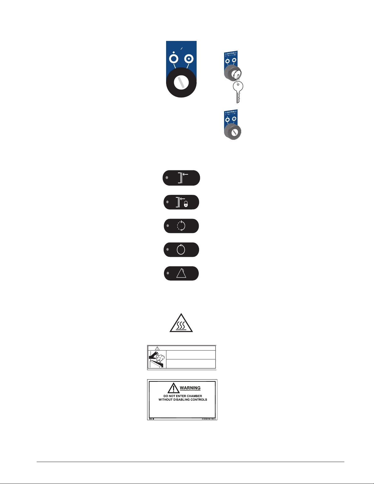
DESCRIPTIONS OF THE SYMBOLS ON THE EQUIPMENT
The following symbols and definitions represent the switches, indicators,
and labels found on the unit.
SWITCHES
OPEN DOOR (also used to unseal the door)
CLOSE DOOR (also used to seal the door
CLEAR ALARM
START
Directional arrows (for navigating display
screens)
ENTER
Softkeys (for selecting softkey options,
such as Save, Cancel, and OK)
CONTROLS OFF/ON
1–4 USR 61301607026 Rev B US
Page 21
633HC Steam Sterilizer
HS
Contact Getinge USA Customer Support (800) 950-9912
If water leaks from the front of the sterilizer,
DO NOT open the door (see User Manual)
Steam released from the sterilizer chamber can
cause serious burns
Stand away while opening the door
WARNING — BURN HAZARD
MGA
61301607429 REV A
INDICATORS
CONTROLS
DISABLE ENABLE
CONTROLS DISABLE/ENABLE
To enable the controls, insert the
key and turn it to ENABLE.
WS-0411-633HC
WS-0243
To disable the controls, turn the
key to DISABLE. Remove the key
to avoid unauthorized operation.
WS-0243-633HC
DOOR(S) CLOSED
DOOR(S) SEALED
IN PROCESS
PROCESS COMPLETE
!
LABELS The following labels on the sterilizer alert personnel to possible hazards.
PROCESSING A TYPE OF LOAD OTHER
THAN DEFINED IN USER
MANUAL COULD BE HAZARDOUS
PROCESS FAILURE
BURN HAZARD: Hot surfaces or heatemitting area. Avoid contact. Risk of burns.
WARNING—BURN HAZARD: Steam
released from the sterilizer chamber can
cause serious burns. Stand away while
opening the door.
WARNING: Do not enter chamber without
disabling controls. Processing a type of
load other than defined in User Manual
could be hazardous.
USR 61301607026 Rev B US 1–5
Page 22
Preface
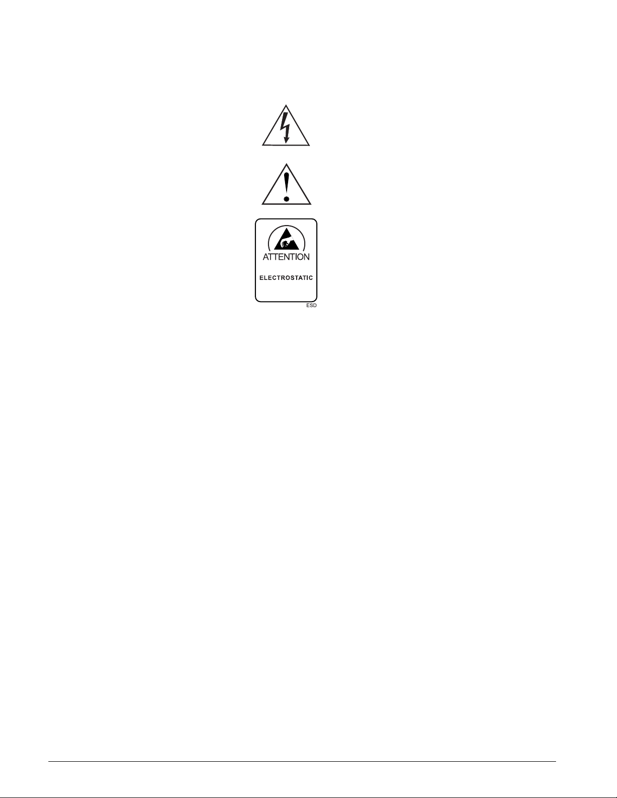
OBSERVE PRECAUTIONS
FOR HANDLING
SENSITIVE
DEVICES
The following labels on the control box and power box alert service
personnel to possible hazards.
HIGH VOLTAGE
CAUTION: To reduce the risk of electrical
shock, do not remove the cover. Refer
servicing to qualified service personnel.
ATTENTION: See the accompanying
documents for further information.
ATTENTION: Observe precautions for
handling electrostatic sensitive devices.
1–6 USR 61301607026 Rev B US
Page 23

GENERAL
SECTION 2 SAFETY
The 633HC Steam Sterilizer is designed to sterilize and dry (where
applicable) typical health care goods. The sterilizer includes pressure pulse
gravity steam, pressure vacuum pulsing, and liquids cycles. This sterilizer
is NOT intended for use other than expressly stated.
This sterilizer is designed with a number of built-in safety devices. To avoid
injury, it is very important that these safety devices are not bypassed or
disabled.
CAUTION
POSSIBILITY OF DAMAGE TO EQUIPMENT: Follow the instructions in this
manual to ensure the safe and efficient performance of the sterilizer. Failure
to comply with these instructions or to provide specific services could void
the warranty.
READ THE MANUAL
• Read all instructions thoroughly before use.
• Before repair or service work is performed, service personnel must
study the manuals and documentation.
AUTHORIZED PERSONNEL ONLY
• Read all instructions thoroughly before operating the sterilizer.
• Service work must be performed by qualified personnel trained on this
equipment.
• The sterilizer must be operated by personnel who know about it and are
trained on its use. Personnel must also receive periodic training on this
equipment.
• Personnel must receive periodic training on the operation and
maintenance of this equipment in accordance with established
procedures for the workplace.
USR 61301607026 Rev B US 2–1
Page 24

Safety
CHEMICAL SAFETY
• Take care when handling any chemical agent used in and around the
sterilizer. Read all details on the container or contact the manufacturer:
– if any agent comes into contact with the operator’s eyes or skin, or
if the vapors are breathed in
– about storing the agent and disposing of empty containers
• Take care when using corrosive detergents, such as Getinge Stainless
Steel Chamber Cleaner or Getinge Schedule 7 Chamber Cleaner.
ELECTRICAL SAFETY
• The front panels and electrical enclosures may be opened only by
authorized and trained personnel. Be sure to switch OFF the electric
power before opening front panels and any electrical enclosures. The
electrical enclosures may contain 24 V, 115 V, 230 V, and three-phase
voltage electrical components.
• Do not touch cables or electrical equipment in the service area.
• The sterilizer must be connected in accordance with the installation
instructions and local safety codes.
• Before welding begins on or close to the sterilizer, all wiring connected
by plugs and sockets must be disconnected from all circuit boards of
the control system.
LOCKOUT
• Always keep the door to the service area locked.
• No personnel should be in the service area while the sterilizer is
running.
• Never bypass the door limit switches of the sterilizer.
• When servicing the unit, CONTROLS DISABLE/ENABLE should be set
to DISABLE. Remove the key and keep it with you.
HOT SURFACES
• There are hot surfaces in the service area. Never touch any piping that
could contain steam.
• The sterilizer uses hot water and steam, which have the potential of
causing burns or serious injuries. Wear personal protective equipment
suitable for hot water and steam.
OTHER CONSIDERATIONS
• Leakage in the system, due to a worn door seal for example, must be
repaired without delay.
• The sterilizer must be kept clean to ensure optimum performance.
• Do not hose down the outside of the sterilizer with water.
2–2 USR 61301607026 Rev B US
Page 25
PRODUCT LIABILITY
ISOLATING DEVICE
633HC Steam Sterilizer
Modifications to the equipment without the express approval of the
manufacturer, or incorrect use of the unit invalidates the manufacturer’s
product liability.
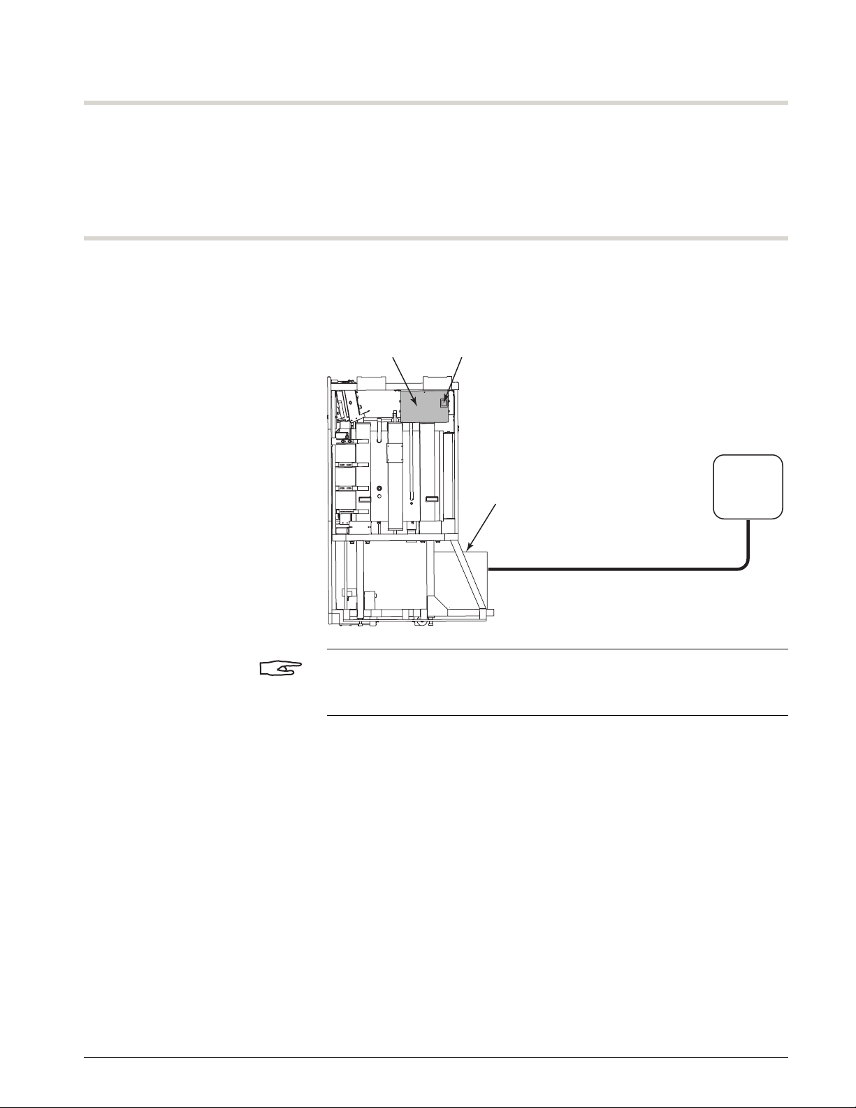
The sterilizer is fitted with a main switch on the power box. The box is
located on the right side of the sterilizer.
FIGURE 2–1. CIRCUIT BREAKER LOCATION
Power Box Main Switch
Steam Boiler
(option)
Heater Voltage
(208/240/480/600 Vac
Three-Phase)
NOTE
Units with boilers are powered by a three-phase circuit that requires a
separate mains disconnect. The boiler has its own circuit breaker.
Mains
Disconnect
Breaker
A07027-K
USR 61301607026 Rev B US 2–3
Page 26
Safety
WS-0421
Top of Door Light Beam
Door Obstruction Switch
SAFETY FEATURES
WARNING
SHOCK HAZARD: To disconnect all power, turn OFF the sterilizer at the
mains circuit breaker. CONTROLS OFF/ON does not remove primary power
from the sterilizer.
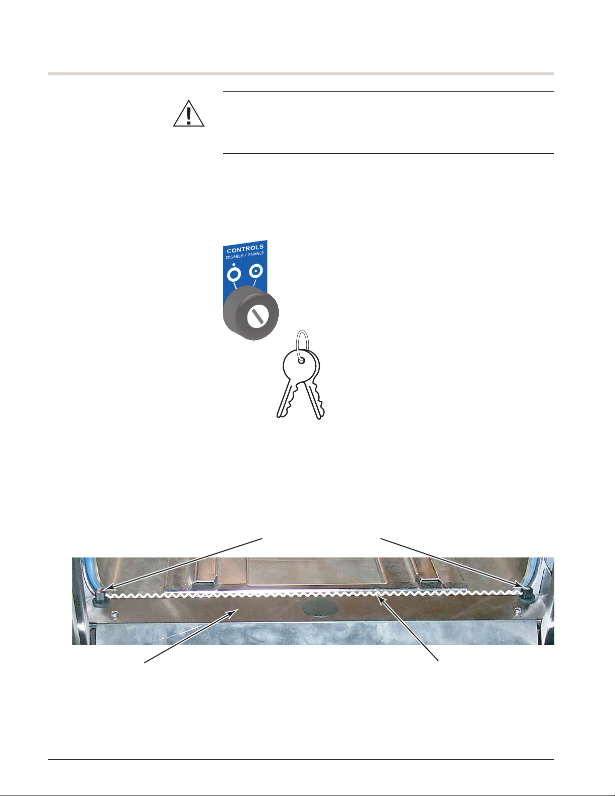
DOOR LOCKOUT The door can be locked in the open position for maintenance inside the
chamber. Turn the key to DISABLE and remove it. To prevent someone from
closing the door during maintenance, keep the keys with you.
FIGURE 2–2. LOCKING THE DOOR IN THE OPEN POSITION
WS-0420
DOOR OBSTRUCTION SWITCH The sterilizer uses a light beam switch at the top of the door to sense when
an object is in the path of the movement of the door. When the light beam
is broken as the door is closing, the door stops then reverses direction for
2seconds.
FIGURE 2–3. DOOR OBSTRUCTION SWITCH
2–4 USR 61301607026 Rev B US
Page 27

SECTION 3 INTRODUCTION
The 633HC Steam Sterilizer is designed to steam-sterilize hospital goods
that are heat and moisture stable. Typical load types include:
• non-porous hard goods, including instruments, basins, cups, tools,
test tubes, and glassware
• wrapped/unwrapped porous goods, including cloth, towels, gowns,
and sheets
• wrapped porous goods, including instruments, basins, and tools
• non-flammable/non-volatile liquids in self-venting or open containers
The liquids cycle is not intended for sterilization of liquids intended for
patient contact.
The following information is covered in this section:
Top ic P ag e
Models 3–2
Controls and Indicators 3–3
Control Panel Navigation 3–7
Softkeys 3–10
Disabling or Enabling the Controls 3–12
Turning the Controls ON or OFF 3–13
Navigation Basics 3–13
Operating the Printer 3–17
Reading the Cycle Printout 3–23
USR 61301607026 Rev B US 3–1
Page 28
Introduction
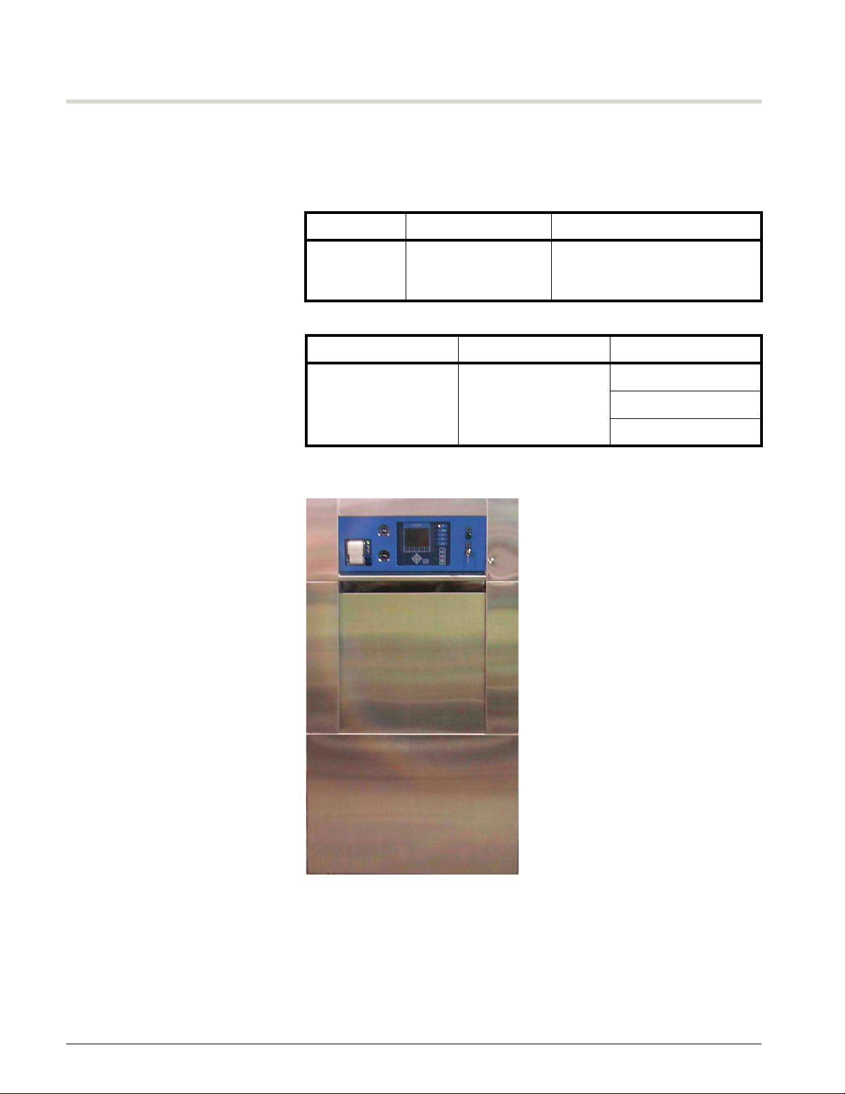
MODELS
The 633HC Steam Sterilizer models and cycle types are listed in Table 3–1
and the vessel dimensions are listed in Table 3–2. See Figure 3–1 for a
picture of the unit.
TABLE 3–1. STEAM STERILIZER MODELS AND CYCLE TYPES
Model Sterilizer Type Cycle Types Available
633HC vacuum/gravity prevacuum, gravity, flash,
liquids, Bowie and Dick test,
and vacuum leak test
TABLE 3–2. VESSEL DIMENSIONS
Height Width Chamber Length
26 in. (672 mm) 26 in. (672 mm) 26 in. (660 mm)
39 in. (1000 mm)
51 in. (1300 mm)
FIGURE 3–1. 633HC STEAM STERILIZER
A07026-A
3–2 USR 61301607026 Rev B US
Page 29
CONTROLS AND INDICATORS
!
CONTROLS
OFF
ON
CONTROLS
DISABLE ENABLE
WS-0241 633HC
1
3 2 4
5
67
8 9
CONTROLS
DISABLE ENABLE
WS-0243
WS-0091
CONTROLS
OFF ON
633HC Steam Sterilizer
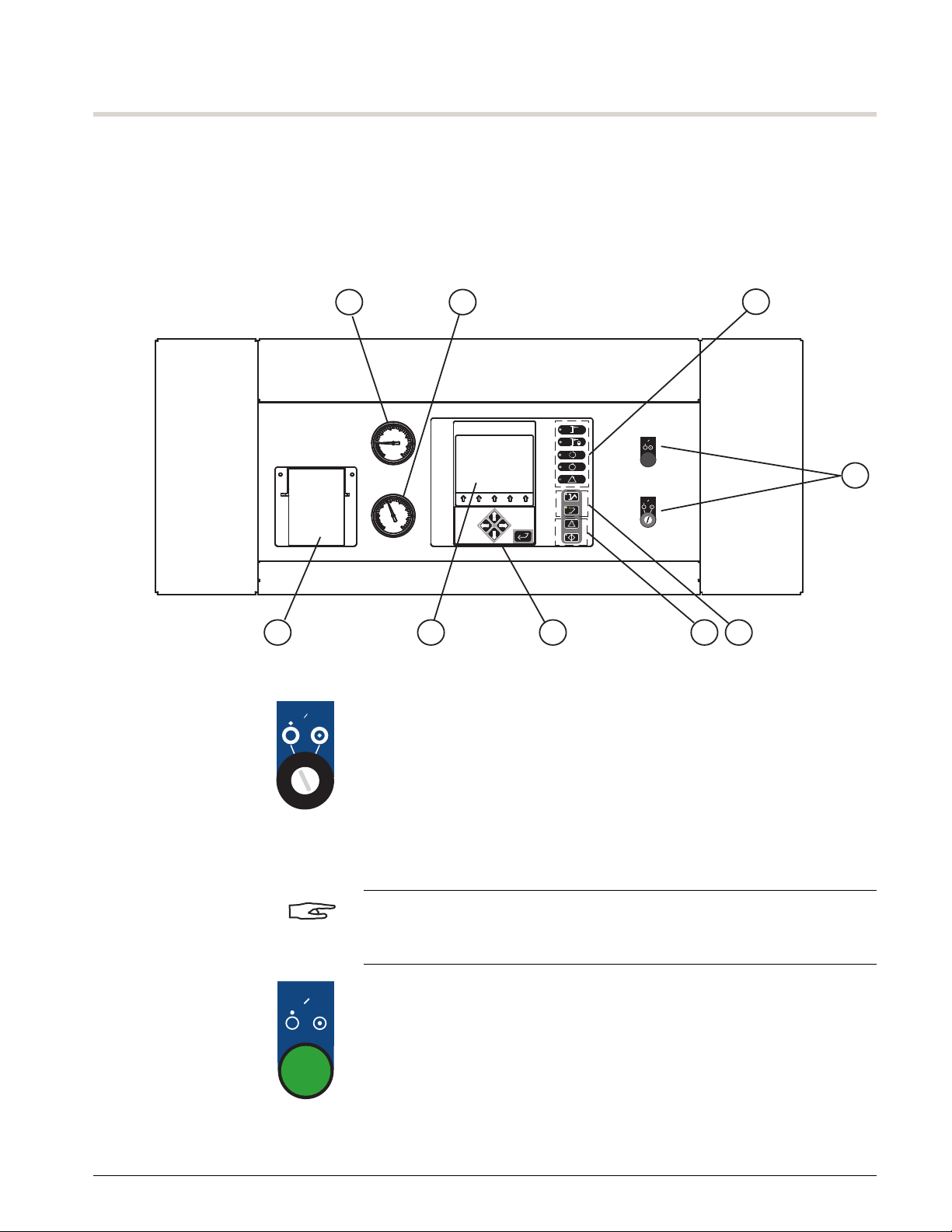
For operational convenience, the sterilizer has an angled primary control
panel on the control end (CE) of the unit. This panel contains a color graphic
display; status indicators; and cycle, door control, and programming
switches. Figure 3–2 is an illustration of the primary control panel.
FIGURE 3–2. STERILIZER CONTROL PANEL
!
1. Controls:
• CONTROLS DISABLE/ENABLE disables the control panel
(preventing door movement during maintenance procedures).
– Sterilizer controls are functional when the key is turned to
ENABLE (key is in the lock).
– Sterilizer controls are not functional when the key is turned to
DISABLE and removed.
NOTE
When servicing the unit, set CONTROLS DISABLE/ENABLE to DISABLE;
remove the key and keep it with you.
• CONTROLS OFF/ON turns the sterilizer controls OFF and ON.
– Sterilizer controls are ON when the push button is pressed in
and illuminated.
– Sterilizer controls are OFF when the push button is released
and the button is not illuminated.
USR 61301607026 Rev B US 3–3
Page 30
Introduction
!
NOTE
If the CONTROLS OFF/ON button is illuminated and the backlight display is
blank (the display is in screen saver mode), press any button (e.g., up arrow
or ENTER) on the control panel to turn ON the display backlight. To adjust
the screen saver delay value, see “Screen Saver” on page B–50.
If the CONTROLS OFF/ON button is pressed during a cycle, the cycle
aborts. This is not the recommended method to abort a cycle manually. To
abort a cycle manually, see “Canceling a Cycle (Manual Abort)” on
page 4–30.
See “End of Cycle Routine” on page 4–25 any time a cycle is aborted.
WARNING
RISK OF NON-STERILE DEVICE: If the cycle is aborted, advanced, or
canceled, it must be considered incomplete and the load must be
reprocessed (unwrapped goods or liquids) or repackaged and reprocessed
(wrapped goods).
2. Cycle switches:
• START begins the selected processing cycle.
• CLEAR ALARM clears display messages and silences any alarm.
See “Display Messages” on page 6–1.
3. Programming switches:
• Directional (up, down, left, and right arrow) switches
– select a cycle; see “Previewing and Selecting a Cycle” on
page 4–3
– enter a password; see “Entering a Password” on page B–2
– change adjustable cycle parameters; see “Editing Cycle
Parameters” on page B–20
– navigate the menus; see “Menu Options” on page B–4
• ENTER enables or stores selections in memory.
• Up arrow softkeys initiate various actions, depending upon the
cycle or cycle phase. The softkey labels appear above the five
arrow softkeys. See “Softkeys” on page 3–10.
4. Door control switches:
•CLOSE DOOR
Press the switch to close the door. Press the switch a second time
to seal the door.
3–4 USR 61301607026 Rev B US
Page 31

633HC Steam Sterilizer
!
a bc
d
e
g
j
WS-0104
•OPEN DOOR
Press the switch to unseal the door. Press the switch a second time
to open the door. See “Operating the Sterilizer Door” on page 4–6.
5. Status indicators:
• DOOR(S) CLOSED indicates the door is closed, but not sealed (or
both doors are closed, but not sealed on a double door unit).
• DOOR(S) SEALED indicates the door is sealed (or both doors are
sealed on a double door unit).
• IN PROCESS indicates a cycle is in progress.
• PROCESS COMPLETE indicates the cycle is complete (green light)
or the cycle is aborted (flashing red light).
• PROCESS FAILURE indicates (flashing red light) that the controls
aborted a cycle automatically due to a process failure, equipment
malfunction, or failure while in standby.
6. The display window is the interface between the user and the sterilizer.
FIGURE 3–3. DISPLAY WINDOW
The display window includes:
a. Exposure Time
b. Exposure Temperature (can display °F or °C); see “Selecting the
Language, Date Format, and Units” on page B–46 to set the
temperature mode
c. Drying Time (not used for liquids cycles)
USR 61301607026 Rev B US 3–5
Page 32

Introduction
d. Cycle information including:
• cycle selected—such as GRAVITY1 and LIQUIDS1
• phase name—such as HEAT-UP, EXPOSURE, DRYING,
EXHAUST, and CYCLE COMPLETE
• time in the cycle—the cycle timer begins when the cycle starts
and continues to increase until the cycle is complete
NOTE
When the phase is STANDBY, the cycle timer does not increase.
• time in current phase—the in-phase timer begins when each
phase starts and resets at the end of each phase
• IN PROCESS—light blue background
• CYCLE COMPLETE—green background
• PROCESS FAILURE—flashing red background
e. Process screen includes:
• a user selectable process screen
– bar graph; see Figure 3–4 on page 3–7
– details; see Figure 3–5 on page 3–8
– plot graph; see Figure 3–6 on page 3–8
• dialog boxes
•password window
NOTE
If all the items in the list do not fit on one screen, a black scroll bar displays
to the right of the list. Use the up and down arrows to view additional items.
f. Critical alarms
• failure conditions
• fault conditions
g. Non-critical information and system messages (informational
messages)
h. through l.—five softkey labels that display different function names
depending on the current screen or cycle phase; see “Softkeys” on
page 3–10
7. The printer provides a record of the cycle. See “Operating the Printer”
on page 3–17.
8. The jacket pressure gauge indicates the current jacket pressure.
9. The chamber pressure gauge indicates the current chamber pressure.
3–6 USR 61301607026 Rev B US
Page 33

633HC Steam Sterilizer
PARA-
METER
SETUP
UNSEAL
SELECT
CYCLE
A07502-C
Time in Cycle
Time in
Current Phase
Estimated Total
Time Remaining
in the Cycle
CONTROL PANEL NAVIGATION
The 633HC Steam Sterilizer has an easy to use interface. This section
covers:
• three process screens; see page 3–7
• softkeys label assignments; see page 3–10
• the backlight display and the sterilizer controls; see page 3–13
• basic navigation of the software; see page 3–13
PROCESS SCREENS The user has the option of selecting one of three process screens:
• a screen with an enlarged timer (bar graph)
• a list of real-time, process-critical values including, but not limited to,
chamber temperature, chamber pressure, jacket temperature,
atmospheric pressure, exposure temperature maximum, exposure
temperature minimum (details)
• a screen with a graphical display (plot graph)
A password is not required to select a process screen.
BAR GRAPH SCREEN
The bar graph screen displays the chamber temperature and pressure as
bar graphs and a digital time representing the time remaining in the cycle.
Each bar graph includes a vertical red line to indicate the following
information:
• On the chamber temperature bar graph, the red line marks the
exposure temperature.
• On the chamber pressure bar graph, the red line marks atmospheric
pressure.
FIGURE 3–4. BAR GRAPH SCREEN
00:30:00
Exposure Time
P10 grv GRAVITY1
01 STA NDBY
Chamber Temp
121.1 C
Exposure Temp
Chamber PSIA
00:30:00
Drying Time
00:00:00
00:24:15
37.3 C
14.68 PSI
0
REMAINING TIME
USR 61301607026 Rev B US 3–7
Page 34

Introduction
DETAILS SCREEN
The details screen displays a list of real-time, process-critical values,
including: chamber temperature, chamber pressure, jacket temperature,
atmospheric pressure, drain temperature, exposure temperature
maximum, exposure temperature minimum, steam table differential, time at
exposure temperature, cycle counter, daily counter, leak test start, leak test
differential, and software version.
NOTE
If all the items in the list do not fit on one screen, a black scroll bar displays
to the right of the list. Use the up and down arrows to view additional items.
FIGURE 3–5. DETAILS SCREEN
00:30:00
Exposure Time
P10 grv GRAVITY1
02 CYCLE COMPLETE
Chamber Temp
Chamb Press/PSIG
Jacket Temp
Atmosphere PSIA
Chamber PSIA
Drain Temp
121.1 C
Exposure Temp
61.2 C
0.00 PSI
122.3 C
14.37 PSI
14.35 PSI
98.6 C
00:30:00
Drying Time
01:36:36
00:04:34
Exp. Temp Max 121.7 C
SETUP
CYCLE
PAR A-
METER
UNSEALSELECT
WS-0012 HC
PLOT GRAPH SCREEN
Using a graphic display, the plot graph screen displays the chamber
temperature and pressure as trend curves.
FIGURE 3–6. PLOT GRAPH SCREEN
00:30:00
Exposure Time
P10 grv GRAVITY 1
02 CYCLE COMPLETE
Chamber Temp
Chamber PSIA
121.1 C
Exposure Temp
81.2
14.35
00:30:00
Drying Time
01:36:36
00:03:42
C
PSI
TIME
01:40
SELECT
CYCLE
PAR A-
METER
UNSEALSETUP
WS-0013 HC
3–8 USR 61301607026 Rev B US
Page 35

633HC Steam Sterilizer
121.1 C
Exposure Temp
00:30:00
Drying Time
P10 grv GRAVITY1
01 STA NDBY
00:30:00
Exposure Time
00:00:00
00:24:15
0
REMAINING TIME
Chamber Temp
14.68 PSI
Chamber PSIA
37.3 C
WS-0014 HC
PARA-
METER
SETUP
UNSEAL
SELECT
CYCLE
121.1 C
Exposure Temp
00:30:00
Drying Time
P10 grv GRAVITY1
01 STA NDBY
00:30:00
Exposure Time
00:00:00
00:24:15
0
REMAINING TIME
Chamber Temp
14.68 PSI
Chamber PSIA
37.3 C
SETUP
DETAILS
PLOT GRAPH
BAR GRAPH
SYSTEM MENU
ABOUT
WS-0445 HC
SELECT
CYCLE
PAR A-
METER
UNSEAL
SELECTING A PROCESS SCREEN
The process screen displays when you turn ON the sterilizer control panel.
See “Turning the Controls ON or OFF” on page 3–13.
FIGURE 3–7. PROCESS (BAR GRAPH) SCREEN
1. Press [SETUP].
The setup menu displays.
FIGURE 3–8. SETUP MENU SCREEN
2. Use the up and down arrows to select the process screen:
•DETAILS
• PLOT GRAPH
USR 61301607026 Rev B US 3–9
• BAR GRAPH
3. Press ENTER.
The selected process screen displays.
Page 36

Introduction
SOFTKEYS
Navigation of the software interface is controlled using the softkeys ( )
that appear at the bottom of each screen. The softkey labels, located
directly above the softkeys, change depending on the current screen or the
cycle phase. The following table shows the labels assigned to each softkey.
NOTE
Access levels assigned determine the screens that are viewed.
3–10 USR 61301607026 Rev B US
Page 37

633HC Steam Sterilizer
TABLE 3–3. SOFTKEY ASSIGNMENTS
Softkey Labels Screen or Procedure
SETUP SELECT
CYCLE
SETUP PARA-
SETUP PARA-
ABORT ADVANCE EXIT Default screen in-cycle (timed phase)
SETUP PARA-
CANCEL Setup menu
CANCEL OK SELECT CYCLE screen
CANCEL MORE
CANCEL HOME OK EDIT PARAMETERS screen [MORE
PARA-
METER
METER
METER
METER
PARAM S
UNSEAL Startup or Default screen
UNSEAL Default screen CYCLE COMPLETE
MORE Default screen in-cycle
(after MORE is pressed)
ABORT Default screen in-cycle (untimed phase)
OK
or
SAVE
Quick Edit Parameters screen
PARAMS]
CANCEL +/- Edit Parameters dialog box
CANCEL EDIT OK VIEW PARAMETERS screen
CANCEL CAPS
LOCK
CANCEL DELETE OK ENTER PASSWORD screen
CANCEL HOME OK
YES NO Confirmation message box (if
CANCEL HOME System Menu options
CANCEL HOME BRIGHT
DEC
DELETE OK ADD USER, ACCESS AREAS or
MACHINE NAME screen
ALARM CLOCK, LANGUAGE DATE
UNITS, or PANEL SETUP screens
preference is enabled)
See “Setting Up the Display Panel” on
page B–49.
BRIGHT
INC
or
SAVE
OK ABOUT screen
Softkeys
USR 61301607026 Rev B US 3–11
Page 38

Introduction
WS-0243-633HC
WS-0411-633HC
DISABLING OR ENABLING THE CONTROLS
The key lockout feature should be used during maintenance and any time
a person needs to enter the sterilizer chamber.
WARNING
POSSIBILITY OF INJURY: Persons entering the chamber could become
trapped. Before entering the chamber, turn the CONTROLS DISABLE/
ENABLE key switch to DISABLE, remove the key, and keep it with you.
When the CONTROLS DISABLE/ENABLE key switch is set to DISABLE, the
control panel is locked and door motion is disabled.
To lockout (disable) the controls:
1. Turn the key located in the CONTROLS DISABLE/ENABLE switch to
DISABLE.
If the CONTROLS OFF/ON button is depressed:
• The CONTROLS OFF/ON button darkens.
• The backlight display turns OFF.
• The controls turn OFF.
Otherwise, the controls and the backlight display remain OFF.
2. Remove the key and keep it with you.
To enable the controls:
1. Insert the key into the CONTROLS DISABLE/ENABLE switch.
2. Turn the key to ENABLE.
If the CONTROLS OFF/ON button is depressed:
• The CONTROLS OFF/ON button switch illuminates and remains
depressed.
• The backlight display illuminates.
• The controls turn ON.
Otherwise, the controls and the backlight display remain OFF.
NOTE
The key cannot be removed from the CONTROLS DISABLE/ENABLE
switch unless set to DISABLE.
3–12 USR 61301607026 Rev B US
Page 39

TURNING THE CONTROLS ON OR OFF
WS-0091
CONTROLS
OFF ON
To turn the backlight display and the controls ON:
1. Check that the controls are enabled. If not, enable them; see “Disabling
or Enabling the Controls” on page 3–12.
2. Press the CONTROLS OFF/ON button.
• The switch illuminates and remains depressed.
• The backlight display illuminates.
• The controls turn ON.
NOTE
If the power is interrupted by pressing CONTROLS ON/OFF accidentally,
turn the controls back ON. The cycle is not canceled if the controls are
turned ON within 2 seconds.
633HC Steam Sterilizer
If primary power is interrupted (e.g., a circuit breaker trips), the cycle is not
canceled if power is restored within 59 seconds.
To turn the backlight display and the controls OFF:
1. Press the CONTROLS OFF/ON button.
NAVIGATION BASICS
DIRECTIONAL ARROWS Each of the directional arrows has a specific function:
•up arrow ( ↑ )
– scrolls up a list on the current screen or window
– when the cursor is activated (blinking cursor), increases the digit or
value that is highlighted
•right arrow (→)
– moves the cursor on the current screen or window right to highlight
a field
•down arrow ( ↓ )
– scrolls down a list on the current screen or window
– when the cursor is activated (blinking cursor), decreases the digit
or value that is highlighted
•left arrow (←)
– moves the cursor on the current screen or window left to highlight
a field
USR 61301607026 Rev B US 3–13
Page 40

Introduction
121.1 C
Exposure Temp
00:30:00
Drying Time
P10 grv GRAVITY1
01 STANDBY
00:30:00
Exposure Time
00:00:00
00:24:15
123456789 0
ABCDEFG HI J
KLMNOPQ R S T
UVWXYZ
!"#%&()\,;
.:
+
SPACE
ÅÄÖÜ
-/ =
ENTER PASSWORD
PASSWORD:
CANCEL
OK
DELETE
WS-0017 HC
ENTER Use the ENTER switch to:
• accept numbers and letters when entering passwords, machine
names, or changing a parameter setting
• select an item from a list (such as a cycle from the list of available
cycles, a menu option, or a parameter)
• store a cycle selection in memory
SELECTING AN ITEM FROM A LIST
ENTERING AN ALPHANUMERIC VALUE
Selecting an item from a list is very simple. Use the up and down arrows to
select the item and press ENTER to store the selection in memory.
For more detailed instructions, see “Previewing and Selecting a Cycle” on
page 4–3.
When an alphanumeric value needs to be entered, a screen similar to
Figure 3–9 on page 3–14 displays.
FIGURE 3–9. KEYBOARD SCREEN
3–14 USR 61301607026 Rev B US
When the keyboard screen displays, the blinking cursor is positioned at the
location of the first character of the string and the first key on the keyboard
is highlighted. Use the directional arrows to navigate to the appropriate
character; press ENTER to select the character. The selected character or
# sign displays in the position of the blinking cursor and the blinking cursor
moves to the right of the character. After entering the last character of the
string, press [OK].
NOTE
The right/left directional arrows wrap, that is, pressing the right arrow when
the last key in a row is highlighted selects the first key in the same row; and
vice versa. The up/down directional arrows behave in a corresponding
manner. You can use this feature to reduce the number of switch presses
needed to enter the alphanumerica value.
Page 41

633HC Steam Sterilizer
121.1 C
Exposure Temp
00:30:00
Drying Time
P10 grv GRAVITY1
01 STANDBY
00:30:00
Exposure Time
00:00:00
00:24:15
0
REMAINING TIME
Chamber Temp
14.68 PSI
Chamber PSIA
37.3 C
00:30:00
CANCEL
WS -0211 HC
Te
mp
PS
Chamber PSIA
3
C
Exposure Time
(00:01:00 - 06:00:00)
00:30:00 hh:mm:ss
Softkeys:
• [CANCEL] returns to the previous screen without accepting the
alphanumeric value.
• [DELETE] deletes the character to the left of the cursor.
• [OK] accepts the alphanumeric value and, in the case of the password,
displays the next screen if a valid password is entered.
For more detailed instructions, see:
• “Entering a Password” on page B–2
• “Setting Up a User Account” on page B–10
• “Changing a User Password” on page B–17
• “Editing the Cycle Number” on page B–38
• “Editing the Cycle Name” on page B–39
• “Assigning the Sterilizer Name” on page B–44
ENTERING VALUES IN DIALOG BOXES
You change the values of cycle parameters by entering the new values in
dialog boxes. When a dialog box displays over a process screen, the cursor
is flashing, ready for you to enter the new value:
• Use the left and right arrows to select the field you want to change.
• Use the up and down arrows to enter the new value.
• Press ENTER to accept the changes, close the dialog box, and return
the screen to save mode.
FIGURE 3–10. DIALOG BOX FOR VALUE ENTRY
7
68
After the dialog box closes, press [SAVE] to record the new value into
memory and return the screen to read mode. For more detailed
instructions, see “Editing Cycle Parameters” on page B–20.
USR 61301607026 Rev B US 3–15
Page 42

Introduction
NOTE
The dialog box displays the range of allowable values within parentheses. If
you enter a value that is outside this range and press ENTER, the dialog box
does not close but remains open for you to enter a value that is within the
range.
RESPONDING TO YES/NO MESSAGE BOXES
EXITING FROM A SCREEN There are three commands used to exit from a screen:
Yes/No message boxes appear over process screens and are used to
confirm changes made by the user (e.g., Confirm Save/Cancel). The user
responds to the message box by pressing either the [YES] or [NO] softkey
at the bottom of the process screen.
For more detailed instructions, see “Setting Up the Display Panel” on
page B–49.
• [CANCEL] returns to the previous screen without saving changes.
• [HOME] returns to the Process screen and logs out the current user.
• [OK] returns to the previous screen.
In the case of the ENTER PASSWORD screen, pressing [OK] displays
the screen that corresponds to the function selected (when a valid
password is entered).
NOTE
If both [OK] and [CANCEL] softkeys display:
1. Press [OK] to return to the previous screen.
2. When in edit mode (cursor blinking), press [CANCEL] to return to the
previous screen without saving any changes.
When not in edit mode, press [CANCEL] to return to the previous
screen.
If both [OK] and [CANCEL] (or [SAVE] and [CANCEL]) softkeys display, the
CONFIRM CANCEL? YES OR NO prompt displays when [CANCEL] is
pressed.
The CONFIRM CANCEL? prompt can be turned off by changing the
CONFIRM SAVE/CANCEL setting on the PANEL SETUP screen. See
“Setting Up the Display Panel” on page B–49.
3–16 USR 61301607026 Rev B US
Page 43

OPERATING THE PRINTER
633HC Steam Sterilizer
At the beginning of the cycle, the printer records the date and time the cycle
was started, sterilizer name and ID number, cycle count, and cycle
parameter settings.
During the cycle, the printer records the chamber temperature and
chamber pressure at each transition point (start of a new phase), as well as
the time of the transition. During exposure, the temperature and pressure
are printed twice per minute. The program time is reset at the start of each
cycle.
NOTE
The slow print interval (the time between data recordings) is factory set at
1 minute. The fast print interval (the time between recordings during
exposure) is factory set at 30 seconds. The print intervals can be shortened
(to record more data) or lengthened (to conserve paper) by qualified service
personnel.
The temperature and pressure units (°C or °F; psi, kPa, or bar) can be
configured by a user with Configuration password access. See “Selecting
the Language, Date Format, and Units” in the Appendix “Supervisor
Functions.”
The column layout of the printout can be configured by qualified service
personnel.
The printer also records any diagnostic messages that occur during the
cycle, and the time they occurred.
NOTE
Occasionally with the initial introduction of AC power to the sterilizer, the
message “LOW POWER BROWN OUT” may occur on the printout. This
message is normal under power up conditions and no further action is
required.
When removing the load from the sterilizer at the end of the cycle, be sure
the printer’s plastic cover is closed. This prevents residual steam from
condensing on the printout or inside the cover.
If the printer’s plastic cover is open and residual steam condenses on the
printout, it causes darkening of the thermosensitive paper.
The printer has a paper take-up core which holds a complete roll of paper.
If printouts of separate loads are required, this core can be removed. The
printout remains behind the paper cover until the user opens the cover and
tears off the printout.
USR 61301607026 Rev B US 3–17
Page 44

Introduction
STATUS
STATUS
COPY
FEED
SHAFT
TAB
NOTCH
SLOT
CORE
ROLL
COVER
LEVER
CLEAR
COVER
RETAINER
00-01A
COVER SLOT
A00866BC
OFF = NO POWER
ON = READY
BLINKING = PRINTER NOT READY,
PAPER NOT PROPERLY INSERTED,
OR ROLL COVER OPEN
FIGURE 3–11. PRINTER
STATUS INDICATOR The STATUS indicator on the printer blinks when the printer is out of paper
or there is a paper jam.
FIGURE 3–12. STATUS INDICATOR
ADVANCING THE PAPER To advance the paper through the printer, press and hold FEED.
To stop the paper advance, release FEED.
To take up slack paper without advancing more paper:
1. Press and release FEED. Then immediately press and hold FEED.
The core takes up slack paper.
2. Release FEED.
USING THE LEVER
3–18 USR 61301607026 Rev B US
The lever helps remove the core. See Figure 3–11. To remove a full core,
press the lever in the direction of the arrow. This opens the retainer.
Page 45

SAVING PRINTOUTS There are three ways to save printouts:
STATUS
00-01f
STATUS
00-01H
STATU S
00-01G
• full roll—to collect a complete roll on the core
Insert the paper into the slot on the core, and remove the core when it
is full. See “Replacing the Printer Paper” on page 3–19.
• small sections—to collect printouts of shorter periods, such as daily
use
When loading paper, do not insert a new core. Instead, feed the paper
to the area by the shaft. When information is printed, open the clear
cover and tear off the printout.
• separate printouts—to collect individual printouts for each cycle
For separate small printouts, feed the paper out through the cover slot.
During use, keep the clear cover closed. Before opening the sterilizer
door, tear off the printout after each cycle.
633HC Steam Sterilizer
TEARING OFF PRINTER PAPER To tear off the printout for individual cycle records:
1. Press FEED for approximately one second.
This advances the paper beyond the SIGNATURE line of the printout.
2. Open the printer cover.
3. Tear off the printout against the tear blade at the top of the printer.
4. Close the printer cover.
REPLACING THE PRINTER PAPER
To replace the printer paper roll (Figure 3–13 on page 3–20):
1. Remove the used take-up core. See “Removing the Used Take-up
Core” on page 3–21.
2. Insert a new take-up core. See “Inserting a New Take-up Core” on
page 3–21.
3. Insert a new roll. See “Inserting a New Roll” on page 3–21.
4. Load the paper. See “Loading the Paper” on page 3–21.
For small section or separate printouts, see “Saving Printouts” on
page 3–19.
For information on ordering printer paper and cores, see Appendix A,
“Consumable Stock and Spare Parts”.
USR 61301607026 Rev B US 3–19
Page 46

Introduction
00-01-D
STATUS
REMOVE THE USED TAKE-UP CORE
STATUS
ALIGN NOTCHES
WITH TABS
INSERT A NEW TAKE-UP CORE
STATUS
INSERT A NEW ROLL
• PRESS AND RELEASE
• THEN PRESS AND HOLD
FOR 1 REVOLUTION
STATUS
LOAD THE PAPER
FIGURE 3–13. REPLACING THE ROLL
3–20 USR 61301607026 Rev B US
Page 47

633HC Steam Sterilizer
REMOVING THE USED TAKE-UP CORE
The printer has a take-up core which holds a complete roll of paper. The
printout remains behind the clear cover until the cover is opened and the
printout is torn off or the paper roll removed.
1. Open the clear cover.
2. Press and hold the lever in the direction of the arrow.
3. Remove the used core.
NOTE
If printouts of separate loads are required, the take-up core can be
removed.
INSERTING A NEW TAKE-UP CORE
1. Still holding the lever, align the notches on the new core with the tabs
on the shaft. See Figure 3–13 on page 3–20.
2. Release the lever. Seat the new core against the retainer.
INSERTING A NEW ROLL
1. Open the roll cover.
2. Remove the old roll.
3. Insert the new roll as shown.
4. Pull out about 6 inches of paper.
Be sure the plain side of the paper faces you.
LOADING THE PAPER
1. Close the roll cover.
2. Fold the paper as shown in Figure 3–14 on page 3–22.
USR 61301607026 Rev B US 3–21
Page 48

Introduction
00-01B
FOLD
FOLD
FIGURE 3–14. FOLD THE PAPER
3. Rotate the new core so the slot faces you.
4. Insert the paper into the slot.
5. Press and release FEED. Then immediately press and hold FEED.
STORING AND HANDLING PAPER ROLLS
PRINTING A DUPLICATE RECORD
• The core turns.
• Take up the paper at least one full revolution.
6. Release FEED. Close the clear cover.
NOTE
The printer uses a special heat-sensitive paper. The printer does not print
on rolls of plain paper.
The paper should not be exposed to temperatures above 104°F (40°C) for
extended periods of time. Exposure to direct sunlight for several weeks or
longer may darken the paper, making the printout difficult to read.
Direct contact with steam discolors the paper, making the printout difficult
to read. Always close the clear protective cover after replacing the paper
roll or removing printouts from the take-up compartment.
To print a duplicate of the previous cycle record:
1. When the sterilizer is not running a cycle, press and release COPY.
The duplicate record prints.
3–22 USR 61301607026 Rev B US
Page 49

NOTE
COPY functions only from the end of a cycle until the start of the next cycle.
Pressing CYCLE START clears the printer memory.
During a cycle, COPY is disabled.
READING THE CYCLE PRINTOUT
A sample cycle printout of a vacuum cycle run on a 633HC Steam Sterilizer
is shown in Figure 3–15 on page 3–26. The proper interpretation of the
information produced during a cycle is the subject of this section.
NOTE
When a printout of a cycle is produced, the cycle start is near the bottom of
the printout and the end of the cycle is near the top. When reading the
printout, always read from bottom to top.
633HC Steam Sterilizer
CYCLE START AND PARAMETERS
The sample printout shown in Figure 3–15 is from a vacuum cycle. Different
sterilization cycles produce printouts with slightly different information, but
time stamps and pressure and temperature readings are all read in the
same way.
There are 2 printer rates (fast log and slow log). The factory set parameters
are:
• Fast Log prints every 30 seconds during the exposure phase.
• Slow Log prints every 60 seconds during phases other than exposure.
Slow and Fast Log intervals may be adjusted by qualified service personnel.
All times are elapsed time (the amount of time that has elapsed since the
start of the cycle) except for PROCESS START and PROCESS END.
Callout 1 shows a line of text that indicates that a new cycle has started
(DATE:).
The information between Callout 1 and Callout 3 lists some of the
parameters for the cycle. As an example, Callout 2 shows the EXPOSURE
TIME for the current cycle (00:03:00). The EXPOSURE TIME is the amount
of time the EXPOSURE TEMP is maintained.
Callout 3 shows the name of the current cycle. In this example, the cycle is
a vacuum cycle named P1 vac PREVAC1.
PHASES Each time a phase within a cycle starts, the phase name is recorded on the
printout. In the sample printout, Callout 4 shows the beginning of the
EXPOSURE phase.
USR 61301607026 Rev B US 3–23
Page 50

Introduction
Immediately above the word EXPOSURE, the printout displays the time
stamp for the start of the phase, along with the chamber pressure and
temperature. In this example, the printout shows the EXPOSURE phase
started at 00:07:46 into the cycle, and, at that time, the chamber pressure
was 45.86 psia and the chamber temperature was 135.5°C.
During timed phases, the printer reports the appropriate cycle information
including chamber pressure, and chamber temperature readings at regular
intervals. EXPOSURE uses the fast log rate, factory set at 30 seconds.
Therefore, after the start of EXPOSURE at 00:07:46, there are readings at
00:08:17, 00:08:47, and so forth. The sample printout is truncated to fit on
the page; a complete printout displays the pressure and temperature
readings every 30 seconds for the entire 3 minute phase.
When the cycle changes from one phase to the next, the new phase name
is printed along with the time stamp at which the phase begins, as well as
the chamber pressure and temperature readings. In this example, Callout 5
shows the EXHAUST phase starting at 00:10:47 into the cycle. The
beginning of the new phase (EXHAUST) also marks the end of the previous
phase (EXPOSURE).
VALIDATING THE EXPOSURE PHASE
NOTE
Phases do NOT overlap.
Different cycles feature different phases and parameters.
Unlike the EXPOSURE phase where readings are printed at the fast log
rate, the EXHAUST phase readings are reported at the slow log rate.
The following paragraphs use the cycle parameters and results to validate
the EXPOSURE phase.
The start time stamp of each phase within a cycle is printed. Therefore, it is
possible to determine the total time of any given phase. In Figure 3–15,
Callout 4 shows the EXPOSURE phase starting at 00:07:46 into the cycle
and Callout 5 shows the EXHAUST phase starting at 00:10:47 into the
cycle. The total exposure time is the difference between the two start times,
or 00:03:01. This is validated by the EXPOSURE TIME parameter in
Callout 2, which reads 00:03:00.
Examining the EXPOSURE TEMP parameter appearing above Callout 2
reveals the P1 vac PREVAC1 cycle requires an exposure temperature of
135.0°C. During the EXPOSURE phase the temperatures recorded are
between 135.4°C and 135.5°C, which are within acceptable sterilization
variances.
This information shows the EXPOSURE phase is valid because 135.0°C
was achieved and maintained for a time of at least 00:03:00.
3–24 USR 61301607026 Rev B US
Page 51

633HC Steam Sterilizer
CYCLE END
Callout 7 shows a line that reads CYCLE COMPLETE followed by a line
with a time stamp, chamber pressure, and chamber temperature readings.
This is the end of the P1 vac PREVAC1 cycle.
CYCLE RESULTS
Pertinent information regarding the cycle is displayed together for ease of
use. The information includes:
• the number of cycles completed; this counter resets everyday at
midnight (DAILY COUNTER)
• the amount of time the sterilizer was at the exposure temperature (TIME
AT EXP TEMP)
• the minimum (EXP TEMP MIN) and maximum (EXP TEMP MAX)
exposure temperature that occurred during the cycle
USR 61301607026 Rev B US 3–25
Page 52

Introduction
WS-0053-633HC
1. DATE (the date the cycle starts)
Read the tape from bottom to top.
2. Set Exposure time
3. Cycle name
4. The time that has elapsed
from the start of the cycle
to the beginning of the Exposure
phase (the exposure start time)
5. The time that has elapsed
from the start of the cycle
to the beginning of the Exhaust
phase (the exhaust start time)
7. The time that has elapsed
from the start of the cycle
to the end of the cycle
DRYING phase
runs/prints for 16 min
EXPOSURE phase
runs/prints for 3 min.
PROCESS START
(the time of day
the cycle starts)
Top of Printout/End of Cycle
Bottom of Printout/Start of Cycle
PROCESS END
(the time of day
the cycle ends)
6. Total exposure time
00:10:47 (exhaust start time)
- 00:07:46 (exposure start time)
00:03:01 Tot al exposure time
00:27:59 12.58 101.0
CE UNSEALING
00:27:47 4.50 99.5
AIR-IN
00:26:47 0.61 100.9
00:25:47 0.61 101.0
00:24:47 0.60 102.1
01:06:43 4.26 71.9
00:11:40 4.61 76.0
DRYING
00:10:47 45.87 135.5
EXHAUST
00:10:47 45.88 135.5
00:10:17 45.90 135.5
00:08:47 45.85 135.5
00:08:17 45.83 135.4
00:07:47 45.82 135.5
00:07.46 45.86 135.5
EXPOSURE
00:07:00 44.28 134.3
00:06:00 38.92 129.7
00:05:00 5.66 72.8
00:04:57 4.55 73.5
HEAT-UP
NEG TRANS. PT.
00:02:20 9.58 90.2
00:02:00 19.79 114.0
POS. TRANS. PT.
00:01:47 32.27 122.7
00:01:31 23.81 119.2
CONDITIONING
00:01:00 24.79 116.1
00:00:00 14.37 88.5
PURGE
00:00:00 14.36 88.5
STAR T
PROGTIME AI05 AI00
PROGRAM: P1 vac PREVAC1
AI00 Chamber Temp
AI05 Chamber Pressure
SIGNALS
Exposure Temp 135.0 C
BlowDown Durat 00:00:10
Drying Time 00:16:00
Dry 1-=vac 2=grav2 2
Exposure Time 00:03:00
PARAMETERS
CYCLE COUNTER : 355
MACHINE NAME : 633 HC
PROCESS START : 10:46:01
DATE : 09/29/2006
SIGNATURE:................
PROCESS END
11:1 5:0 6
CYCLE RESULTS
Exp. Temp Max 135.5C
Exp. Temp Min 135.3C
Time at Exp Temp 00:03:13
DAILY COUNTER 1
00:28:34 14.33 101.4
CYCLE COMPLETE
FIGURE 3–15. SAMPLE PRINTOUT OF A STERILIZER CYCLE
3–26 USR 61301607026 Rev B US
Page 53

SEQUENCE OF OPERATION
SECTION 4 OPERATION
This section covers the sequence a user may follow when sterilizing a load:
Procedure Page
Start of Day Checklist 4–2
Turning the Controls ON 4–2
Previewing and Selecting a Cycle 4–3
Opening and Closing the Sterilizer Door 4–7
Load Preparation 4–9
Techniques for Loading 4–11
Loading Accessories 4–14
Loading the Sterilizer 4–22
Processing a Cycle 4–23
End of Cycle Routine 4–25
Unloading the Sterilizer 4–27
End of Day Checklist 4–29
This section also covers routine procedures including:
Canceling a Cycle (Manual Abort) 4–30
Advancing a Cycle 4–33
Shutting Down the Sterilizer 4–36
Recovering from Electrical Power Failure 4–38
Opening the Door Manually 4–40
Performance Testing 4–53
USR 61301607026 Rev B US 4–1
Page 54

Operation
OPERATING THE STERILIZER
START OF DAY CHECKLIST
WARNING
HOT SURFACES: The chamber and the gasket area could be HOT. Turn
OFF the controls and make sure the sterilizer is cool before cleaning the
gasket or removing the sediment screen for cleaning.
POSSIBILITY OF INJURY: Persons entering the chamber could become
trapped. Before entering the chamber, turn the CONTROLS DISABLE/
ENABLE key switch to DISABLE, remove the key, and keep it with you.
When the CONTROLS DISABLE/ENABLE key switch is set to DISABLE, the
control panel is locked and door motion is disabled.
Before operating the sterilizer each day:
1. Check the printer paper roll and replace it if necessary. See “Replacing
the Printer Paper” on page 3–19.
2. Inspect and clean the sediment screen in the chamber drain. See
“Cleaning the Sediment Screen” on page 7–2.
TURNING THE CONTROLS ON For information regarding the controls, see “Turning the Controls ON or
OPERATIONAL READINESS
3. Clean the bleed drain guards. See “Cleaning the Bleed Drain Guards”
on page 7–3.
OFF” on page 3–13.
NOTE
If the sterilizer is equipped with a steam boiler, allow the boiler to warm up
for 20 to 30 minutes before running a cycle.
To ensure that the sterilizer is ready for processing without requiring a
warm-up period:
• Leave the sterilizer ON during regular periods of sterilizer inactivity.
• Close but do not seal the sterilizer door(s).
Conduct an air removal performance test (Bowie and Dick Test) if the daily
schedule includes a prevacuum wrapped goods cycle. See “Bowie and
Dick Test” on page 4–53.
4–2 USR 61301607026 Rev B US
Page 55

633HC Steam Sterilizer
121.1 C
Exposure Temp
00:30:00
Drying Time
P10 grv GRAVITY1
01 STA NDBY
00:30:00
Exposure Time
00:00:00
00:24:15
0
REMAINING TIME
Chamber Temp
14.68 PSI
Chamber PSIA
37.3 C
WS-0014 HC
PARA-
METER
SETUP
UNSEAL
SELECT
CYCLE
PREVIEWING AND SELECTING A CYCLE
When making a cycle selection, pressing ENTER displays the exposure
time, exposure temperature, drying time, and the name of the selected
cycle at the top of the SELECT CYCLE screen. See Figure 4–2 on
page 4–4. This feature permits the preview of several different cycle
settings before final selection.
After previewing the cycle, press [OK] to select the cycle.
NOTE
The information that appears in the Process screen depends on the type
currently selected (Details, Plot Graph, or Bar Graph).
Press [CANCEL] at any time to return to the Process screen without
selecting a cycle.
FIGURE 4–1. PROCESS SCREEN (BAR GRAPH)
To select a cycle:
1. From the Process screen, press [SELECT CYCLE].
The SELECT CYCLE screen appears.
USR 61301607026 Rev B US 4–3
Page 56

Operation
SELECT CYCLE
P01
P02
P03
P04
P05
P06
P07
vac PREVAC1
vac PREVAC1
vac PREVAC1
vac PREVAC1
vac PREVAC1
vac PREVAC1
vac PREVAC2
WS-0156 HC
CANCEL
OK
Press ENTER to view
the parameters for the
highlighted cycle.
Use the up/down
arrows to highlight
a cycle.
Press [CANCEL] at any time
to return to the Process screen
without selecting a cycle.
Press [OK]
to conrm the
selected cycle.
FIGURE 4–2. SELECT CYCLE SCREEN
00:30:00
Exposure Time
P10 grv GRAVITY1
01 STA NDBY
SELECT CYCLE
Chamber Temp
P01
vac PREVAC1
P02
vac PREVAC1
37.3 C
P03
vac PREVAC1
P04
vac PREVAC1
P05
vac PREVAC1
P06
vac PREVAC1
P07
vac PREVAC2
CANCEL
121.1 C
Exposure Temp
0
REMAINING TIME
Chamber PSIA
00:30:00
Drying Time
14.68 PSI
00:00:00
00:24:15
OK
WS-0446 HC
2. Use the up and down arrows to scroll the list of cycles.
The black scroll bar at the right side of the screen indicates more cycles
exist than can fit on one screen. Continued scrolling refreshes the
screen and displays any additional cycles.
Stop scrolling when the desired cycle is highlighted.
4–4 USR 61301607026 Rev B US
3. Press ENTER to preview the cycle parameters.
The cycle name and cycle parameters appear at the top of the display.
FIGURE 4–3. SELECTING A CYCLE
00:03:00
Exposure Time
P1 vac PREVAC1
01 STA NDBY
Chamber Temp
37.3 C
135.0 C
Exposure Temp
Chamber PSIA
00:16:00
Drying Time
14.68 PSI
00:00:00
00:24:15
0
REMAINING TIME
Page 57

633HC Steam Sterilizer
4. Verify the cycle parameters are correct for the load.
• If correct, press [OK] to confirm the cycle.
• If not correct, repeat step 2 and step 3 until the correct cycle is
selected.
NOTE
Press [CANCEL] at any time to return to the Process screen without
selecting a cycle.
The Process screen displays.
NOTE
If a cycle is highlighted without pressing ENTER, pressing [OK] confirms the
last cycle entered instead of the cycle currently highlighted.
USR 61301607026 Rev B US 4–5
Page 58

Operation
OPERATING THE STERILIZER DOOR
WARNING
RISK OF NON-STERILE DEVICE: If the cycle is aborted, advanced, or
canceled, it must be considered incomplete and the load must be
reprocessed (unwrapped goods or liquids) or repackaged and reprocessed
(wrapped goods).
RISK OF NON-STERILE DEVICE: If the PROCESS FAILURE indicator is
flashing, the cycle must be considered incomplete and the load must be
reprocessed (unwrapped goods or liquids) or repackaged and reprocessed
(wrapped goods).
RISK OF NON-STERILE DEVICE: If the sterilizer cancels the cycle due to a
power interruption, the load must be reprocessed (unwrapped goods or
liquids) or repackaged and reprocessed (wrapped goods).
BURN/PINCH HAZARD: KEEP HANDS AND FINGERS AWAY FROM A
MOVING DOOR. To stop the door direction if your hands or fingers are
caught in the door accidently:
If the door is closing Press one of the following:
• [OPEN DOOR]
•[CANCEL]
• CONTROLS OFF/ON
If the door is opening Press one of the following:
•[CLOSE DOOR]
•[CANCEL]
• CONTROLS OFF/ON
BURN HAZARD: The door and chamber area could be HOT enough to
cause burns. Wear personal protective equipment (PPE) when loading and
unloading the chamber.
BURN HAZARD: Before removing a load from the chamber, unseal the door
and wait about a minute for the steam to vent before opening the door.
Stand back to avoid possible burns when lowering the door.
POSSIBILITY OF INJURY: Do not operate the door while loading or
unloading the sterilizer.
POSSIBILITY OF INJURY: Persons entering the chamber could become
trapped. Before entering the chamber, turn the CONTROLS DISABLE/
ENABLE key switch to DISABLE, remove the key, and keep it with you.
When the CONTROLS DISABLE/ENABLE key switch is set to DISABLE, the
control panel is locked and door motion is disabled.
4–6 USR 61301607026 Rev B US
Page 59

633HC Steam Sterilizer
WARNING
POSSIBILITY OF INJURY: Use only vented or open containers to process
liquids in this sterilizer. Use of sealed, unvented containers to process
liquids can result in severe personal injury due to container breakage.
Getinge USA does NOT recommend or endorse use of such containers.
CAUTION
POSSIBILITY OF DAMAGE TO EQUIPMENT: Use of sealed, unvented
containers to process liquids can result in permanent damage to the
sterilizer.
SAFETY FEATURES These safety features apply to all units under normal conditions:
• The user cannot close the chamber door when CONTROLS DISABLE/
ENABLE is set to DISABLE.
• The user cannot unseal a door while a cycle is processing.
• If a door is not fully closed, the user cannot seal it.
• If a door does not seal, the cycle does not start.
OPENING AND CLOSING THE STERILIZER DOOR
• If there is pressure or vacuum in the chamber at the end of the cycle,
the user cannot unseal the door.
A motor raises and lowers the door, but does not seal the door. The door is
sealed when START is pressed.
NOTE
The door can also be sealed by pressing CLOSE DOOR again when the
door is already closed.
WARNING
BURN/PINCH HAZARD: KEEP HANDS AND FINGERS AWAY FROM A
MOVING DOOR. To stop the door direction if your hands or fingers are
caught in the door accidently:
If the door is closing Press one of the following:
• [OPEN DOOR]
•[CANCEL]
• CONTROLS OFF/ON
If the door is opening Press one of the following:
•[CLOSE DOOR]
•[CANCEL]
• CONTROLS OFF/ON
USR 61301607026 Rev B US 4–7
Page 60

Operation
NOTE
Wait for approximately 1 minute for the steam to vent before opening the
door.
To open the door:
1. Press OPEN DOOR once.
Stand away from the door area while the door is in motion.
To close the door:
1. Press CLOSE DOOR once.
Stand away from the door area while the door is in motion.
When the door is closed and START is pressed, the door seals
automatically and the selected cycle begins. When a cycle is complete,
the door unseals automatically, but remains closed until OPEN DOOR
is pressed.
4–8 USR 61301607026 Rev B US
Page 61

LOAD PREPARATION
633HC Steam Sterilizer
WARNING
RISK OF INFECTION: Airborne microbial and particulate contamination is
likely to be high in the decontamination area of the sterile processing
department. Wear appropriate personal protective equipment (PPE) when
preparing items for cleaning.
RISK OF NON-STERILE DEVICE: If the cycle is aborted, advanced, or
canceled, it must be considered incomplete and the load must be
reprocessed (unwrapped goods or liquids) or repackaged and reprocessed
(wrapped goods).
POSSIBILITY OF INJURY: The liquids cycle is NOT intended for the
sterilization of liquids intended for direct patient contact.
POSSIBILITY OF INJURY: Use only vented or open containers to process
liquids in this sterilizer. Use of sealed, unvented containers to process
liquids can result in severe personal injury due to container breakage.
Getinge USA does NOT recommend or endorse use of such containers.
CAUTION
POSSIBILITY OF DAMAGE TO EQUIPMENT: Use of sealed unvented
containers to process liquids can result in permanent damage to the
sterilizer.
NOTE
RIGID CONTAINER SYSTEM USERS: Contact the Rigid Container System
Manufacturer to determine validated cycle parameters and proper loading
of contents into the containers. It may be necessary to adjust factory
settings of the sterilizer to match the manufacturer’s parameters for the
container.
The 633HC Steam Sterilizer is designed to steam-sterilize hospital goods
and solutions. Typical load types include:
• non-porous hard goods, including instruments, basins, cups, tools,
test tubes, and glassware
• wrapped/unwrapped porous goods, including cloth, towels, gowns,
and sheets
• wrapped porous goods, including instruments, basins, and tools
• non-flammable/non-volatile liquids in self-venting or open containers
The liquids cycle is not intended for sterilization of liquids intended for
patient contact.
Clean, package, and load items according to established procedures for
your workplace. Refer to AAMI Standard ST79: Comprehensive guide to
steam sterilization and sterility assurance in health care facilities.
USR 61301607026 Rev B US 4–9
Page 62

Operation
CREUTZFELDT-JAKOB DISEASE (CJD) DECONTAMINATION
It is the responsibility of the facility to establish internal policies and
procedures relative to processing instruments that have or may have been
exposed to CJD. If instruments exposed to CJD are processed in
accordance with the World Health Organization (WHO) Infection Control
Guidelines for Transmissible Spongiform Encephalopathies (TSE), there
are:
WARNING
POTENTIAL HAZARDS TO USERS AND REPAIR PERSONNEL:
• Be sure to wear personal protective equipment (PPE) when handling
NaOH liquids.
• Heated NaOH liquids have the potential to injure personnel who handle
the containers.
• Heated NaOH liquids can emit fumes that can be corrosive to eye tissue
and can cause respiratory distress.
• Cleaning residual NaOH from the chamber interior could lead to skin
burns and the production of NaOH aerosol mist.
CAUTION
POTENTIAL DAMAGE TO THE STERILIZER:
• Processing caustic chemicals inside sterilizers is not recommended.
• NaOH is corrosive to copper and brass and has the potential to damage
the chamber and lower piping.
4–10 USR 61301607026 Rev B US
Page 63

TECHNIQUES FOR LOADING
633HC Steam Sterilizer
WARNING
RISK OF NON-STERILE DEVICE: The recommended minimum exposure
time and temperature for unwrapped non-porous flash cycle loads (e.g.,
metal instruments) is 3 minutes at 275°F (135°C).
POSSIBILITY OF INJURY: Use only vented or open containers to process
liquids in this sterilizer. Use of sealed, unvented containers to process
liquids can result in severe personal injury due to container breakage.
Getinge USA does NOT recommend or endorse use of such containers.
CAUTION
POSSIBILITY OF DAMAGE TO EQUIPMENT: Use of sealed unvented
containers to process liquids can result in permanent damage to the
sterilizer.
The following recommendations apply both to the loading car and transfer
carriage (see Figure 4–4 on page 4–15) and to the rack and extendable
shelves (see Figure 4–10 on page 4–20):
• All packages must be positioned in the chamber to allow free
circulation and penetration of steam, enhance air elimination, and
prevent entrapment of air or water.
• Do not overload the loading car or shelves. When placing items on the
car or shelves, be sure there is enough space for free circulation of
steam around each pack and each item. This also ensures adequate air
elimination, steam penetration, and drainage of condensate, which are
all needed to attain product sterility.
• Items capable of holding water, such as basins and trays, should be
oriented in the same direction and arranged so that any condensate
drains out. Wicking material such as absorbent towels should be used
to absorb condensate.
• Large or heavy metal items should be placed on the lowest shelf to
enable the condensate to drain out without wetting other items in the
load.
• When using non-woven wrap, ensure there are no low spots that might
hold condensation.
• When processing liquids in open containers, fill the containers to only
75% of capacity (e.g., 750 mL for a 1 liter container). This limits the
liquid loss to < 6% of the volume.
• Heat penetration of liquid solutions is affected by both liquid volume
and container geometry. To ensure effective sterilization processing,
liquid loads should be of a uniform volume and container size.
USR 61301607026 Rev B US 4–11
Page 64

Operation
TABLE 4–1. 633HC STEAM STERILIZER LOAD CHART
Cycle Type
vac
PREVAC 1
vac
PREVAC 2
vac
B & D TEST
grv
GRAVITY 1
grv
GRAVITY 2
No. of
Avail-
able
Cycles
6 275°F
2 275°F
1 273°F
3 250°F
3 275°F
Factory Settings
Exp.
Te mp .
(135°C)
(135°C)
(134°C)
(121°C)
(135°C)
Maximum Items per
Exp.
Time
3 min 16 min Double-wrapped
3 min 3 min Fabric packs 8 18 24
3 min,
30 sec
30 min 30 min Double-wrapped
10 min 30 min Double-wrapped
Dry
Time
0 min S.M.A.R.T. Pack or
Load Configuration
1
instrument trays, up to
16 lbs (per tray)
Fabric packs 8 18 24
equivalent (1 max.) in an
EMPTY chamber
instrument trays, up to
16 lbs (per tray)
Fabric packs 8 18 24
instrument trays, up to
16 lbs (per tray)
2
Chamber Length
26 in.
(0.660 m)
4812
1 Test
Pack
4812
4812
39 in.
(1.0 m)
1 Test
Pack
51 in.
(1.3 m)
1 Test
Pack
f3
FLASH 3+
f10
FLASH 10+
liq
LIQUIDS
3
lk
LEAK TEST
2 275°F
(135°C)
2 275°F
(135°C)
1 250°F
(121°C)
1 268°F
(131°C)
3 min 30 sec
10 min 30 sec
45 min 0.75
psi/min
3 min 15 min
dry,
5 min
dwell,
15 min
test
Fabric packs 8 18 24
5
Unwrapped, non-porous
single instrument
Unwrapped, non-porous
instrument trays, up to
16 lbs (per tray)
6
Unwrapped, porous or
non-porous single
instrument
Unwrapped, porous and
non-porous instrument
trays, up to 16 lbs (per
tray)
Each container 1000 mL
4
or smaller
Empty chamber — — —
5
111
222
111
222
60 80 100
4–12 USR 61301607026 Rev B US
Page 65

633HC Steam Sterilizer
TABLE NOTES
Load configurations follow AAMI Standard ST8: Hospital steam sterilizers
where applicable.
1
Factory set drying time is the recommended minimum drying time.
Extended drying time may be required depending on local conditions.
Gravity cycle drying time may be reduced by selecting vacuum drying
phase.
2
Refer to AAMI Standard ST79: Comprehensive guide to steam sterilization
and sterility assurance in health care facilities.
3
Vacuum leak test cycle parameters are not adjustable.
4
Cooldown rate
5
Your facility must validate the cycle if the load includes containers larger
than 1000 mL.
6
Items may NOT be dry. Dry time may be added if required.
FLASH STERILIZATION
WARNING
RISK OF NON-STERILE DEVICE: The recommended minimum exposure
time and temperature for unwrapped non-porous flash cycle loads (e.g.,
metal instruments) is 3 minutes at 275°F (135°C).
BURN HAZARD: Flash sterilized unwrapped instruments could still be hot
at the end of the cycle. These instruments could burn the patient if used
immediately in surgical procedures. Use personal protective equipment
when removing these items from the sterilizer and allow sufficient time for
them to cool before using them in surgical procedures.
Review the contents of AAMI Standard ST79: Comprehensive guide to
steam sterilization and sterility assurance in health care facilities and/or
CDC Guideline for Handwashing and Hospital Environmental Control to
create health care facilities policies and procedures for flash sterilization
and sterilization of implantable devices.
AAMI Standard ST79: Comprehensive guide to steam sterilization and
sterility assurance in health care facilities is available on the Internet at
www.aami.org.
Center for Disease Control (CDC) Guideline for Handwashing and Hospital
Environmental Control is available on the Internet at www.cdc.gov.
USR 61301607026 Rev B US 4–13
Page 66

Operation
LOADING ACCESSORIES
The following loading accessories are available for these specific models:
Model Accessories
OPERATING THE LOADING CAR AND THE TRANSFER CARRIAGE
26 in. (660 mm)
chamber
39 in. (1000 mm)
chamber
51 in. (1300 mm)
chamber
NOTE
Units equipped for racks and shelves do not accept a loading car and
transfer carriage.
WARNING
HOT SURFACES: The loading car may be hot enough to cause burns. Wear
protective gloves and eyewear when loading and unloading the chamber.
POSSIBILITY OF INJURY: The loading car can hold a total maximum load
of 440 lb. The shelves on the car are able to hold a maximum of 275 lb
evenly distributed on each shelf, but the total weight of 440 lb on the car
must not be exceeded. To avoid injury or equipment damage, do not
exceed these weight limits.
Rack and 2 shelves
Rack and 2 shelves or
Loading car and transfer carriage
Loading car and transfer carriage
POSSIBILITY OF INJURY: Before transporting liquid loads, make sure the
side rails are installed on the loading cart. If the side rails are not installed,
the liquid containers could fall off the loading cart and spill or break.
CAUTION
POSSIBILITY OF DAMAGE TO EQUIPMENT: Do not place items on the
floor of the chamber; this can block the drain and result in non-sterile or
damaged loads. Always use the loading car or shelf.
4–14 USR 61301607026 Rev B US
Page 67

633HC Steam Sterilizer
FIGURE 4–4. LOADING CAR AND TRANSFER CARRIAGE
Loading
Car
Transfer
Carriage
A07026-B
To transfer the loading car to the chamber:
1. Align the loading car and transfer carriage directly in front of the open
chamber.
2. Move the transfer carriage forward until it stops against the rail.
USR 61301607026 Rev B US 4–15
Page 68

Operation
WS-0415
Locking Handle
in Locked Position
(down)
Loading Car Shown with
the Four-Shelf Option
Locking Handle
Instruction Label
WS-0419
FIGURE 4–5. LOCKING THE TRANSFER CARRIAGE
NOTE
An instruction label showing the correct locked and unlocked positions of
the locking handle is located on the transfer carriage. See Figure 4–5 and
Figure 4–6.
FIGURE 4–6. LOCKING HANDLE INSTRUCTION LABEL
3. Turn the locking handle counterclockwise to lock the transfer carriage
to the sterilizer rail. See Figure 4–5.
4. Pull the transfer carriage to check that it is locked securely. If it is locked
correctly, it cannot be pulled away from the sterilizer.
4–16 USR 61301607026 Rev B US
Page 69

633HC Steam Sterilizer
WS-0416
Locking Handle
in Locked Position (down)
Turn CW to Unlock
FIGURE 4–7. PUSHING THE LOADING CAR INTO THE STERILIZER
5. Push the loading car onto the rail in the sterilizer until it does not go any
farther.
USR 61301607026 Rev B US 4–17
Page 70

Operation
WS-0417
Locking Handle
in Unlocked Position (up)
FIGURE 4–8. PULLING THE TRANSFER CARRIAGE AWAY FROM
THE STERILIZER
6. Release the transfer carriage from the rail by turning the locking handle
clockwise.
7. Pull the carriage away from the sterilizer.
REMOVING A LOADING CAR FROM THE CHAMBER
WARNING
HOT SURFACES: The loading car may be hot enough to cause burns. Wear
protective gloves and eyewear when loading and unloading the chamber.
BURN HAZARD: Flash sterilized unwrapped instruments could still be hot
at the end of the cycle. These instruments could burn the patient if used
immediately in surgical procedures. Use personal protective equipment
when removing these items from the sterilizer and allow sufficient time for
them to cool before using them in surgical procedures.
4–18 USR 61301607026 Rev B US
Page 71

633HC Steam Sterilizer
WS-0418
Locking Handle
in Unlocked Position
(up)
Loading Car Shown with
the Four-Shelf Option
To remove the loading car from the chamber:
1. Align the transfer carriage directly in front of the open chamber and
lock the carriage with the locking handle. See Figure 4–7 on page 4–17.
2. Pull the transfer carriage to check that it is locked securely. If it is locked
correctly, it cannot be pulled away from the sterilizer.
3. Pull the loading car out of the sterilizer until it stops at the end of the
transfer carriage.
FIGURE 4–9. UNLOCKING THE TRANSFER CARRIAGE
4. Turn the locking handle clockwise. This secures the loading car to the
transfer carriage at the same time the carriage is unlocked from the
sterilizer.
5. Check that the loading car is secured correctly by pushing it toward the
sterilizer. The loading car cannot be moved if it is secured correctly.
6. Pull the transfer carriage away from the sterilizer.
USR 61301607026 Rev B US 4–19
Page 72

Operation
DO NOT EXCEED 20 POUNDS
ON EXTENDED SHELVES
20 lb
MAX
shelf-caution1
DO NOT EXTEND SHELVES
CONTAINING BOTTLES
Extendable
Shelves
Rack
(100 lb total load
all shelves)
WS-0093 633
RACK AND EXTENDABLE SHELVES
The rack and extendable shelves are constructed of 300 series stainless
steel. The shelves are removable to facilitate cleaning. The rack can hold
up to four shelves. Two shelves are supplied; additional shelves may be
purchased as an option.
WARNING
HOT SURFACES: The rack and shelves may be hot enough to cause burns.
Wear protective gloves when loading and unloading the chamber.
POSSIBILITY OF INJURY: Observe the following loading
recommendations:
• The rack can support a maximum load of 100 lb. An individual shelf can
hold up to 50 lb, evenly distributed. Up to 4 shelves can be placed on
the rack as long as the total maximum weight of 100 lb is not exceeded.
• Do not place more than 20 lb on the end of an extended shelf.
• Liquid loads (hot or cold) should never be placed on an extended shelf.
• Do not extend a shelf with liquid loads (hot or cold).
BURN HAZARD: Flash sterilized unwrapped instruments could still be hot
at the end of the cycle. These instruments could burn the patient if used
immediately in surgical procedures. Use personal protective equipment
when removing these items from the sterilizer and allow sufficient time for
them to cool before using them in surgical procedures.
FIGURE 4–10. RACK AND EXTENDABLE SHELVES
4–20 USR 61301607026 Rev B US
Page 73

633HC Steam Sterilizer
CAUTION
POSSIBILITY OF DAMAGE TO EQUIPMENT: Do not place items on the
floor of the chamber; this can block the drain and result in non-sterile or
damaged loads. Always use the loading car or shelf.
NOTE
Routine cleaning prolongs the useful life of the shelves, because chlorides
from the steam or spillage from liquid loads may otherwise corrode
300 series stainless steel. See “Cleaning the Chamber Interior” on
page 7–4.
For information on positioning the shelves, see “Installing a Shelf” on
page 7–8 and “Removing a Shelf” on page 7–9.
USR 61301607026 Rev B US 4–21
Page 74

Operation
LOADING THE STERILIZER
WARNING
BURN HAZARD: The door and chamber area could be HOT enough to
cause burns. Wear personal protective equipment (PPE) when loading and
unloading the chamber.
POSSIBILITY OF INJURY: Do not operate the door while loading or
unloading the sterilizer.
POSSIBILITY OF INJURY: Persons entering the chamber could become
trapped. Before entering the chamber, turn the CONTROLS DISABLE/
ENABLE key switch to DISABLE, remove the key, and keep it with you.
When the CONTROLS DISABLE/ENABLE key switch is set to DISABLE, the
control panel is locked and door motion is disabled.
POSSIBILITY OF INJURY: Wear protective eyewear, clothing, and gloves
when handling liquids in containers.
POSSIBILITY OF INJURY: Use only vented or open containers to process
liquids in this sterilizer. Use of sealed, unvented containers to process
liquids can result in severe personal injury due to container breakage.
Getinge USA does NOT recommend or endorse use of such containers.
CAUTION
POSSIBILITY OF DAMAGE TO EQUIPMENT: Use of sealed, unvented
containers to process liquids can be result in permanent damage to the
sterilizer.
To load the sterilizer:
1. Open the door if necessary. See “Operating the Sterilizer Door” on
page 4–6.
2. Place the load into the chamber. See “Operating the Loading Car and
the Transfer Carriage” on page 4–14 or “Rack and Extendable Shelves”
on page 4–20.
NOTE
Always place the load on a shelf or rack. Do not place the load on the floor
of the chamber.
3. Close the door. See “Opening and Closing the Sterilizer Door” on
page 4–7.
4–22 USR 61301607026 Rev B US
Page 75

PROCESSING A CYCLE
633HC Steam Sterilizer
WARNING
RISK OF NON-STERILE DEVICE AND POSSIBILITY OF INJURY: Before
pressing START, verify that the appropriate cycle is selected for the load
being processed.
POSSIBILITY OF INJURY: If the wrong cycle is selected for a liquid load, the
containers may burst or crack during processing.
RISK OF NON-STERILE DEVICE: If the wrong cycle is selected, the desired
sterility assurance level (SAL) may not be reached.
RISK OF NON-STERILE DEVICE: If the cycle is aborted, advanced, or
canceled, it must be considered incomplete and the load must be
reprocessed (unwrapped goods or liquids) or repackaged and reprocessed
(wrapped goods).
RISK OF NON-STERILE DEVICE: If the PROCESS FAILURE indicator is
flashing, the cycle must be considered incomplete and the load must be
reprocessed (unwrapped goods or liquids) or repackaged and reprocessed
(wrapped goods).
RISK OF NON-STERILE DEVICE: If the sterilizer cancels the cycle due to a
power interruption, the load must be reprocessed (unwrapped goods or
liquids) or repackaged and reprocessed (wrapped goods).
POSSIBILITY OF INJURY: Use only vented or open containers to process
liquids in this sterilizer. Use of sealed, unvented containers to process
liquids can result in severe personal injury due to container breakage.
Getinge USA does NOT recommend or endorse use of such containers.
CAUTION
POSSIBILITY OF DAMAGE TO EQUIPMENT: Use of sealed, unvented
containers to process liquids can be result in permanent damage to the
sterilizer.
NOTE
If the control panel shows UTILITY SHUTDOWN, see “Bypassing Utility
Shutdown Mode” on page B–38.
To begin the sterilization cycle:
1. After the sterilizer is loaded, close the door.
2. Check that the START button LED is flashing. This indicates it is OK to
start the sterilizer.
3. Verify that the correct cycle for the load type is selected.
USR 61301607026 Rev B US 4–23
Page 76

Operation
!
!
4. After the load is placed within the sterilizer chamber, edit the cycle
parameters as necessary. A password is required to edit cycle
parameters.
NOTE
For information regarding editing a cycle parameter, see “Editing Cycle
Parameters” on page B–20.
5. Press START.
a. The door(s) seal automatically (if not previously sealed) and the
DOOR(S) SEALED LED illuminates.
b. During the cycle, the IN PROCESS LED illuminates and the
chamber temperature and the elapsed time in each phase display
on the screen.
6. At the end of the cycle, the PROCESS COMPLETE LED illuminates and
the buzzer sounds.
• The buzzer silences automatically after 1 min or earlier if the door
is opened.
• If the LED appears green, the cycle is complete.
• If the LED appears flashing red, the cycle was aborted.
• If a process failure occurs, the PROCESS FAILURE LED flashes, an
alarm sounds, the process aborts, and a diagnostic message
appears on the printout.
Press CLEAR ALARM to silence the alarm.
See “Diagnostic Messages” on page 6–8 for corrective action.
NOTE
The failure message appears against a red background in the critical alarms
portion of the display window screen (Area f in Figure 3–3 on page 3–5).
See Table 4–2 on page 4–26 for details on status indicators and messages.
If the CONTROLS OFF/ON button is pressed during a cycle, the cycle
aborts (after a 2 second timer expires). Therefore, this is not the
recommended method to manually abort a cycle. Use the [ABORT] softkey
instead. See “Canceling a Cycle (Manual Abort)” on page 4–30.
4–24 USR 61301607026 Rev B US
Page 77

END OF CYCLE ROUTINE
633HC Steam Sterilizer
WARNING
RISK OF NON-STERILE DEVICE: If the cycle is aborted, advanced, or
canceled, it must be considered incomplete and the load must be
reprocessed (unwrapped goods or liquids) or repackaged and reprocessed
(wrapped goods).
RISK OF NON-STERILE DEVICE: If the PROCESS FAILURE indicator is
flashing, the cycle must be considered incomplete and the load must be
reprocessed (unwrapped goods or liquids) or repackaged and reprocessed
(wrapped goods).
RISK OF NON-STERILE DEVICE: If the sterilizer cancels the cycle due to a
power interruption, the load must be reprocessed (unwrapped goods or
liquids) or repackaged and reprocessed (wrapped goods).
NOTE
For detailed information regarding failure and fault conditions, and
informational messages, see “Failure Conditions” on page 6–3.
For information regarding troubleshooting and diagnostic messages, see
Table 6–1 on page 6–4 through Table 6–7 on page 6–8.
The status of the completed load should be verified before removing the
load from the sterilizer. On the printout, check:
• The minimum chamber temperature during exposure is equal to or
greater than the exposure temperature set point.
• The “Time at Exp Temp” is equal to or greater than the selected
exposure time
• The printed record shows “CYCLE COMPLETE.”
• The green PROCESS COMPLETE indicator on the display is lit.
NOTE
Table 4–2 on page 4–26 outlines what to look for to determine if a cycle
completed successfully or aborted.
USR 61301607026 Rev B US 4–25
Page 78

Operation
01:36:04 14.31 106.8
CE UNSEALING
SIGNATURE:................
PROCESS END
14: 35: 41
CYCLE RESULTS
Exp. Temp Max 121.8C
Exp. Temp Min 121.5C
Time at Exp Temp 00:32:3 4
DAILY COUNTER 2
01:36 :3 6 14.37 102.9
CYCLE CO MPLE TE
CYCLE CO MPLE TE 633H C
00:03:11 14.26 88.8
AIR-IN
00:03:00 14.24 89.1
00:02:10 14.22 10 0.3
DRYING
00:02:00 18.69 107.8
00:01:26 37.23 126.9
ABORT -HIGH TEMP
00:01.26 37.23 126.9
SIGNATURE:................
CYCLE ABORTED
CYCLE ABORTED
TABLE 4–2. CYCLE RESULT DETERMINATION
Successful Cycle Aborted Cycle
• CYCLE COMPLETE is printed on the printout
• CYCLE ABORTED is printed on the printout.
below the CYCLE RESULTS.
SAMPLE PRINTOUT--COMPLETED CYCLE SAMPLE PRINTOUT--ABORTED CYCLE
• CYCLE COMPLETE appears against a green
background in the cycle information portion of the
display window (Area d in Figure 3–3 on
page 3–5).
•PROCESS COMPLETE status indicator is green
indicating a successfully completed cycle.
NOTE
The message/phase clears/changes when the
sterilizer door opens.
• STANDBY appears against a flashing red
background in the cycle information portion of the
display window (Area d in Figure 3–3 on
page 3–5).
• The failure message appears against a red
background in the critical alarms portion of the
display window (Area f in Figure 3–3 on page 3–5).
• Pulsing alarm tone is activated.
• PROCESS COMPLETE status indicator is flashing
red indicating an aborted cycle.
• PROCESS FAILURE status indicator is flashing
red.
• The sterilizer’s control system remains in
STANDBY.
• The alarm silences when CLEAR ALARM is
pressed.
• The message clears when the cause of the failure
is corrected and CLEAR ALARM is pressed.
• See “Diagnostic Messages” on page 6–8 for
corrective action.
• The door unseals automatically and remains
closed, ready to open.
• The door remains sealed.
NOTE
The door remains sealed until the failure
condition is acknowledged.
WARNING
4–26 USR 61301607026 Rev B US
the chamber door. Hot water in the chamber may spill
if the door is opened. Wait until the message clears
before attempting to open the door.
POSSIBILITY OF INJURY: If a WATER IN
DRAIN message displays, DO NOT operate
Page 79

UNLOADING THE STERILIZER
633HC Steam Sterilizer
WARNING
RISK OF NON-STERILE DEVICE: After removing wrapped goods from the
chamber, inspect for residual moisture (wet packs). Moisture on or within a
package can potentially create a pathway for migration of microorganisms
from the outside to the inside of a sterilized package.
RISK OF NON-STERILE DEVICE: If the cycle is aborted, advanced, or
canceled, it must be considered incomplete and the load must be
reprocessed (unwrapped goods or liquids) or repackaged and reprocessed
(wrapped goods).
RISK OF NON-STERILE DEVICE: If the PROCESS FAILURE indicator is
flashing, the cycle must be considered incomplete and the load must be
reprocessed (unwrapped goods or liquids) or repackaged and reprocessed
(wrapped goods).
RISK OF NON-STERILE DEVICE: If the sterilizer cancels the cycle due to a
power interruption, the load must be reprocessed (unwrapped goods or
liquids) or repackaged and reprocessed (wrapped goods).
BURN HAZARD: The door and chamber area could be HOT enough to
cause burns. Wear personal protective equipment (PPE) when loading and
unloading the chamber.
BURN HAZARD: Before removing a load from the chamber, unseal the door
and wait about a minute for the steam to vent before opening the door.
Stand back to avoid possible burns when lowering the door.
HOT SURFACES: The loading car or rack and shelves may be hot enough
to cause burns. Wear protective gloves and eyewear when removing the
load from the chamber.
POSSIBILITY OF INJURY: Wear protective eyewear, clothing, and gloves
when handling liquids in containers.
POSSIBILITY OF INJURY: After completion of a liquids cycle, remove the
container carefully, taking care not to agitate the liquid. If the load is agitated
when removed from the chamber, the container may burst or crack.
POSSIBILITY OF INJURY: Do not operate the door while loading or
unloading the sterilizer.
POSSIBILITY OF INJURY: Persons entering the chamber could become
trapped. Before entering the chamber, turn the CONTROLS DISABLE/
ENABLE key switch to DISABLE, remove the key, and keep it with you.
When the CONTROLS DISABLE/ENABLE key switch is set to DISABLE, the
control panel is locked and door motion is disabled.
USR 61301607026 Rev B US 4–27
Page 80

Operation
WARNING
POSSIBILITY OF INJURY: Use only vented or open containers to process
liquids in this sterilizer. Use of sealed, unvented containers to process
liquids can result in severe personal injury due to container breakage.
Getinge USA does NOT recommend or endorse use of such containers.
BURN HAZARD: Flash sterilized unwrapped instruments could still be hot
at the end of the cycle. These instruments could burn the patient if used
immediately in surgical procedures. Use personal protective equipment
when removing these items from the sterilizer and allow sufficient time for
them to cool before using them in surgical procedures.
CAUTION
POSSIBILITY OF DAMAGE TO EQUIPMENT: Use of sealed, unvented
containers to process liquids can be result in permanent damage to the
sterilizer.
NOTE
Before removing the load, be sure to check that the cycle was successful
as indicated by the green PROCESS COMPLETE indicator. If the PROCESS
COMPLETE indicator is flashing red (failure), check the printer tape for
messages that indicate the cycle was aborted. See “End of Cycle Routine”
on page 4–25.
To unload the sterilizer:
1. Unseal the door.
The door(s) unseal automatically at the end of a successful cycle.
NOTE
Wait approximately 1 minute for the steam to vent before opening the door.
2. Open the door. See “Operating the Sterilizer Door” on page 4–6.
3. Remove the load. See “Operating the Loading Car and the Transfer
Carriage” on page 4–14.
4. Close the door.
4–28 USR 61301607026 Rev B US
Page 81

633HC Steam Sterilizer
END OF DAY CHECKLIST
CLOSING THE DOOR Close but do not seal the sterilizer door(s).
TURNING THE CONTROLS OFF After daily operation, press CONTROLS OFF/ON to turn the sterilizer OFF.
NOTE
If you require operational readiness, leave the sterilizer ON to avoid the
20–30 minute warm-up period.
BLOWING DOWN THE STEAM BOILER
Blow-down frequency varies depending on water conditions. See
Table 8–3 on page 8–4 for recommended intervals.
If your sterilizer has an integral steam boiler without automatic blow-down,
blow down the boiler manually. See “Blowing Down a Steam Boiler
Manually” on page 8–4.
Some Getinge USA steam boilers are configured for automatic blow-down.
If your sterilizer has this feature, see “Steam Boiler Automatic Blow-down
Package” on page 8–8 for instructions to set up the automatic blow-down
option.
Blow-down is required less frequently when your sterilizer is connected to
a Getinge RO (reverse osmosis) water treatment system. Contact your
Getinge service representative for more details.
NOTE
A short boiler recovery time is necessary after the blow-down is completed.
USR 61301607026 Rev B US 4–29
Page 82

Operation
CANCELING A CYCLE (MANUAL ABORT)
WARNING
RISK OF NON-STERILE DEVICE: If the cycle is aborted, advanced, or
canceled, it must be considered incomplete and the load must be
reprocessed (unwrapped goods or liquids) or repackaged and reprocessed
(wrapped goods).
RISK OF INFECTION: Airborne microbial and particulate contamination is
likely to be high in the decontamination area of the sterile processing
department. Wear appropriate personal protective equipment (PPE) when
preparing items for cleaning.
BURN HAZARD: The door and chamber area could be HOT enough to
cause burns. Wear personal protective equipment (PPE) when loading and
unloading the chamber.
POSSIBILITY OF INJURY: Persons entering the chamber could become
trapped. Before entering the chamber, turn the CONTROLS DISABLE/
ENABLE key switch to DISABLE, remove the key, and keep it with you.
When the CONTROLS DISABLE/ENABLE key switch is set to DISABLE, the
control panel is locked and door motion is disabled.
POSSIBILITY OF INJURY: Use only vented or open containers to process
liquids in this sterilizer. Use of sealed, unvented containers to process
liquids can result in severe personal injury due to container breakage.
Getinge USA does NOT recommend or endorse use of such containers.
CAUTION
POSSIBILITY OF EQUIPMENT DAMAGE: Use of sealed unvented
containers to process liquids can result in permanent damage to the
sterilizer.
A cycle can be canceled during any phase of operation; however, the
softkeys at the bottom of the display screen show different labels,
depending on the phase of the cycle. If the cycle is in a timed phase (e.g.,
exposure or drying), [MORE] displays. If the cycle is in an untimed phase
(e.g., heat-up), [ABORT] displays.
TIMED PHASE
During a timed phase (e.g., exposure), the In-Cycle screen displays (see
Figure 4–11 on page 4–31). Depending upon your settings, the In-Cycle
screen displays either bar graphs (“Bar Graph Screen” on page 3–7),
details (“Details Screen” on page 3–8), or plot graphs (“Plot Graph Screen”
on page 3–8).
4–30 USR 61301607026 Rev B US
Page 83

633HC Steam Sterilizer
WS-0096 HC
121.1 C
Exposure Temp
00:30:00
Drying Time
P10 grv GRAVITY1
04 EXPOSURE
00:30:00
Exposure Time
01:01:53
00:25:48
36
REMAINING TIME
Chamber Temp
30.20 PSI
Chamber PSIA
121.3 C
PARA-
METER
SETUP
MORE
WS-0157 HC
121.1 C
Exposure Temp
00:30:00
Drying Time
P10 grv GRAVITY1
04 EXPOSURE
00:30:00
Exposure Time
01:01:53
00:25:48
36
REMAINING TIME
Chamber Temp
30.20 PSI
Chamber PSIA
121.3 C
ABORT
EXIT
ADVANCE
FIGURE 4–11. IN-CYCLE SCREEN
NOTE
If the sterilizer is not in a timed phase (e.g., waiting for the chamber to heat
up), [ABORT] displays in the same position as [MORE] in Figure 4–11.
To cancel a cycle during a timed phase:
1. Press [MORE].
The following screen displays:
FIGURE 4–12. IN-CYCLE SCREEN (ABORT)
2. Press [ABORT].
The sterilizer ceases all processing activity and begins an abort
sequence (including exhaust or liquid exhaust, dry, air-in, and standby
phases).
USR 61301607026 Rev B US 4–31
Page 84

Operation
WS-0111 HC
121.1 C
Exposure Temp
00:30:00
Drying Time
P10 grv GRAVITY1
02 HEAT-UP
00:30:00
Exposure Time
00:30:14
00:24:15
66
REMAINING TIME
Chamber Temp
14.37 PSI
Chamber PSIA
48.1 C
PAR A-
METER
SETUP
ABORT
3. Wait for the appropriate exhaust phase to complete and STANDBY is
displayed.
4. Press CLEAR ALARM to acknowledge the aborted cycle.
5. Press OPEN DOOR to unseal the door(s).
6. Wait approximately 1 minute for the steam to vent before opening the
door.
NOTE
If the load was a liquid load, wait 15 minutes before removing the load from
the chamber.
7. Verify the status of the load. See “End of Cycle Routine” on page 4–25.
WARNING
RISK OF NON-STERILE DEVICE: If the cycle is aborted, advanced, or
canceled, it must be considered incomplete and the load must be
reprocessed (unwrapped goods or liquids) or repackaged and reprocessed
(wrapped goods).
8. Remove the load from the chamber.
UNTIMED PHASE
During an untimed phase (e.g., heat-up), the In-Cycle screen displays
(Figure 4–13). Depending upon your settings, the In-Cycle screen displays
either bar graphs (“Bar Graph Screen” on page 3–7), details (“Details
Screen” on page 3–8), or plot graphs (“Plot Graph Screen” on page 3–8).
FIGURE 4–13. IN-CYCLE SCREEN
4–32 USR 61301607026 Rev B US
Page 85

633HC Steam Sterilizer
NOTE
If the sterilizer is in a timed phase (e.g., exposure), [MORE] displays in the
same position as [ABORT] in Figure 4–13 on page 4–32.
To cancel the cycle during an untimed phase:
1. Press [ABORT].
The sterilizer ceases all processing activity and begins an abort
sequence (including exhaust or liquid exhaust, dry, air-in, and standby
phases).
2. Wait for the appropriate exhaust phase to complete and STANDBY is
displayed.
3. Press CLEAR ALARM to acknowledge the aborted cycle.
4. Press OPEN DOOR to unseal the door(s).
ADVANCING A CYCLE
5. Wait approximately 1 minute for the steam to vent before opening the
door.
NOTE
If the load was a liquid load, wait 15 minutes before removing the load from
the chamber.
6. Verify the status of the load. See “End of Cycle Routine” on page 4–25.
WARNING
RISK OF NON-STERILE DEVICE: If the cycle is aborted, advanced, or
canceled, it must be considered incomplete and the load must be
reprocessed (unwrapped goods or liquids) or repackaged and reprocessed
(wrapped goods).
7. Remove the load from the chamber.
This feature may be used to terminate a timed phase and advance to the
next phase. Timed phases include: purge, liquid dwell, exposure, liquid
exposure, drying, equalization, and leak test.
WARNING
RISK OF NON-STERILE DEVICE: If the cycle is aborted, advanced, or
canceled, it must be considered incomplete and the load must be
reprocessed (unwrapped goods or liquids) or repackaged and reprocessed
(wrapped goods).
USR 61301607026 Rev B US 4–33
Page 86

Operation
WS-0096 HC
121.1 C
Exposure Temp
00:30:00
Drying Time
P10 grv GRAVITY1
04 EXPOSURE
00:30:00
Exposure Time
01:01:53
00:25:48
36
REMAINING TIME
Chamber Temp
30.20 PSI
Chamber PSIA
121.3 C
PAR A -
METER
SETUP
MORE
WARNING
RISK OF INFECTION: Airborne microbial and particulate contamination is
likely to be high in the decontamination area of the sterile processing
department. Wear appropriate personal protective equipment (PPE) when
preparing items for cleaning.
BURN HAZARD: The door and chamber area could be HOT enough to
cause burns. Wear personal protective equipment (PPE) when loading and
unloading the chamber.
POSSIBILITY OF INJURY: Persons entering the chamber could become
trapped. Before entering the chamber, turn the CONTROLS DISABLE/
ENABLE key switch to DISABLE, remove the key, and keep it with you.
When the CONTROLS DISABLE/ENABLE key switch is set to DISABLE, the
control panel is locked and door motion is disabled.
POSSIBILITY OF INJURY: Use only vented or open containers to process
liquids in this sterilizer. Use of sealed, unvented containers to process
liquids can result in severe personal injury due to container breakage.
Getinge USA does NOT recommend or endorse use of such containers.
NOTE
The cycle advance feature is intended for use by qualified service personnel
only. Improper use of this feature can compromise the integrity of the
processing cycle.
FIGURE 4–14. IN-CYCLE SCREEN
To advance a cycle:
1. From the In-Cycle screen, press [MORE].
The softkey labels at the bottom of the screen change as shown in
Figure 4–15 on page 4–35.
4–34 USR 61301607026 Rev B US
Page 87

633HC Steam Sterilizer
WS-0157 HC
121.1 C
Exposure Temp
00:30:00
Drying Time
P10 grv GRAVITY1
04 EXPOSURE
00:30:00
Exposure Time
01:01:53
00:25:48
36
REMAINING TIME
Chamber Temp
30.20 PSI
Chamber PSIA
121.3 C
ABORT
EXIT
ADVANCE
FIGURE 4–15. IN-CYCLE SCREEN (ADVANCE CYCLE)
2. Press [ADVANCE].
The CYCLE ADVANCED message displays for 5 seconds and is printed
on the paper tape.
After a cycle phase is advanced, the cycle continues through the
exhaust, drying, and air-in phases but the controls enter STANDBY
mode, bypassing the CYCLE COMPLETE phase.
3. Verify the status of the load. See “End of Cycle Routine” on page 4–25.
WARNING
RISK OF NON-STERILE DEVICE: If the cycle is aborted, advanced, or
canceled, it must be considered incomplete and the load must be
reprocessed (unwrapped goods or liquids) or repackaged and reprocessed
(wrapped goods).
4. Remove the load from the chamber.
USR 61301607026 Rev B US 4–35
Page 88

Operation
UPS
(option)
Mains
Disconnect
Circuit
Breaker
Three-Phase Voltage
to Steam Boiler
Steam Boiler
(option)
Hot Water
Shutoff
Steam
Shutoff
Cold Water
Shutoff
Cold Water Supply
Steam Supply
(units without steam boiler)
Hot Water Supply
(units with steam boiler)
115 VAC
WS-0038-633HC
Three-Phase
Mains
Disconnect
Circuit
Breaker
SHUTTING DOWN THE STERILIZER
In an emergency, it may be necessary to remove electrical power from the
sterilizer or to turn off the steam and water supplies. All users should know
the location of the mains disconnect circuit breaker and the steam and
water supply shutoff valves at the sterilizer site.
NOTE
The CONTROLS OFF/ON switch turns OFF the controls only; it does not
remove all power from the sterilizer.
TURNING OFF ELECTRICAL POWER
FIGURE 4–16. CIRCUIT BREAKERS
1. Turn OFF power to the sterilizer at the mains disconnect circuit breaker.
4–36 USR 61301607026 Rev B US
Page 89

633HC Steam Sterilizer
FIGURE 4–17. UNINTERRUPTIBLE POWER SUPPLY OFF SWITCH
Off Button
Standby Mode
Indicator
(ashing green)
A08214-A-633HC
2. If the sterilizer has an uninterruptible power supply (UPS), press the Off/
Standby switch on the UPS.
3. If the sterilizer has a steam boiler, turn off the three-phase voltage at the
circuit breaker. See Figure 4–16 on page 4–36.
USR 61301607026 Rev B US 4–37
Page 90

Operation
UPS
(option)
Mains
Disconnect
Circuit
Breaker
Three-Phase Voltage
to Steam Boiler
Steam Boiler
(option)
Hot Water
Shutoff
Steam
Shutoff
Cold Water
Shutoff
Cold Water Supply
Steam Supply
(units without steam boiler)
Hot Water Supply
(units with steam boiler)
115 VAC
WS-0038-633HC
Three-Phase
Mains
Disconnect
Circuit
Breaker
TURNING OFF THE STEAM AND WATER SUPPLIES
1. If the sterilizer does not have a steam boiler, turn off the steam and cold
water supplies.
FIGURE 4–18. SHUTOFF VALVES
RECOVERING FROM ELECTRICAL POWER FAILURE
WARNING
RISK OF NON-STERILE DEVICE: If the sterilizer cancels the cycle due to a
power interruption, the load must be reprocessed (unwrapped goods or
liquids) or repackaged and reprocessed (wrapped goods).
4–38 USR 61301607026 Rev B US
Page 91

633HC Steam Sterilizer
WARNING
RISK OF NON-STERILE DEVICE: If the cycle is aborted, advanced, or
canceled, it must be considered incomplete and the load must be
reprocessed (unwrapped goods or liquids) or repackaged and reprocessed
(wrapped goods).
RISK OF NON-STERILE DEVICE: If the PROCESS FAILURE indicator is
flashing, the cycle must be considered incomplete and the load must be
reprocessed (unwrapped goods or liquids) or repackaged and reprocessed
(wrapped goods).
POSSIBILITY OF INJURY: Use only vented or open containers to process
liquids in this sterilizer. Use of sealed, unvented containers to process
liquids can result in severe personal injury due to container breakage.
Getinge USA does NOT recommend or endorse use of such containers.
CAUTION
POSSIBILITY OF DAMAGE TO EQUIPMENT: Use of sealed unvented
containers to process liquids can result in permanent damage to the
sterilizer.
POWER FAILURE DURING STANDBY
POWER FAILURE DURING A CYCLE
When a power failure occurs, the controls store cycle information in shortterm, non-volatile memory. This information includes whether a cycle was
in progress, the current cycle type, the current cycle phase, and elapsed
time in the current phase.
NOTE
Cycle assignments and settings are backed up by a lithium battery inside
the control box. This battery is not user-replaceable but has a 10-year shelflife.
If the sterilizer has an uninterruptible power supply (UPS), the UPS provides
power to the sterilizer controls. See “Uninterruptible Power Supply” on
page 8–11 for information on the UPS.
If a power failure occurs while in standby, the sterilizer returns to standby
mode, when power is restored.
If power is interrupted for less than 60 seconds and conditions are still
within reset parameters when power is restored, the sterilizer continues the
cycle from the appropriate phase when power was interrupted. If
conditions are not acceptable, the cycle aborts and returns to standby
mode.
If power is interrupted for 60 seconds or more, the sterilizer aborts the cycle
automatically when power is restored, relieves pressure and vacuum in the
chamber, and returns to standby mode.
USR 61301607026 Rev B US 4–39
Page 92

Operation
OPENING THE DOOR MANUALLY
WARNING
POSSIBILITY OF INJURY: Opening the door manually requires retracting
the door gasket, which should be performed by qualified service personnel
only. This procedure requires access to the service side of the equipment.
HOT SURFACES: The pipes on the outside of the chamber may be hot!
Avoid touching the pipes when opening and closing the bleed valves.
BURN HAZARD: Hot steam can cause serious injury. View the CHAMBER
pressure gauge while the steam bleeds from the chamber. Wait until the
CHAMBER pressure gauge reads zero (0 psig) or less (negative) before
operating manual valves.
BURN HAZARD: Hot steam can cause serious injury. DO NOT attempt to
open the sterilizer chamber door unless the CHAMBER pressure gauge on
the front panel reads zero (0 psig) or less (negative).
RISK OF INFECTION: Airborne microbial and particulate contamination is
likely to be high in the decontamination area of the sterile processing
department. Wear appropriate personal protective equipment (PPE) when
preparing items for cleaning.
RISK OF NON-STERILE DEVICE: If the sterilizer cancels the cycle due to a
power interruption, the load must be reprocessed (unwrapped goods or
liquids) or repackaged and reprocessed (wrapped goods).
RISK OF NON-STERILE DEVICE: If the PROCESS FAILURE indicator is
flashing, the cycle must be considered incomplete and the load must be
reprocessed (unwrapped goods or liquids) or repackaged and reprocessed
(wrapped goods).
RISK OF NON-STERILE DEVICE: If the cycle is aborted, advanced, or
canceled, it must be considered incomplete and the load must be
reprocessed (unwrapped goods or liquids) or repackaged and reprocessed
(wrapped goods).
BURN HAZARD: Before removing a load from the chamber, unseal the door
and wait about a minute for the steam to vent before opening the door.
Stand back to avoid possible burns when lowering the door.
BURN HAZARD: To avoid injury, DO NOT turn the manual valves with the
chamber door open.
4–40 USR 61301607026 Rev B US
Page 93

633HC Steam Sterilizer
WARNING
POSSIBILITY OF INJURY: Persons entering the chamber could become
trapped. Before entering the chamber, turn the CONTROLS DISABLE/
ENABLE key switch to DISABLE, remove the key, and keep it with you.
When the CONTROLS DISABLE/ENABLE key switch is set to DISABLE, the
control panel is locked and door motion is disabled.
POSSIBILITY OF INJURY: If a condition exists OTHER THAN an electrical
outage, call qualified service personnel before operating the sterilizer.
Failure to do so may result in personal injury.
POSSIBILITY OF INJURY: If a WATER IN DRAIN message displays, DO
NOT operate the chamber door. Hot water in the chamber may spill if the
door is opened. Wait until the message clears before attempting to open
the door.
POSSIBILITY OF INJURY: Use only vented or open containers to process
liquids in this sterilizer. Use of sealed, unvented containers to process
liquids can result in severe personal injury due to container breakage.
Getinge USA does NOT recommend or endorse use of such containers.
CAUTION
POSSIBILITY OF DAMAGE TO EQUIPMENT: Use of sealed unvented
containers to process liquids can result in permanent damage to the
sterilizer.
Manual gasket retraction may be necessary if access to the chamber is
required and UNSEAL DOOR is inoperative. All faults and failures unrelated
to an electrical outage should be reported to Getinge USA.
The following sequence outlines the procedure to open the door:
1. “Preparation” on page 4–42
2. “Removing Pressure from the Gasket” on page 4–46
3. “Lowering the Door” on page 4–50
4. “Removing the Load and Closing the Door” on page 4–52
5. “Resetting the Manual Valves” on page 4–52
Be sure to follow this sequence when opening the door.
USR 61301607026 Rev B US 4–41
Page 94

Operation
PREPARATION
WARNING
POSSIBILITY OF INJURY: Retracting the door gasket manually should be
performed by qualified service personnel only. This procedure requires
access to the service side of the equipment.
POSSIBILITY OF INJURY: If a WATER IN DRAIN message displays, DO
NOT operate the chamber door. Hot water in the chamber may spill if the
door is opened. Wait until the message clears before attempting to open
the door.
SHOCK HAZARD: Disconnect all electrical supply circuits to ensure that
the sterilizer components will not be energized prior to the performance of
required adjustments and testing.
The chamber pressure gauge on the front panel should read zero (0 psig)
before opening the sterilizer chamber door. Follow these instructions to
relieve chamber pressure to permit opening the door.
1. Turn OFF the steam supply.
2. Turn OFF power to the sterilizer at the power source (the circuit
breakers on the sterilizer power box).
WARNING
HOT SURFACES: The pipes on the outside of the chamber may be hot!
Avoid touching the pipes when opening and closing the bleed valves.
BURN HAZARD: Hot steam can cause serious injury. View the CHAMBER
pressure gauge while the steam bleeds from the chamber. Wait until the
CHAMBER pressure gauge reads zero (0 psig) or less (negative) before
operating manual valves.
NOTE
The locations of the manual valves depend upon the size of the sterilizer’s
chamber. For an overview of the valve locations, see either Figure 4–19 on
page 4–43 (26-inch units) or Figure 4–20 on page 4–44 (39- and 51-inch
units).
4–42 USR 61301607026 Rev B US
Page 95

FIGURE 4–19. MANUAL VALVES (26-INCH UNIT)
WS-0404-633HC
Vacuum to Door(s)
Valve
Steam to Door(s) Valve
Water to Ejector
Solenoid Valve
Chamber Bleed Valve
CONTROL
END
633HC Steam Sterilizer
USR 61301607026 Rev B US 4–43
Page 96

Operation
WS-0403-633HC
Vacuum to Door(s)
Valve
Steam to Door(s) Valve
Water to Ejector
Solenoid Valve
Chamber Bleed
Valve
CONTROL
END
FIGURE 4–20. MANUAL VALVES (39- AND 51-INCH UNITS)
4–44 USR 61301607026 Rev B US
Page 97

633HC Steam Sterilizer
Chamber
Bleed Valve
Handle
WS-0406-633
REMOTE END
BELOW CHAMBER
Chamber
Bleed Valve
Handle
WS-0405-633
REMOTE END
BELOW CHAMBER
FIGURE 4–21. CHAMBER BLEED VALVE (26-INCH UNIT)
FIGURE 4–22. CHAMBER BLEED VALVE (39- AND 51-INCH UNITS)
3. Locate the chamber bleed valve.
NOTE
The chamber bleed valve is located in the service area on the left side of the
sterilizer below the chamber.
4. Open the valve by rotating the handle COUNTERCLOCKWISE to
USR 61301607026 Rev B US 4–45
release any steam from the chamber.
Page 98

Operation
REMOVING PRESSURE FROM THE GASKET
WARNING
BURN HAZARD: Hot steam can cause serious injury. DO NOT attempt to
open the sterilizer chamber door unless the CHAMBER pressure gauge on
the front panel reads zero (0 psig) or less (negative).
1. Verify the chamber pressure gauge reads zero (0 psig) or less
(negative).
2. Locate the water to ejector valve.
NOTE
On 26-inch units, the water to ejector valve is located in the service area on
the right side of the sterilizer below the chamber. See Figure 4–24 on
page 4–47.
On 39- and 51-inch units, the water to ejector valve is located in the service
area on the left side of the sterilizer above the chamber. See Figure 4–23 on
page 4–47.
4–46 USR 61301607026 Rev B US
Page 99
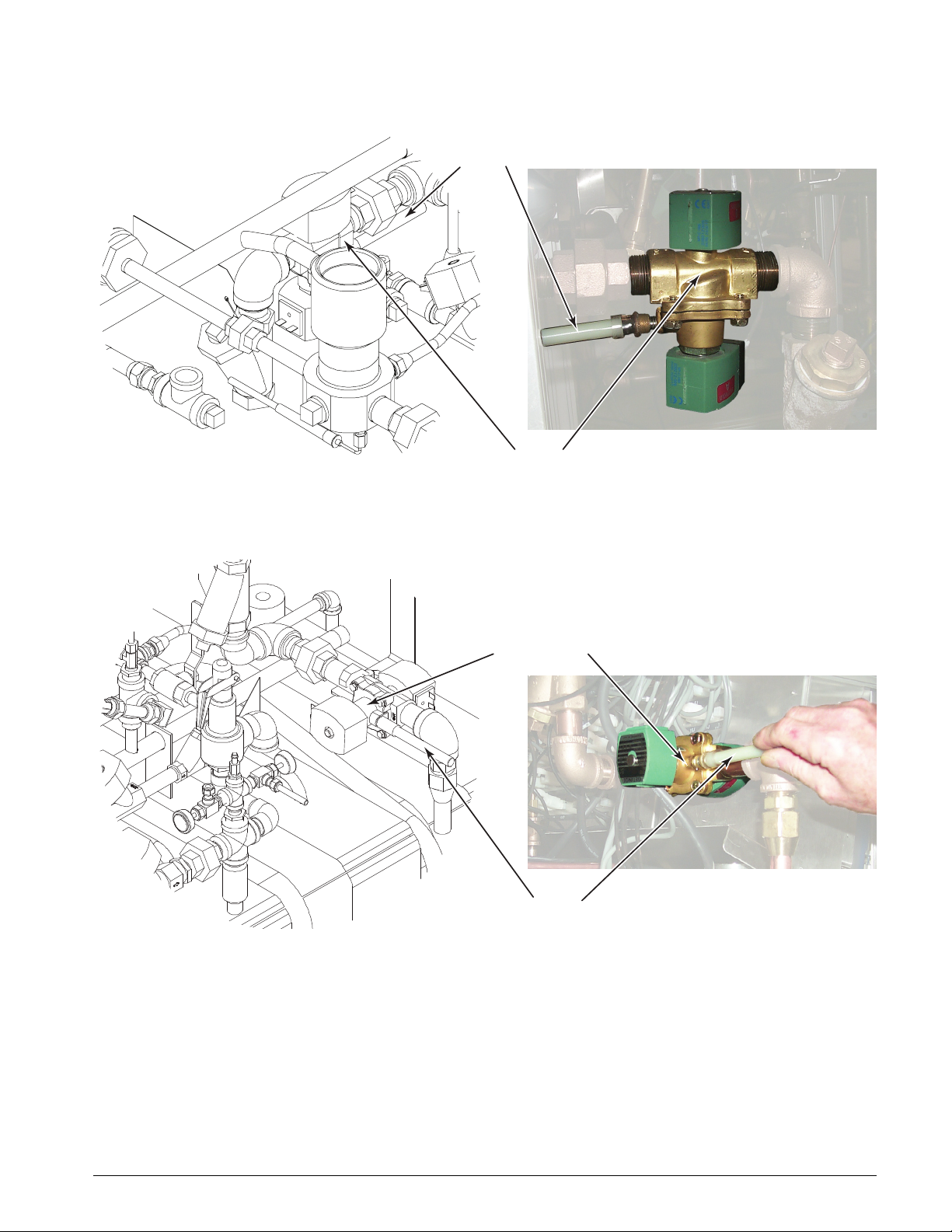
633HC Steam Sterilizer
Water to Ejector
Solenoid Valve
WS-0407-633
Handle
REMOTE END
BELOW CHAMBER
Handle
Water to Ejector
Solenoid Valve
WS-0118-633
CONTROL END
ABOVE CHAMBER
FIGURE 4–23. WATER TO EJECTOR SOLENOID VALVE (26-INCH
UNIT)
FIGURE 4–24. WATER TO EJECTOR SOLENOID VALVE (39- AND 51INCH UNITS)
3. Turn the water to ejector valve ON by pushing the white handle IN and
rotating it CLOCKWISE approximately 1/4 turn to the open position
indicated on the valve housing.
The water flow creates a vacuum to retract the gasket.
USR 61301607026 Rev B US 4–47
Page 100

Operation
Handle
(open position)
Steam to Door(s) Valve
WS-0408-633
Handle
(closed position)
CONTROL END
ABOVE CHAMBER
Handle
(open position)
Steam to Door(s) Valve
WS-0409-633
Handle
(closed position)
CONTROL END
ABOVE CHAMBER
FIGURE 4–25. STEAM TO DOOR(S) VALVE (26-INCH UNIT)
FIGURE 4–26. STEAM TO DOOR(S) VALVE (39- AND 51-INCH UNITS)
NOTE
The STEAM TO DOOR(S) valve is located in the service area on the left side
of the sterilizer above the chamber.
4. Locate the manual valve labeled “STEAM TO DOOR(S).”
5. CLOSE the valve by rotating the handle CLOCKWISE.
This turns OFF the steam supply to the door gasket.
4–48 USR 61301607026 Rev B US
 Loading...