

INSTALLATION
INSTRUCTIONS
Washer disinfector
46-2,46-4,46-5
Mfg. no.. SEV0632001-
5018606-00 Rev.C

2
Contents
Contents
Safety regulations _________________________________________________ 3
The machine must be assembled and installed by ___________________ 3
When the work is complete, check that _____________________________ 3
Product liability __________________________________________________ 3
Isolator switch ___________________________________________________ 3
Attention symbols _______________________________________________ 3
Installation ________________________________________________________ 4
Wall-mounted model _____________________________________________ 5
Free-standing model _____________________________________________ 6
Connecting electric power ________________________________________ 7
Connecting water, steam, waste and dryer __________________________ 8
Function check _________________________________________________ 10
Technical data ____________________________________________________ 12
Alternative connection arrangements ______________________________ 15
5018606-00 Rev.C Edition 0704
Installation instructions
Safety regulations
Safety regulations
This machine has been designed with a number of built-in safety devices. To avoid
injury, it is very important that these safety devices are not bypassed and thus
disabled.
The machine must be assembled and installed by
• qualified personnel.
• in accordance with current local regulations and rules.
When the work is complete, check that
• all parts have been installed in accordance with the installation instructions
• all screws have been properly tightened
• there are no sharp edges on any parts that may come into contact with people
• all hoses, pipes and connections are intact and free from defects
• all the functions of the machine are working properly. Adjust if necessary.
3
Product liability
Any modification or incorrect use of the equipment without the approval of Getinge
Disinfection AB invalidates Getinge Disinfection AB’s product liability.
Isolating device
The machine should be fitted with a separate isolating device in the electric power
supply. The isolating device must be easily accessible on a wall close to the
machine.
Attention symbols
Some of the warnings, instructions and advice in this manual are so important that
we use special symbols to draw attention to them. The symbols used are as follows:
This symbol indicates a warning in the text of the manual. The nature of the
hazard that the warning relates to is such that it may result in more or less
severe injury and in certain cases mortal danger.
It also highlights warnings to avoid damage to equipment.
5018606-00 Rev.C
Installation instructions
Edition 0704

4
Installation
• The floor where the machine is to stand must be flat and level within ±5 mm.
• Pull the machine (on a transport pallet) to the location where it will be installed.
• Lift the machine off the pallet.
• Position the machine at the chosen location and adjust the feet so that the
machine is stable. The adjusting feet must be screwed out not more than
110 mm from the underside of the machine (the 100 mm dimension on Figure 3
can be ±10 mm). There must be clear space for loading/unloading the machine
1700 mm in front of the door(s) of the machine.
• Place a foot plate under each adjusting screw. Foot plates are supplied in a
plastic bags in the chamber of the machine.
Level the machine
with a spirit level.
Installation
V1634
Figure 1. Adjustment
• Using a spirit level, check as shown in Figure 1 that the machine is level within ±2 mm,
• Free-standing model: prepare a water supply and a waste connection by breaking
out suitable prepared openings in the rear cover plate panel of the machine.
• If the machine is to be moved with a pallet truck, the forks of the pallet truck
must be positioned as shown in Figure 2 to avoid damage to the machine.
Bottom frame
Adjusting screws
Foot plate
V318
Figure 2. Positioning the pallet truck forks.
5018606-00 Rev.C Edition 0704
Installation instructions
Installation
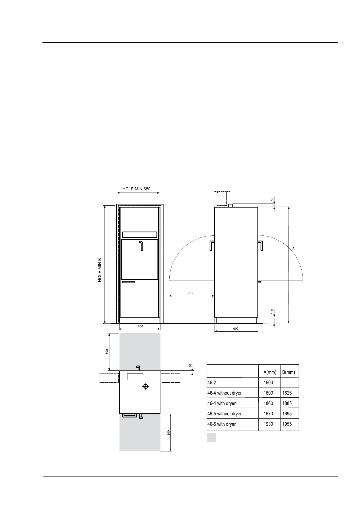
Wall-mounted model
• If the machine has double doors and is to be mounted in a wall, the distance
between machine and wall must be 15 mm.
• If more than one machine is to be installed next to each other they must be
adjusted to the same height on installation.
• Where a plinth plate is used, the height from the floor to the underside of the
machine must be at least.
• Set the machine horizontal with a spirit level on the side of the machine and
adjust with the feet. The adjusting feet must be unscrewed not more than 110
mm from the underside of the machine.
• For the loading trolley to work in all the machines, the floor in front of them must
be flat and level.
5
5018606-00 Rev.C
Service area
Figure 3. Mounting in a wall
Installation instructions
Edition 0704

6
Free-standing model
• Secure the tipover protection to the machine with the screws, then secure the
backplate.
• Fix the tipover protection to the wall with screws.
Installation
Tipover protection
V1640
Figure 4. Tipover protection
• Check that the door and the two side plates are parallel.
If not:
• Open the lower door and adjust the machine.
• To adjust the machine to the left, turn the nuts to the left; to adjust the machine
to the right, turn the nuts to the right.
The door and the
two side plates
must be parallel.
V1639
Fig 5. Diagonal adjustment
5018606-00 Rev.C Edition 0704
Installation instructions

Installation
Connecting electric power
Installation may only be done by authorized personnel.
Connect electric power to the machine as follows:
• Install the machine in accordance with installation category CAT II.
• Connect the power supply to the electrical connections of the machine; see the
diagram with alternative connection arrangements.
For easier servicing and maintenance, the supply to the machine must be fitted
with an isolator switch with a 3 mm isolating gap. The device must be located in
an easily accessible position close to the machine.
• Open the lower hatch.
• Remove the inner safety plate to access the electrical box.
It is important that the connection has the correct overcurrent protection. The
correct fuse rating is stated on the type plate.
7
Isolating device
Electrical box
V1638
Figure 6 Electrical connection (see electrical diagram in the service instructions)
Terminal block
5018606-00 Rev.C
Figure 7. Electrical box
Installation instructions
Edition 0704

8
Connecting water, steam, waste and dryer
Installation may only be done by authorized personnel.
• Provide separate shutoff valves on the water and (if used) steam lines. Flush out
the water and steam pipes that are to be connected to the machine, to prevent
clogging of filters and valves.
• Connect the disinfector to cold and hot water and to steam and condensate
connections, if used. The connections must meet the following requirements:
Connection Pressure Consumption Flow rate
Cold water 1/2" (15 mm) female 100-800 kPa approx 15 liters/phase min 20 l/min
Hot water 1/2" (15 mm) female 100-800 kPa approx 15 liters/phase min 20 l/min
Dist. water/ 3/4" (20 mm) male 50-900 kPa* approx 15 liters/phase min 20 l/min
De-ion. water
Steam 1/2" (15 mm) female 300-500kPa 0.5 kg/min
Installation
(300 kPa)
V1632
Condensate 1/2" (15 mm) female
* Where the pressure is lower than 50 kPa a separate feeder pump must be used. Where a separate
feeder pump is used, the pressure must not exceed 60 kPa (risk of serious damage to the pump).
• PTFE tape is recommended for sealing the connections.
NOTE:
Distilled or de-ionised water must have a conductivity of less than 40 μS/cm.
1. Distilled/de-ionized water 160 mm above
the floor*.
2. Hot water, 245 above the floor, flexible
hose, L= 1500 mm supplied*.
3. Cold water, 305 mm above the floor,
flexible hose, L= 1500 mm supplied*.
4. Electrical connection , 500 mm above floor.
5. Waste, adjustable within this range
(C/L of outlet pipe)
6. Steam connection, 200 mm above floor.
7. Condensate connection, 200 mm above
floor.
8. Dryer, exhaust air, at roof, 46-4, 46-5
9. Dryer, exhaust air, at roof, 46-2
10. Distilled/de-ionized water without
pressure, 200 mm above the floor.
* A flexible hose can be connected from
above directly to the valve 1400 mm above
the floor. A hole for the hose in the ceiling or
cover plate must be made on site.
Figure 8. Connecting water, steam, waste and dryer
5018606-00 Rev.C Edition 0704
Installation instructions

Installation
9
Leave this air
hole open
avlopp_46
Figure 9. Connecting waste and draft traps
• Connect the disinfector to a waste outlet with a capacity of at least 50 litres/min.
The trap can be connected towards the rear or downwards, as shown in
Figure 8. Waste diameter: 50 mm.
• Connect air exhaust from dryer (if the machine has a dryer). Air quantity approx
3
125 m
/h.
5018606-00 Rev.C
Installation instructions
Edition 0704

10
Function check
• Check that the machine is connected to the correct voltage and the waste,
water, steam and condensate connections are correctly connected. Open the
valves for water and steam.
• Fill the detergent and rinse aid containers and place alarm sensors in the
containers.
Machines with double doors have a system of interlocks to ensure that only one
door can be opened at a time.
If the soiled-side door cannot be opened, check that the clean-side door is
closed. The clean-side door can only be opened if the completed process has
been approved and the door on the soiled side is closed and locked.
• Place a wash rack in the wash chamber and close the door.
• Choose a program where dosing is done from all detergent and rinse-aid
containers and start the machine (see Instructions for use).
• Check that the machine draws water.
Note: If the machine has a distilled water pump, make sure that the pump has been filled
with water so that it can deliver enough pressure to open the distilled water valve.
Installation
NOTE:
On starting, there must be water in the circulation pump. If there is no water in the pump,
the shaft seal may suffer damage.
• Check that the circulation pump is rotating the right direction as indicated by the
arrow on the pump motor. If not, isolate the power, change the phase sequence
at the electrical connections and restart the machine.
V1426
Figure 10. Circulation pump
• Check that the dosing pumps work at the right time in accordance with the
program description in the instructions for use and that detergent is drawn off.
• While the program is running, check that the door(s) cannot be opened.
5018606-00 Rev.C Edition 0704
Installation instructions

Installation
11
• On a machine with manual double doors, check the door locking function when
the program is complete as follows:
- Check that the soiled-side door side cannot be opened.
- Open and close the clean side door.
- Open the soiled-side door.
- Check that the clean side door cannot be opened.
• Check that there are no water or steam leaks. If necessary, retighten water,
steam and waste connections.
5018606-00 Rev.C
Installation instructions
Edition 0704

12
Technical data
Dimensions
Outside dimensions
Weight Total Loading per machine foot
Machine 46-2 without dryer 150 kg 50 kg
Machine 46-2 with dryer 150 kg 50 kg
Machine 46-4 without dryer 150 kg 55 kg
Machine 46-4 with dryer 180 kg 65 kg
Machine 46-5 without dryer 155 kg 60 kg
Machine 46-5 with dryer 185 kg 70 kg
Width 650 mm
Depth 690 mm
Height
Machine 46-2 without dryer 1600 mm
Machine 46-2 with dryer 1600 mm
Machine 46-4 without dryer 1600 mm
Machine 46-4 with dryer 1860 mm
Machine 46-5 without dryer 1670 mm
Machine 46-5 with dryer 1930 mm
Technical data
incl. water and load
Chamber size
Machine 46-2, 46-4 Chamber depth =590 mm
Machine 46-5 Chamber height =660 mm
Chamber width =550 mm
Chamber depth =620 mm
Operational volume 201 liters
Total volume 280 liters
Chamber width = 550 mm
Chamber depth = 620 mm
Operational volume 225 liters
Total volume 305 liters
5018606-00 Rev.C Edition 0704
Installation instructions

Technical data
Connections
Water consumption
about 15-19 liters/phase
Cold water
Water quality Driinking water with max 5 °dH
Connection 15 (1/2") mm
Pressure 100-800 kPa
Flow rate, min 20 l/min
Hot water
Water quality Preheated drinking water with max 5 °dH
Temperature 45-60 °C (113 - 140 °F)
Connection 15 (1/2") mm
Pressure 100-800 kPa
Flow rate, min. 20 liters/min
13
Dist./De-ion. water
Temperature, max 90 °C (194 °F)
Connection 20 (3/4") mm
Pressure 50-800 kPa. Where the pressure is lower than 100 kPa, a separate
Flow rate, min 20 liters/min
The maximum conductivity is determined by the desired washing result.
Steam
Temperature, max 160 °C (320 °F)
Connection 15 (1/2") mm
Pressure 300-500 kPa
Consumption 0.5 kg/min at 300 kPa
Waste, water
ø 50 mm (2")
Capacity 50 liters/min
pressure booster pump must be connected. This is available as an
option. Where a separate feeder pump is used, the pressure must
not exceed 60 kPa (risk of serious damage to the pump).
Waste, air
5018606-00 Rev.C
ø 63 mm
Capacity 125-150m3/h, 35 °C (95 °F)
Humidity 100% 40 sec< 40% after 2 min.
Installation instructions
Edition 0704

14
Other points
Max outside temperature
50 °C (122 °F)
Sound level
Table 1
Calculated sound power level Lw for the test object, db ref 1 pW.
Octave band frequency (Hz) 12 5 250 50 0 1000 2000 4000 8000 LwA LwAFmax
Correction terms (Kok) 63 67 62 59 58 57 54 66 83
The calculated sound power level implies different sound levels LpA in different types of space. With a larger
room volume, the sound level decreases slightly and with a smaller room level it increases slightly. Table 2 below
shows three example of what to expect in practice.
Table 2
Calculated sound level LpA for the test object in a 70m3 room, db ref 20 μPa.
Type of room Description Operator position* 3 meters f rom
the machine
Hard to sound All surfaces of tile, plaster, concrete or similar, ie no
sound absorbing surfaces and no furniture 65 65
Normally-damped Some sound absorption in the form of furniture and textiles. 61 60
Damped Full-cover ceiling absorbent and some furnishing with
tables, chairs and textiles. 58 56
* Operator position means 1 meter from the machine and 1.5 meters above the floor. All values are for one
machine.
Electrical connections
See Alternative connection arrangements
Overcurrent protection as per Curve C
Heat dissipation to the room
Max 2000W (hot air during drying).
Heat radiation to the room
Max 1100W (during disinfection at 90 °C (194 °F))
Circulation system
Design pressure 0.2 MPa
Working pressure max 0.1 MPa
Design temperature 100 °C (212 °F)
Working temperature max 93 °C (200 °F)
Environmental requirements:
Air humidity max 80% at 31°C (87 °F)
Room temperature 5 - 40 °C (41 - 104 °F)
Degree of protection
IP21
5018606-00 Rev.C Edition 0704
Installation instructions

Alternative connection arrangements
Alternative connection arrangements
46-5
Electric heater
46-4
Electric heater
15
46-2
Electric heater
46-5
Steam heater
with dryer
46-4
Steam heater
with dryer
46-5
Steam heater
without dryer
46-4
Steam heater
without dryer
5018606-00 Rev.C
Installation instructions
Edition 0704

This product is manufactured by:
GETINGE DISINFECTION AB, Ljungadalsgatan 11, Box 1505, 351 15 Växjö, Sweden
 Loading...