


APPARECCHIATURA ELETTRONICA PER CANCELLI SCORREVOLI 230V
CONTROL BOARD FOR 230V SLIDING GATES
PLATINE ELECTRONIQUE POUR PORTAILS COULISSANTS 230V EQUIPO ELECTRÓNICO PARA PORTONES CORREDIZOS 230V ELEKTRONISCHES GERÄT FÜR SCHIEBETORE 230V
SPRINT 382
ISTRUZIONI PER L’USO – NORME DI INSTALLAZIONE
USE AND INSTALLATION INSTRUCTIONS
INSTRUCTIONS POUR L’EMPLOI – NORMES D’INSTALLATION INSTRUCCIONES PARA EL USO – NORMAS DE INSTALACIÓN BETRIEBSANLEITUNG - INSTALLATIONSVORSCHRIFTEN
AVVERTENZE PER L’INSTALLATORE
OBBLIGHI GENERALI PER LA SICUREZZA
1)ATTENZIONE! È importante per la sicurezza delle persone seguire attentamente tutta l’istruzione. Una errata installazione o un errato uso del prodotto può portare a gravi danni alle persone.
2)Leggere attentamente le istruzioni prima di iniziare l’installazione del prodotto.
3)I materiali dell’imballaggio (plastica, polistirolo, ecc.) non devono essere lasciati alla portata dei bambini in quanto potenziali fonti di pericolo.
4)Conservare le istruzioni per riferimenti futuri.
5)Questo prodotto è stato progettato e costruito esclusivamente per l’utilizzo indicatoinquestadocumentazione.Qualsiasialtroutilizzononespressamente indicato potrebbe pregiudicare l’integrità del prodotto e/o rappresentare fonte di pericolo.
6)GENIUS declina qualsiasi responsabilità derivata dall’uso improprioodiverso da quello per cui l’automatismo è destinato.
7)Noninstallarel’apparecchioinatmosferaesplosiva:lapresenzadigasofumi infiammabili costituisce un grave pericolo per la sicurezza.
8)Gli elementi costruttivi meccanici devono essere in accordo con quanto stabilito dalle Norme EN 12604 e EN 12605.
Per i Paesi extra-CEE, oltre ai riferimenti normativi nazionali, per ottenere un livello di sicurezza adeguato, devono essere seguite le Norme sopra riportate.
9)GENIUS non è responsabile dell’inosservanza della Buona Tecnica nella costruzione delle chiusure da motorizzare, nonché delle deformazioni che dovessero intervenire nell’utilizzo.
10)L’installazione deve essere effettuata nell’osservanza delle Norme EN 12453 e EN 12445. Il livello di sicurezza dell’automazione deve essere C+E.
11)Primadieffettuarequalsiasiinterventosull’impianto,toglierel’alimentazione elettrica.
12)Prevedere sulla rete di alimentazione dell’automazione un interruttore onnipolare con distanza d’apertura dei contatti uguale o superiore a 3 mm. Èconsigliabilel’usodiunmagnetotermicoda6Aconinterruzioneonnipolare.
13)Verificare che a monte dell’impianto vi sia un interruttore differenziale con soglia da 0,03 A.
14)Verificare che l’impianto di terra sia realizzato a regola d’arte e collegarvi le parti metalliche della chiusura.
15)L’automazione dispone di una sicurezza intrinseca antischiacciamento costituita da un controllo di coppia. E'comunque necessarioverificarne lasogli di intervento secondo quanto previsto dalle Norme indicate al punto 10.
16)I dispositivi di sicurezza (norma EN 12978) permettono di proteggere eventuali aree di pericolo da Rischi meccanici di movimento, come ad Es. schiacciamento,convogliamento,cesoiamento.
17)Per ogni impianto è consigliato l’utilizzo di almeno una segnalazione luminosanonchédiuncartellodisegnalazionefissatoadeguatamentesullastruttura dell’infisso, oltre ai dispositivi citati al punto “16”.
18)GENIUSdeclinaogniresponsabilitàaifinidellasicurezzaedelbuonfunzionamentodell’automazione,incasovenganoutilizzaticomponentidell’impianto non di produzione GENIUS.
19)Per la manutenzione utilizzare esclusivamente parti originali GENIUS.
20)Non eseguire alcuna modifica sui componenti facenti parte del sistema d’automazione.
21)L’installatore deve fornire tutte le informazioni relative al funzionamento manuale del sistema in caso di emergenza e consegnare all’Utente utilizzatore dell’impianto il libretto d’avvertenze allegato al prodotto.
22)Non permettere ai bambini o persone di sostare nelle vicinanze del prodotto duranteilfunzionamento.
23)Tenere fuori dalla portata dei bambini radiocomandi o qualsiasi altro datore di impulso, per evitare che l’automazione possa essere azionata involontariamente.
24)Il transito tra le ante deve avvenire solo a cancello completamente aperto.
25)L’Utente utilizzatore deve astenersi da qualsiasi tentativo di riparazione o d’intervento diretto e rivolgersi solo a personale qualificato.
26)Tutto quello che non è previsto espressamente in queste istruzioni non è permesso
IMPORTANT NOTICE FOR THE INSTALLER
GENERAL SAFETY REGULATIONS
1) ATTENTION! To ensure the safety of people, it is important that you read all the following instructions. Incorrect installation or incorrect use of the product could cause serious harm to people.
2)Carefully read the instructions before beginning to install the product.
3)Do not leave packing materials (plastic, polystyrene, etc.) within reach of children as such materials are potential sources of danger.
4)Store these instructions for future reference.
5)This product was designed and built strictly for the use indicated in this documentation.Anyotheruse,notexpresslyindicatedhere,couldcompromise the good condition/operation of the product and/or be a source of danger.
6)GENIUS declines all liability caused by improper use or use other than that for whichtheautomatedsystemwasintended.
7)Do not install the equipment in an explosive atmosphere: the presence of inflammable gas or fumes is a serious danger to safety.
8)The mechanical parts must conform to the provisions of Standards EN 12604 and EN 12605.
For non-EU countries, to obtain an adequate level of safety, the Standards mentionedabovemustbeobserved,inadditiontonationallegalregulations.
9)GENIUS is not responsible for failure to observe Good Technique in the construction of the closing elements to be motorised, or for any deformation that may occur during use.
10)TheinstallationmustconformtoStandardsEN12453andEN12445.Thesafety level of the automated system must be C+E.
11)Before attempting any job on the system, cut out electrical power.
12)The mains power supply of the automated system must be fitted with an allpole switch with contact opening distance of 3mm or greater. Use of a 6A thermal breaker with all-pole circuit break is recommended.
13)Make sure that a differential switch with threshold of 0.03 A is fitted upstream of the system.
14)Make sure that the earthing system is perfectly constructed, and connect metal parts of the means of the closure to it.
15)Theautomatedsystemissuppliedwithanintrinsicanti-crushingsafetydevice consisting of a torque control. Nevertheless, its tripping threshold must be checked as specified in the Standards indicated at point 10.
16)The safety devices (EN 12978 standard) protect any danger areas against mechanical movement Risks,suchascrushing,dragging,andshearing.
17)Use of at least one indicator-light is recommended for every system, as well as a warning sign adequately secured to the frame structure, in addition to the devices mentioned at point “16”.
18)GENIUS declines all liability as concerns safety and efficient operation of the automatedsystem,ifsystemcomponentsnotproducedbyGENIUSareused.
19)For maintenance, strictly use original parts by GENIUS.
20)Do not in any way modify the components of the automated system.
21)The installer shall supply all information concerning manual operation of the systemincaseofanemergency,andshallhandovertotheuserthewarnings handbooksuppliedwiththeproduct.
22)Do not allow children or adults to stay near the product while it is operating.
23)Keep remote controls or other pulse generators away from children, to prevent the automated system from being activated involuntarily.
24)Transit through the leaves is allowed only when the gate is fully open.
25)The user must not attempt any kind of repair or direct action whatever and contact qualified personnel only.
26)Anything not expressly specified in these instructions is not permitted.
CONSIGNES POUR L'INSTALLATEUR
RÈGLES DE SÉCURITÉ
1)ATTENTION! Il est important, pour la sécurité des personnes, de suivre à la lettre toutes les instructions. Une installation erronée ou un usage erroné du produit peut entraîner de graves conséquences pour les personnes.
2)Lire attentivement les instructions avant d'installer le produit.
3)Lesmatériauxd'emballage(matièreplastique,polystyrène,etc.)nedoivent pas être laissés à la portée des enfants car ils constituent des sources potentielles de danger.
4)Conserver les instructions pour les références futures.
5)Ceproduit aétéconçuetconstruitexclusivementpourl'usage indiquédans cette documentation. Toute autre utilisation non expressément indiquée pourrait compromettre l'intégrité du produit et/ou représenter une source dedanger.
6)GENIUS décline toute responsabilité qui dériverait d'usage impropre ou différent de celui auquel l'automatisme est destiné.
7)Ne pas installer l'appareil dans une atmosphère explosive: la présence de gaz ou de fumées inflammables constitue un grave danger pour la sécurité.
8)LescomposantsmécaniquesdoiventrépondreauxprescriptionsdesNormes EN 12604 et EN 12605.
Pour les Pays extra-CEE, l'obtention d'un niveau de sécurité approprié exige non seulement le respect des normes nationales, mais également le respect desNormessusmentionnées.
9)GENIUSn'estpasresponsabledunon-respectdelaBonneTechniquedansla construction des fermetures à motoriser, ni des déformations qui pourraient intervenir lors de l'utilisation.
10)L'installation doit être effectuée conformément aux Normes EN 12453 et EN 12445. Le niveau de sécurité de l'automatisme doit être C+E.
11)Couper l'alimentation électrique avant toute intervention sur l'installation.
12)Prévoir, sur le secteur d'alimentation de l'automatisme, un interrupteur omnipolaireavecunedistanced'ouverturedescontactségaleousupérieure à 3 mm. On recommande d'utiliser un magnétothermique de 6A avec interruption omnipolaire.
13)Vérifier qu'il y ait, en amont de l'installation, un interrupteur différentiel avec un seuil de 0,03 A.
14)Vérifier que la mise à terre est réalisée selon les règles de l'art et y connecter les pièces métalliques de la fermeture.
15)L'automatisme dispose d'une sécurité intrinsèque anti-écrasement, formée d'un contrôle du couple. Il est toutefois nécessaire d'en vérifier le seuil d'intervention suivant les prescriptions des Normes indiquées au point 10.
16)Les dispositifs de sécurité (norme EN 12978) permettent de protéger des zones éventuellement dangereuses contre les Risques mécaniques du mouvement,commel'écrasement,l'acheminement,lecisaillement.

ENGLISH
CONTROL BOARD SPRINT 382
1. WARNINGS |
3. LAYOUT AND COMPONENTS |
Important: Before attempting any work on the control board (connections, maintenance), always turn off power.
-Install,upstreamofthesystem,adifferentialthermalbreakerwith adequate tripping threshold.
-Connect the earth cable to the appropriate terminal on the J7 connector of the equipment (see fig.2).
-Always separate power cables from control and safety cables (push-button, receiver, photocells, etc.). To avoid any electric noise, use separate sheaths or a shielded cable (with earthed shield).
2.TECHNICAL SPECIFICATIONS
Power supply |
230 V~ ( +6% -10%) - 50 Hz |
Absorbed power |
10 W |
Motor max. load |
1000 W |
Accessories max. load |
0,5 A |
Operating ambient temperature |
-20 °C +55 °C |
Protection fuses |
2 (see fig. 1) |
Function logics |
Automatic / "Stepped" automatic / |
Semi-automatic / Safety devices / Semi-automatic B / |
|
Dead-man C / "Stepped" semi-automatic / Mixed Log. B+C |
|
|
|
Work time |
Programmable (from 0 to 4 min.) |
|
|
|
|
|
|
|
|
|
|
|
|
|
|
|
|
|
|
|
|
|
|
|
DL |
|
|
|
|
|
|
|
|
|
|
|
|
F2 |
|
|
|
|
|
|
|
|
|
|
|
|
|
|
|
|
|
|
|
|
|
|
|
|
|
|
|
|
|
|
|
|
|
|
|
|
|
|
|
|
|
|
|
|
|
|
|
|
|
+ |
|
|
– |
|
F |
|
|
|
|
|
|
|
|
|
|
|
|
|
|
|
|
|
|
|
|
|
|
|
|
|
|
|
|
|
|
F1 |
|
|
|
|
|
|
|
|
|
|
|
|
|
|
|
|
|
|
|
|
|
|
|
|
|
|
|
|
|
|
|
|
|
|
|
|
|
|
|
|
|
|
|
|
|
|
|
|
|
|
|
|
|
|
|
|
|
|
|
|
|
|
|
|
|
|
J2 |
|
|
Led |
|
|
|
|
|
|
|
|
|
|
|
|
|
|
|
||
|
|
|
|
|
|
|
|
|
|
|
|
|
|
|
|
|
|
|
|
|
|
|
|
|
|
|
|
|
|
|
|
|
|
|
|
|
|
|
|
|
|
|
|
|
|
|
|
|
|
|
|
|
|
|
|
|
|
|
|
|
|
|
|
|
|
|
|
|
|
|
|
|
|
|
|
|
|
|
|
|
|
|
|
|
|
|
|
|
|
|
|
|
|
|
|
|
|
|
|
|
|
|
|
|
|
|
|
|
|
|
|
|
|
|
|
|
|
|
|||||||
J5 |
J3 |
|
|
|
|
|
|
|
|
|
|
|
|
|
|
|
|
|
|
|
|
|
|
|
|
|
|||||||||||||||
|
|
|
J1 |
|
|
|
|
|
|
|
|
|
J6 |
|
|
|
J7 |
|||
|
|
|
|
|
|
|
|
|
|
|
|
|
|
|||||||
|
|
|
|
|
|
|
|
|
|
|
|
|
|
|
|
|
||||
Fig. 1
Pause time |
|
|
Programmable (from 0 to 4 min.) |
|
|
|
DL |
|
||||||
Thrust force |
|
|
|
Adjustable over 50 levels |
|
|
|
|
||||||
|
|
|
|
|
|
Led |
|
|||||||
Terminal board |
inputs |
Open / Partial opening / Safety devices at opng. / |
|
|
|
|||||||||
|
Safety devices at clsng. / Stop / Edge / Power supply + Earth |
|
J1 |
|
||||||||||
On-connector inputs |
Opening and closing limit-switches |
/ Encoder |
|
J2 |
|
|||||||||
Terminal board outputs |
Flashing lamp - Motor - 24 Vdc accessories power |
|
||||||||||||
J3 |
|
|||||||||||||
|
supply - 24 Vdc indicator-light / Timed output. - Fail safe |
|
|
|||||||||||
|
J5 |
|
||||||||||||
Rapid connector |
5-pin card connection for radio-receiver module |
|
|
|||||||||||
Programming |
3 keys (+, -, F) and display, "basic" or "advanced" mode |
J6 |
|
|||||||||||
Basic mode programmable functions |
Function logic - Pause time - Thrust |
|
|
|
J7 |
|
||||||||
|
|
|
|
Force - Gate direction |
|
|
|
F1 |
|
|||||
Advanced mode programmable functions |
Torque at initial thrust - Braking - |
|
||||||||||||
F2 |
|
|||||||||||||
|
Fail safe - Pre-flashing - Indicator-light/Timed output - |
|
||||||||||||
|
|
Opening and closing safety devices logic - |
F |
|
||||||||||
|
|
Encoder - Decelerations - Partial opening time - |
|
|||||||||||
|
|
– |
|
|||||||||||
|
|
Work time - Assistance request - Cycle counter |
|
|||||||||||
4. ELECTRIC CONNECTIONS |
|
|
|
|
|
|
|
|
|
+ |
|
|||
|
|
|
|
|
|
|
|
|
|
|
|
|
|
|
|
|
|
|
|
|
|
|
|
|
|||||
SIGNALLINGANDPROGRAMMINGDISPLAY
INPUTS STATUS CONTROL LED
LOW VOLTAGE TERMINAL BOARD
CONNECTORFORRADIO-RECEIVERMODULE
ENCODER CONNECTOR
LIMIT -SWITCH CONNECTOR
MOTORS AND FLASHING LAMP CONNECTION TERMINAL BOARD
230 VAC POWER SUPPLY TERMINAL BOARD
MOTORSANDTRANSFORMERPRIMARYWINDINGFUSE(F5A)
LOW VOLTAGE AND ACCESSORIES FUSE (T 800mA)
"F" PROGRAMMING PUSH-BUTTON
"–" PROGRAMMING PUSH-BUTTON
"+" PROGRAMMING PUSH-BUTTON
|
|
|
|
|
|
|
|
|
|
|
|
||||
|
|
|
|
|
|
|
|
|
|
|
|||
|
|
|
|
BLUE |
|
|
|
|
|
|
C |
|
|
|
|
|
24 Vdc |
M |
230 Vac |
|
|
|
|
|
max. 60W |
|
|
|
|
|
3 W |
|
|
|
|
|
|
|
|
|
230 Vac |
|
|
|
|
|
|
50 Hz |
|
|
For connection of the |
|
|
|
|
|
|
photocells and safety |
|
|
|
|
|
|
devices, see paragraph |
|
|
|
|
|
|
4.1. |
|
STOP |
|
|
|
|
|
|
|
|
|
|
ENCODER |
PARTIALLY OPEN |
|
|
|
Fig. 2 |
|
(optional) |
|
|
|
|
|
LIMIT-SWITCH |
|
TOTALLY OPEN |
NB.: The capacitor is supplied with the operator. |
|||
10
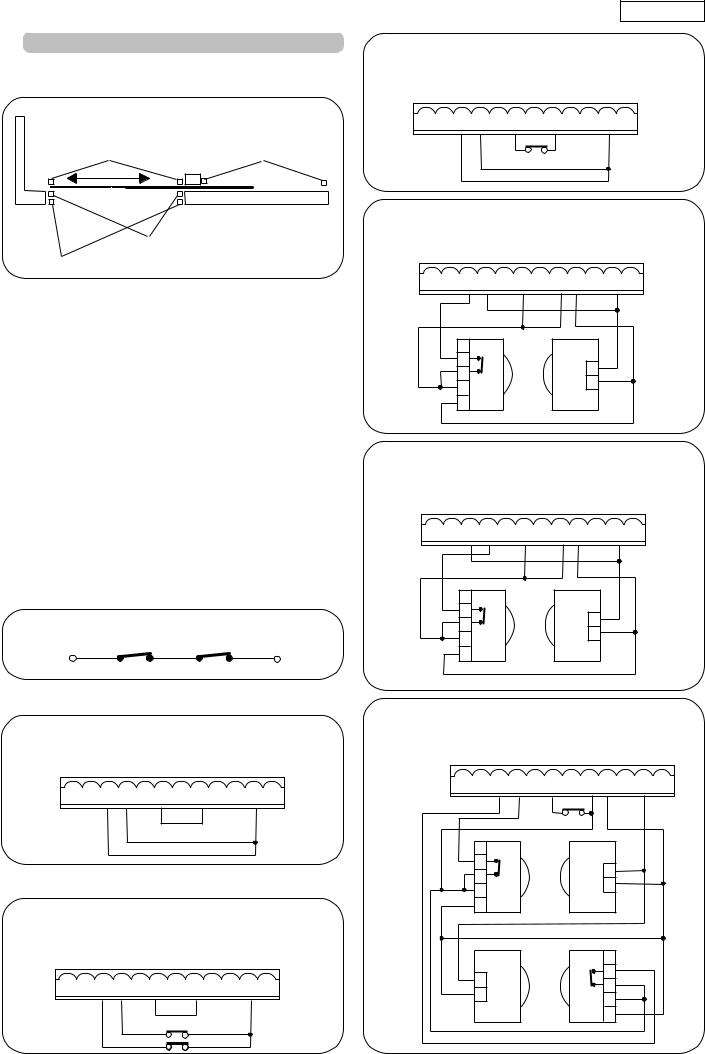
4.1.Connectionofphotocellsandsafetydevices
Before connecting the photocells (or other devices) we advise you to select the type of operation according to the movement area they have to protect (see fig.3):
Opening/closing |
Opening safety |
safety devices |
devices |
"Edge" safety devices
Closing safety device |
Fig. 3 |
Opening safety devices: they operate only during the gate opening movement and, therefore, they are suitable for protecting the area between the opening leaf and fixed obstacles (walls, etc) against the risk of impact and crushing.
Closing safety devices: they operate only during the gate closing movement and, therefore, they are suitable for protecting the closing area against the risk of impact.
Opening/closing safety devices: they operate during the gate opening and closing movements and, therefore, they are suitable for protecting the opening and closing areas against the risk of impact.
"Edge" safety devices: they operate during the gate opening and closing movements and, therefore, they are suitable for protecting the areas between the moving leaf and fixed obstacles (pillars, walls, etc) against the risk of shearing and dragging.
Encoder (optional): operates during the gate opening and closing movements and, therefore, it is suitable for protecting the opening and closing area against the risk of impact, crushing, shearing and dragging.
N.B. If two or more safety devices have the same function (opening, closing, opening and closing, edge), the contacts must be connected to each other in series (fig. 4).
N.C. contacts must be used.
Connection of two N.C. contacts in series (e.g. Photocells, Stop, Edge, etc.)
Fig. 4
N.B: If safety devices are not used, jumper connect the terminals as shown in fig. 5.
Connection of no safety device
|
|
|
|
|
|
|
|
|
|
|
|
|
|
|
|
|
Fig. 5
The most common photocell and safety device lay-outs are shown below (from fig. 6 to fig. 13).
Connection of a closing safety device and an opening safety device
|
|
|
|
|
|
|
|
|
|
|
|
|
|
|
|
|
Fig. 6
ENGLISH
Connection of an "edge" safety device
|
|
|
|
|
|
|
|
|
|
|
|
|
|
|
|
|
Fig. 7
Connection of a pair of photocells for opening
|
|
|
|
|
|
|
|
|
|
|
|
|
|
|
|
|
|
RX |
TX |
|
1 |
|
|
|
2 |
|
|
1 |
3 |
|
- |
|
|
+ |
|
|
4 |
- |
2 |
|
|
|
||
5 |
+ |
|
|
Fig. 8
Connection of a pair of closing photocells
|
|
|
|
|
|
|
|
|
|
|
|
|
|
|
|
|
|
RX |
TX |
|
1 |
|
|
|
2 |
|
|
1 |
3 |
|
- |
|
|
+ |
|
|
4 |
- |
2 |
|
|
|
||
5 |
+ |
|
|
Fig. 9
Connection of a pair of opening photocells, a pair of closing photocell and an edge safety device
|
|
|
|
|
|
|
|
|
|
|
|
|
|
|
|
|
|
RX CL |
TX CL |
|
1 |
|
|
|
2 |
|
|
1 |
3 |
|
- |
|
|
+ |
|
|
4 |
- |
2 |
|
|
|
||
5 |
+ |
|
|
TX OP |
RX OP |
|
|
|
|
|
1 |
1 |
|
|
2 |
- |
|
3 |
|
|
+ |
|
|
2 |
- |
4 |
|
|
|
||
|
|
+ |
5 |
Fig. 10
11
 Loading...