

Page 1
SETUP & OPERATION MANUAL
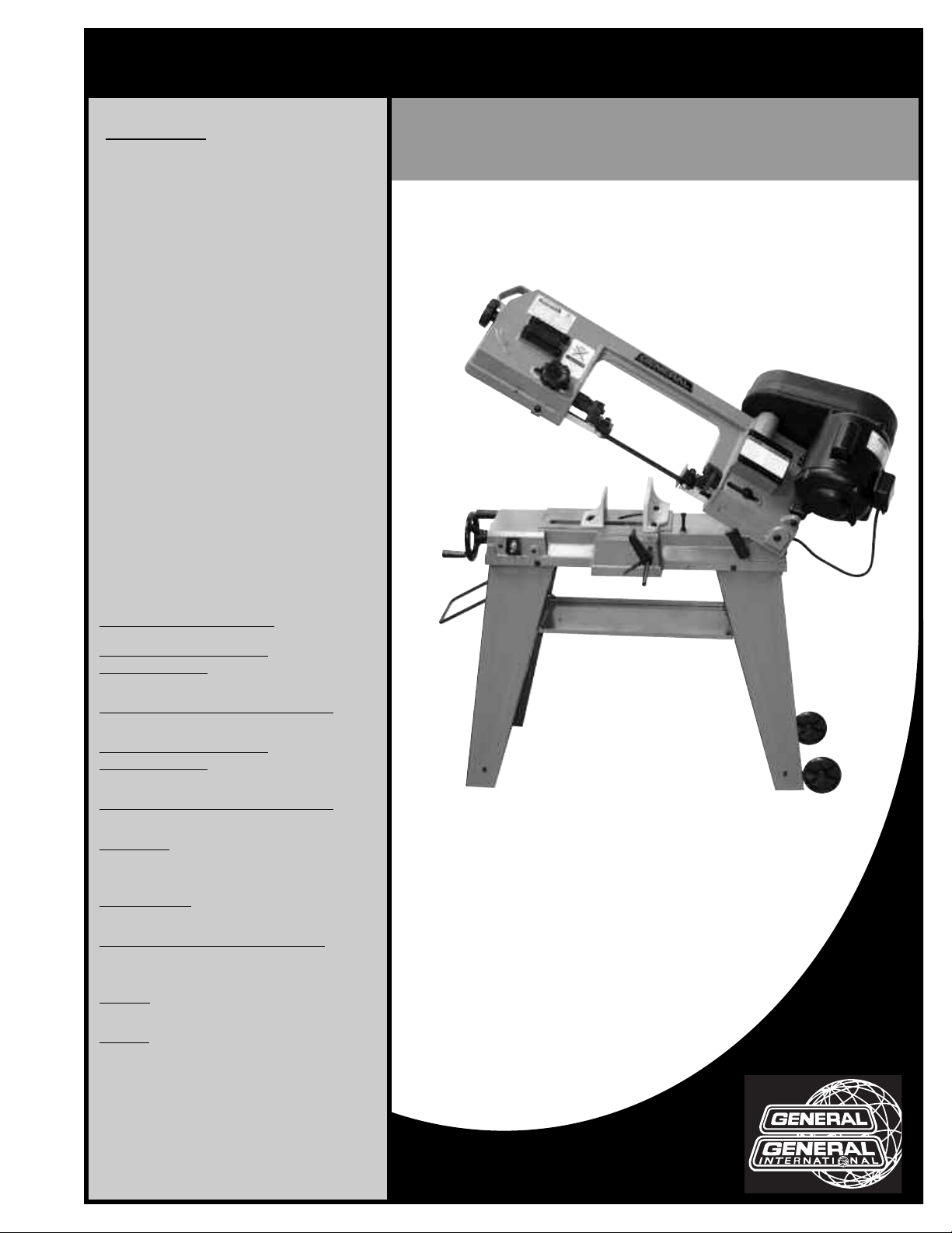
FEATURES
Horizontal or vertical cutting.
Convenient auxiliary table supports the
workpiece in vertical cutting mode.
Automatic shut off at the end of
cutting cycle.
Adjustable tension spring down feed
control.
Heavy-duty steel stand with tool tray
Stand mounted on 2 sturdy wheels for
ease of mobility.
Fully adjustable blade guide
bearings.
Three blade speeds to accommodate
a wide range of cutting needs.
Sturdy vise with 0 - 45° left swivel.
4 1/2" X 6" METAL CUTTING BANDSAW
SPECIFICATIONS
CUTTING CAPACITY AT 90º
(RECTANGULAR)
4” x 5 5/8” (102 x 145 mm)
CUTTING CAPACITY AT 90º (ROUND)
4 1/2” (112 mm)
CUTTING CAPACITY AT 45º
(RECTANGULAR)
2 3/8” x 4 1/2” (60 x 115 mm)
CUTTING CAPACITY AT 45º (ROUND)
2 3/8” (60 mm)
BLADE SIZE
1/2” x 0.025” x 64 1/2”
(12.7 x 0.64 x 1640 mm)
BLADE SPEEDS
80, 120 & 200 FPM (24, 37 & 61 MPM)
OVERALL DIMENSIONS (L X W X H)
40 1/2” x 18” x 54 1/4”
(1030 x 457 x 1375 mm)
MOTOR
1/2 HP, 115V, 1Ph, 6 A
WEIGHT
134 LBS (61 kg)
MODEL
#90-665 M1
VERSION 1 - November 28 2011
© Copyright General® International 2011
Page 2

GENERAL® INTERNATIONAL
8360 Champ-d’Eau, Montreal (Quebec) Canada H1P 1Y3
Telephone (514) 326-1161 • Fax (514) 326-5555 • www.general.ca
THANK YOU for choosing this General
®
International model 90-665 M1
4 1/2” x 6” metal cutting bandsaw. This metal cutting bandsaw has been carefully tested and
inspected before shipment and if properly used and maintained, will provide you with years
of reliable service. For your safety, as well as to ensure optimum performance and trouble-free
operation, and to get the most from your investment, please take the time to read this manual before assembling, installing and operating the unit.
The manual’s purpose is to familiarize you with the safe operation, basic function, and features
of this metal cutting bandsaw as well as the set-up, maintenance and identification of its parts
and components. This manual is not intended as a substitute for formal metalworking instruction, nor to offer the user instruction in the craft of metalworking. If you are not sure about the
safety of performing a certain operation or procedure, do not proceed until you can confirm,
from knowledgeable and qualified sources, that it is safe to do so.
Once you’ve read through these instructions, keep this manual handy for future reference.
Disclaimer: The information and specifications in this
manual pertain to the unit as it was supplied from the
factory at the time of printing. Because we are committed to making constant improvements, General
International reserves the right to make changes to
components, parts or features of this unit as deemed
necessary,without prior notice and without obligation to
install any such changes on previously delivered units.
Reasonable care is taken at the factory to ensure that
the specifications and information in this manual corresponds with that of the unit with which it was supplied.
However, special orders and “after factory” modifications may render some or all information in this manual
inapplicable to your machine. Further, as several gene-
®
rations of this model of metal cutting bandsaw and several versions of this manual may be in circulation, if you
own an earlier or later version of this unit, this manual
may not depict your machine exactly. If you have any
doubts or questions contact your retailer or our support
line with the model and serial number of your unit for
clarification.
Page 3

GENERAL®& GENERAL®INTERNATIONAL WARRANTY
All component parts of General®, General® International and Excalibur by General
International ® products are carefully inspected during all stages of production and each unit
is thoroughly inspected upon completion of assembly.
Limited Lifetime Warranty
Because of our commitment to quality and customer satisfaction, General® and General®
International agree to repair or replace any part or component which upon examination,
proves to be defective in either workmanship or material to the original purchaser for the life
of the tool. However, the Limited Lifetime Warranty does not cover any product used for profes-
sional or commercial production purposes nor for industrial or educational applications. Such
cases are covered by our Standard 2-year Limited Warranty only. The Limited Lifetime Warranty
is also subject to the “Conditions and Exceptions” as listed below.
Standard 2-Year Limited Warranty
All products not covered by our lifetime warranty including products used in commercial,
industrial and educational applications are warranted for a period of 2 years (24 months) from
the date of purchase. General® and General® International agree to repair or replace any
part or component which upon examination, proves to be defective in either workmanship or
material to the original purchaser during this 2-year warranty period, subject to the “conditions
and exceptions” as listed below.
To file a Claim
To file a claim under our Standard 2-year Limited Warranty or under our Limited Lifetime
Warranty, all defective parts, components or machinery must be returned freight or postage
prepaid to General® International, or to a nearby distributor, repair center or other location
designated by General® International. For further details call our service department at 1-888949-1161 or your local distributor for assistance when filing your claim.
Along with the return of the product being claimed for warranty, a copy of the original proof
of purchase and a “letter of claim” must be included (a warranty claim form can also be used
and can be obtained, upon request, from General® International or an authorized distributor)
clearly stating the model and serial number of the unit (if applicable) and including an explanation of the complaint or presumed defect in material or workmanship.
CONDITIONS AND EXCEPTIONS:
This coverage is extended to the original purchaser only. Prior warranty registration is not
required but documented proof of purchase i.e. a copy of original sales invoice or receipt
showing the date and location of the purchase as well as the purchase price paid, must be
provided at the time of claim.
Warranty does not include failures, breakage or defects deemed after inspection by General®
or General® International to have been directly or indirectly caused by or resulting from;
improper use, or lack of or improper maintenance, misuse or abuse, negligence, accidents,
damage in handling or transport, or normal wear and tear of any generally considered consumable parts or components.
Repairs made without the written consent of General® Internationallwill void all warranty.
Page 4

TABLE OF CONTENTS
Rules for safe operation . . . . . . . . . . . . . . .5
Electrical requirements . . . . . . . . . . . . . . .6
Grounding instructions . . . . . . . . . . . . . . . . . . . . . . .6
Circuit capacity . . . . . . . . . . . . . . . . . . . . . . . . . . . . .6
Extension cords . . . . . . . . . . . . . . . . . . . . . . . . . . . . .6
Identification of main parts
and components . . . . . . . . . . . . . . . . . . . .
Unpacking . . . . . . . . . . . . . . . . . . . . . . . . .8
List of contents . . . . . . . . . . . . . . . . . . . . . . . . . . . . . .8
Operating instructions . . . . . . . . . . . . . . .14
hecklist before starting . . . . . . . . . . . . . . . . . . . . .14
C
Holding different worpiece shapes in vise . . . . . .14
Maintenance . . . . . . . . . . . . . . . . . . . . . .14
Daily check . . . . . . . . . . . . . . . . . . . . . . . . . . . . . . .14
Montly check . . . . . . . . . . . . . . . . . . . . . . . . . . . . . .14
Cleaning . . . . . . . . . . . . . . . . . . . . . . . . . . . . . . . . . .14
7
Lubrication . . . . . . . . . . . . . . . . . . . . . . . . . . . . . . . .14
Trouble shooting . . . . . . . . . . . . . . . . .15-16
Placement within the shop /
Establishing a safety zone . . . . . . . . . . . . .
Assembly instructions . . . . . . . . . . . . . .9-10
Install the wheel to stand . . . . . . . . . . . . . . . . . . . . .9
Mount the carrying handle . . . . . . . . . . . . . . . . . . .9
Fix the support legs . . . . . . . . . . . . . . . . . . . . . . . . . .9
Install the tool tray . . . . . . . . . . . . . . . . . . . . . . . . . . .9
Fix the pulley cover . . . . . . . . . . . . . . . . . . . . . . . . . .9
Install the work stop . . . . . . . . . . . . . . . . . . . . . . . . . .9
Install the auxiliary table (for vertical cuts) . . . . .10
Basic adjustments & controls . . . . . . . .10-14
Connecting to a power source . . . . . . . . . . . . . . .10
On / off power switch . . . . . . . . . . . . . . . . . . . . . . .10
Adjusting the work stop . . . . . . . . . . . . . . . . . . . . .10
Adjusting the vive . . . . . . . . . . . . . . . . . . . . . . . . . .10
Blade speed . . . . . . . . . . . . . . . . . . . . . . . . . . . . . . .11
Changing blade speed . . . . . . . . . . . . . . . . . . . . .11
Blade selection . . . . . . . . . . . . . . . . . . . . . . . . . . . .11
Adjusting blade guides . . . . . . . . . . . . . . . . . . . . .11
Feed rate . . . . . . . . . . . . . . . . . . . . . . . . . . . . . . . . . .11
Horizontal cutting . . . . . . . . . . . . . . . . . . . . . . . . . . .12
Vertical cutting . . . . . . . . . . . . . . . . . . . . . . . . . . . . .12
Changing blade . . . . . . . . . . . . . . . . . . . . . . . . . . .12
Blade tension . . . . . . . . . . . . . . . . . . . . . . . . . . . . . .13
Squaring the blade . . . . . . . . . . . . . . . . . . . . . . . . .13
Blade guide bearings . . . . . . . . . . . . . . . . . . . . . . .13
Wiring diagram . . . . . . . . . . . . . . . . . . . .17
8
Parts list & diagrams . . . . . . . . . . . . . .18-19
Contact information . . . . . . . . . . . . . . . . .20
Page 5

RULES FOR SAFE OPERATION
To helpensure safe operation, please takea momentto learn the machine’s applicationsand limitations, as well as potential hazards. General® International disclaims any real or implied warranty and holds itself harmless for any injury that
may result from improper use of its equipment.
1. Do not operate this bandsaw when tired, distracted, or
under the effects of drugs, alcohol or any medication
that impairs reflexes or alertness.
2. The working area should be well lit, clean and free of
debris.
3. Keep children and visitors at a safe distance when the
bandsaw is in operation; do not permit them to operate the bandsaw.
4. Childproof and tamper proof your shop and all machinery with locks, master electrical switches and
switch keys, to prevent unauthorized or unsupervised
use.
5. Stay alert! Give your work your undivided attention.
Even a momentary distraction can lead to serious
injury.
6. Wear face, eye, ear, respiratory and body protection
devices.
7. Do not wear loose clothing, gloves, bracelets, necklaces or other jewelry while the bandsaw is in operation. Wear protective hair covering to contain long
hair and wear non-slip footwear.
8. Be sure that adjusting wrenches, tools, drinks and
other clutter are removed from the machine and/or
the table surface before operating.
9. Keep hands well away from blades and all moving
parts. Use a brush, not hands, to clear away metal
chips.
10. Adjust blade tension and tracking before starting to
cut.
11. Saw teeth must point down toward the table on vertical
position.
12. Be sure that the blade has gained full operating speed
before starting to cut.
13. Always use a clean, properly sharpened blade. Dirty or
dull blades are unsafe and can lead to accidents.
14. Use suitable work piece support if the work piece does
not have a flat surface.
15. Do not push or force stock into the blade. The bandsaw
will perform better and more safely when working at
the rate for which it was designed.
16. Avoid working from awkward or off balance positions.
Do not overreach and keep both feet on floor.
17. Keep guards in place and in working order. If a guard
must be removed for maintenance or cleaning be
sure it is properly re-attached before using the tool
again.
18. Never leave the machine unattended while it is running or with the power on.
19. Use of parts and accessories NOT recommended by
GENERAL INTERNATIONAL may result in equipment
malfunction or risk of injury.
20. Never stand on machinery. Serious injury could result
if the tool is tipped over or if the cutting tool is unintentionally contacted.
21. Always disconnect the tool from the power source
before servicing or changing accessories such as
blades, or before performing any maintenance or
cleaning, or if the machine will be left unattended.
22. Make sure that the switch is in the “OFF”position before
plugging in the power cord.
23. Make sure the tool is properly grounded. If equipped
with a 3-prong plug it should be used with a three-pole
receptacle. Never remove the third prong.
24. Do not use this bandsaw for any purpose other than its
intended use. If used for other purposes, GENERAL
INTERNATIONAL disclaims any real or implied warranty
and holds itself harmless for any injury, which may
result from that use.
5
Page 6
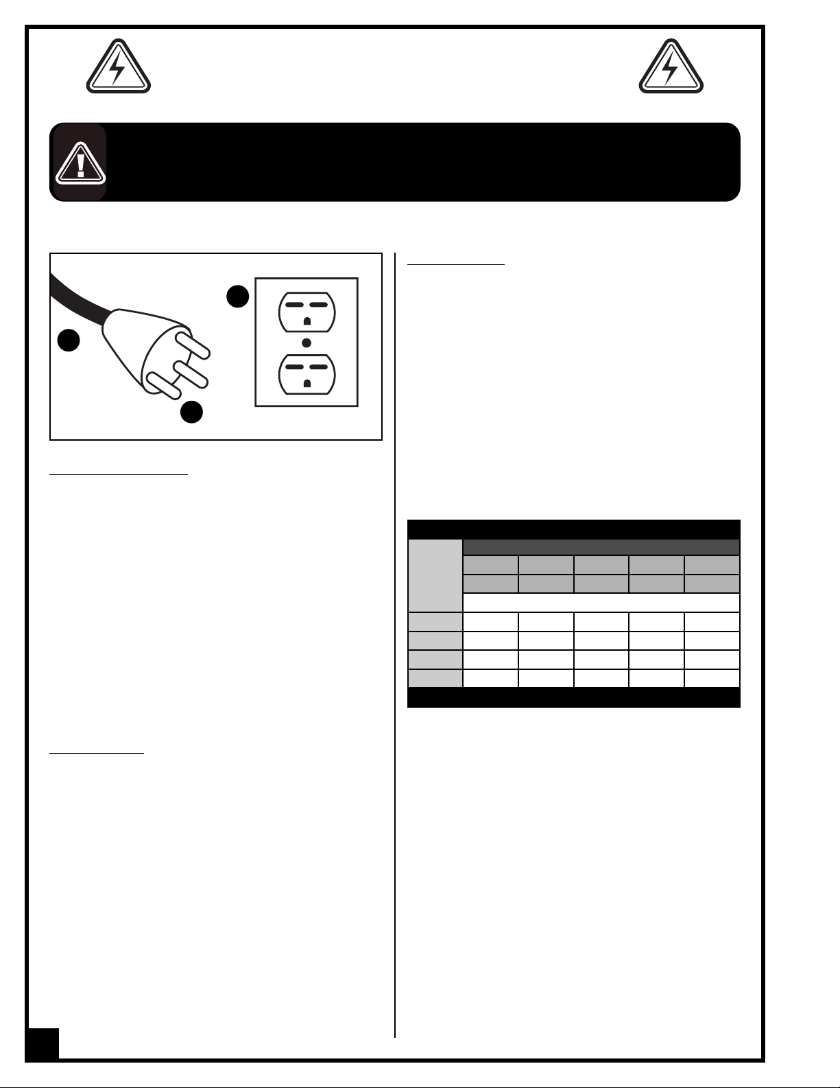
ELECTRICAL REQUIREMENTS
BEFORE CONNECTING THE MACHINE TO THE POWER SOURCE, VERIFY THAT THE VOLTAGE OF YOUR POWER SUPPLY CORRESPONDS
ITH THE VOLTAGE SPECIFIED ON THE MOTOR I.D. NAMEPLATE. A POWER SOURCE WITH GREATER VOLTAGE THAN NEEDED CAN
W
RESULT IN SERIOUS INJURY TO THE USER AS WELL AS DAMAGE TO THE MACHINE. IF IN DOUBT, CONTACT A QUALIFIED ELECTRICIAN
EFORE CONNECTING TO THE POWER SOURCE.
B
THIS TOOL IS FOR INDOOR USE ONLY. DO NOT EXPOSE TO RAIN OR USE IN WET OR DAMP LOCATIONS.
C
A
B
GROUNDING INSTRUCTIONS
In the event of an electrical malfunction or short circuit,
grounding reduces the risk of electric shock to the operator. The motor of this machine is wired for 115 V single
phase operation and is equipped with a 3-conductor
cord A and a 3-prong grounded plug B to fit a matching grounding type receptacle C.
DO NOT MODIFY THE PLUG PROVIDED ! If it will not fit your recepta-
cle, have the proper receptacle installed by a qualified electrician.
CHECK with a qualified electrician or service person if
you do not completely understand these grounding
instructions, or if you are not sure the tool is properly
grounded.
EXTENSION CORDS
If you find it necessary to use an extension cord with your
machine, use only 3-wire extension cords that have 3prong grounding plug and a matching 3-pole receptacle that accepts the tool’s plug. Repair or replace a
damaged extension cord or plug immediately.
Make sure the cord rating is suitable for the amperage
listed on the motor I.D. plate. An undersized cord will
cause a drop in line voltage resulting in loss of power
and overheating. The accompanying chart shows the
correct size extension cord to be used based on cord
length and motor I.D. plate amp rating. If in doubt, use
the next heavier gauge. The smaller the number, the
heavier the gauge.
TABLE - MINIMUM GAUGE FOR CORD
TOTAL LENGTH OF CORD IN FEET
AMPERE
RATING
6 TO 10
10 TO 12
12 TO 16
* NR = Not Recommended
115 VOLTS 25 FEET 50 FEET 100 FEET 150 FEET
230 VOLTS 50 FEET 100 FEET 200 FEET 300 FEET
AWG
< 5
------->
------->
------->
------->
18 16 16 14
18 16 14 12
16 16 14 12
14 12 * NR * NR
CIRCUIT CAPACITY
Make sure that the wires in your circuit are capable of
handling the amperage draw from your machine, as
well as any other machines that could be operating on
the same circuit. If you are unsure, consult a qualified
electrician. If the circuit breaker trips or the fuse blows
regularly, your machine may be operating on a circuit
that is close to its amperage draw capacity. However, if
an unusual amperage draw does not exist and a
power failure still occurs, contact a qualified technician
or our service department.
6
Page 7

4 ½" x 6" METAL CUTTING BANDSAW
90-665 M1
IDENTIFICATION OF MAIN PARTS AND COMPONENTS
D
A
B
G
E
F
H
I
J
C
K
L
A - PILLEY COVER
B - MOTOR
C - BLADE
D - BLADE TENSION KNOB
E - BLADE GUIDE ADJUSTMENT
KNOB
F - VISE
G - VISE ADJUSTMENT
HAND WHEEL
H - SWITCH
I - CARRYING HANDLE
M
J - TOOL TRAY
K - WORK STOP
L - SUPPORT LEG
M - STAND WHEELS
7
Page 8

UNPACKING
Carefully unpack and remove the unit and its components from its shipping container and check for missing or
damaged items as per the list of contents below.
NOTE: Please report any damaged or missing items to
your GENERAL® INTERNATIONAL distributor immediately.
LIST OF CONTENTS QTY
ANDSAW ......................................................................1
B
A -
SUPPORT LEG .................................................................2
B -
TOOL TRAY......................................................................1
C -
PULLEY COVER...............................................................1
D -
VERTICAL TABLE .............................................................1
E -
CARRYING HANDLE.......................................................1
F -
WHEEL.............................................................................1
G -
HARDWARE BAG............................................................1
H -
a - allen key..................................................................1
b - pin ............................................................................2
c - set screw ..................................................................1
d - phillips head screw................................................2
e - hex bolt 5/16” x 3/4” (saw to stand) ....................6
f - hex nut 5/16” (stand) ..............................................6
g - flat washer (tool tray) ............................................6
h - hex bolt M6 x 5/8” (tool tray)................................4
i - flat washer (tool tray)..............................................4
j - nut (tool tray) ...........................................................4
k - hex screw.................................................................2
l - washer.......................................................................4
m - nut ...........................................................................2
WORK STOP....................................................................1
I -
A
D
B
E
F
C
G
H
m
l
a
k
I
b
c
d
g
h
d
i
f
e
PLACEMENT WITHIN THE SHOP / ESTABLISHING A SAFETY ZONE
PLACEMENT WITHIN THE SHOP
This machine should be installed and operated only on a
solid, flat and stable floor that is able to support the weight
of the operator. Using the dimensions shown as a guideline, plan for placement within your shop that will allow
the operator to work unencumbered and unobstructed
by foot traffic (either passing shop visitors or other shop
workers) or other tools or machinery.
ESTABLISHING A SAFETY ZONE
For shops with frequent visitors or multiple operators, it is
advisable to establish a safety zone around shop machinery. A clearly defined “no-go” zone on the floor around
each machine can help avoid accidents that could
cause injury to either the operator or the shop visitor. It is
advisable to take a few moments to either paint (using
non-slip paint) or using tape, define on the floor the limits or perimeter of each machines safety zone. Take steps to
ensure that all operators and shop visitors are aware that these areas are off limits whenever a machine is running
for everyone but the individual operating the unit.
8
18”
42½”
54 ¼”
Page 9

ASSEMBLY INSTRUCTIONS
SERIOUS PERSONAL INJURY COULD OCCUR IF YOU CONNECT THE MACHINE TO THE POWER SOURCE BEFORE YOU HAVE COMPLE-
ED THE INSTALLATION AND ASSEMBLY STEPS. DO NOT CONNECT THE MACHINE TO THE POWER SOURCE UNTIL INSTRUCTED TO DO
T
O.
S
INSTALL THE WHEELS TO STAND
l
k
Unfold the two stand leg assemblies. They are hinged on the edges for easy set up. Use the 1/4” - 2 hex
screw (k), washer (l), and nut (m), to install the wheel
braces in the bottom corners of the leg assemblies.
m
FIX THE SUPPORT LEGS
MOUNT THE CARRYING HANDLE
B
On the other leg, insert the handle into the pre-drilled
holes and secure it with the pins, B.
INSTALL THE TOOL TRAY
With the help of an assistant, lift the bandsaw onto a
pair of closely spaced chair or other support.
Attach the legs to the bandsaw with the 5/16”- 6 hex
screw, flat washers and nuts.
Note: At this time, tighten with a wrench or socket just
enough to secure the parts. Final tightening will take place
when the stand is fully assembled.
FIX THE PULLEY COVER
Place the pulley cover over the motor and the gear
shafts, and secure it with Phillips head screws.
Remove the machine from the chair then install the tool
tray in the middle of the stand with the M6 x 4 hex head
screw, flat washer and nuts.
Check to see if the bandsaw is relatively level, then final
tighten all the nuts
INSTALL THE WORK STOP
Install the work stop shaft into the side of the bandsaw
then lock it in place by tightening the set screw.
9
Page 10

INSTALL THE AUXILIARY TABLE (FOR VERTICAL CUTS)
A
B
o assemble the bandsaw for vertical cutting:
T
. Remove the two flat head screws, A, and the blade
1
guide cover.
. Install the table, B, and replace two screws remo-
2
ved and tighten them.
BASIC ADJUSTMENTS & CONTROLS
TO REDUCE THE RISK OF SHOCK OR FIRE DO NOT OPERATE
THE UNIT WITH A DAMAGED POWER CORD OR PLUG. REPLACE DAMAGED CORD OR PLUG IMMEDIATELY. TO AVOID UN-
XPECTED OR UNINTENTIONAL START-UP, MAKE SURE THAT
E
THE POWER SWITCH IS / BOTH OF THE POWER SWITCHES ARE
N THE OFF POSITION BEFORE CONNECTING TO A POWER
I
SOURCE.
CONNECTING TO A POWER SOURCE
Once the assembly steps have been completed and the
unit is safely secured to a work surface, uncoil the power
cord and plug the power cord into an appropriate outlet.
Refer back to the section entitled “Electrical Requirements”
and make sure all requirements and grounding instructions are followed. When operations have been completed unplug the bandsaw from the power source.
ON/OFF POWER SWITCH
ADJUSTING THE WORK STOP
SWITCH OFF
ON
OFF
The bandsaw is equipped with a simple On/Off power
switch.
To start:
To stop
Pull up the button.
: Push down.
ADJUSTING THE VISE
The vise can hold material up to five inches wide and be
set to cut angles from 0° to 45°.
To adjust the angle on the vise:
1. Loosen the lock nut with a wrench or socket.
2. Use the scale as a guide to set your angle.
3. Tighten the lock nut.
4. Loosen the lock nut on the opposite jaw so the jaw
can flat, and match the angle of the work piece.
5. Tighten the vise against the workpiece.
10
A
B
Slide the work stop, A, onto the end of shaft and lock it
into position with the thumb screw, B.
Page 11

BLADE SPEED
The bandsaw is capable of operating at 80,120, 200 FPM.
The speed can easily be adjusted by changing the V-belt
placement. Shows an illustration of each pulley to belt
combination and the following list provides the blade
peeds in feet per minute.
s
TO CHANGE THE BLADE SPEED
1. Unplug the bandsaw.
2. Unscrew pulley case by using screw driver and open
pulley case.
3. Loosen the motor tension screw, A, to allow the motor
to pivot.
4. Raise the motor to relieve the belt tension and position the belt in the desired pulley alignment.
5. Release the motor and let the motor weight tension
the belt.
6. Tighten the motor tension screw back against the frame of the bandsaw.
7. Close the pulley case and tighten screw.
80 FPM
120 FPM
200 FPM
A
BLADE SELECTION
MATERIAL TPI FPM
Tool steel
Stainless steel
Bearing bronze
Mild steel
Hard brass
Bronze
Soft brass
Aluminum
Other Light metals
When deciding which type of blade to use, consider
the type and thickness of material being cut. Refer to
for recommended blade tooth (TPI) and speed (FPM)
based on the work piece material. The blade must
have at least three teeth in contact with the work piece.
FEED RATE
The feed rate is controlled by the spring and handle.
To adjust the feed rate:
Slower: Twist the handle, A, clockwise to add tension to
the spring.
Faster
: Twist the handle, A, counterclockwise to release
tension from the spring.
24 80
18 120
14 200
ADJUSTING BLADE GUIDES
A
The blade guides should be as close to the work piece
as possible. This will help ensure straight cuts by keeping the blade from twisting and drifting off the cut line.
To adjust the blade guides:
Loosen the knob, A, and slide the blade guide as close
to the work piece as possible, then tighten the knob.
A
11
Page 12

he following tips will help you safely and effectively operate your bandsaw and help you get the maximum cut life
T
of your saw blades.
HORIZONTAL CUTTING
• Use the work stop to quickly and accurately cut multiple pieces of stock to the same length.
Clamp the material firmly in the vise jaws to ensure a
•
straight cut through the material.
• Let the blade reach full speed before touching the
work piece. Never start a cut with the blade in contact with the work piece.
• Chips should be curled and silvery. If the chips are
thin and powder like, increase your feed rate.
If the chips are burned, reduce the blade speed.
•
• Wait until the blade has completely stopped before
removing the workpiece from the vise, and avoid
touching the cut end—it could be very hot!
VERTICAL CUTTING
• Make sure that the vertical table assembly is securely fastened to the bandsaw frame so it will adequately support the work piece.
• Always keep your fingers away from the blade and
always hold the work piece securely against the
table.
• Adjust the blade guides as close as possible to the
work piece to minimize side-to-side blade movement.
CHANGING BLADE
Blades should be changed when they become dull,
damaged, or when you are using materials that require
a blade with a certain type or tooth count.
To change the blade on the bandsaw:
1. Unplug the bandsaw!
2. Raise the head of the bandsaw to the vertical posi-
tion and remove the wheel cover.
3. Loosen the tension knob and slip the blade off of the
wheels.
4. Install the new blade through both blade guide bearings and around the bottom wheel.
5. Hold the blade around the bottom wheel with one
hand and slip it around the top wheel with the other hand, keeping the blade between the blade guide
bearings.
Note: Check to make sure the blade teeth are facing toward the workpiece, after mounting to the bandsaw. Some blades
will have a directional arrow as a guide.
6. When the blade is around both wheels, adjust the position so the back of the blade is against the shoulder of the wheels.
7. Tighten the tension knob in so the blade will not slip on the wheels on start up.
8. Connect the bandsaw to the power source.
9. Briefly turn the bandsaw ON then OFF to position the blade and resume the previous tracking.
If the tracking is fine, proceed to Blade Tension.
12
Page 13

BLADE TENSION
Proper blade tension is essential to long blade life,
straight cuts, and efficient cutting times.
To tension the blade on the bandsaw:
1. Make sure the blade is tracking properly.
2. Unplug the bandsaw!
3. Turn the tension knob, A, in clockwise to tighten the
blade as tight as you can get.
4. Using moderate finger pressure, push against the
side of the blade. The blade should not move more
than 0.004".
5. Another option is to use a blade tensioning gauge, If
you use this gauge please follow the instructions
included with your gauge.
SQUARING THE BLADE
It is always a good idea during the life of your saw to
check and adjust this setting. This adjustment will improve
your cutting results and extend the life of your blade.
To square the blade to the bed of the table:
1. Unplug the bandsaw!
2. Lower the head of the bandsaw all the way until it
contacts the horizontal stop.
3. Place a square, A, on the table bed and against the
edge of the blade, and check different points along
the length of the table between the blade guides.
4. Loosen the hex bolt, B, and rotate the seat until the
blade is vertical to the bed, then tighten the hex bolt.
A
A
B
BLADE GUIDE BEARINGS
The blade guide bearings must be properly adjusted.
One bearing on each assembly has an eccentric bushing that allows the distance between bearings to be
adjusted. The bearings are secured in place by a hex nut
and lock washer.
To adjust the blade guide bearings:
1. Unplug the bandsaw!
2. Position the bandsaw in the vertical position.
3. Loosen the hex nut that secures the bearing to the
eccentric bushing.
4. Using an open-end wrench, adjust the eccentric
bushing position to achieve the desired clearance.
The bearing and blade should have a clearance of 0.001".
5. Tighten the nut to lock the bearing in position.
6. Adjust the other eccentric blade guide bearing in the same manner. The backing bearing should have a gap
between 0.002”-0.003" from the back of the blade.
13
Page 14

OPERATING INSTRUCTIONS
TARTING
S
NEVER USE THE SAW WITHOUT ALL GUARDS AND COVERS IN PLACE.
BE SURE THE BLADE IS NOT IN CONTACT WITH WORKPIECE WHEN THE MACHINE IE STRATED.
1.
The working area should be well lit, clean and free of debris.
. Connect the power cord in the appropriate plug.
2
ote: Refer to “Electrical installations” and be sure all requirements and instructions are followed.
N
3. Raise the bandsaw by its handle and lock it in position.
4. Start the bandsaw.
5. Allow the blade to come to full speed, then begin the cut by letting the head down slowly onto the workpiece.
DO NOT DROP OR FORCE THE HEAD ONTO THE WORKPIECE.
Note: shows correct methods of holding different workpiece shapes.
MAINTENANCE
MAKE SURE THE MACHINE HAS BEEN TURNED OFF AND UNPLUGGED FROM THE POWER SOURCE BEFORE PERFORMING ANY
MAINTENANCE.
For optimum performance from your machine, follow this maintenance schedule and refer to any specific instructions given in this section.
Daily Check: Monthly Check:
• Loose mounting bolts. • V-belt tension, damage, or wear.
• Damaged saw blade. • Lubricate vise screw.
• Worn or damaged wires. • Lubricate gear box.
• Any other unsafe condition.
• Clean after each use.
CLEANING
Cleaning the bandsaw is relatively easy. After using your bandsaw, sweep up and discard any excess chips.
LUBRICATION
Before applying lubricant to any area, wipe the area clean to avoid contamination. Lubricate the vice screws
with general purpose grease.
Remove the cover on the gear and coat the gears with general purpose grease.
14
Page 15

TROUBLE SHOOTING
MACHINE DOES NOT START OR A BREAKER TRIPS.
Possible cause Possible solution
lug / receptacle is at fault or wired incorrectly.
P
Start capacitor is at fault. Test / replace if faulty.
Motor connection wired incorrectly. Correct motor wiring connections.
ower supply is at fault / switched off.
P
On / Off switch is at fault. Replace faulty On button or ON/OFF switch.
Wiring is open / has high resistance.
Motor is at fault. Test / repair / replace.
MACHINE STALLS OR IS UNDERPOWERED
Possible cause Possible solution
Wrong blade for the workpiece material (metal).
Feed rate too fast for task. Decrease fee rate.
V-belt slipping. Replace loose pulley / shaft.
Blade is slipping on wheels. Adjust blade tracking and tension.
Pulley / spocket slipping on shaft. Replace loose pulley / shaft.
Motor bearings are at fault.
Motor is at fault. Test / repair / replace.
est for good contact or correct the wiring.
T
Make sure all hot lines / grounds are operational and
have correct voltage on all legs.
Troubleshoot wires for internal / external breaks; check
for disconnected / corroded connections; repair /
replace wiring.
Use blade with correct properties for your type of
cutting.
Test by rotating shaft; rotational grinding/loose shaft
requires bearing replacement.
MACHINE HAS VIBRATION OR NOISY OPERATION
Possible cause Possible solution
V-belt is slapping belt cover Inspect belt cover for proper installation.
V-belt worn or loose. Inspect / replace belt with a new one.
Pulley is loose.
Realign / replace shaft, pulley, set screw & key as
required.
MACHINE IS LOUD WHEN CUTTING OR BOGS DOWN IN THE CUT
Possible cause Possible solution
Excessive feed rate.
The blade TPI is too great, or the material is too
coarse.
Refer to feed rate, or blade speed and adjust as
required.
Refer to blade selection and adjust as required.
15
Page 16

BLADES BREAK OFTEN
Possible cause Possible solution
The workpiece is loose in vise.
The feed or cut speed is wrong.
The blade TPI is too great, or the material is too
coarse.
The blade is rubbing on the wheel flange. Refer to blade tracking, and adjust as required.
The bandsaw is being started with the blade resting
on the worpiece.
Clamp the workpiece tighter, or use a jig to hold the
workpiece.
Refer to feed rate, or blade speed and adjust as
required.
Refer to blade selection and adjust as required.
Start bandsaw and then slowly lower the headstock
by setting the feed rate.
The guide bearings are misaligned, or the blade is
rubbing on the wheel flange.
The blade is too thick, or the blades are of low quality. Use a higher quality blade.
Refer to blade tracking, or blade guides, and adjust
as required.
BLADES DULLS PREMATURELY
Possible cause Possible solution
The cutting speed is too fast. Refer to blade speed and adjust as required.
The blade TPI is too coarse. Refer to selection and adjust as required.
The blade feed pressure is too light. Refer to feed rate, and adjust as required.
The workpiece has hard spots.
The blade is twisted. Replace the blade.
The blade is slipping on the wheels. Refer to blade tension, and adjust as required.
Increase the feed pressure, and reduce the cutting
speed.
BLADE WEARS ON ONE SIDE
Possible cause Possible solution
The blade guides are worn or misadjusted. Refer to blade guides and replace or adjust.
The blade guide slide bracket is loose. Tighten the blade guide bracket.
The wheels are out of alignment. Refer to blade tracking, adn adjust as required.
TEETH ARE RIPPING FROM THE BLADE
Possible cause Possible solution
The feed pressure is too heavy and the blade speed is
too coarse for the workpiece.
The workpiece is vibrating in the vise.
The blade gullets are loading up with chips. Use a coarser-tooth blade.
Refer to blade selection and decrease the feed
pressure. Refer to feed rate, ad adjust as required.
Re-clamp the workpiece in the vise, and use a jig if
required.
THE CUTS ARE CROOKED
Possible cause Possible solution
The feed pressure is too high. Refer to feed rate, and adjust as required.
The guide bearings are out of adjustment, or too far
away from the worpiece.
The blade tension is low. Refer to blade tension, and adjust as required.
The blade is dull. Refer to blade change and replace the blade.
The blade speed is wrong.
Refer to blade guides and replace or adjust.
Refer to changing blade speed and adjust as
required.
16
Page 17

WIRING DIAGRAM
Switch
115 V
Motor
17
Page 18

18
Page 19

PARTS LIST 90-665 M1
PART N0. DESCRIPTION SPECIFICATION QTY
PART N0. DESCRIPTION SPECIFICATION QTY
90665-01 HEX. HEAD SCREWS 5/16 x 3/4 6
90665-02 HEX. NUTS 5/16 6
90665-03 WASHERS 8.5M/M 12
90665-04 STAND,RIGHT SIDE 1
90665-05 SCREWS 1/4 x 3/8 3
90665-06 PINS 4
90665-07 STAND SHELF 1
90665-08 SCREWS 5/16 x 3/4 1
90665-09 STAND CASTERS ASSEMBLY 1
90665-10 WASHERS 8.5M/M 2
90665-11 HEX. HEAD SCREWS 5/16 x 3/4 2
90665-12 HEX. NUTS 5/16 1
90665-13 STAND,LEFT SIDE 1
90665-14 DRAWING HANDLE, STAND 1
90665-15 ADJUSTING ROD 1
90665-16 ELECTRICAL CABLE/PLUG 1
90665-17 PIVOT ROD 1
90665-18 SUPPORT PLATE 1
90665-19 WORK STOP 1
90665-20 THUMB SCREW 1/4 1
90665-21 WORK STOP ROD 1
90665-22 STRAIN RELIEF 1
90665-23 SWITCH COVER 1
90665-24 BUSHING 1
90665-25 ON/OFF SWITCH 1
90665-25A SWITCH PLATE 1
90665-26 BLADE GUARD 1
90665-27 NUTS 5/16 2
90665-28 HAND WHEEL 1
90665-29 BLADE COVER, L 1
90665-30 BLADE COVER, R 1
90665-31 E-RING 1
90665-32 LEAD SCREWS,VISE 1
90665-33 VISE NUT 1
90665-34 CLAMPING PLATE VISE 1
90665-35 WASHERS 8.5M/M 1
90665-36 HEX. HEAD SCREWS 3/8 x 1" 1
90665-37 CASTING BASE 1
90665-38 NUTS 1/4 4
90665-39 SCALE 1
90665-40 CONDENSER,(MOTOR) 200MFD 1
90665-41 HEX. HEAD SCREWS 5/16 x1 2
90665-43 WASHERS 6M/M 4
90665-44 ELECTRICAL CABLE 1
90665-45 NUT PLATES 1
90665-46 HOOK SCREW M8 x 45 1
90665-47 SPRING 1
90665-48 SCREWS 3/16 x 1/4 4
90665-49 VISE PLATE 1
90665-50 CAP SCREWS 5/16 x 3/4 1
90665-51 SCREWS 5/16 x 3/4 1
90665-52 SCREWS 5/16 x 1 1/4 1
90665-53 SCREWS 5/16 x 1 1/2 1
90665-54 ARM 1
90665-55 AUXILIARY TABLE 1
90665-56 KWOB LOCK, L 5/16 x 1 1/4 1
90665-57 BLADE GUIDE BRACKET , L 1
90665-58 PLUM SCREWS 1/4 x 3/8 3
90665-59 BLADE COVER 1
90665-60 C-RING 8M/M 4
90665-61 BEARING 6000 4
90665-62 GUIDE PIVOT 2
90665-63 BEARING SHAFT PIN 2
90665-64 BLADE SEAT 2
90665-65 BLADE GUIDE BRACKET, R 1
90665-66 BRACKET LOCK, R 5/16 x 1" 2
90665-67 WASHER 10/M/M 2
90665-68 SCREWS 1/4 x 3/8 2
90665-69 BEARING 608 2
90665-70 HEX, NUT 3/8 4
90665-71 DRIVE BLADE WHEEL 1
90665-72 BEARING COVER 2
90665-73 KEY 5 x 18 2
90665-74 SET SCREW 1/4 x 5/16 3
90665-75 HEX. HEAD SCREWS M6 x 12 2
90665-76 SWITCH CUT OFF TIP 1
90665-77 WHEEL 1
90665-78 SCREWS 1/4 x 5/8 4
90665-79 TENSION KNOB 1
90665-80 SCREWS 5/16 x 1" 1
90665-81 BODY FRAME 1
90665-82 CONDENSER COVER 1
90665-83 SCREWS 3/8 x 1 3/8 2
90665-85 MOTOR 1
90665-86 MOTOR PULLEY 1
90665-87 BEARING 6202 4
90665-88 BUSHING 1
90665-89 OIL SEALS 2
90665-90 TRANSMISSION GEAR SHAFT 1
90665-91 TRANSMISSION GEAR 1
90665-92 GASKET, GEAR BOX 1
90665-93 GEAR BOX COVER 1
90665-94 WORM GEAR 1
90665-95 SCREWS M6 x 16 4
90665-96 BUSHING 1
90665-97 SCREWS 5/16 x 3/4 2
90665-98 SCREWS 5/16 x 1" 1
90665-99 NUT 5/16 1
90665-100 NUT 5/16 1
90665-101 GEAR PULLEY 1
90665-102 SCREWS M6 x 16 4
90665-103 BLOCK, BLADE TENSION 1
90665-104 WASHERS 10M/M 1
90665-105 WASHERS 8.5M/M 1
90665-106 SCREWS 3/16 x 1/4 2
90665-107 BLADE WHEEL SHAFT 1
90665-108 C-RING 1
90665-109 BLADE TENSION GUIDES 2
90665-111 PULLEY COVER 1
90665-112 V-BELT(A22) 1
90665-113 SAW BLADE 1640 x 13 x 0.64 1
90665-114 WASHERS 10M/M 1
90665-117 SCREWS 5/16 x 1/2 2
90665-118 SCREWS 1/4 x 3/8 1
90665-120 HANDLE 1
90665-121 SET SCREW 5/16 x 5/16 1
90665-122 SET SCREW 5/16 x 5/16 1
90665-123 GUIDE PIVOTS 2
90665-124 NUT PLATES 1
90665-125 WASHERS 8M/M 1
90665-127 GEAR WASHER 2
90665-128 WIRE CLAMP 1
90665-129 WASHER 1
90665-130 PHILLIPS HEAD SCREW 5/16" x 1-1/4" 1
19
Page 20

MODEL 90-665 M1
8360 Champ-d’Eau, Montreal (Quebec) Canada H1P 1Y3
Tel.: (514) 326-1161
Fax: (514) 326-5565 -
Parts & Service / Fax: (514) 326-5555 - Order Desk
orderdesk@general.ca
www.general.ca
IMPORTANT
When ordering replacement parts, always give the model number, serial number of the machine and
part number. Also a brief description of each item and quantity desired.
 Loading...