

Page 1
SETUP & OPERATION MANUAL
FEATURES
Heavy-duty one-piece frame, designed for
added stability. Requires no further assembly.
Dynamically balanced cast-iron wheels
with replaceable rubber tires,mounted on
heavy-duty bearings.
Solid cast-iron table with heavy-duty onepiece
trunnion and 0-45° right tilting action for bevel
cuts.
Upper and lower dual bakelite block and 5
bearing deluxe blade guide system, with 10
points of contact. (Model 90-290 only)
2 cutting speeds for excellent results in either
hard or soft woods. (Model 90-290 only)
Convenient blade tension adjustment handwheel with tension scale.
Safety foot brake simultaneously slows down
the blade and disconnects electrical circuit for
quick blade stoppage and emergency shutoff.
Powerful, totally enclosed fan cooled (TEFC)
industrial quality motor.
Magnetic safety switch with lock-out switch key
to prevent unauthorized use.
Cast-iron miter gauge and dual miter slots in
table for stable cross cuts on either side of the
blade.
Deluxe Excalibur bandsaw rip fence system
with curved guide block and a 6” wooden
resaw auxiliary fence.
Onboard storage mounts for miter gauge rip
fence.
Short cut-off feed device keeps fingers safely
away from the blade.
* Model 90-290 only. Model 90-380 has 7 bearings.
18”/22” WOOD CUTTING BANDSAW
SPECIFICATIONS
WHEEL SIZE
18” (458 mm) – 90-290
22” (560 mm) – 90-380
WHEEL SPEED
(2) 600/840 rpm – 90-290
(1) 800 rpm – 90-380
MAX/MIN BLADE WIDTH
1 1⁄4” (32 mm)/1⁄4” (6 mm)
BLADE LENGTH
145 5/8” (3700 mm) – 90-290
171 1⁄4” (4350 mm) – 90-380
BLADE SPEED
2820 & 3936 lin. fpm (860/1200 lin. mpm) – 90-290
4590 lin. fpm (1400 lin. mpm) – 90-380
TABLE SIZE/TABLE HEIGHT
24” x 20” (610 x 510 mm)/37 3⁄8” (950 mm) – 90-290
30” X 22 3/4” (765 X 580 mm)/35 1⁄4” (895 mm) – 90-380
TABLE TILT
0°- 45° (Right)
MAX. WIDTH OF CUT/MAX. DEPTH OF CUT
17 5/8” (450 mm)/12” (305 mm) – 90-290
21 5/8” (550 mm)/16” (407 mm) – 90-380
MAXIMUM CUTTING (RIP FENCE)
16” (405 mm) – 90-290
19 5/8” (500 mm) – 90-380
DUST COLLECTION PORTS
2 x 4” (102 mm)
MOTOR
90-290 M1: 3 HP, 220 V 1PH 16 A
90-290 M2: 3 HP, 220 V, 3PH, 8.4 A
90-290 M3: 3 HP, 600 V, 3PH, 3.5 A
90-380 M1: 5 HP, 220 V, 1PH, 26 A
90-380 M2: 7.5 HP, 220/440 V, 3PH, 22/11 A
90-380 M3: 7.5 HP, 600 V, 3PH, 8 A
WEIGHT
605 lbs (275 kg) – 90-290
825 lbs (375 kg) – 90-380
MODEL
90-290
#
#90-380
VERSION 3_REVISION 3 - JUNE 2015 (90-380: 92255913)
© Copyright General® International
Page 2

GENERAL® INTERNATIONAL
8360 Champ-d’Eau, Montreal (Quebec) Canada H1P 1Y3
Telephone (514) 326-1161 • Fax (514) 326-5555 • www.general.ca
THANK YOU for choosing this General
®
International model 90-290/90-380
18”/22” Wood Cutting Bandsaw. This bandsaw has been carefully tested and inspected before
shipment and if properly used and maintained, will provide you with years of reliable service.
For your safety, as well as to ensure optimum performance and trouble-free operation, and
to get the most from your investment, please take the time to read this manual before assembling, installing and operating the unit.
The manual’s purpose is to familiarize you with the safe operation, basic function, and features
of this bandsaw as well as the set-up, maintenance and identification of its parts and components. This manual is not intended as a substitute for formal woodworking instruction, nor
to offer the user instruction in the craft of woodworking. If you are not sure about the safety of
performing a certain operation or procedure, do not proceed until you can confirm, from
knowledgeable and qualified sources, that it is safe to do so.
Once you’ve read through these instructions, keep this manual handy for future reference.
Disclaimer: The information and specifications in this
manual pertain to the unit as it was supplied from the
factory at the time of printing. Because we are committed to making constant improvements, General
International reserves the right to make changes to
components, parts or features of this unit as deemed
necessary, without prior notice and without obligation
to install any such changes on previously delivered
units. Reasonable care is taken at the factory to ensure
that the specifications and information in this manual corres-ponds with that of the unit with which it was
®
supplied. However, special orders and “after factory”
modifications may render some or all information in
this manual inapplicable to your machine. Further, as
several gene-rations of this model of bandsaw and several versions of this manual may be in circulation, if you
own an earlier or later version of this unit, this manual
may not depict your machine exactly. If you have any
doubts or questions contact your retailer or our support
line with the model and serial number of your unit for
clarification.
Page 3

GENERAL® INTERNATIONAL WARRANTY
All component parts of General® International and Excalibur by General International® products
are carefully inspected during all stages of production and each unit is thoroughly inspected upon
completion of assembly.
Limited Lifetime Warranty
Because of our commitment to quality and customer satisfaction, General® International agrees to
repair or replace any part or component which upon examination, proves to be defective in either
workmanship or material to the original purchaser for the life of the tool. However, the Limited Lifetime
Warranty does not cover any product used for professional or commercial production purposes nor for
industrial or educational applications. Such cases are covered by our Standard 2-year Limited Warranty
only. The Limited Lifetime Warranty is also subject to the “Conditions and Exceptions” as listed below.
Standard 2-Year Limited Warranty
All products not covered by our lifetime warranty including products used in commercial, industrial and
educational applications are warranted for a period of 2 years (24 months) from the date of purchase.
General® International agrees to repair or replace any part or component which upon examination,
proves to be defective in either workmanship or material to the original purchaser during this 2-year
warranty period, subject to the “conditions and exceptions” as listed below.
To file a Claim
To file a claim under our Standard 2-year Limited Warranty or under our Limited Lifetime Warranty,
all defective parts, components or machinery must be returned freight or postage prepaid to
General® International, or to a nearby distributor, repair center or other location designated by
General® International. For further details call our service department at 1-888-949-1161 or your local
distributor for assistance when filing your claim.
Along with the return of the product being claimed for warranty, a copy of the original proof of purchase
and a “letter of claim” must be included (a warranty claim form can also be used and can be obtained,
upon request, from General® International or an authorized distributor) clearly stating the model and
serial number of the unit (if applicable) and including an explanation of the complaint or presumed
defect in material or workmanship.
CONDITIONS AND EXCEPTIONS:
This coverage is extended to the original purchaser only. Prior warranty registration is not required but
documented proof of purchase i.e. a copy of original sales invoice or receipt showing the date and location of the purchase as well as the purchase price paid, must be provided at the time of claim.
Warranty does not include failures, breakage or defects deemed after inspection by
General®International to have been directly or indirectly caused by or resulting from; improper use, or
lack of or improper maintenance, misuse or abuse, negligence, accidents, damage in handling or transport, or normal wear and tear of any generally considered consumable parts or components.
Repairs made without the written consent of General® International will void all warranty.
Page 4

TABLE OF CONTENTS
Rules for safe operation .............................. 5
Electrical requirements .............................. 6
Electrical Connections .............................................. 6
Grounding instructions .............................................. 6
Circuit capacity ......................................................... 6
Extension cords .......................................................... 6
Identification of main parts and
components ........................................................................7
Unpacking ................................................ 8
List of contents ............................................................ 8
Additional requirements for set up .......................... 8
Clean up..................................................... 8
Basic functions of the unit .......................... 9
Lifting and handling the machine ................ 9
Placement within the shop / Establishing a
safety zone ......................................................................10
Placement within the shop ................................... 10
Establishing a safety zone ..................................... 10
Blade Clearance ..................................................... 14
Adjusting blade tension .......................................... 16
Adjusting blade tracking ........................................ 17
Adjusting the upper/lower blade guides
and thrust bearig .......................................28
Positioning the upper and lower blade guide/
thrust bearing assemblies ....................................... 18
Positioning the upper/lower blade guides .......... 19
Positioning the upper/lower thrust bearing ......... 19
Adjusting the blade guard for depth of cut ........ 20
Changing spped settings (model 90-290 only) ...... 20
Positioning the upper/lower blade guides .......... 19
Align the laser line marker to the blade .............. 21
Operating Instructions ...............................21
Connecting to dust collector ................................. 21
Checklist before starting .......................................... 21
Operations step-by-step .......................................... 22
To stop the machine ............................................... 22
Using the rip fence ................................................... 22
Using the miter gauge ............................................ 22
Using the push handle ............................................ 23
Assembly instructions ...............................10
Attach the storage brackets................................... 10
Install the foot brake ............................................... 10
Install the blade tension adjustment
handwheel handle .................................................. 11
Install the push handle ............................................ 11
Install the fence assembly ...................................... 11
Basic Adjustments & Controls .....................11
Magnetic safety switch ........................................... 11
Safety lock-out switch .............................................. 12
Foot brake ................................................................ 12
Connecting to a power source ............................. 12
Tilting the table ......................................................... 12
Adjusting the 90º table stop and re-aligning
the angle pointer ....................................................... 13
Blade Selection ........................................................ 14
Removing/Installing the blade .............................. 14
Cutting curves .......................................................... 23
Cutting circles .......................................................... 23
Periodic Maintenance & Lubrication ............23
Periodic maintenance ............................................ 23
Lubrication ............................................................................ 24
Required Maintenance ...............................24
Replacing the bandsaw blade ............................. 24
Replacing the upper and lower blade guides
and thrust bearings ................................................. 25
Replacing the wheel tire ......................................... 26
Replacing the lower wheel brush ......................... 26
Replacing the lower wheel motor belt ................. 26
Recommended optional accessories ..........27
Parts list & diagrams .................................28
Page 5

Rules for Safe Operation
To help ensure safe operation, please take a moment to learn the machine’s applications and limitations, as well as potential hazards. General® International disclaims any real or implied warranty and
hold itself harmless for any injury that may result from the improper use of it’s equipment.
1. Do not operate the bandsaw when tired, distracted
or under the effects of drugs, alcohol or any medi cation that impairs reflexes or alertness.
2. The working area should be well lit, clean and free
of debris.
3. Keep children and visitors at a safe distance when
the bandsaw is in operation; do not permit them to
operate the bandsaw.
4. Childproof and tamper proof your shop and all
machinery with locks, master electrical switches
and switch keys, to prevent unauthorized or unsu pervised use.
5. Stay alert! Give your work your undivided attention.
Even a momentary distraction can lead to serious
injury.
6. Fine particulate dust is a carcinogen that can be
hazardous to health. Work in a well-ventilated area
and whenever possible use a dust collector. Wear
face, eye, ear, respiratory and body protection de vices.
7. Do not wear loose clothing, gloves, bracelets,
necklaces or other jewelry while the bandsaw is in
operation.
8. Be sure that adjusting wrenches, tools, drinks and
other clutter are removed from the machine and/or
the table surface before operating.
9. Keep hands well away from the blade and all mov
ing parts. Use a brush, not hands, to clear away
chips and dust.
10. Adjust and position upper and lower blade guides
before starting to cut. Upper blade guide should be
adjusted to approximately 1/8” above the material
to be cut.
11. Adjust blade tension and tracking before starting to
cut.
12. Saw teeth must point down toward the table.
15. Use suitable workpiece support if the workpiece
does not have a flat surface.
16. Hold material firmly against the table.
17. Do not work on long stock without adequate sup-
port on the out feed end of the table.
18. If using a power feeder, stop the feeder before stop ping the bandsaw.
19. Do not push or force stock into the blade. The
bandsaw will perform better and more safely when
working at the rate for which it was designed.
20. Avoid working from awkward or off balance posi tions. Do not overreach and keep both feet on
floor.
21. Keep guards in place and in working order. If a
guard must be removed for maintenance or clea ning be sure it is properly re-attached before using
the tool again.
22. Never leave the machine unattended while it is run ning or with the power on.
23. Use of parts and accessories NOT recommended
by
ment malfunction or risk of injury.
24. Never stand on machinery. Serious injury could re sult if the tool is tipped over or if the cutting tool is
unintentionally contacted.
25. Always disconnect the machine from the power
source before servicing or changing accessories
such as blades, or before performing any mainte nance or cleaning, or if the machine will be left
unattended.
26. Make sure that the switch is in the “OFF” position
before plugging in the power cord.
27. Make sure the tool is properly grounded. If equip ped with a 3-prong plug it should be used with a
three-pole receptacle. Never remove the third prong.
General® International may result in equip-
13. Be sure that the blade has gained full operating
speed before starting to cut.
14. Always use a clean, properly sharpened blade.
Dirty or dull blades are unsafe and can lead to
accidents.
28. Do not use this bandsaw for other than its intended
use. If used for other purposes,
General® International disclaims any real or
implied warranty and holds itself harmless for any
injury, which may result from that use.
5
Page 6
ELECTRICAL REQUIREMENTS
BEFORE CONNECTING THE MACHINE TO THE POWER SOURCE, VERIFY THAT THE VOLTAGE OF YOUR POWER SUPPLY CORRESPONDS WITH THE VOLTAGE SPECIFIED ON THE MOTOR I.D. NAMEPLATE. A POWER SOURCE WITH GREATER VOLTAGE THAN NEEDED CAN RESULT IN SERIOUS INJURY TO THE USER AS WELL AS DAMAGE TO THE MACHINE. IF IN DOUBT, CONTACT A QUALIFIED
ELECTRICIAN BEFORE CONNECTING TO THE POWER SOURCE.
THIS TOOL IS FOR INDOOR USE ONLY. DO NOT EXPOSE TO RAIN OR USE IN WET OR DAMP LOCATIONS.
NOTE: VOLTAGE REQUIREMENTS AND AMPERAGE DRAW FOR M2 & M3 3-PHASE MOTORS MAY NOT BE FULLY
DESCRIBED IN THIS MANUAL. FOR COMPLETE ELECTRICAL REQUIREMENTS REFER TO THE MOTOR I.D. NAME PLATE ON
THE MACHINE. IF IN DOUBT CONSULT A LICENSED QUALIFIED ELECTRICIAN BEFORE PROCEEDING.
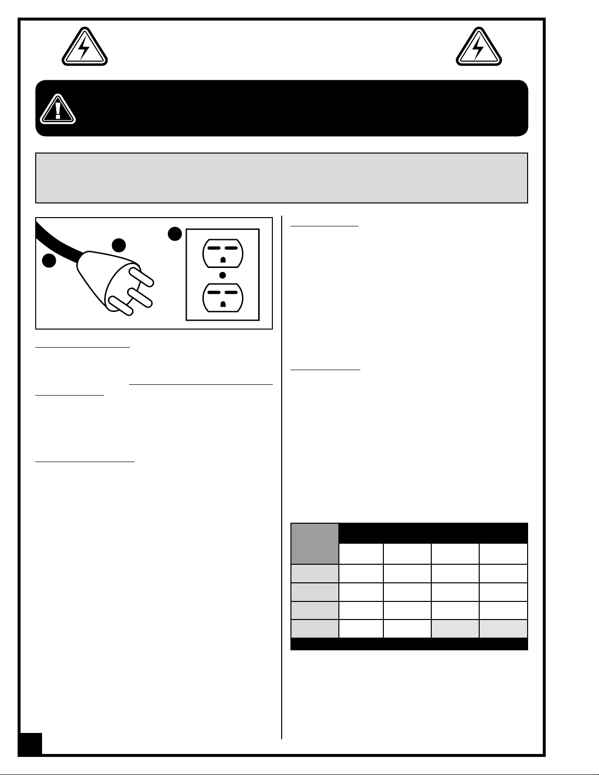
C
B
A
ELECTRICAL CONNECTIONS
Both a manual circuit breaker (or similar device) as
well as an electrical plug (similar to the one shown) are
re-commended and should be installed by a quali-
fied electrician.
Use locally approved wire A that includes a separate
grounding wire and a 3 prong grounding type plug B
with a matching receptacle C.
GROUNDING INSTRUCTIONS
In the event of an electrical malfunction or short circuit,
grounding reduces the risk of electric shock to the
operator. The motor of the “M1” model of this machine
is wired for 220V single phase operation.
As with many stationary industrial type machines,
be-cause each installation situation is unique, this
bandsaw is supplied without a power cord or plug.
The installation of an appropriate power cord and
plug must be performed by a qualified electrician. The
ma-chine must be connected to an electrical source
using a power cord that has a grounding wire, which
must also be properly connected to the grounding
prong on the plug. The outlet must be properly installed
and grounded and all electrical connections must be
made in accordance with all local codes and regulations.
CIRCUIT CAPACITY
Make sure that the wires in your circuit are capable of
handling the amperage draw from your machine, as
well as any other machines that could be operating on
the same circuit. If you are unsure, consult a qualified
electrician. If the circuit breaker trips or the fuse blows
regularly, your machine may be operating on a circuit
that is close to its amperage draw capacity. However,
if an unusual amperage draw does not exist and a
power failure still occurs, contact a qualified technician
or our service department.
EXTENSION CORDS
The use of an extension cord is not generally recommended for 220V equipment. If you find it necessary,
use only 3-wire extension cords that have 3-prong
grounding plug and a matching 3-pole receptacle that
accepts the tool’s plug. Repair or replace a damaged
extension cord or plug immediately.
Make sure the cord rating is suitable for the amperage
listed on the motor I.D. plate. An undersized cord will
cause a drop in line voltage resulting in loss of power
and overheating. The accompanying chart shows the
correct size extension cord to be used based on cord
length and motor I.D. plate amp rating. If in doubt, use
the next heavier gauge. The smaller the number, the
heavier the gauge.
AMPERES
(AMPS)
< 5
EXTENSION CORD LENGTH
50 FEET 100 FEET 200 FEET 300 FEET
18 16 16 14
6 TO 10 18 16 14 12
10 TO 12 16 16 14 12
12 TO 16 14 12
* NR = Not Recommended
* NR * NR
6
Page 7
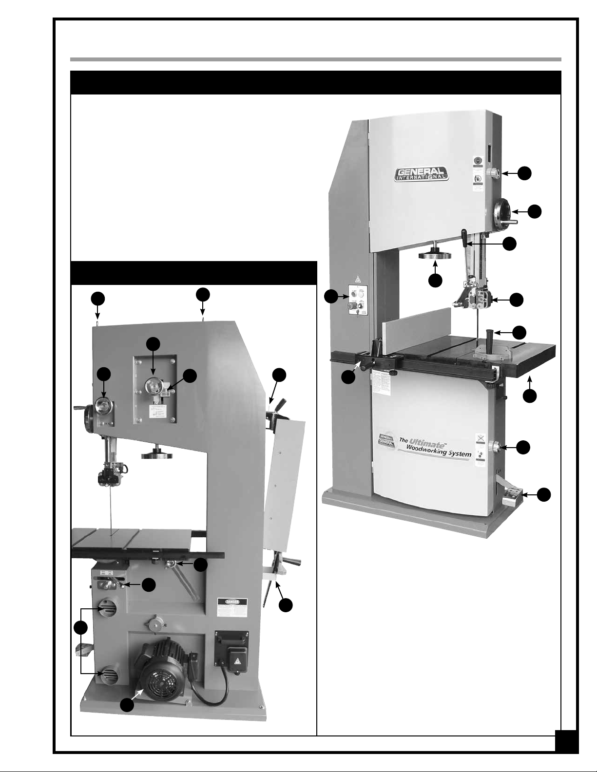
IDENTIFICATION OF MAIN PARTS AND COMPONENTS
FRONT VIEW
A- UPPER WHEEL COVER DOOR LOCK KNOB
B- BLADE GUARD HEIGHT ADJUSTMENT HANDWHEEL
C- PUSH HANDLE
D- BLADE TENSION ADJUSTMENT HANDWHEEL
E- MAGNETIC SAFETY SWITCH
F- UPPER BLADE GUIDE SYSTEM
G- MITER GAUGE
H- RIP FENCE
I- TABLE
J- LOWER WHEEL COVER DOOR LOCK KNOB
K- FOOT BRAKE
A
B
C
REAR VIEW
L
M
O
S
T
L
N
R
P
Q
E
H
L- LIFTING EYEBOLTS (MODEL 90-380 ONLY)
M- BLADE TRACKING ADJUSTMENT HANDWHEEL
N- BLADE TENSION SCALE
O- BLADE GUARD HEIGHT LOCKING HANDWHEEL
P- RIP FENCE STORAGE BRACKET
Q- MITER GAUGE STORAGE BRACKET
R- TABLE TILT LOCK KNOB
S- TABLE TILT LOCKING LEVER
T- DUST OUTLETS
U- MOTOR
D
F
G
I
J
K
U
7
Page 8
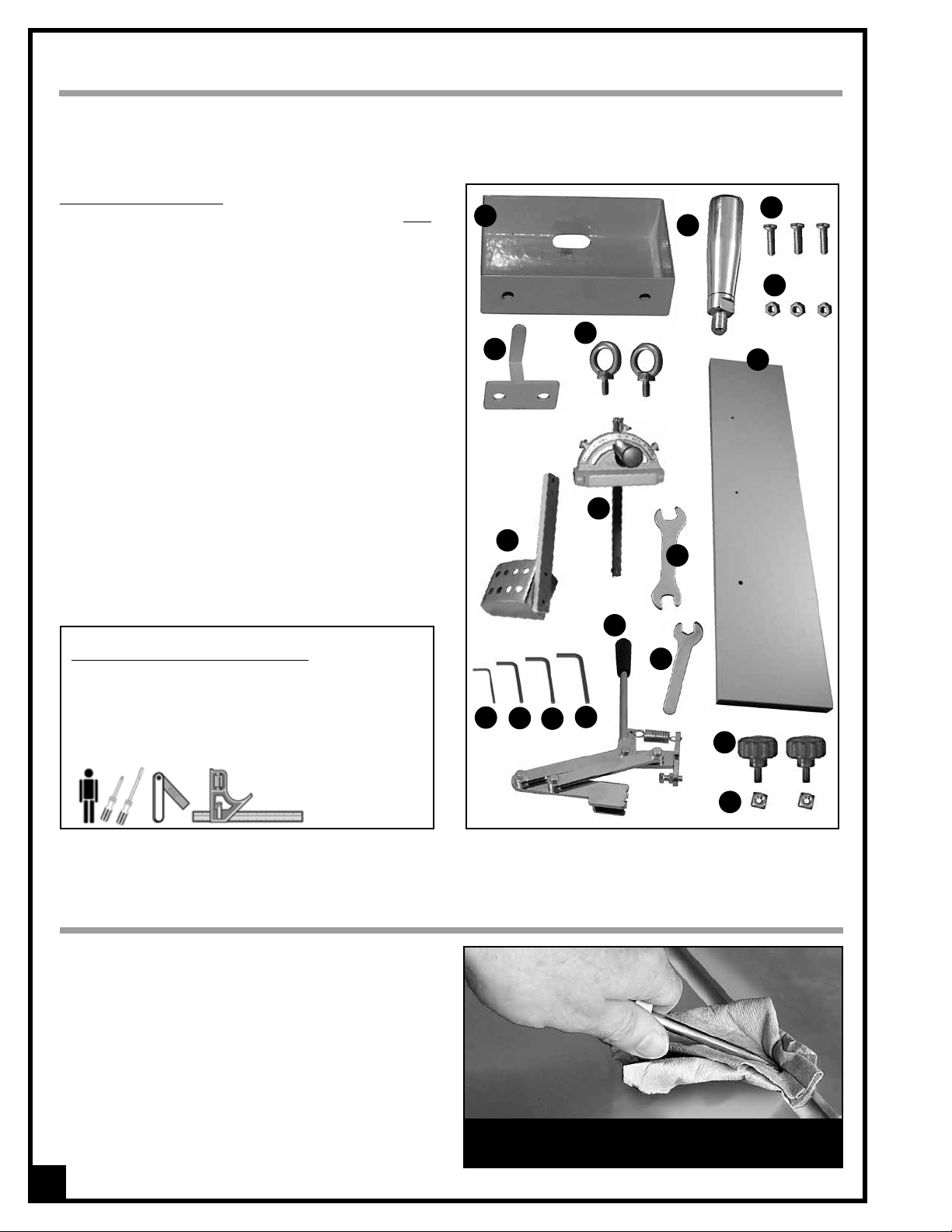
UNPACKING
Carefully unpack and remove the unit and its components from its shipping container and check for missing or
damaged items as per the list of contents below.
NOTE: Please report any damaged or missing items to your GENERAL® INTERNATIONAL distributor immediately.
LIST OF CONTENTS
QTY
A- BANDSAW (NOT SHOWN) ........................................... 1
B- MITER GAUGE STORAGE BRACKET ............................. 1
C- HANDWHEEL HANDLE* ................................................ 1
D- WOOD SCREW* ........................................................... 3
E- HEX NUT* ...................................................................... 3
F- RIP FENCE STORAGE BRACKET .................................... 1
G- EYEBOLT* (
H- WOODEN AUXILIARY FENCE* ..................................... 1
I- FOOT BRAKE (
J- MITER GAUGE .............................................................. 1
K- 12-14 MM OPEN END WRENCH* ................................ 1
L- 3 MM ALLEN KEY* ....................................................... 1
M- 4 MM ALLEN KEY* ....................................................... 1
N- 6 MM ALLEN KEY* ....................................................... 1
O- 8 MM ALLEN KEY* (
P- PUSH HANDLE ............................................................... 1
Q- 10 MM OPEN END WRENCH* .................................... 1
R- FRONT FENCE LOCK KNOB * ...................................... 2
S- SQUARE NUT* ............................................................... 2
Note: Deluxe Excalibur Universal Bandsaw Rip Fence System
is packaged separately. Refer to the manual supplied in the
box with the Excalibur Rip Fence for complete list of contents.
*Packaged in the box with the Excalibur Rip Fence System.
Model 90-380 only) ..................................... 2
Model 90-290 only) ................................ 1
Model 90-290 only) .......................... 1
*
B
G
F
I
*
J
P
*
C
*
K
D
*
E
*
H
ADDITIONAL REQUIREMENTS FOR SET UP
• Extra person for help with lifting
• Phillips screwdriver
• Flat head screwdriver
• Feeler gauge set
• Combination square
CLEAN UP
The protective coating on the saw table prevents rust from
forming during shipping and storage. Remove it by rubbing with a rag dipped in kerosene, mineral sprits or paint
thinner. (Dispose of potentially flammable solvent-soaked
rags according to manufacturer’s safety recommendations.)
A putty knife, held flat to avoid scratching the surface, may
also be used to scrape off the coating followed by cleanup with solvent. Avoid rubbing the saw’s painted surfaces,
as many solvent-based products will remove paint.
To prevent rust, apply a light coating of paste wax or
use regular applications of any after-market surface protectant or rust inhibitor.
*
Q
L
Tip: With a screw driver, push a solvent-saturated rag into
the T-slots to remove the grease so the miter gauge will
slide freely.
*
*
M
O
*
*
N
*
R
*
S
8
Page 9
BASIC FUNCTIONS OF THE UNIT
Both the 90-290 18” and 90-380 22” Wood Cutting Bandsaw are designed to accommodate blade widths from
1/4” to 1-1/4”. The 18” model 90-290 is supplied with a
3/4” wide general purpose blade and the 22” model
90-380 with a 1” wide general purpose blade.
Note: Generally speaking, because the upper wheel height is
somewhat adjustable (to allow for blade tensioning), a blade
length variation of plus or minus 1/2” from the “ideal blade
length” can be accommodated.
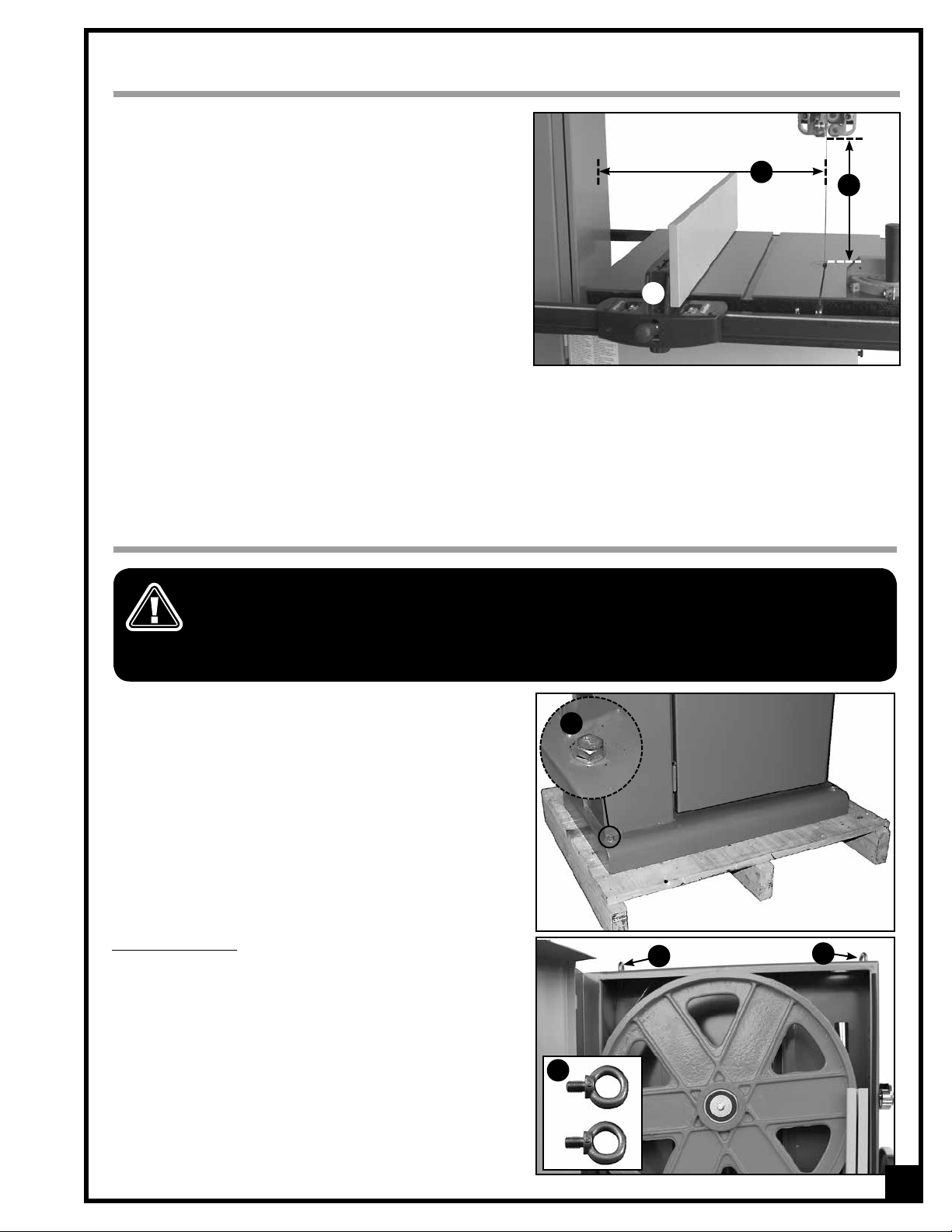
The Maximum inboard width of cut (space between the
blade and the body of the saw A) is 17 5/8” for the 90-290
and 21 5/8” for the 90-380.
For cutting thicker stock or for resawing, the maximum
depth of cut B (or max. workpiece height) is 12” for the
90-290 and 16” for the 90-380.
An adjustable rip fence C is supplied to serve as a straightedge to guide the workpiece for longer rip cuts and
includes an auxiliary fence face for additional fence height to support taller stock for resawing. The fence can
easily be removed and set aside when not required, for example when making curved cuts.
C
A
B
LIFTING AND HANDLING THE MACHINE
THIS BANDSAW IS VERY HEAVY. DO NOT OVER-EXERT. A HOIST OR FORKLIFT WITH CHAINS WILL BE NEEDED
FOR THE FOLLOWING STEP.
TO LIMIT THE RISK OF SERIOUS INJURY OR DAMAGE TO THE MACHINE, ANY EQUIPMENT USED TO LIFT OR MOVE
THIS MACHINE (HOIST OR FORKLIFT) SHOULD HAVE A RATED CAPACITY IN EXCESS OF 605 LBS (275 KG) FOR
MODEL 90-290 AND 825 LBS (375 KG) FOR MODEL 90-380.
To limit the potential for damage in transport, this bandsaw
is shipped from the factory bolted to its crate.
With a forklift or hydraulic pallet jack, move the entire crate
as close to the final installation location as possible, and
then uncrate the saw and remove the screws A that secure
it to the crate.
Model 90-380 only
Two hoisting eyebolts B are supplied for installation on top
of the saw C to facilitate lifting and setting the saw down.
Make sure to use an appropriate capacity hoist or forklift
with chains properly secured to the hoisting eyebolts and
lift the saw from the crate and carefully set it down in the
desired location.
A
C
B
C
9
Page 10
PLACEMENT WITHIN THE SHOP / ESTABLISHING A SAFETY ZONE
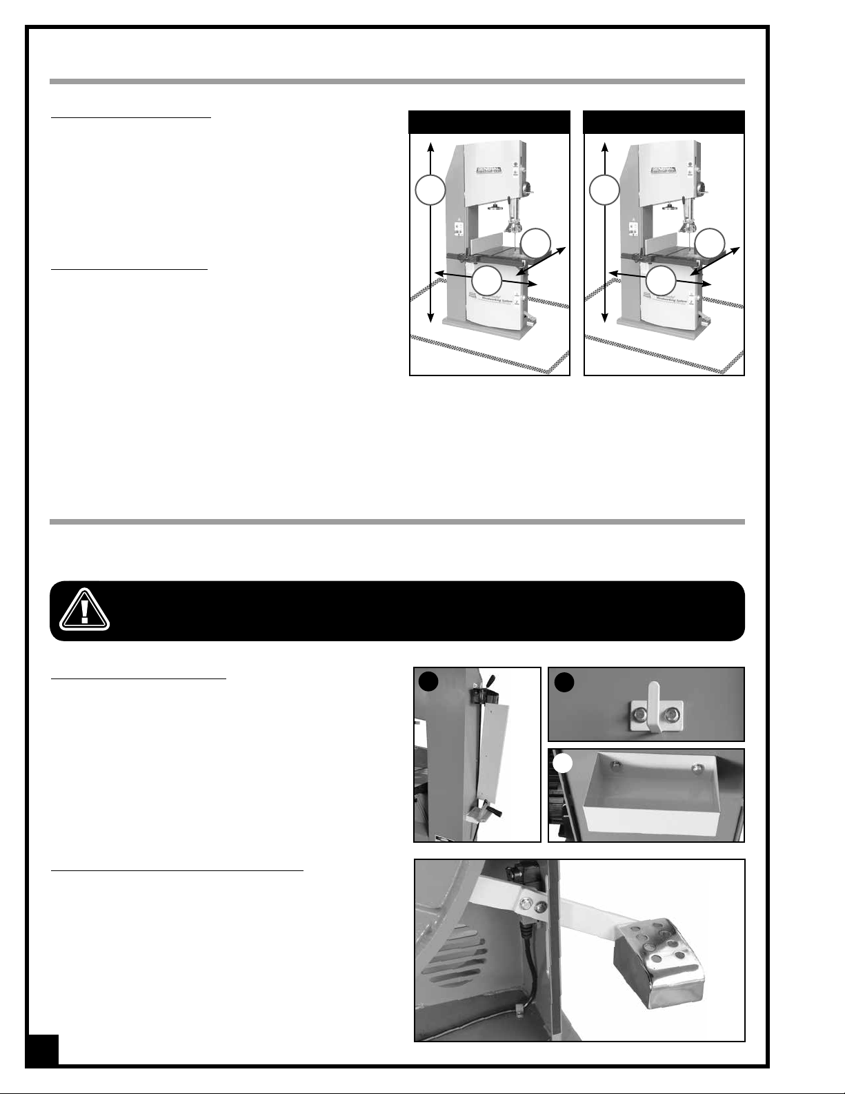
PLACEMENT WITHIN THE SHOP
80
5/8”
Model 90-380Model 90-290
3/4”
37
This machine should be installed and operated only
on a solid, flat and stable floor that is able to support
the weight of the bandsaw and the operator. Using the
di-mensions shown as a guideline, plan for placement
within your shop that will allow the operator to work
unencumbered and unobstructed by foot traffic (either
passing shop visitors or other shop workers) or other tools
or machinery.
74
3/8”
35
7/8”
ESTABLISHING A SAFETY ZONE
”
For shops with frequent visitors or multiple operators, it is
advisable to establish a Safety Zone around shop machinery. A clearly defined “no-go” zone on the floor around
each machine can help avoid accidents that could
cause injury to either the operator or the shop visitor. It is
advisable to take a few moments to either paint (using
non-slip paint) or using tape, define on the floor the limits
or perimeter of each machines safety zone. Take steps to
ensure that all operators and shop visitors are aware that these areas are off limits whenever a machine is running
for everyone but the individual operating the unit.
39
45
7/8”
ASSEMBLY INSTRUCTIONS
For your convenience this bandsaw is shipped from the factory partially assembled and requires only minimal
assembly and set up before being put into service.
SERIOUS PERSONAL INJURY COULD OCCUR IF YOU CONNECT THE SAW TO THE POWER SOURCE BEFORE YOU HAVE
COMPLETED THE INSTALLATION AND ASSEMBLY STEPS.
DO NOT CONNECT THE SAW TO THE POWER SOURCE UNTIL INSTRUCTED TO DO SO.
ATTACH THE STORAGE BRACKETS
This bandsaw is supplied with convenient onboard storage brackets to safely stow the rip fence and miter
gauge out of the way when not in use, A.
Attach the rip fence storage bracket B and miter
gauge storage brackets C to the left side of the saw as
shown, using the bolts and washers already mounted
to the saw.
A
B
C
INSTALL THE FOOT BRAKE (MODEL 90-290 ONLY)
1. Open the lower wheel cover door.
2. Attach the foot brake to the foot brake mounting bar
as shown using the two 3/8” cap screws, lock washers
and flat washers already installed on the mounting
bar.
3. Firmly tighten with the supplied 8 mm wrench.
10
Page 11
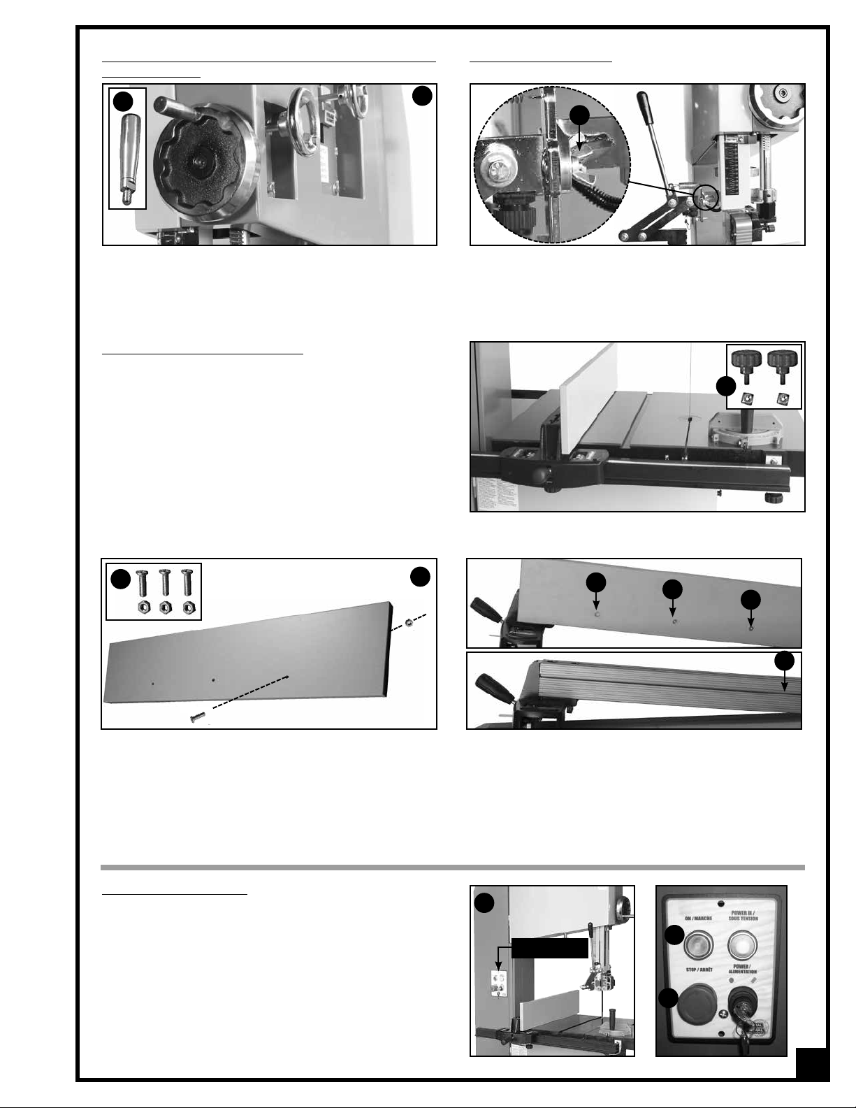
INSTALL THE HANDLE ON THE BLADE GUARD HEIGHT ADJUSTMENT HANDWHEEL
A
B
INSTALL THE PUSH HANDLE
A
1. Thread the handle A on the blade guard adjust ment handwheel as shown in B.
2. Firmly tighten the handle using the supplied 12 mm
wrench.
3. Attach the push handle to the push handle bracket
as shown using the two wing nuts A already
mount- ed on the push handle bracket.
INSTALL THE EXALIBUR FENCE SYSTEM
This bandsaw is supplied with an Excalibur Deluxe Bandsaw
Rip Fence System.
Follow all assembly and adjustment instructions in the 90-075A
manual supplied in the box with the Rip Fence System.
For added convenience, two lock knobs with square nuts
A are supplied with this bandsaw in replacement of the
5/16” screws, flat washers and square nuts supplied with
the fence system for front rail installation.
An auxiliary wooden fence is also supplied for enhanced workpiece support when working with taller stock. Install
the auxiliary wooden fence as follows:
A
B
C
C
A
C
D
Loosely attach the 3 supplied screws and nuts A to the wooden fence as shown in B. Install the wooden fence on
the right face of the rip fence by sliding the nut of the 3 screw/nut assemblies C in the T-slot on the right face of the
rip fence D. Using a screwdriver, tighten the screws to secure the wooden fence against the rip fence.
BASIC ADJUSTMENTS AND CONTROLS
MAGNETIC SAFETY SWITCH
This bandsaw is equipped with a magnetic safety switch
located on the control panel A at the front of the machine. This magnetic switch is designed to protect the unit
and the user from power surges, power outages and
un-wanted or unintentional start-up.
The switch assembly is equipped with a green “ON” button B and a RED spring loaded “STOP” button C. Once
the RED “STOP” button has been pressed, the machine
can only be started by turning the RED button to the
right to release the stop button.
A
B
CONTROL PANEL
C
11
Page 12
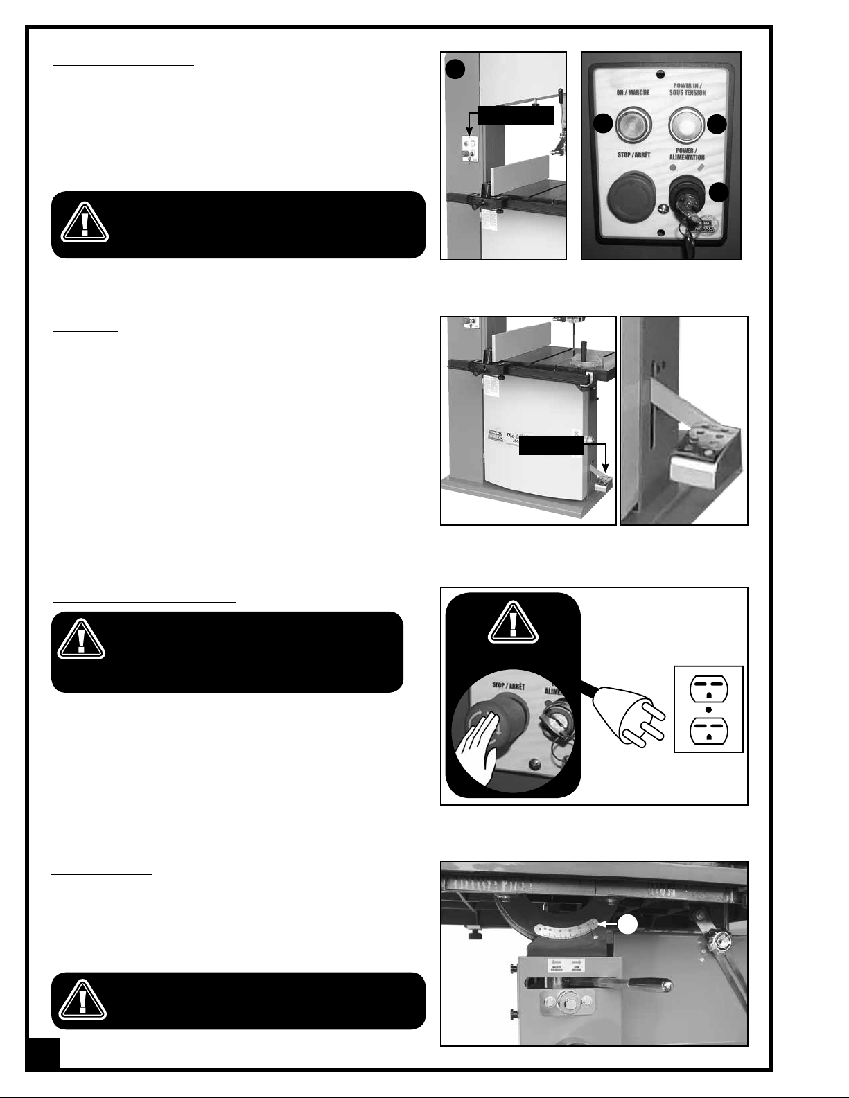
SAFETY LOCK-OUT SWITCH
To prevent unauthorized use, this bandsaw is also equipped
with a safety lock-out switch with removable key, D, located at
the front of the machine, on the control panel, A.
When this switch is locked, the machine cannot be started by
pressing on the green “on” button B. To start the saw, set the
power lock-out switch to the “on” position; the “power in” indicator light E will illuminate.
SET THE LOCK-OUT SWITCH TO THE OFF POSITION
AND STORE THE KEYS IN A SAFE PLACE, OUT OF THE
REACH OF CHILDREN, WHENEVER THE BANDSAW IS
NOT IN USE.
FOOT BRAKE
For quick blade stoppage and emergency shut-off, this bandsaw is equipped with a foot brake located at the bottom
right of the machine. This safety foot brake simultaneously
slows down the blade and disconnects electrical circuit to
the motor.
Notice – The foot brake is not designed to function as the primary
stop mechanism of this saw.
The foot brake should be used for emergency situations or any
time it is necessary to immobilize the blade quicker than normal.
Under normal working conditions the red stop button should be
used as the primary stop mechanism. Continuously using the foot
brake as the primary stop mechanism will lead to premature wear
of the brake.
A
CONTROL PANEL
FOOT BRAKE
B
E
D
CONNECTING TO A POWER SOURCE
TO REDUCE THE RISK OF SHOCK OR FIRE DO NOT OPERATE THE UNIT WITH A DAMAGED POWER CORD OR PLUG.
REPLACE DAMAGED CORD OR PLUG IMMEDIATELY.
TO AVOID UNEXPECTED OR UNINTENTIONAL START-UP,
MAKE SURE THAT THE POWER SWITCH IS IN THE OFF
POSITION BEFORE CONNECTING TO A POWER SOURCE.
Refer back to section “Electrical Requirements” and make
sure all requirements and grounding instructions are followed.
Once the assembly has been completed, plug the power
cord into an appropriate outlet.
When you have finished using the machine be sure to unplug
the bandsaw from the power source.
TILTING THE TABLE
The table can be tilted to any angle from 0° to 45° to the right
to allow for any type of bevel (or angle) cutting.
Refer to the table tilt angle indicator A located under the
bandsaw table, to set the angle of the table to the desired
position.
BEFORE MAKING ANY ADJUSTMENTS, MAKE SURE THAT
THE SWITCH IS IN THE “OFF” POSITION AND THAT THE
POWER CORD IS UNPLUGGED.
SWITCH OFF
A
12
Page 13
1. Push the table locking lever B to the left to unlock the
table.
2. Loosen the table lock knob C and tilt the table until
it is at the desired angle. (Refer to the angle indica tor A.)
A
C
3. Re-tighten lock knob C and push locking lever B to
the right to lock the table in position.
B
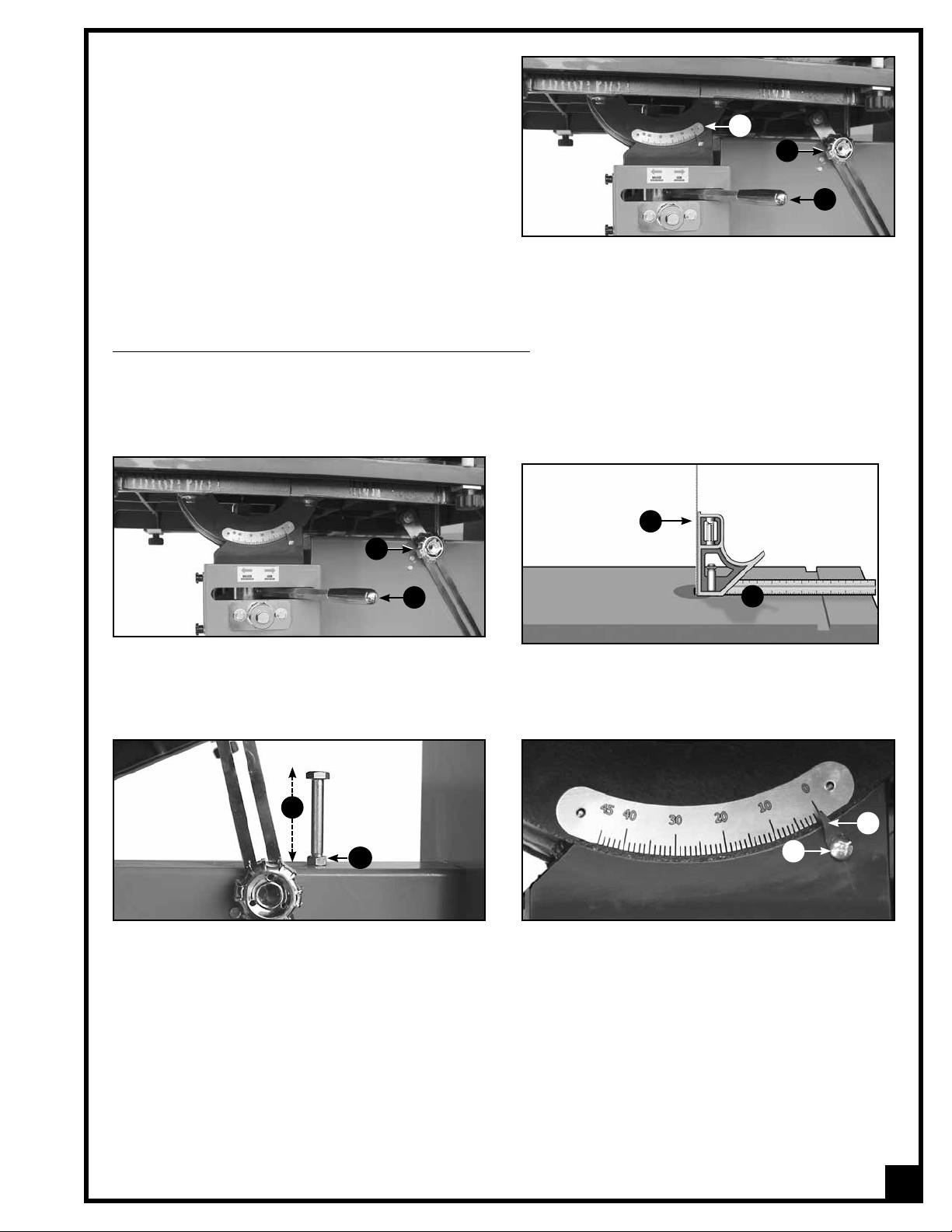
ADJUSTING THE 90º TABLE STOP AND RE-ALIGNING THE ANGLE POINTER
To ensure that your 90º cuts are square and that angled cuts are accurate with the angle indicator scale, the table
default position must be set to 90º to the blade and the angle indicator pointer must be set to read 0 when the table
is in the default (90º ) position.
To set the table-stop bolt:
D
B
A
C
1. Loosen table locking lever A and table lock knob B.
2. Place a combination square C flat on the table with the heel of the square flat against the saw blade D.
3. Level the table until it is exactly 90° to the blade, then tighten locking lever A and lock knob B.
F
E
4. Using a 19 mm open end wrench, loosen the jam
nut E on the 90º table-stop bolt, then adjust the
height of the bolt F until it touches the underside of
the table.
5. Loosen table locking lever A and table lock knob
B and make sure the table is resting on the table-
stop bolt.
6. Check the square and make sure the table is still at
8. With the table set to 90º and the stop bolt at the
correct height, make sure the table tilt angle indi cator pointer is set to read 0º.
9. If the pointer needs to be adjusted, loosen the
screw G on the pointer of the front trunnion and
adjust the pointer H to the 0 point on the scale.
Then re-tighten the screw to secure the pointer in
place.
G
90° to the blade. If not, re-adjust the table-stop bolt.
7. Re-tighten jam nut E.
H
You will now be able to accurately return the table to the 90º position automatically without further adjustments and
scale reading for any angle other than 0 will also be accurate.
13
Page 14

BLADE SELECTION
There are a variety of different types of bandsaw blades on the market to suit various cutting applications. Your
results may vary based on usage, experience and personal preference.
Ask your local tool dealer for suggestions for bandsaw blades in 1/4” to 1 1/4” widths, based on what is available
in your area. Ideal blade length for model 90-290 is 145 5/8” and 171 1/4” for model 90-380.
Note: Generally speaking, because the upper wheel height is somewhat adjustable (to allow for blade tensioning), a
blade length variation of plus or minus 1/2” from the “ideal blade length” can be accommodated.
Some general guidelines to consider when choosing bandsaw blades:
• Wider blades with fewer teeth per inch are best suited to cutting straight lines, re-sawing and for sweeping
curves, but will not turn tight radius curves. They will cut quickly and aggressively but do have a tendency to
bind (or get stuck in the cut) if turned too sharply.
• Narrower, thinner blades with more teeth per inch will cut more slowly but can turn much tighter corners for
cutting more intricate work.
Common causes of blade breakage:
• Poor blade guide or support bearing alignment and adjustment.
• Forcing or twisting a wide blade around a short radius.
• Feeding the workpiece too quickly.
• Dull teeth.
• Too much blade tension.
• Setting blade guard assembly too high above the work-piece.
• Lumpy or improperly finished braze or weld on the blade.
• Continuous running of the blade when not cutting.
REMOVING/INSTALLING A BLADE
BEFORE REPLACING OR ADJUSTING THE BLADE, MAKE SURE THE SWITCH IS IN THE “OFF” POSITION AND THAT THE
POWER CORD IS UNPLUGGED.
BLADE CLEARANCE
When performing blade installation, removal, tensioning or tracking, maximum clearance between the blade and both upper and lower blade guides/support
bearing assemblies is required to minimize friction,
which would be damaging to the blade.
Upper assembly:
Using a 6 mm Allen key, loosen the cap screw A on the
upper blade guides / support bearing assembly shaft.
Then move the assembly along the elongated hole in
it’s shaft, going back as far as possible for maximum
blade clearance. Tighten the cap screw to lock the
assembly in place.
Lower assembly:
Repeat with the lower blade guides / support bearing
assembly.
A
14
Page 15

To remove a blade:
DO NOT ATTEMPT TO COIL UP THE BLADE AS IT WAS WHEN YOU FIRST PURCHASED IT AS IT HAS A TENDANCY TO POP
OPEN UNEXPECTEDLY AND COULD CAUSE INJURY.
A
C
D
B
F
E
E
1. Turn off the bandsaw and unplug the power cord.
2. Release blade tension by turning the blade tension
H
adjustment handwheel A counterclockwise.
3. Remove the insert, B, from the center of the table,
and remove the table alignment pin C from the table
slot.
4. Remove the rip fence, D, then loosen the lock knobs E
and then slide the front rail F to the left,
G
5. Open the lower and upper wheel doors.
6. Carefully pull the blade from the side slot G, blade
guard H, and from the wheels.
Note: You may want to use a thick shop towel to handle the loose blade or wear a pair of heavy duty work gloves.
7. Carefully hang the blade on a hook in a safe, dry place in your workshop if it will be re-used, or dispose of it
safely if it is worn or damaged.
To install a blade:
BEWARE OF THE BLADE POPPING OPEN.
Note: You may want to use a thick shop towel to handle the loose blade or wear a pair of heavy duty work
gloves for the following steps.
PROPER INSTALLATION
B
A
IMPROPER INSTALLATION
1. Turn off the bandsaw and unplug the power cord.
2. If you are installing a new blade, carefully remove the blade from its package. Hold it firmly with one hand
as remove the twisties. Slowly separate the coils the blade until it unravels into one hoop.
3. To install a blade, repeat the previous steps in reverse order, making sure that the blade is installed with the teeth
pointing forward A and down B.
With the blade properly instsalled, proceed to blade tension adjustments on blade tracking adjustments, as per
instructions on the next few pages.
15
Page 16

ADJUSTING BLADE TENSION
Determining ideal blade tension is somewhat subjective. It is learned through practice and experience and is somewhat dependant on personal preference and individual work habits.
A properly tensioned blade is critical to obtaining maximum performance from any bandsaw. A properly tensioned
blade will last longer and be much less likely to break prematurely. If the blade tension is too loose you will notice
that the blade will have a tendency to drift or slip off-line when cutting and you will have more difficulty controlling
your cuts. A blade that is tensioned too tightly will break prematurely and will be difficult to work with when making
tighter radius cuts.
The following information can be used as a guideline or starting point to assist you in determining ideal blade tension
for your needs:
•
When working with wider blades, re-sawing taller stock, making straight cuts or wide sweeping curves tighter blade
tensions will provide better results.
• When working with narrower blades, sawing shorter stock and making tighter curved cuts are best perform ed using less tension.
This bandsaw is equipped with a blade tension scale, which can be used as a reference for the ideal setting with
various blade widths.
To adjust blade tension, proceed as follows:
BEFORE MAKING BLADE TENSION ADJUSTMENTS, MAKE SURE THAT THE SWITCH IS IN THE “OFF” POSITION AND THAT
THE POWER CORD IS UNPLUGGED.
REAR VIEW
C
A
B
1. Refering to the blade tension scale A, set the blade tension to correspond with the width of the blade installed
on your bandsaw. Adjust the blade tensioning by turning handwheel B:
- Clockwise to tighten
- Counter-clockwise to loosen the blade tension.
2. With the saw turned off, press against the side of the blade, C, to test the tautness of the blade. For ideal
results with most blade widths and cutting applications the blade should flex in no more than 1/4” to 3/8”.
3. Make a test cut on a sample piece of wood and if needed re-adjust the blade tension
NOTE
To prolong the life of the blade whenever the bandsaw is not in use for prolonged periods (more than 24 hours), loosen
the blade tension handwheel to remove tension from the blade, Over time, maintaining tension on a blade that is not in
use will cause the blade to deform, by taking the shape of the wheels at both extremities. This can weaken the blade
and cause premature breakage.
16
Page 17

ADJUSTING BLADE TRACKING
Ideally, the blade should stay relatively centered A on both
the upper and lower wheels.
3 mm - 1/8”
A
B
Due to natural variations in castings, blade thickness or density and tire wear, absolute perfect centering alignment is
rarely attainable. A slight misalignment of the blade on the
wheels is inevitable and as long as it is kept to a minimum
(following the steps listed below) will not hinder the performance of the saw.
This misalignment is controlled and kept to a minimum primarily by adjusting the tilt angle of the upper wheel.
When adjusting blade tracking to center the blade on the
wheels and assuming that perfect centering is not attainable, it is preferable to have the blade slightly off-center
towards the front of the wheels rather than towards the rear because the teeth on most band saw blades have alternating hook (one inner, one outer) – therefore if the blade is centered too far back on the wheel (or if the blade
tension is too tight), inner hooked teeth will dig into the wheel tire and cause premature wear of the tire.
Nonetheless, to avoid having the blade come off of the wheels on it’s own during operation, the front edge of the
blades teeth should never be any closer than 3mm (1/8”) from the front edge of the wheel B.
BLADE CLEARANCE
Note: As previously stated, when performing blade installation, removal, tensioning or tracking, maximum clearance
between the blade and both upper and lower bearing assemblies is required to minimize friction, which would be
damaging to the blade. Refer back and follow the instructions for “blade clearance” before performing blade tracking adjustments.
To adjust the blade tracking:
BEFORE MAKING BLADE TRACKING ADJUSTMENTS, MAKE SURE THAT THE SWITCH IS IN THE “OFF” POSITION AND
THAT THE POWER CORD IS UNPLUGGED.
Turn CW if
blade
moves to
A
B
front
Turn CCW
if blade
moves to
back
1. Open the upper wheel cover door then rotate the wheel slowly forward by hand A and check (through the win-
dow of the upper wheel) the position of the blade on the wheel. The blade should remain as centered as pos sible on the wheel as it turns.
2. If the blade tracking must be adjusted, loosen the jam nut B on the tracking adjustment handwheel using the
supplied 14 mm open end wrench, then turn the handwheel:
- Clockwise if the blade moves toward the front of the wheel. This tilts the top of the wheel to the back and moves
the blade toward the center.
- Counterclockwise if the blade moves toward the back edge. This tilts the top of the wheel to the front and
moves the blade toward the center.
Note: Turn the tracking handwheel in 1/2 turn increments, re-check and adjust again as needed.
3. With the tracking set, re-tighten the jam nut B.
17
Page 18

Note
The upper and lower wheels are factory set to allow for
easy and optimal blade tracking adjustment s using the
primary blade tracking adjustment handwheel, which
adjusts the angle of tilt of the upper wheel.
In extremely rare cases, if acceptable blade tracking
cannot be attained through the primary adjustment it may
eventually become necessary to make minor adjustments
to the angle of tilt of the lower wheel.
The four cap screws
lower wheel up/down or left/right as needed.
D may be adjusted in or out to tilt the
C
ADJUSTING THE UPPER/LOWER BLADE GUIDES AND THRUST BEARING
The blade guide bakelite blocks A and bearings B keep
the blade from moving from side to side during cutting
and must be snug but not touching the blade in order to
A
A
C
ensure accurate cuts.
The thrust bearing C keeps the blade from moving back
and out of position when the work is being fed into the
blade and must be very close to the back of the blade to
prevent damage to the blade during cutting.
Note: Before adjusting the upper and lower blade guide
assemblies, make sure the blade is tensioned and tracking
properly. Adjust the upper and lower blade guide assemblies after each blade tension and tracking adjustment.
Whenever the upper guide bearings and thrust bearing
are adjusted, the lower guide bearings and thrust bearing
should also be adjusted.
BEFORE MAKING ANY ADJUSTMENTS, MAKE SURE THAT THE SWITCH IS IN THE “OFF” POSITION AND THAT THE POWER
CORD IS UNPLUGGED.
B
POSITIONING THE UPPER AND LOWER BLADE GUIDE/THRUST BEARING ASSEMBLIES
The upper/lower blade guides and thrust bearing are both assembled as one unit which can be moved back or
forward.
To prevent damage to the blade, the blade guide bearings must remain behind the blade teeth during operation.
Proceed as follows:
Upper assembly:
1. Using a 6 mm Allen key, loosen the cap screw on the
upper guide assembly shaft, C.
2. Then move the upper assembly forward along the
shaft until the blade guide bakelite blocks and bear
ings are at least 1/32” behind the blade teeth, (do not
protrude past the hollowed part of the teeth of the
blade, D).
3. Re-tighten the cap screw to secure the upper assem bly in position.
Lower assembly:
Repeat with the lower guide assembly.
18
1/32”
C
D
Page 19

POSITIONING THE UPPER/LOWER BLADE GUIDES
The space between each bearing and the blade must not exceed 0.02” (the thickness of a sheet of paper ). If less
space is left, the blade will get stuck or jammed between both bearings. Too much friction will cause blade to overheat and break.
Adjust the positioning of the blade guides as follows:
C
B
C
B
E
0.02”
DD
A
0.02”
1. Using a 6 mm Allen key, loosen the two cap screws, A.
2. Adjust the left and right mounts B that hold the bakelite blocks C and guide bearings D to
obtain a space of
0.02” (the thickness of a sheet of paper) between the blade and blocks & bearings.
Tip: Place a feeler gauge C or sheet of paper between the blocks & bearings and the blade to make sure there is a 0.02”
space.
3. Re-tighten the two cap screws A to lock the mounts in position.
4. Repeat steps 1 to 3 with the lower blade guides.
POSITIONING THE UPPER/LOWER THRUST BEARING
The thrust bearings keep the blade from moving back and out of position when the work is being fed into the blade
and must be very close to the back of the blade to prevent damage to the blade during cutting.
Adjust the positioning of the upper and lower thrust bearings as follows:
G
E
F
D
1. Loosen thumb screw D.
2. Turn the adjustment knob E to move the thrust bearing in or out, until the bearing F almost touches the blade
(is 1/64” behind the back of the blade G).
3. Re-tighten thumb screw D to lock the thrust bearing in position.
4. Repeat steps 1 to 3 with the lower thrust bearing.
1/64”
19
Page 20

ADJUSTING THE BLADE GUARD FOR DEPTH OF CUT
The blade guard can be moved up or down to accommodate the height of the work to be cut A.
To prevent the blade (which is flexible and which would
not otherwise be supported ) from slipping out of position
during cutting, and to reduce risks of injuries, a minimum
amount of blade should be exposed.
The blade guard should be set 1/8” - 1/4” above the workpiece B to prevent the blade from flexing out of position or
off-line during cutting.
BEFORE MAKING ANY ADJUSTMENTS, MAKE SURE
THAT THE SWITCH IS IN THE “OFF” POSITION AND
THAT THE POWER CORD IS UNPLUGGED.
A
1/8” - 1/4”
B
RAISE
1. Make sure the bandsaw is turned off and the power
D
cord is disconnected from the power source.
2. Loosen the blade guard height locking handwheel C.
C
3. Move the blade guard assembly up or down by turn-
ing the handwheel D. Then re-tighten the locking hand-
wheel C.
Note: The depth gauge E on the blade guard can be used as
a reference but it is not intended for high precision measurements.
LOWER
CHANGING SPEED SETTINGS (model 90-290 only)
The model 90-290 has 2 different speed settings; low and high.
- Low speed is to be used for cutting soft woods over 4” in height or hard woods over 2” in height.
- High speed is best for cutting soft woods under 4” in height or hard woods under 2” in height.
Note: If wood starts to burn at high speed, stop and change to the lower speed setting.
LOW SPEED HIGH SPEED
D
C
A
FRONT
BACK FRONT
E
E
BACK
B
BEFORE MAKING ANY ADJUSTMENTS, MAKE SURE THAT THE SWITCH IS IN THE “OFF” POSITION AND THAT THE POWER
CORD IS UNPLUGGED.
1. Open the lower wheel cover door.
2. Loosen ratchet lever A a few turns counterclockwise and loosen nut B on the motor mounting plate, then lift
the motor by hand and tighten ratchet lever A and nut B to lock the motor in position. This will loosen the drive
belt enough to move it between one set of pulleys and the other.
3. To set the bandsaw speed to the low setting; 2820 Lin. FPM (860 MPM), place the belt on the front set of pul leys as shown in D
4. To set the bandsaw speed to the high setting; 3936 Lin. FPM (1200 MPM), place the belt on the back set of
pulleys as shown in E.
5. After positioning the belt, set the motor back to it’s initial position to tighten the belt on the pulleys, then
turn ratchet lever A clockwise and re-tighten nut B to secure the motor in place.
20
Page 21

ALIGN THE LASER LINE MARKER TO THE BLADE
The laser line marker shines a straight line beam of light
representing the line of cut onto the workpiece. To align
the marker to the blade:
C
A
1. Place your workpiece on the table and set the height
of the blade guard.
2. Turn the laser switch, A, ON:
3. Loosen lock nut B and turn the laser head clockwise
or counterclockwise as needed to align the beam
with the blade.
4. Loosen hex bolt C to move the laser L bracket D left or
right as needed until the beam overlaps the blade.
OPERATING INSTRUCTIONS
CONNECTING TO A DUST COLLECTOR
This bandsaw is equipped with two 4” diameter dust chutes to
accommodate connection to a dust collector (not included).
Be sure to use appropriate sized hose and fittings (not included) and check that all connections are sealed tightly to help
minimize airborne dust.
B
D
If you do not already own a dust collection system consider
contacting your General® International distributor for information on our complete line of dust collection systems and
accessories or visit our Web Site at: www.general.ca.
ALWAYS TURN ON THE DUST COLLECTOR BEFORE STARTING THE SAW AND ALWAYS STOP THE SAW BEFORE TURNING OFF
THE DUST COLLECTOR.
CHECKLIST BEFORE STARTING
NOTE: Now that you have completed the four adjustment steps which are an essential part of safe, accurate bandsaw
operation, it would be a good idea to make yourself a checklist to ensure that each adjustment to the bandsaw is made
in the proper order starting with the general safety precautions:
1. Turn off the bandsaw and unplug the power cord.
2. Adjust blade tension.
3. Adjust blade tracking.
4. Adjust upper blade guides and thrust bearing.
5. Adjust lower blade guides and thrust bearing.
These additional safety measures should be be included in your checklist:
6. Make sure all the blade guards are in place.
7. Make sure the bandsaw table and work area in general are clean and free of sawdust and debris.
These steps should always be followed when any adjustment is performed, the blade is changed, or periodically as vibration and normal wear and tear on the machine could throw these parts out of alignment.
21
Page 22

OPERATIONS STEP-BY-STEP
TO REDUCE THE RISK OF DAMAGE TO THE BANDSAW OR THE WORKPIECE, AS WELL AS POTENTIAL FOR PERSONAL INJURY, AFTER INITIAL SET-UP AS WELL AS BEFORE EACH USE, MAKE SURE THAT EVERYTHING IS SECURELY INSTALLED AND
THAT ALL FASTENERS AND MOVING PARTS ON THIS BANDSAW ARE LOCKED IN PLACE BEFORE STARTING THE MACHINE.
1. Trace the cutting line on your workpiece with a pencil (for cutting curves) or adjust the laser beam to mark the
cutting line (for cutting straight lines). If needed, refer back to section “Align the laser line marker to the blade”
on page 21.
2. Set the height of the blade guard according to the thickness of your workpiece (see section: “Adjusting the
bla- de guard for depth of cut” on page 20.)
3. If a dust collector is connected to your bandsaw, turn it on.
MAKE SURE TO HAVE ON SAFETY GLASSES AT ALL TIMES WHEN USING THE BANDSAW.
MAKE SURE YOU ARE WEARING SAFE APPROPRIATE WORKSHOP ATTIRE. ROLL UP LONG SLEEVES, SECURE LONG HAIR
AND REMOVE ANY JEWELRY: WATCHES, RINGS, BRACELETS OR ANYTHING THAT COULD GET STUCK IN THE MOVING
PARTS OF THE BANDSAW, POTENTIALLY CAUSING SERIOUS INJURIES.
4. Push the green “ON” button to start the bandsaw.
Note: The power lock-out switch must first be set to the “ON” position.
5. Align the cutting line on your workpiece with the blade and feed the workpiece into the blade.
Tip: The use of a roller stand provides an extra support for more convenience when working with longer workpieces.
TO STOP THE MACHINE
Push on the RED “STOP” button and wait for the blade to come to a complete stop.
1.
2. Turn your dust collector off.
USING THE RIP FENCE
1. Set the fence down on the rail either to the left or right of the
blade.
Note: For narrow workpieces that fit between the frame of the saw
and the blade A, position the fence at the left side of the blade.
For cutting longer or wider workpieces, position the fence, on the
right side of the saw blade.
2. Adjust the positioning of the fence on the rail so that the
distance from the inside face of the rip fence to the bla de matches the required width of cut.
3. Lock down the fence locking handle
MAKE SURE TO LOCK THE FENCE IN PLACE BEFORE STARTING TO CUT AGAINST THE RIP FENCE.
B.
USING THE MITER GAUGE
Using the miter gauge supplied with your bandsaw allows
for easier and safer sawing by providing workpiece support
when cutting straight (90°) or angled ends (0° to 30°).
The miter gauge rides in either the left or right table slot A
and can be set to any angle up to 30° to the left or right.
To use a setting other than 90°, loosen the locking handle B
by turning it counterclockwise. Rotate the miter head to the
required angle, shown on the angle indicator C. Then turn
the locking handle B clockwise to tighten it.
A
B
lock
C
A
A
B
22
Page 23

USING THE PUSH HANDLE
The push handle helps to reduce the risk of user injury through contact with the blade. It acts as a stock
feeder allowing you to push the last few inches of the
board through the blade as shown, while keeping
hands at a safe distance away from the blade.
CUTTING CURVES
• When cutting curves, carefully turn the workpiece so the blade follows without twisting. If the curve is so sharp that
you repeatedly back up and cut new kerf, use a narrower blade, or a blade with more set (teeth further apart).
When a blade has more set, the workpiece turns easier but the cut is rougher.
• When changing a cut, do not withdraw the workpiece from the blade. The blade may get drawn off the wheels.
• To change a cut, turn the workpiece and cut your way out through the waste material area.
• When cutting long curves, make relief cuts as you go along.
CUTTING CIRCLES
1. Adjust the blade guard assembly to 1/8” above the
workpiece.
2. Use both hands while feeding the work into the blade.
Hold the workpiece firmly against the table. Use gentle
pressure. Do not force the work. Allow the blade to cut.
3. The smallest diameter circle that can be cut is deter mined by the width of the blade. For example, a 1/4”
wide blade will cut a minimum diameter of approxi mately 1-1/2” .
PERIODIC MAINTENANCE AND LUBRICATION
ALWAYS DISCONNECT THE MACHINE FROM THE POWER SOURCE BEFORE PERFORMING ANY MAINTENANCE.
MIN. CIRCLE
DIAMETER
BLADE WIDTH
PERIODIC MAINTENANCE
NEVER OPERATE THE BANDSAW WITH ANY DAMAGED PART. REPLACE A DAMAGED PART AT THE FIRST
VISIBLE SIGNS OF DAMAGE.
1. Inspect/test the ON/OFF switch before each use. Do not operate the bandsaw with a damaged switch;
replace ...................... a damaged switch immediately.
2. Periodically inspect the power cord/plug and the blade for damage.
23
Page 24

TO AVOID EYE INJURY FROM BLOWING DEBRIS, WEAR SAFETY GOGGLES WHEN BLOWING OUT SAWDUST.
Keep the machine clean and free of sawdust. Frequently blow out or vacuum up the sawdust and occasion-
3.
ally wipe down the machine with a damp rag.
Note: The wheels must always be kept clean. Dirt on the wheels will cause blade slippage.
4. Do not allow dirt, pitch or gum to build up on the table, blade, guide/thrust bearings. Clean as needed with
gum and pitch remover.
Note: Do not immerse the bearings in the gum and pitch remover.
To prevent rust from forming on the unpainted cast iron of the table, and so that the wood slides easily while
5.
cutting, apply a light coating of paste wax or use regular applications of any after-market surface protectant
or rust inhibitor.
LUBRICATION
A
Keep the rack and pinion A, blade tension adjustment screw B, as well as the table trunnion C, well greased and
free of dust or debris.
Clean and remove dust, debris, and old grease after every 10-15 hours of use. After cleaning, re-apply grease as
needed. (Use any all purpose grease.)
The motor and all bearings are sealed and permanently lubricated – no further lubrication is required. No other
part of this bandsaw needs lubrication.
B
C
REQUIRED MAINTENANCE
ALWAYS DISCONNECT THE MACHINE FROM THE POWER SOURCE BEFORE PERFORMING ANY MAINTENANCE.
REPLACING THE BANDSAW BLADE
The blade should be replaced when worn out. Refer to the following symptoms to determine whether or not it is
time to replace the blade:
- It is not cutting as fast.
- It is not able to follow a cutting line as it used to.
24
Page 25

REPLACING THE UPPER AND LOWER BLADE GUIDES AND THRUST BEARINGS
Blade guides and thrust bearings should be verified each time the blade is replaced. Check if they turn well. If not,
the blade will get stuck or jammed between them and will wear
thrust bearing as follows:
A
B
prematurely.
Replace the blade guide bearings and
C
1. Turn off the bandsaw and unplug the power cord.
2. Loosen and remove the two phillips screws A
and remove the two see-through guards.
D
E
4. Using a 10 mm wrench, loosen hex nut D.
5. Using the supplied 3 mm Allen key, loosen and
remove bolt E.
Model 90-290
I
Model 90-380
I
3. Loosen thumb screw C and remove the blade
guide and thrust bearing assembly from the saw.
F
G
H
F
G
6. Loosen and remove the cap screw F on both red
mounts G, then remove the two red mounts.
7. Remove the thrust bearing and mounting shaft H.
J
K
8. Using a 2.5 mm Allen key, loosen and remove the set
screw I on both left and right red mounts.
9. Install new bearings in the red mounts then re-
tighten the set screw to secure the new bearings in
place.
10. To remove the thrust bearing from it’s shaft, J, use C-
ring pliers, K, to remove the “C ring” L, then slide
the thrust bearing off the shaft.
11. Install a new bearing on the shaft then re-install the
“C-ring”.
12. Repeat steps 1 to 7 in reverse order to re-install the blade guide and thrust bearing assembly.
Repeat steps 1 to 12 with the lower blade guide and thrust bearing.
L
25
Page 26

REPLACING THE WHEEL TIRE
Wheel tires must be replaced if they get worn out or damaged. (If it is worn out, the blade will not track straight on
the wheels.)
Use a flat screwdriver to remove the tire from the groove
on the wheel, then install a new tire.
Note: When replacing the tires, stretch them around the
wheels but do not glue them on.
LOWERING THE WHEEL BRUSH
The lo
wer wheel is equipped with a cleaning brush that
prevents pitch and sawdust build up on the lower tire. Any
A
pitch and sawdust that builds up on the upper wheel tire
should be removed with a stiff brush or scraped off with a
piece of wood.
Note: To avoid damaging the tire do not use a sharp knife or
any kind of solvent to remove pitch build up.
Verify that the brush keeps the lower wheel tire surface
clean at all times. With use and normal wear over time,
the brush hairs will soften and will not clean the surface of
the wheel as well. You then must lower the brush slightly.
Proceed as follows:
1. Loosen the 2 screws A and slide the brush down along the mounting holes, so that a fresh, stiffer part of the hairs
touches the wheel tire.
2. Tighten the 2 screws A to lock the brush in position.
A
REPLACING LOWER WHEEL MOTOR BELT(S*)
*The lower wheel on model 90-290 is driven by one belt while the lower wheel on model 90-380 is driven by two belts
The lower wheel is driven by (a) belt(s*) mounted on a pulley powered by the motor. The belt(s*) tension should
be verified upon reception of the machine, then every 6 months.
Push on the belt(s*) with your finger. The belt(s*) must not move more than 1/8”. If the belt(s*) becomes too loose
due to wear or if a breakage occurs, you must replace it (them*) as follows:
Model 90-290 Model 90-380
D
C
A
1. Loosen (but do not remove) the nut, A, located beside the motor plate as well as the ratchet lever B
(model 90-290)/ bolt C (model 90-380). This will loosen the motor belt(s*).
2. Loosen the bolt, D, located in the middle of the lower wheel, using the supplied 14 mm open end wrench, then
remove the wheel.
3. Install (a) new belt(s*) on the pulleys.
4. Re-install the wheel.
5.
Re-tighten ratchet lever B (model 90-290) / bolt C (model 90-380) and nut A to tighten the motor belt(s*).
B
26
Page 27

RECOMMENDED OPTIONAL ACCESSORIES
Here are some optional accessories available from your local General International dealer for increased convenience, accuracy and safety when using your bandsaw.
For more information about our products, please visit our website at www.general.ca
Notes
DUST COLLECTORS
Dust collectors contribute
to a cleaner more healthful
workshop environment.
We offer a wide selection of
top quality dust collectors to
suit all your shop needs.
Roller Stand
item #50-150
item #50-160
item #50-170
We offer a selection
of roller stands to suit
all your shop needs.
27
Page 28

1
15
16
19
17
18
20
21
20
22
23
24
25
26
27
28
29
53
30
30
31
24
23
22
20
32
19
20
33
35
37
38
39B
40
41
23
34
36
48
40A
56
57
58
59
50
51
52
59
60
79
28
62
63
42
44
45
46
64
65
61
4
4
47
66
67
41 40
39
77
76
4
75
74
23
73
4
23
60
71
61
60
70
4
60
69
59
60
61
56
60
60
59
61
60
72
68
67
66
80
28
81
82
83
84
85
86
87
88
53
89
93
91
90
94
95
98
41A
39A
43
99
9
2
3
4
5
6
7
7
10
11A
12A
14
13
8
48
49
54 55
6
6
78
92
MAIN ASSEMBLY – 90-290
28
Page 29

BLADE GUIDE AND BLADE GUARD
51
ASSEMBLY – 90-290
104
105
106
50
103
101
7
116
114-1
115
141
50
119
118
119
112
113
116
110
111
117
118
115
105
59
105
103
107
7
51
50
41
40
50
141
114-2
119
108
90
41
116
111
117
117
115
117
132
114-1
50
121
48
120
120
116
135
129
134
121
131
115
113
139
133
122
130
112
114-2
138
128
123
50
132
124
51
122
137
48
136
140
48
127
126
50
51
125
123
105
7
142
124
48
239
240
241
242
243
29
Page 30

60
75
60
75
90
45
30
30
45
50
212
228
39
40
41
205
60
204
203
50
227
202
213
214
215
60
23
217
218
225
63
224A
41
40
216
73
51
50
55
219
223
222
48
221
229-5
229-4
229-1
229-2
229-3
229-6
229
230
231
232
233
236
235
234
TABLE ASSEMBLY – 90-290
30
Page 31

PARTS LIST – 90-290 M1
REF. N0. PART. N0. DESCRIPTION SPECIFICATION QTY
1 90290-01 BODY 1
2 90290-02 BLADE TENSION LABEL 1
3 90290-03 HANDWHEEL 1
4 90290-04 HEX NUT 3/8” 13
5 90290-05 HOUSING 1
6 90290-06 NYLON NUT 12MM 1
7 90290-07 HEX BOLT 5/16”X3/4” 10
8 90290-08 HEX NUT 5/16” 2
9 90290-09 HEX BOLT M12X150 1
10 90290-10 BLADE TENSION POINTER 1
11A 90290-11A ADJUSTMENT NUT 1
12A 90290-12A SCREW 1
13 90290-13 THRUST BEARING 1
14 90290-14 SPRING 1
15 90290-15 SPINDLE NUT 1
16 90290-16 STAR WASHER 30MM 1
17 90290-17 UPPER WHEEL SHAFT BASE 1
18 90290-18 UPPER WHEEL SHAFT 1
19 90290-19 WHEEL TIRE 2
20 90290-20 BEARING 4
21 90290-21 UPPER WHEEL 1
22 90290-22 WHEEL WASHER 2
23 90290-23 LOCK WASHER 3/8” 18
24 90290-24 HEX BOLT 3/8”X3/4” 2
25 90290-25 SAW BLADE 145-5/8” 1
26 90290-26 UPPER DOOR 1
27 90290-27 HINGE PIN 4
28 90290-28 HEX NUT 3/16” 6
29 90290-29 WINDOW 1
30 90290-30 CAP SCREW 1/4”X3/8” 2
31 90290-31 LOWER DOOR 1
32 90290-32 LOWER WHEEL 1
33 90290-33 PULLEY 1
34 90290-34 CAP SCREW 3/8”X1 1/4” 6
35 90290-35 MOTOR PULLEY 1
36 90290-36 KEY 8X8X45 1
37 90290-37 V-BELT B40 1
38 90290-38 FOOT BRAKE 1
39 90290-39 HEX HEAD BOLT 1/4”X3/4” 4
39A 90290-39A CAP SCREW 3/8”X3/4” 2
39B 90290-39B CAP SCREW 1/4”X3/4” 2
40 90290-40 LOCK WASHER 1/4” 10
40A 90290-40A LOCK WASHER 3/8” 2
41 90290-41 FLAT WASHER 1/4” 12
41A 90290-41A FLAT WASHER 3/8” 2
42 90290-42 BRAKE BAR (SHORT) 1
43 90290-43 BRAKE BAR (LONG) 1
44 90290-44 BRUSH BRACKET 1
45 90290-45 BRUSH 1
46 90290-46 PHILLIPS HEAD SCREW 3/16”X1 1/2” 2
47 90290-47 BRAKE PAD 1
48 90290-48 SET SCREW 5/16” 10
49 90290-49 HANDWHEEL 1
50 90290-50 FLAT WASHER 5/16” 18
51 90290-51 LOCK WASHER 5/16” 11
52 90290-52 HEX BOLT 5/16”X1 1/4” 2
53 90290-53 PHILLIPS HEAD SCREW 3/16”X1/2” 4
54 90290-54 HEX BOLT 1/2”X4” 1
31
Page 32

32
PARTS LIST – 90-290 M1
REF. N0. PART. N0. DESCRIPTION SPECIFICATION QTY
55 90290-55 HEX NUT 1/2” 2
56 90290-56 HEX BOLT 3/8”X2” 5
57 90290-57 FLAT WASHER 3/8” 1
58 90290-58 BUSHING 1
59 90290-59 LOCK NUT 3/8” 5
60 90290-60 FLAT WASHER 3/8” 21
61 90290-61 HEX BOLT 3/8”X1 1/2” 4
62 90290-62 RATCHET HANDLE 1
63 90290-63 LOCK WASHER 1/2” 3
64 90290-64 FLAT WASHER 1/2” 1
65 90290-65 HEX BOLT 3/8”X5” 1
66 90290-66 DOOR LOCK KNOB 2
67 90290-67 SCREW 2
68 90290-68 LOCK KNOB 1/4”X3/8” 2
69 90290-69 SCREW 1
70 90290-70 MOTOR MOUNTING PLATE 1
71 90290-71 MOTOR M1 3 HP, 220 V, 1 PH, 16 A 1
71-A 90290-71-A MOTOR M2 3 HP, 220/440 V, 3 PH, 8.4 A/4.2 A 1
71-B 90290-71-B MOTOR M3 3 HP, 600 V, 3 PH, 3.5 A 1
72 90290-72 WINDOW 1
73 90290-73 HEX BOLT 3/8”X1” 2
74 90290-74 SHAFT COVER 1
75 90290-75 CAP SCREW 3/8”X2” 4
76 90290-76 LOWER WHEEL SHAFT 1
77 90290-77 PIN 6X18MM 1
78 90290-78 WIRE CLAMP 2
79 90290-79 SPRING 1
80 90290-80 CONTACTOR 1
81 90290-81 CONTACTOR PLATE 1
82 90290-82 MOUNTING PLATE 1
83 90290-83 STRAIN RELIEF 2
84 90290-84 HANDLE 1
85 90290-85 PHILLIPS HEAD SCREW 1/4”X3/4” 2
86 90290-86 STOP BUTTON 1
87 90290-87 ON BUTTON 1
88 90290-88 POWER LIGHT 1
89 90290-89 CONTROL PANEL PLATE 1
90 90290-90 BUTTON HEAD SCREW 5X10MM 6
91 90290-91 LIMIT SWITCH 1
93 90290-93 LOCK-OUT SWITCH 1
94 90290-94 TERMINAL BOX 1
95 90290-95 MOTOR CORD 1
96 90290-96 CLAMP 1
98 90290-98 PHILLIPS HEAD SCREW 3/16”X1/2” 2
99 90290-99 PLASTIC TUBE 1
100 90290-100 LOCK-OUT SWITCH KEY 2
101 90290-101 HANDWHEEL 1
103 90290-103 SLEEVE BEARING 2
104 90290-104 BLADE GUARD PINION MOUNT 1
105 90290-105 SET SCREW 1/4” 6
106 90290-106 PIN 1
107 90290-107 BLADE GUARD RACK 1
108 90290-108 BLADE GUARD PINION 1
110 90290-110 BUTTON HEAD SCREW 6X30MM 2
111 90290-111 EXTERNAL RETAINING RING S10 2
112 90290-112 BAKELITE BLOCK 4
113 90290-113 BUTTON HEAD SCREW 4X12MM 4
114-1 90290-114-1 UPPER BLADE GUIDE MOUNT 2
114-2 90290-114-2 LOWER BLADE GUIDE MOUNT 2
115 90290-115 SET SCREW 4MMX4MM 4
116 90290-116 BEARING SHAFT 4
117 90290-117 BEARING 10
Page 33

PARTS LIST – 90-290 M1
REF. N0 PART. N0. DESCRIPTION SPECIFICATION QTY
118 90290-118 FLAT WASHER 3/8” 8
119 90290-119 CAP SCREW 8X55 MM 4
120 90290-120 BLADE GUIDE BRACKET 2
121 90290-121 BLADE GUIDE BRACKET SHAFT 2
122 90290-122 HEX NUT M6 2
123 90290-123 SET SCREW 6X50 MM 2
124 90290-124 ADJUSTMENT NUT 2
125 90290-125 CAP SCREW 5/16”X1 1/4” 1
126 90290-126 SLIDE BLOCK 1
127 90290-127 HEX BLOCK 1
128 90290-128 BLADE GUARD 1
129 90290-129 PLASTIC BLADE GUARD 1
130 90290-130 BLADE GUIDE BRACKET HOLDER 1
131 90290-131 SUPPORT SHAFT (L) 1
132 90290-132 THUMB SCREW 2
133 90290-133 EXTERNAL RETAINING RING S13 1
134 90290-134 WORM BUSHING 1
135 90290-135 EXTERNAL RETAINING RING S17 1
136 90290-136 HANDWHEEL 1
137 90290-137 WORM GEAR 1
138 90290-138 GEAR SHAFT 1
139 90290-139 GEAR 1
140 90290-140 DEPTH SCALE 1
141 90290-141 BUSHING 4
142 90290-142 HANDWHEEL HANDLE 1
143 90380-143 CAP SCREW M5 X 16 4
144 90380-144 WASHER M5 X12 4
145 90380-145 PIN 5 X 14 2
146 90380-146 BLADE GUIDE EXTENSION BRACKET (R) 1
147 90380-147 BLADE GUIDE EXTENSION BRACKET (L) 1
202 90290-202 HEX BOLT 5/16”X1” 1
203 90290-203 LOCK KNOB 1
204 90290-204 ANGLE ADJUSTMENT BRACKET 1
205 90290-205 ANGLE ADJUSTMENT BRACKET BASE 1
212 90290-212 TABLE 1
213 90290-213 SQUARE NUT 1
214 90290-214 ANGLE INDICATOR SCALE 1
215 90290-215 TRUNNION 1
216 90290-216 HEX BOLT 3/8”X1 1/4” 4
217 90290-217 TRUNNION BASE 1
218 90290-218 LOCKING LEVER HANDLE 1/2” 1
219 90290-219 TABLE LOCKING LEVER 1
221 90290-221 ADJUSTING RING 1
222 90290-222 SHAFT 1
223 90290-223 HEX BOLT 1/4-20X3/8” 2
224A 90290-224 LOWER BLADE GUARD 1
225 90290-225 CAP SCREW 1/2”X1 1/2” 2
227 90290-227 LOCK NUT 5/16” 1
228 90290-228 TABLE INSERT 1
229 90290-229 MITER GAUGE 1
230 90290-230 FLAT HEAD SCREW 1/4” 3
231 90290-231 AUXILIARY FENCE 1
232 90290-232 HEX NUT 1/4” 3
233 90290-233 TABLE ALIGNMENT PIN 1
234 90290-234 HEX BOLT 4
235 90290-235 RIP FENCE STORAGE BRACKET 1
236 90290-236 MITER GAUGE STORAGE BRACKET 1
238 90290-238 PUSH HANDLE ASSEMBLY 1
239 90290-239 POINTER SUPPORT 1
240 90290-240 FLAT WASHER 3/16” 1
241 90290-241 PHILLIPS SCREW 3/16” X 3/8” 1
242 90290-242 PLASTIC MAGNIFY POINTER 1
243 90290-243 PHILLIPS SCREW 3/16” X 3/8” 1
33
Page 34

M11
M2
M3
M1
M5
M4
M6
M8
M12
M10
M9
M7
M13
M15
M14
MITER GAUGE ASSEMBLY – 90-290 & 90-380
MITER GAUGE ASSEMBLY
34
PARTS LIST – 90290-229
REF. N0. PART N0. DESCRIPTION SPECIFICATION QTY
229-M1 90290-229M1 WASHER 1
229-M2 90290-229M2 HANDLE 1
229-M3 90290-229M3 NUT 3/16’-24UNC 3
229-M4 90290-229M4 SET SCREW 3/16’-24UNC-3/4”L 3
229-M5 90290-229M5 MITER GAUGE HEAD 1
229-M6 90290-229M6 FLAT HEAD SCREW 3/16’-24UNC-3/8”L 1
229-M7 90290-229M7 T SLOT WASHER 1
229-M8 90290-229M8 GUIDE BAR 1
229-M9 90290-229M9 STOP 1
229-M10 90290-229M10 POINTER 1
229-M11 90290-229M11 SET SCREW 3/16’-24UNC-1/4”L 1
229-M12 90290-229M12 GROOVE PIN 1
229-M13 90290-229M13 SET SCREW 2
229-M14 90290-229M14 SPRING 2
229-M15 90290-229M15 STEEL BALL 2
Page 35

PUSH HANDLE ASSEMBLY – 90-290 & 90-380
PARTS LIST – 90290-238
REF. N0. PART N0. DESCRIPTION SPECIFICATION QTY
A1 90290-A1 MAIN BASE 1
A2 90290-A2 FLAT WASHER 1/4” 4
A3 90290-A3 LOCK WASHER 1/4” 4
A4 90290-A4 HEX BOLT 1/4”X5/8” 4
A5 90290-A5 HEX NUT 5/16” 1
A6 90290-A6 T TYPE BASE 1
A7 90290-A7 FLAT WASHER 5/16” 12
A8 90290-A8 LOCK NUT 5/16” 4
A9 90290-A9 LOCK WASHER 8MM 4
A10 90290-A10 HEX BOLT 5/16”X1” 5
A11 90290-A11 PUSHER 1
A12 90290-A12 LINK PLATE 1
A13 90290-A13 SPRING 1
A14 90290-A14 HANDLE SHAFT 1
A15 90290-A15 HANDLE KNOB 1/2” 1
A16 90290-A16 HEX BOLT 1
A17 90290-A17 LASER 1
A18 90290-A18 WING NUT 2
PUSH HANDLE ASSEMBLY
35
Page 36

1
4
3
2
5A
55
54
53
7
6
8
9
10
11
12
13
14
15
16
19
48
50A
51
52
49
17
18
20
21
20
22
23
24
25
26
27
28
29
6
30
30
31
24
23
22
20
32
19
20
33
35
37
38
39A
40A
41A
23
34
36
48
56
57
58
59
4
3
2
59
60
79
28
62
63
44
45
46
64
65
61
54
54
47
60
66
67
41 40
39
77
76
23
73
54
75
74
23
73
54
23
60
71
61
60
70
54
60
69
59
60
61
56
60
60
59
61
60
72
68
67
66
80
6
81
82
83
84
85
86
87
88
6
89
93
91
90
94
95
6
43A
99
92 92A
6
78
6
96
MAIN ASSEMBLY – 90-380
36
Page 37

146
113
112
143
144
145
147
105
141
140
119
4
116
48
124
123
122
132
117
118
119
4
102
3
4
130
131
120
121
117
111
115
115
116
116
115
114-1
113
118
117
119
112
110
117
111
40
41
132
4
116
115
120
121
122
123
129
90
41
3
4
102 108
48
124
125
3
4
126
127
48
136
101
128
133
134
135
48
137
138
139
102
3
4
103
104
105
106
107
103
105
59
105
114-1
114-2
114-2
241
242
239
240
243
BLADE GUIDE AND BLADE GUARD
ASSEMBLY – 90-380
37
Page 38

60
75
60
75
90
45
30
30
45
4
212
228
39
40
41
205
60
204
203
4
227
202
213
214
215
60
23
217
218
225
63
224A
41
40
216
73
23
60
92A
219
223
222
48
221
229-5
229-4
229-1
229-2
229-3
229
230
231
232
233
236
235
234
TABLE ASSEMBLY – 90-380
38
Page 39

PARTS LIST – 90-380 M1
REF. N0. PART. N0. DESCRIPTION SPECIFICATION QTY
1 90380-01 BODY 1
2 90380-02 HEX BOLT 5/16”X1 1/4” 6
3 90380-03 LOCK WASHER 5/16” 15
4 90380-04 FLAT WASHER 5/16” 21
5A 90380-05A HOUSING 1
6 90380-06 PHILLIPS HEAD SCREW 3/16”X1/2” 14
7 90380-07 BLADE TENSION POINTER 1
8 90380-08 BLADE TENSION LABEL 1
9 90380-09 POINTER COVER 1
10 90380-10 SLIDE SHAFT 2
11 90380-11 SLEEVE BEARING 4
12 90380-12 SLIDE BASE 1
13 90380-13 RETAINER NUT 1
14 90380-14 SPRING 2
15 90380-15 SPINDLE NUT 1
16 90380-16 STAR WASHER 30MM 1
17 90380-17 UPPER WHEEL SHAFT BASE 1
18 90380-18 UPPER WHEEL SHAFT 1
19 90380-19 WHEEL TIRE 2
20 90290-20 BEARING 4
21 90380-21 UPPER WHEEL 1
22 90290-22 WHEEL WASHER 2
23 90380-23 LOCK WASHER 3/8” 24
24 90380-24 HEX BOLT 3/8”X3/4” 2
25 90380-25 BLADE 171-1/4” 1
26 90380-26 UPPER DOOR 1
27 90290-27 HINGE PIN 4
28 90380-28 HEX NUT 3/16” 4
29 90290-29 WINDOW 1
30 90380-30 CAP SCREW 1/4”X3/8” 2
31 90380-31 LOWER DOOR 1
32 90380-32 LOWER WHEEL 1
33 90380-33 LOWER WHEEL PULLEY 1
34 90380-34 CAP SCREW 3/8”X1 1/4” 6
35 90380-35 MOTOR PULLEY 1
36 90380-36 KEY 8X8X45 1
37 90380-37 BELT A36 2
38 90380-38 FOOT BRAKE 1
39 90380-39 HEX BOLT 1/4”X3/4” 2
39A 90290-39A CAP SCREW 3/8”X3/4” 2
40 90380-40 LOCK WASHER 1/4” 8
40A 90290-40A LOCK WASHER 3/8” 2
41 90380-41 FLAT WASHER 1/4” 4
41A 90290-41A FLAT WASHER 3/8” 2
43A 90380-43A BRAKE BAR 1
44 90290-44 BRUSH BRACKET 1
45 90290-45 BRUSH 1
46 90380-46 PHILLIPS HEAD SCREW 3/16”X1 1/2” 2
47 90290-47 BRAKE PAD 1
48 90380-48 SET SCREW 5/16” 10
49 90290-49 HANDWHEEL 1
50A 90380-50A SCREW 1
51 90380-51 THRUST BEARING 1
52 90380-52 SPRING BASE 1
53 90380-53 SHAFT 1
54 90380-54 HEX NUT 3/8” 13
55 90380-55 HANDWHEEL 2
56 90380-56 HEX BOLT 3/8”X2” 6
57 90380-57 FLAT WASHER 3/8” 2
58 90380-58 BUSHING 1
39
Page 40

40
PARTS LIST – 90-380 M1
REF. N0. PART. N0. DESCRIPTION SPECIFICATION QTY
59 90380-59 LOCK NUT 3/8” 5
60 90380-60 FLAT WASHER 3/8” 27
61 90380-61 HEX BOLT 3/8”X1 1/2” 4
62 90380-62 HEX BOLT 1/2”X1 1/2” 1
63 90380-63 LOCK WASHER 1/2” 3
64 90380-64 FLAT WASHER 1/2” 1
65 90380-65 HEX BOLT 3/8”X5” 1
66 90290-66 DOOR LOCK KNOB 2
67 90380-67 SCREW 2
68 90380-68 LOCK KNOB 1/4”X3/8” 2
69 90290-69 SCREW 1
70 90380-70 MOTOR MOUNTING PLATE 1
71 90380-71 MOTOR M1 5 HP, 220 V, 1 PH, 26 A 1
71-A 90380-71-A MOTOR M2 7.5 HP, 220/440 V, 3 PH,22/11 A 1
71-B 90380-71-B MOTOR M3 7.5 HP, 600 V, 3 PH, 8 A 1
72 90380-72 WINDOW 1
73 90380-73 HEX BOLT 3/8”X1” 8
74 90290-74 SHAFT COVER 1
75 90380-75 CAP SCREW 3/8”X2” 4
76 90380-76 LOWER WHEEL SHAFT 1
77 90380-77 PIN 6X18MM 2
78 90380-78 CORD CLIP 1
79 90290-79 SPRING 1
80 90380-80 CONTACTOR 1
81 90380-81 CONTACTOR PLATE 1
82 90290-82 MOUNTING PLATE 1
83 90380-83 STRAIN RELIEF 2
84 90290-84 HANDLE 1
85 90380-85 PHILLIPS HEAD SCREW 1/4”X3/4” 2
86 90380-86 STOP BUTTON 1
87 90380-87 ON BUTTON 1
88 90380-88 POWER LIGHT 1
89 90290-89 CONTROL PANEL PLATE 1
90 90380-90 BUTTON HEAD SCREW 5X10MM 6
91 90380-91 LIMIT SWITCH 1
92 90290-92 HEX BOLT 1/2”X4” 1
92A 90380-92A HEX NUT 1/2” 2
93 90380-93 LOCK-OUT SWITCH 1
94 90290-94 TERMINAL BOX 1
95 90380-95 MOTOR CORD 1
96 90380-96 CLAMP 1
99 90380-99 PLASTIC TUBE 1
100 90380-100 LOCK-OUT SWITCH KEY 2
101 90290-101 HANDWHEEL 1
102 90380-102 HEX BOLT 5/16”X3/4” 8
103 90380-103 SLEEVE BEARING 2
104 90380-104 BLADE GUARD PINION MOUNT 1
105 90380-105 SET SCREW 1/4”X1/4” 6
106 90290-106 PIN 1
107 90380-107 BLADE GUARD RACK 1
108 90380-108 BLADE GUARD PINION 1
110 90380-110 BUTTON HEAD SCREW 6X30MM 2
111 90380-111 EXTERNAL RETAINING RING S10 2
112 90380-112 BAKELITE BLOCK 4
113 90380-113 BUTTON HEAD SCREW 4X12MM 4
114-1 90380-114-1 UPPER BLADE GUIDE MOUNT 2
114-2 90380-114-2 LOWER BLADE GUIDE MOUNT 2
116 90290-116 BEARING SHAFT 4
117 90290-117 BEARING 14
118 90380-118 FLAT WASHER 3/8” 8
119 90380-119 CAP SCREW 8X55MM 4
Page 41

PARTS LIST - 90-380 M1
REF. N0 PART. N0. DESCRIPTION SPECIFICATION QTY
120 90290-120 BLADE GUIDE BRACKET 2
121 90290-121 BLADE GUIDE BRACKET SHAFT 2
122 90380-122 HEX NUT M6 2
123 90380-123 SET SCREW 6X50MM 2
124 90290-124 ADJUSTMENT NUT 2
125 90380-125 CAP SCREW 5/16”X1 1/4” 1
126 90290-126 SLIDE BLOCK 1
127 90380-127 HEX BLOCK 1
128 90380-128 BLADE GUARD 1
129 90290-129 PLASTIC BLADE GUARD 1
130 90290-130 BLADE GUIDE BRACKET HOLDER 1
131 90290-131 SUPPORT SHAFT (L) 1
132 90380-132 THUMB SCREW 2
133 90380-133 EXTERNAL RETAINING RING S13 1
134 90380-134 WORM BUSHING 1
135 90290-135 EXTERNAL RETAINING RING S17 1
136 90290-136 HANDWHEEL 1
137 90290-137 WORM GEAR 1
138 90290-138 GEAR SHAFT 1
139 90290-139 GEAR 1
140 90380-140 DEPTH SCALE 1
141 90380-141 HANDLE 1
142 90290-142 HANDWHEEL HANDLE 1
143 90380-143 CAP SCREW M5 X 16 4
144 90380-144 WASHER M5 X12 4
145 90380-145 PIN 5 X 14 2
146 90380-146 BLADE GUIDE EXTENSION BRACKET (R) 1
147 90380-147 BLADE GUIDE EXTENSION BRACKET (L) 1
202 90380-202 HEX BOLT 5/16”X1” 1
203 90290-203 LOCK KNOB 1
204 90380-204 ANGLE ADJUSTMENT BRACKET 1
205 90290-205 ANGLE ADJUSTMENT BRACKET BASE 1
212 90380-212 TABLE 1
213 90290-213 SQUARE NUT 1
214 90290-214 ANGLE INDICATOR SCALE 1
215 90380-215 TRUNNION 1
216 90380-216 HEX BOLT 3/8”X1 1/4” 4
217 90380-217 TRUNNION BASE 1
218 90290-218 LOCKING LEVER HANDLE 1/2” 1
219 90290-219 TABLE LOCKING LEVER 1
221 90290-221 ADJUSTING RING 1
222 90290-222 SHAFT 1
223 90380-223 HEX BOLT 1/4-20X3/8” 2
224A 90290-224 LOWER BLADE GUARD 1
225 90380-225 CAP SCREW 1/2”X1 1/2” 2
227 90380-227 LOCK NUT 5/16” 1
228 90290-228 TABLE INSERT 1
229 90290-229 MITER GAUGE 1
230 90380-230 FLAT HEAD SCREW 1/4” 3
231 90290-231 AUXILIARY FENCE 1
232 90380-232 HEX NUT 1/4” 3
233 90290-233 TABLE ALIGNMENT PIN 1
234 90380-234 HEX BOLT 4
235 90290-235 RIP FENCE STORAGE BRACKET 1
236 90290-236 MITER GAUGE STORAGE BRACKET 1
238 90380-238 PUSH HANDLE ASSEMBLY 1
240 90380-240 FLAT WASHER 3/16” 1
239 90380-239 POINTER SUPPORT 1
241 90380-241 PHILLIPS SCREW 3/16” X 3/8” 1
242 90380-242 PLASTIC MAGNIFY POINTER 1
243 90380-243 PHILLIPS SCREW 3/16” X 3/8” 1
41
Page 42

MODEL 90-290/90-380
8360 Champ-d’Eau, Montreal (Quebec) Canada H1P 1Y3
Tel.: (514) 326-1161
Fax: (514) 326-5565 - Parts & Service / Fax: (514) 326-5555 - Order Desk
orderdesk@general.ca
www.general.ca
IMPORTANT
When ordering replacement parts, always give the model number, serial number of the machine and
part number. Also a brief description of each item and quantity desired.
 Loading...