

Page 1

Electronically controlled heat element
offers infinitely variable heat from 100 to
200° C to accommodate a wide range of
edge banding material up to 2 1/4” thick.
On / Off rocker switch and heat control
dial are conveniently located for ease of
use.
Built-in cut-off knife with palm-strike knob
produces consistently accurate cuts.
26 3/4” x 7 1/2” laminate covered table
supports large work pieces.
Ajustable non-slip rubber feet.
TABLE SIZE
3
⁄
” x 7
4
1
⁄
” (679 x 191 mm)
2
26
FENCE HEIGHT
3
⁄
2
” (56 mm)
16
BANDING MATERIAL MAXIMUM WIDTH
1
⁄
2
” (57 mm)
4
OPERATING TEMPERATURE
100 TO 200° C
HOT AIR GUN
(DOUBLE INSULATED)
1500 W, 120 V
OVERALL DIMENSIONS
26
3
⁄
” x 26” x 9
4
3
(L x W x H)
⁄
” (679 x 660 x 238 mm)
8
WEIGHT
26.4 LBS (12 kg)
REVISION 1 MAR 13/06
Page 2

THANK YOU
for choosing this General International model 45-100 edge bander .
This edge bander has been carefully tested and inspected before shipment and if properly
used and maintained, will provide you with years of reliable service. To ensure optimum performance and trouble-free operation, and to get the mos t from your investment, please take
the time to read this manual before assembling,installing and operating the unit.
The manual’s purpose is to familiarize you with the safe operation,basic function, and features
of this edge bander as well as the set-up,maintenance and identification of its parts and components. This manual is not intended as a substitute for formal woodworking instruction, nor to
offer the user instruction in the craft of woodworking. If you are not sure about the safety of
performing a certain operation or procedure, do not proceed until you can confirm, from
knowledgeable and qualified sources,that it is safe to do so.
Once you’ve read through these instructions, keep this manual handy for future reference.
All component parts of General® International machinery are carefully tested and inspected during all s tages of
production, and each machine is thoroughly inspected upon completion of assembly. Because of our commitment to quality and customer satisfaction,General® International agrees to repair or replace, within a period of 24
months from date of purchase,any genuine part or parts which,upon examination, prove to be defective in workmanship or material. In order to obtain this warranty, all defective parts must be returned freight pre-paid to
General® International Mfg. Co., Ltd. Repairs attempted without our wr itten author ization will void this warranty.
GENERAL ® INTERNATIONAL WARRANTY
Disclaimer:
The information and specifications in this manual pertain to
the unit as it was supplied from the factory at the time of printing.
Because we are committed to making constant improvements,General
International reserves the right to make changes to components, parts
or features of this unit as deemed necessary, without prior notice and
without obligation to install any such changes on previously delivered
units. Reasonable care is taken at the factory to ensure that the specifications and information in this manual corresponds with that of the unit
with which it was supplied. However, special orders and “after factory”
modifications may render some or all information in this manual
inapplicable to your machine. Further, as several generations of this
model of edge bander and several versions of this manual may be in
circulation, if you own an earlier or later version of this unit, this manual
may not depict your machine exactly. If you have any doubts or questions contact your retailer or our support line with the model and serial
number of your unit for clarification.
GENERAL® INTERNATIONAL
8360 Champ-d’Eau, Montreal (Quebec) Canada H1P 1Y3
Telephone (514) 326-1161 • Fax (514) 326-5555 • www.general.ca
Page 3

1. Make sure that the operator has been
properly trained and has read, and understands, the owners’manual before operating any machinery.
2. Do not operate this machine when tired,
distracted or under the effects of drugs,
alcohol or any medication that impairs
reflexes or alertness.
3. Keep the work area well lit, clean and free
of debris or clutter.
4. Keep children and visitors at a safe distance; do not permit them to operate the unit.
5. Childproof and tamper proof your shop
and all machinery with locks, mas ter electrical switches and switch keys, to prevent
unauthorized or unsupervised use.
6. Stay alert! Give your work your undivided
attention. Even a momentary distraction
can lead to serious injury.
7. Do not wear loose clothing, gloves, bracelets, necklaces or other jewelry while
operating machinery. Wear protective hair
covering to contain long hair and wear
non-slip footwear.
8. Fine particulate dust is a carcinogen that
can be hazardous to health.Work in a well
ventilated area and wear eye, ear and
respiratory protection devices.
9. Do not force the machine or push the workpiece too hard.The unit will perform better,
safer and more effectively at the speed or
rate for which it was designed.
10. Never leave the power on or the machine
running while it is unattended.
11. Use suitable support if the stock or workpiece is too long
12. Keep all guards and safety devices in place and in good working order. If a guard
must be removed for maintenance or
cleaning make sure it is properly reinstalled before using the machine again.
13. Before performing any maintenance, repairs or adjustments, make sure the power
is off and the unit is unplugged.
14. Before plugging in and turning on the
power, make sure that any adjustment
tools, keys or wrenches have been removed and safely stored.
15. Always, make sure that the switch is in "OFF"
position before plugging in the power
cord.
16. Only use accessories that are made or
designed for this machine.The use of parts
or accessories that are not recommended
by General International will void any warranty claims and may result in injury.
17. Make sure the machine is properly grounded.This unit is supplied with a three-prong
electric plug; it should be plugged into a
three-pole electrical receptacle. Never
remove the third prong.
18. Place the work piece material firmly against
the table.
19. Do not use this edge bander for any purpose other than its intended use. If used for
other purposes, General International
disclaims any real or implied warranty and
holds itself harmless for any injury which
may result from such use.
Rules for Safe Operation
To help ensur e safe operation, please take a moment to learn the machine’s applications and limitations, as well as potential hazards. General® International disclaims any real or implied warranty and
holds itself harmless for any injury that may result from improper use of its equipment.
Page 4
EDGE BANDER
45-100
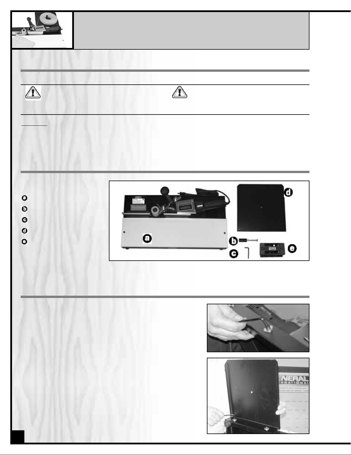
UNPACKING & SET UP
LIST OF CONTENTS
ASSEMBLY
SET UP SAFETY
This machine may present serious injury hazards
to untrained users. Be sure to read through this
entire manual and become familiar with the
controls, operations and specific hazards before
starting the machine!
Be sure to complete the entire set up and assembly process before plugging in and turning on the
machine.
UNPACKING
Carefully unpack and remove the unit and its components from its box and check for missing or damaged items
as per the list of contents below.
Note: Please report any damaged or missing items to your General International distributor immediately.
EDGE BANDER
STUD,HEX HEAD BOLT & NUT
ALLEN WRENCH
SUPPORT TABLE
DOUBLE EDGE TRIMMER
Fig. 1
Fig. 2
INSTALLING SUPPORT TABLE
1. Tilt the Edge Bander up on its edge and using the supplied
5 mm allen wrench remove the two caps screws and flat
washers that are attached to the rear of the machine. (Fig.1)
2. Attach the support table to the rear of the machine using the
two caps screws and flat washers. (Fig. 2)
3. Unscrew the stud from the hex head bolt leaving the nut on the
bolt. (Fig. 3)
4. Insert the bolt through the hole in the center of the support table
from underneath. The hex nut on the bolt should be under the
support table. (Fig. 4)
5. Thread the stud onto the bolt from the top of the table (Fig.5).
4
Page 5

Fig. 4
Fig. 5
6. Adjust the bolt until the head is in contact with the surface of your table or bench allowing the bolt to serve
as a support for the table.
7. Secure the height of the bolt by tightening the hex nut up against the underside of the suppor t table.
Fig. 3
Make sure the voltage of your power supply matches the
specifications on the label affixed to the heat gun.The Edge
Bander is designed to run on standard 120 volt North
American "household" current.
EXTENSION CORDS
If an extension cord is necessary,make sure the cord rating
is suitable for the amperage listed on the machine's motor
plate. An undersized cord will cause a drop in line voltage
resulting in loss of power and overhea ting. The chart shows
the correct size cord to use based on cord length and motor
plate amp rating. If in doubt, use the next heavier gauge.
The smaller the gauge number the heavier the cord.
GROUNDING INSTRUCTIONS
EXTENSION CORD LENGTH*
AMPS
< 5
5 to 8
8 to 12
12 to 15
15 to 20
21 to 30
25 50 75 100 150 200
feet feet feet feet feet feet
16
16
14
12
10
10
16
16
14
12
10
NR
16
14
12
10
10
NR
14
12
10
10
NR
NR
12
10
NR
NR
NR
NR
12
NR
NR
NR
NR
NR
*Based on limiting the line voltage drop to 5V at 150% of the rated amperes.
NR: Not Recommended.
ADJUSTMENTS
UPPER AND LOWER GUIDES
The upper and lower guides can be adjusted by loosening the
cap screws (
) with the 5 mm hex wrench. (Fig.6) After adjustment,
re-tighten the screws.
The lower guides should be set slightly below the wor k table, after
which no further adjustments will be necessary for the lower guides.
Adjust the upper guides to suit the width of your banding material.
NOTE: The banding material must move freely through the guides.
INFEED AND OUTFEED FENCES
The infeed and outfeed fences are used to support the edge of the
workpiece.Both fences should be positioned in relation to the pinch
roller to allow for the thickness of the edge banding material being
used.Normally,the fences will be recessed about 1/32" to 3/64" from
the crown of the pinch roller,( Fig.7) This setting has already been
made before the Edge Bander was shipped; however you may wish
to double-check it.
It should also be checked occasionally as the edge bander
receives use.
If a fence requires adjustment,loosen the two cap screws (Fig.7) and
shift the fence forward or backward as needed.
Fig. 6
Fig. 7
5
Page 6

The main on-off switch is on the handle of the hot air gun (Fig.9).
The temperature of the heat is controlled by the dial (Fig.10); hotter
toward the red part of the dial, cooler toward the blue part of the
dial.
NOTE: The heat setting is arbitrary. The hotter the gun, the faster you
must feed the work. For best results, start with a low heat and make
adjustments according to your experience with the edge bander
and the material you are using.
OPERATING CONTROLS
Fig. 9
Fig. 10
NOTE:
To adjust the infeed fence, you must first remove the hot air
gun from the table as follows:
1. On the underside of the Edge Bander, use a Phillips screwdriver
to remove the two screws which secure the hot air gun (Fig.8).
2. Carefully remove the hot air gun from the table.The socket head
cap screws on the infeed fence will now be accessible; adjust
the infeed fence as needed.
3. When finished,re-install the hot air gun. Re-ins tall and tighten the two screws (Fig.8).
Fig. 8
The hot air gun should be disconnected from the power source.If the
hot air gun has just been used in an edge banding operation, allow
it to cool sufficiently before attempting to remove it.
SELECTION OF BANDING MATERIAL
The edge banding material must have a hot melt adhesive backing. The width of the edge banding material you select is dependent upon the thickness of the stock you are banding. The Edge
Bander will accept banding material up to 2-1/4" wide.
The banding material is usually no more than 1/16" wider than the
thickness of the workpiece. This means there is only about 1/32" of
excess to remove from either side of the workpiece, (Fig.11). This
allows the excess to be removed with a knife (not provided) or the
double edge trimmer.The excess may also be removed by sanding.
When the edge banding material is too wide, the clean-up job
becomes difficult and edge banding material is wasted.
BASIC PROCEDURE
1. Set the roll of edge banding material on the support table. The
banding material should be oriented so the adhesive backed
side will face the heat gun as it moves through the guides.
2. Make sure the lower guides have been set slightly below the
work table.This will place the bottom edge of the banding material slightly below the edge of the workpiece.
3. Slide the leading end of the banding material through the
guides, and adjust the upper guides to the width of the banding
material. (Fig.12)
OPERATION
Fig. 11
6
Fig. 12
Page 7

NOTE: The banding material must move freely through the guides.
4. Position the leading end of the banding material in front of the
nozzle of the hot air gun,(Fig.13)
5. Choose the desired heat setting on the temperature dial.
6. Plug the Edge Bander into the power source and turn on the
switch. Allow approximately 30 seconds for the hot air gun to
reach operating temperature.Adjust the temperature dial again
if necessary.
Fig. 13
7. As the hot melt adhesive softens at the front end of the banding
material, hand feed the banding material up to the crown of the
pinch roller. (Fig.14)
NOTE: A general indicator that the adhesive is hot enough is when it
begins to bubble slightly.
8. Place the workpiece on the table and against the infeed fence.
Fig.15.
9. Push the edge of the workpiece along the infeed fence and
against the edge banding material (Fig.15). The edge banding
material will be trapped between the pinch roller and the work
piece.The edge banding mater ial will bond to the workpiece.
10.Guide the workpiece along the pinch roller at a steady, moderate speed. The edge banding mater ial will continue to bond to
the edge of the workpiece and will be pulled through the guides
by the movement of the wor kpiece.
NOTE: Be sure the hot melt adhesive is bonding to the workpiece. If you
feed the workpiece too fast, or the hot air gun temperature is set too low,
the bond will be poor. Make adjustments as needed to obtain a good
bond.
11.As the workpiece is advanced (Fig.16), the leading edge of the
workpiece may be rested against the outfeed fence as well as
the pinch roller. Always maintain pressure on the pinch roller
while you are edge banding.
12. When the trailing end of the workpiece lines up with the scribed
mark on the infeed fence, push down on the plunge cutter firmly and rapidly to sever the edge banding material. (Fig.17)
13.Continue to push the workpiece forward until the entire edge of
the workpiece has been banded.The end of the banding material will extend slightly beyond the trailing end of the workpiece.
14.Shut off the hot air gun and allow it to cool completely before
storing the Edge Bander. When the Edge Bander is not being
used, unplug it from the power source.
Fig. 14
Fig. 15
Fig. 16
The hot air gun generates sufficient heat to burn flesh and ignite combustibles. Work with extreme caution. Do not
touch metal areas around the gun while it is turned on.
Fig. 17
7
Page 8

Prolonged use of the Edge Bander may cause accumulation of hot melt adhesive on the guides,which can
block free movement of the edge banding material.To remove this adhesive, plug in the tool and turn it on,
with the heat gun at a medium setting. Keep hands away from hot air gun. As the hea t gun softens the hot
melt adhesive,peel the adhesive from the guides with a putty knife.Be careful not to scratch the guides; they
must remain smooth for best results.
If the pinch roller needs cleaning, wipe it with soa p and water.Do not use solvents on the pinch roller.
If the power cord is worn, cut, or damaged in any way, have it replaced immediately.
MAIN TABLE REPLACEMENT
The laminated front table may eventually become scuffed with use. It can be replaced with any smooth
faced stock.Remove the old table by unscrewing and removing the two socket head flat screws,(Fig.20) with
a 5/32" (or 4mm) hex wrench. Use the old table as a pattern for cutting the new one.
A plastic laminate face may be glued to the new table. This will
increase its durability and reduce friction between the table and the
workpiece. Be sure the new table is the same thickness as the
original. Make an allowance for the plastic laminate if you plan to
laminate your new work table.
Fig. 20
Before doing maintenance on the Edge Bander, unplug it from the power source, unless specified otherwise.
15.Trim the excess banding material from the workpiece. This can
be done easily with the Double Edge Trimmer pro vided with your
Edge Bander. (Fig.18)
16.The Double Edge Trimmer will work on materials 1/2" to 1" thick.
Simply place the Trimmer over the banded edge of the
workpiece and squeeze the Trimmer firmly to clamp it against
the workpiece edge. Continue to squeeze it firmly, and slide the
Trimmer down the edge of the workpiece in the direction of the
arrows, (Fig.18). Use steady,even pressure for best results.
18.A sharp knife (not supplied with your edge bander), Fig.19 is an
alternative method for trimming the excess banding material.
The excess may also be sanded off in some cases.
Fig. 18
8
Fig. 19
Page 9

TROUBLESHOOTING THE 45-100 BANDER
PROBLEM PROBABLE CAUSE SOLUTION
EDGE BANDER
WILL NOT TURN ON.
1. Not connected to power
source.
2. Fuse blown, or circuit breaker
tripped.
3. Cord damaged.
4. Hot air gun motor damaged.
1. Check plug connection.
2. Replace fuse, or reset circuit
breaker.
3. Replace cord.
4. Have hot air gun repaired or
replaced.
EDGE BANDER WILL
NOT HEAT.
1. Temperature dial not set
properly.
2. Hot air gun motor damaged.
1. Turn temperature dial toward
the red.
2. Have hot air gun repaired or
replaced.
EDGE BANDING MATERIAL DOES NOT FEED
SMOOTHLY THROUGH
GUIDES.
1. Guides not adjus ted properly.
2. Guides need cleaning.
1. Position guides according to
width of edge banding material.
2. Follow instr uctions for cleaning off
old adhesive from guides.
EDGE BANDING MATERIAL WILL NOT BOND TO
WORKPIECE.
1. Hot air gun not hot enough.
2. Feed rate too fast for heat
level.
3. Infeed and/or outfeed fence
not set properly.
4. Edge banding ma terial does
not have hot melt backing,or
has poor adhesive or is
defective.
1. Turn temperature dial toward the
red to increase heat.
2. Reduce feed ra te, or increase
heat level.
3. Fences should be recessed 1/32"
to 3/64" from crown of pinch
roller.
4. Replace edge banding ma terial.
EDGE BANDING
MATERIAL IS
DIFFICULT TO CUT.
1. Plunge cutter being pushed
down too lightly or slowly.
2. Knives in plunge cutter unit
are dull.
1. Push down plunge cutter rapidly
and firmly.
2. Replace knives in plunge cutter
unit.
91011
Page 10

Page 11

PAR TS LIST
45-100
PART N0. DESCRIPTION SPECIFICATION QTY
45100-01 SUPPORT TABLE 1
45100-02 STUD 1
45100-03 CAP SCREW M6X10 16
45100-04 FLAT WASHER M6X20 7
45100-05 UPPER EDGE GUIDE 2
45100-06 ROLLER 1
45100-07 BALL BEARING ZZ 2
45100-08 CAP SCREW M10X80 1
45100-09 PHILLIPS PAN HEAD MACHINE SCREW M5X16 3
45100-10 HANDLE (RIGHT) 1
45100-11 HANDLE (LEFT) 1
45100-12 NYLON LOCK HEX NUT M6 2
45100-13 RETAINING CLAMP SCREW M5X60 2
45100-14 FLAT WASHER M5 2
45100-15 HEAT SHIELD 1
45100-16 TOP RETAINING CLAMP 1
45100-17 BOTTOM RETAINING CLAMP 1
45100-18 NOZZLE 70236 1
45100-19 HOT AIR GUN WITH ELECTRIC CORD 1
45100-21 SOCKET HEAD FLAT SCREW M6X20 2
45100-22 WORK TABLE 1
45100-23 RUBBER FOOT 4
45100-24 CAP SCREW M6X16 4
45100-25 BASE 1
45100-26 FENCE 2
45100-27 PHILLIPS PAN HEAD MACHINE SCREW M5X16 2
45100-28 FLAT WASHER M8 4
45100-29 HEX NUT M8 2
45100-30 HEX NUT M10 1
45100-31 HEX NUT M6 5
45100-33 HEAT SHIELD 1
45100-34 FLAT WASHER M6 7
45100-35 STUD 2
45100-36 LOWER EDGE GUIDE 2
45100-37 CAP SCREW (FULL THREAD) M8X100 1
45100-38 HEX NUT M8 1
45100-39 CAP SCREW M6X16 1
45100-40 HEX NUT M5 1
45100-41 SPACER 1
45100-42 KNIFE GUARD (RIGHT) 1
45100-43 KNIFE BASE 1
45100-44 CAP SCREW M6X35 1
45100-45 SPRING 1
45100-46 UPPER KNIFE 1
45100-47 KNIFE GUARD (LEFT) 1
45100-48 BOTTOM KNIFE 1
45100-50 DOUBLE EDGE TRIMMER (NOT SHOWN) 1
Page 12

IMPORTANT: When ordering replacement parts, always give the model number, ser ial number of
the machine and part number. Also a brief description of each item and quantity
desired.
45-100
8360, Champ-d’Eau, Montreal (Quebec)
Canada H1P 1Y3
Tel.: (514) 326-1161
Fax : (514) 326-5565
Parts & Service
Fax : (514) 326-5555 Order Desk
orderdesk@general.ca
www.general.ca
 Loading...