

INSTALLATION INSTRUCTIONS
1
PRECAUTION: The installer should be an experienced service technician. Disconnect electrical power before
beginning installation. Do not install where temperatures fall below 32 degrees F or where plenum temperatures
exceed 200 degrees F. When wiring into a multi-speed blower circuit see Step 6C.
GENERALAire
RESIDENTIAL AIR TREATMENT PRODUCTS
FOR INSTALLATION ON A VERTICAL
PLENUM SURFACE OF ANY
FORCED AIR FURNACE
INST ALL ER: PLEASE FI LL O UT A ND M AI L GUARANTEE C ARD AFTER INSTALLATION
IS COMPLETE. LEAVE INSTALLATION
INSTRUCTION S WITH HOME OWNER
2
FLOW THROUGH
BYPASS HUMIDIFIER
R
3
COPPER
TUBING
PLASTIC
TUBING
Mount the self tapping saddle valve on either a cold or a hot water pipe. A
side or top mount is best to avoid clogging from pipe sediment. Connect 1/4”
O.D. tubing to the saddle valve. Copper tubing requires a brass compression
nut and brass sleeve. Plastic tubing requires a brass insert inside the tubing,
a plastic sleeve on the outside with a brass compression nut.
NOTE: DO NOT USE PLASTIC TUBING ON HOT WATER OR IN
CONTACT WITH ANY HOT PLENUM SURFACE OR DUCT.
INSTALLATION OF THIS SADDLE VALVE MUST MEET OR EXCEED
LOCAL CODES AND ORDINANCES.
4
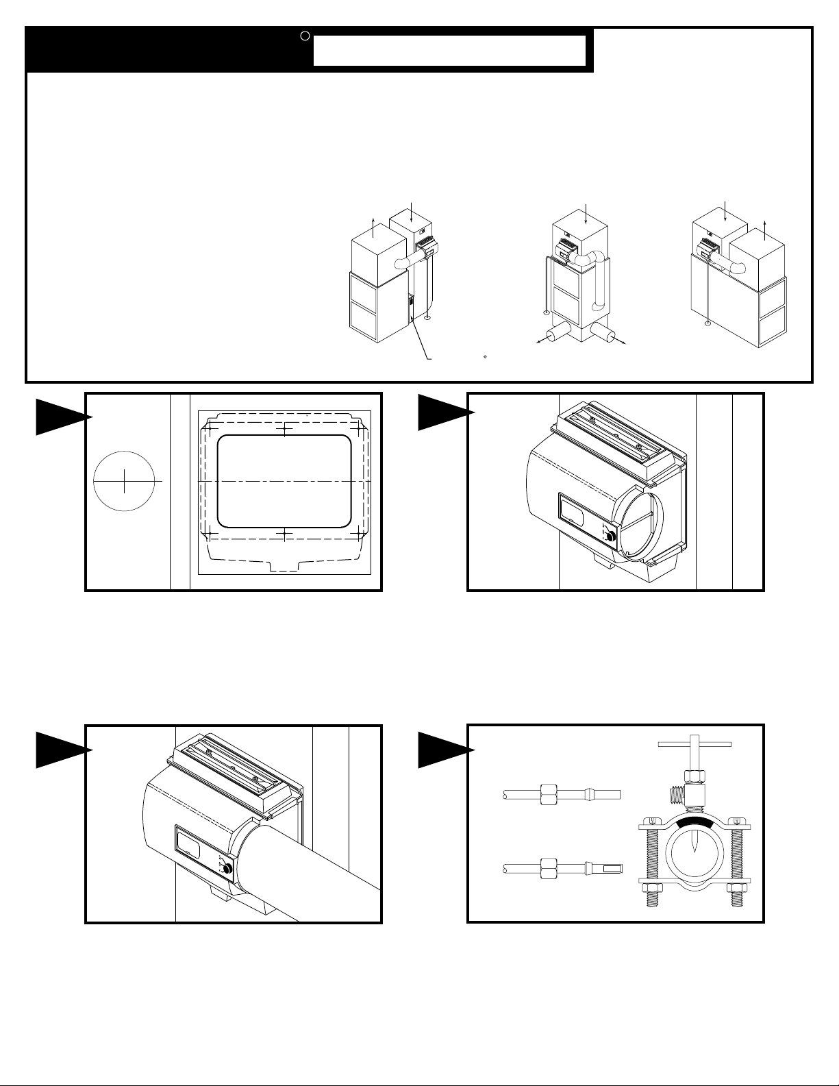
INSTALLATION: The humidifier may be mounted with the
7" outlet to the right or left by inverting the cabinet and
reversing the positions of the distributor trough and drain
pan. The humidifier may be mounted on the warm or
return air plenum with equal efficiency.
See Typical Installations.
ADDITIONAL MATERIALS THAT MAY BE NECESSARY:
1. 1/4" diameter plastic supply tubing or 1/4" copper
supply tubing for hot water applications
2. 7" diameter galvanized by-pass pipe
3. electrical wire and wire nuts
4. air pressure switch (G.F. Model #12500 suggested)
MODEL 1099
Install connecting collar and connect 7" elbow and by-pass pipe to
collar and humidifier cabinet. USE UNCRIMPED END IN
HUMIDIFIER CABINET. Using holes at top and bottom of humidifier
bypass opening drill 2---1/8" holes through bypass pipe and screw bypass pipe to humidifier cabinet.
Select location on vertical surface of warm or return air plenum for
mounting humidifier. Stick mounting template in place making sure the
template is level. Do not install humidifier or 7" bypass pipe where the
blanked off ends of a cooling coil will restrict air flow to the humidifier.
Extend horizontal centerline from template to the adjacent plenum. Scribe
7” circle 10” to 15” from side of humidifier, on cabinet centerline, using
connecting collar as guide.
Center punch and drill all six mounting holes as shown on template.
Cut out center section
of template and 7” hole
. Install all six cabinet
screws. Install drain pan, evaporator pad and distributor trough using
the four slide clips provided.
HIGH BOY COUNTER-FLOW LOW BOY
RETURN AIR
RETURN AIR
RETURN AIR
WARM AIR
WARM AIR
WARM AIR
WARM AIR
GENERALAire
AC SERIES
HIGH EFFICIENCY AIR CLEANER
R
DRAIN
DRAIN
DRAIN
Haut de la matrice
MATRICE POUR L'INSTALLATION
D'UN HUMIDIFICATEUR DE DÉRIVATION
COUPER SUR CETTE LIGNE
ALLOW 2 1/2 INCHES CLEARANCE ABOVE
THIS SURFACE FOR SERVICING
LAISSER 2 PO D'ESPACE LIBRE AU DESSUS
DE CETTE SURFACE POUR L'ENTRETIEN
SUIVRE LES INSTRUCTIONS DANS L'EMBALLAGE DE
L'HUMIDIFICATEUR
1. RETIRER LE PAPIER PROTECTEUR DU DOS DE LA
MATRICE ET COLLER À NIVEAU.
2.
3. DÉCOUPER LA PARTIE DU MILIEU DE LA MATRICE.
4. RETIRER LE RESTANT DE LA MATRICE.
ALLONGER CETTE LIGNE AFIN DE SITUER LE TROU SUR
LE PLÉNUMADJACENT
5.
6.
7.
Top Of Template
TEMPLATE FOR INSTALLING
BYPASS HUMIDIFIER
CUT ON THIS LINE
FOLLOW INSTRUCTIONS PACKED WITH HUMIDIFIER
1. REMOVE PROTECTIVE PAPER FROM BACK OF
TEMPLATEAND STICK IN LEVEL POSITION.
2. CENTER PUNCH AND DRILLTHETHREE TOP
MOUNTING HOLES WITH A 3/32" OR 1/8 " DIA. DRILL.
3. CUT OUT CENTER SECTION OF TEMPLATE.
4. REMOVE REMAINING TEMPLATE.
EXTENDTHIS LINE FOR LOCATING HOLE ON ADJACENT
PLENUM
5. INSTALL CABINET WITH THREETOP SCREWS.
6. LEVEL CABINETANDTIGHTEN SCREWS.
7. DRILLAND INSTALL BOTTOM SCREWS.
TEMPLATE NO. 1099-29
MATRICE NO. 1099-29
SADDLE VALVE INSTALLATION INSTRUCTIONS
Copper Pipe
1. Retract piercing pin into valve body by turning handle
counterclockwise.
2. Screw valve body into upper bracket and tighten.
3. Place rubber gasket over piercing pin.
4. Assemble saddle valve over copper pipe using enclosed screws,
nuts and lower bracket.
5. Tighten screws evenly and firmly. Brackets should be parallel.
6. Complete compression connection to saddle valve outlet.
7. Turn handle clockwise to pierce tubing and close saddle valve.
8. Turn handle counterclockwise to
open saddle valve, leave open for
several seconds to flush dirt from pipe and tubing.
Steel, Brass or Hard Plastic Pipe
1. Shut off water supply and drain pipe.
2. Turn handle clockwise to expose piercing pin and close saddle
valve.
3. Place rubber gasket over piercing pin.
4. Drill 1/8" hole in pipe using a hand crank drill to avoid shock hazard.
5. Assemble saddle valve over steel, brass or hard plastic pipe using
enclosed screws, nuts and lower bracket.
6. Tighten screws evenly and firmly. Brackets should be parallel.
7. Complete compression connection to saddle valve outlet.
8. Turn handle counterclockwise to
open saddle valve, leave open for
several seconds to flush dirt from pipe and tubing.
Threaded Pipe Fittings
1. Turn handle clockwise to expose piercing pin and close saddle
valve.
2. Seal valve body threads using pipe tape or sealant.
3. Install valve into 1/8" NPT fitting.
4. Complete compression connection to saddle valve outlet.
5. Turn handle counterclockwise to
open saddle valve, leave open for
several seconds to flush dirt from pipe and tubing.
5
Attach solenoid valve to side of humidifier cabinet with flow arrow
pointing up, using thumb nuts provided. Do not reverse brass
fittings as valve will not function if flow is reversed. Inlet and outlet
ports on valve may be reversed by loosening hex nut on solenoid
coil and rotating valve 1/2 turn. Assemble distributor tube so that it
is directed into the center opening of the distributor trough cover.
Connect 1/4" water supply tube to brass filter at inlet of solenoid.
DO NOT USE PLASTIC TUBING IN CONTACT WITH ANY
HOT PLENUM SURFACE OR DUCT. IF USING PLASTIC
TUBING, USE TUBE SUPPORT PROVIDED.
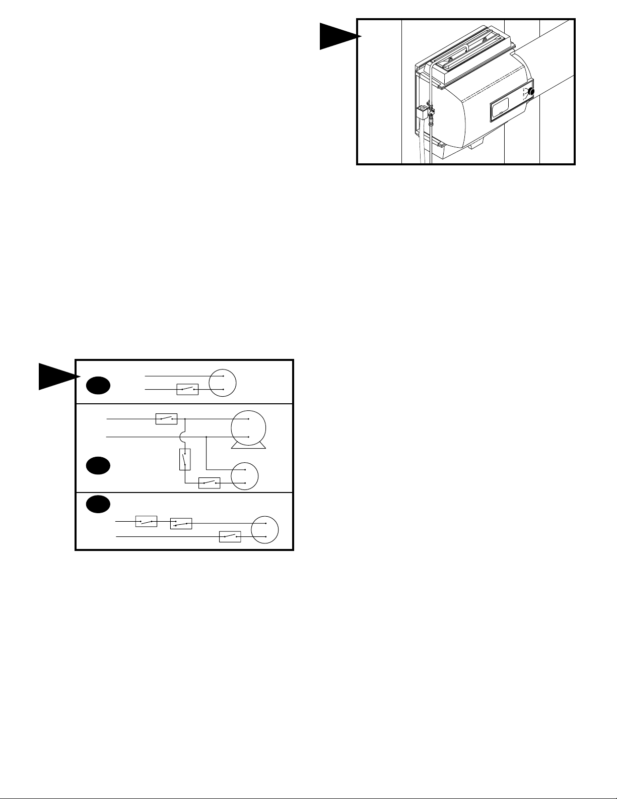
6
6 A
115v.
60CY.
6 B
6 C
115v.
60CY.
L1
(HOT)
L2
60CY.
L1
(HOT)
L2
115v.
ACC
EAC
(HOT)
C
FAN CONTROL
ON-OFF
SWITCH
ON-OFF
SWITCH
NO
HUMIDISTAT
12500 AIR
PRESSURE
SWITCH
HUMIDISTAT
HUMIDISTAT
C
HUMIDIFIER
115v. SOLENOID
VALVE
SINGLE
SPEED
BLOWER
MOTOR
HUMIDIFIER
115v.
SOLENOID
VALVE
HUMIDIFIER
115v. SOLENOID
VALVE
INSTRUCTIONS FOR WIRING
FIG. 6A WITH FURNACE CIRCUIT BOARD
On furnaces with output terminals ACC, or EAC check output voltage
to determine if terminals are 115V.
FIG. 6B WITH SINGLE SPEED BLOWER MOTOR
On furnaces with single speed blowers, wire the 115v. solenoid valve
in parallel with the blower circuit and install a manual on-off switch in
series with the 115v. solenoid valve.
FIG. 6C WITH TWO SPEED BLOWER MOTOR OR OUTSIDE
FURNACE CIRCUIT
On furnaces with a two speed blower motor or when wiring within the
furnace is not practical, the humidifier and a Model 12500 Air
Pressure Switch may be wired from a continuous 115 volt power
source. Install the on/off switch and Air Pressure Switch in series with
the 115v. solenoid valve on the hot or black wire. The Air Pressure
Switch will detect furnace operation and supply power to the
humidifier accordingly.
NOTE: ALL WIRING SHOULD COMPLY WITH LOCAL
ELECTRICAL CODES.

FORM NO. 1099-30 REV. B (FILE 12428)
PARTS LIST FOR HUMIDIFIER
Turn on water supply and check operation of humidifier. Set
humidistat to a demand setting. With the furnace off, the
solenoid valve should be closed. Start the furnace, the
solenoid valve should open when the blower or burner circuit
is energized. Check flow of water through distributor trough
and evaporator pad. The standard 990-16-75 orifice will
supply approximately 4.8 GPH of water at a line water
pressure of 60 psi. For low water pressures (20-40 psi) a
larger orifice 990-16-74 is available to provide the same
flow.
Connect drain hose to 5/8" spout on humidifier cabinet using
hose clamp provided. Run 5/8" hose to suitable drain such
as floor drain, sewer or laundry sink. Be sure hose has
continuous slope and is not kinked at any point.
7
8
Litho in U.S.A.
FILL OUT AND MAIL THIS
WARRANTY CARD AND
LITERATURE REQUEST FORM
AIRC
LEANERS AND AIRPURIFIERS
H
UMIDIFIERS
D
IGITALHUMIDITYGAGE
AIRF
ILTERGAGE
F
UELOILFILTERS AND
A
CCESSORIES
1099-9 THUMB NUT
1099-8 TROUGH COVER
1099-2 DISTRIBUTOR TROUGH
1099-12 DISTRIBUTOR TUBE
1099-20 EVAPORATOR PAD
CABINET ASSEMBLY
1099-24 (115 V.)
P-103 COMPRESSION NUT
P-104 COMPRESSION SLEEVE
P-111 CONNECTOR
SOLENOID VALVE ASSEMBLY
1099-41 (115 V.)
990-37-75 ORIFICE & STRAINER
ASSEMBLY
990-16-75 ORIFICE FITTING
990-17 STRAINER SCREEN
990-18 STRAINER BODY
1099-7 SLIDE CLIP
1099-3 DRAIN PAN
P-163 HOSE CLAMP
1099-16 DRAIN TUBE

LIMITED WARRANTY
This humidifier, if properly registered by the return of the warranty registration card to the manufacturer, is warranted to the consumer against defects in
materials and workmanship for a period of one year from the date of installation. Evaporator pads, sleeves or plates are not covered by this limited
warranty or any other warranties. Any other defective parts will be repaired without charge except for removal, reinstallation and transportation costs. To
obtain repair service under this limited warranty, the consumer must send the defective part or the complete humidifier to the manufacturer.
THERE ARE NO EXPRESS WARRANTIES COVERING THIS HUMIDIFIER OTHER THAN AS SET FORTH ABOVE, THE IMPLIED WARRANTIES OF
MERCHANTABILITY AND FITNESS FOR A PARTICULAR PURPOSE ARE LIMITED IN DURATION TO ONE YEAR. THE MANUFACTURER
ASSUMES NO LIABILITY IN CONNECTION WITH THE INSTALLATION OR USE OF THIS PRODUCT, EXCEPT AS STATED IN THIS LIMITED
WARRANTY. THE MANUFACTURER WILL IN NO EVENT BE LIABLE FOR INCIDENTAL OR CONSEQUENTIAL DAMAGES.
This limited warranty gives you specific legal rights, and you may also have other rights which vary from state to state. Some states do not allow either
limitations on implied warranties, or exclusions from incidental or consequential damages, so the above exclusion and limitation may not apply to you.
Any questions pertaining to this limited warranty should be addressed to the manufacturer. (U.S.A.: The manufacturer has elected not to make available
the informal dispute settlement mechanism which is specified in the Magnuson-Moss Warranty Act.)
GENERAL FILTERS, INC. 43800 GRAND RIVER AVE. NOVI, MICHIGAN 48375-1115 WWW.GENERALAIRE.COM
CANADIAN GENERAL FILTERS, LTD. 39 CROCKFORD BLVD. SCARBOROUGH, ONTARIO M1R3B7 WWW.CGFPRODUCTS.COM
CARE AND MAINTENANCE
Your Humidifier is engineered to give helpful and trouble-free humidification. For maximum efficiency the following cleaning procedures should be carried
out at the end of each heating season:
1. Turn off water supply and electrical power to humidifier.
2. Remove water distributor tube, distributor trough, evaporator pad and drain pan. The evaporator pad may be
removed from either the top or bottom of the humidifier. Clean excessive mineral deposits from the distributor trough,
cover, drain pan and humidifier cabinet. A solution of 1/2 vinegar & 1/2 water will help loosen mineral deposits.
3. If the evaporator pad has excessive mineral deposits, replace with a new “990-13” evaporator pad. Install trough
and drain pan. Replace cover and the distributor tube to proper position over the distributor trough.
4. In heavy mineral areas or if the solenoid valve fails to function disconnect the 1/4” water supply line from the
solenoid valve. Remove the brass strainer body (P.N. 990-18) from the solenoid valve. Carefully pull the strainer
screen (P.N. 990-17) from the orifice fitting (P.N. 990-16). Clean the mineral deposits from all parts. If the orifice is
clogged, it may be opened by inserting a small needle. Reinsert the filter into the orifice fitting and screw the brass
strainer body into the solenoid valve.
5. Reconnect the 1/4” water line to the solenoid valve if necessary. Turn on the water supply and check all points for
leakage. The operation of the unit may be checked by starting the furnace. The humidifier operates only when the
furnace blower is running or the burner circuit is energized. The humidifier is now ready for operation.
6. During the summer, turn off water supply and electrical power to humidifier. Close air damper.
AT
OUTSIDE
TEMPERATURE
-20 F -29 Cϒ 15%
-10 F -23 Cϒ 20%
0 F -18 Cϒ 25%
+10 F -29 C
ϒ 30%
+20 F - 7 C
ϒ 35%
+30 F - 1 Cϒ 40%
RECOMMENDED
ϒ
ϒ
ϒ
ϒ
ϒ
ϒ
SETTING
OWNER FILL IN
REGISTRATIO
AND MAIL TO
D
C
ATE OF
ITY
:
I
NSTALLATION:
D
S
TREET
C
EALER'S
ITY
:
A
DDRESS
N
AME
:
:
S
TATE
:
S
ERIAL
N
UMBER:
P
OSTAL
C
ODE
S
TATE
:
P
OSTAL
C
ODE
O
S
TREET
WNER'S NAME
A
DDRESS
:
:
MODEL 1099 Flow Through Bypass Humidifier
WARRANTY REGISTRATION
:
N
GENERAL FILTERS, INC.
43800 GRAND RIVER AVE
NOVI, MI 48375-1115
economical means of evaporating water to the air. The humidifier uses only
six watts of electrical power during operation, less than the smallest
household light bulb. The heat necessary for evaporating water is produced
by the furnace.
The water supply to the humidifier is controlled by the electric solenoid
valve.
HUMIDITY TOO HIGH DURING COLD WEATHER. EXCESSIVE
HUMIDITY MAY CAUSE CONDENSATION ON WINDOWS OR IN WALLS.
Water flows through a strainer, is metered through an orifice to provide the
proper amount of water, and is supplied to the evaporator pad by the
distributor trough. Approximately 200 CFM of air is by-passed from the
warm air plenum through the humidifier and returned to the cold air plenum.
Moisture is evaporated to the air passing through the evaporator pad.
Minerals are not blown into the air stream as occurs in atomizing
humidifiers; they are left on the evaporator pad where a high percentage is
carried off with the waste water.
necessary other than setting the control knob on the humidifier to the
desired level of humidification.
To turn the humidifier off, close water supply valve, switch electrical power
off and turn humidistat off. If furnace is used for summer cooling or
ventilating set air damper on "LOW" or "SUMMER".
HOW THE HUMIDIFIER WORKS
The operating principle of the humidifier is based on the most efficient and
ELECTRICAL RATING: 115 VAC / 60 Hz. DO NOT SET RELATIVE
When the humidifier is installed and operating, no adjustments are
:
:
 Loading...