


ZBD6900D00II
GE ZBD6900D00II, ZBD6900V00II, ZBD6900V50II, ZBD6920D00SS, ZBD6920V00SS Installation Guide
...
Instollotion
Instructions
Built-In Dishwoshers
*Custom front panel models include c_kit that
contains c_templote, hardware and panel
installation instructions. Refer to the kit
instructions when installing the custom panel.
[31-30281 I
05-11 GE
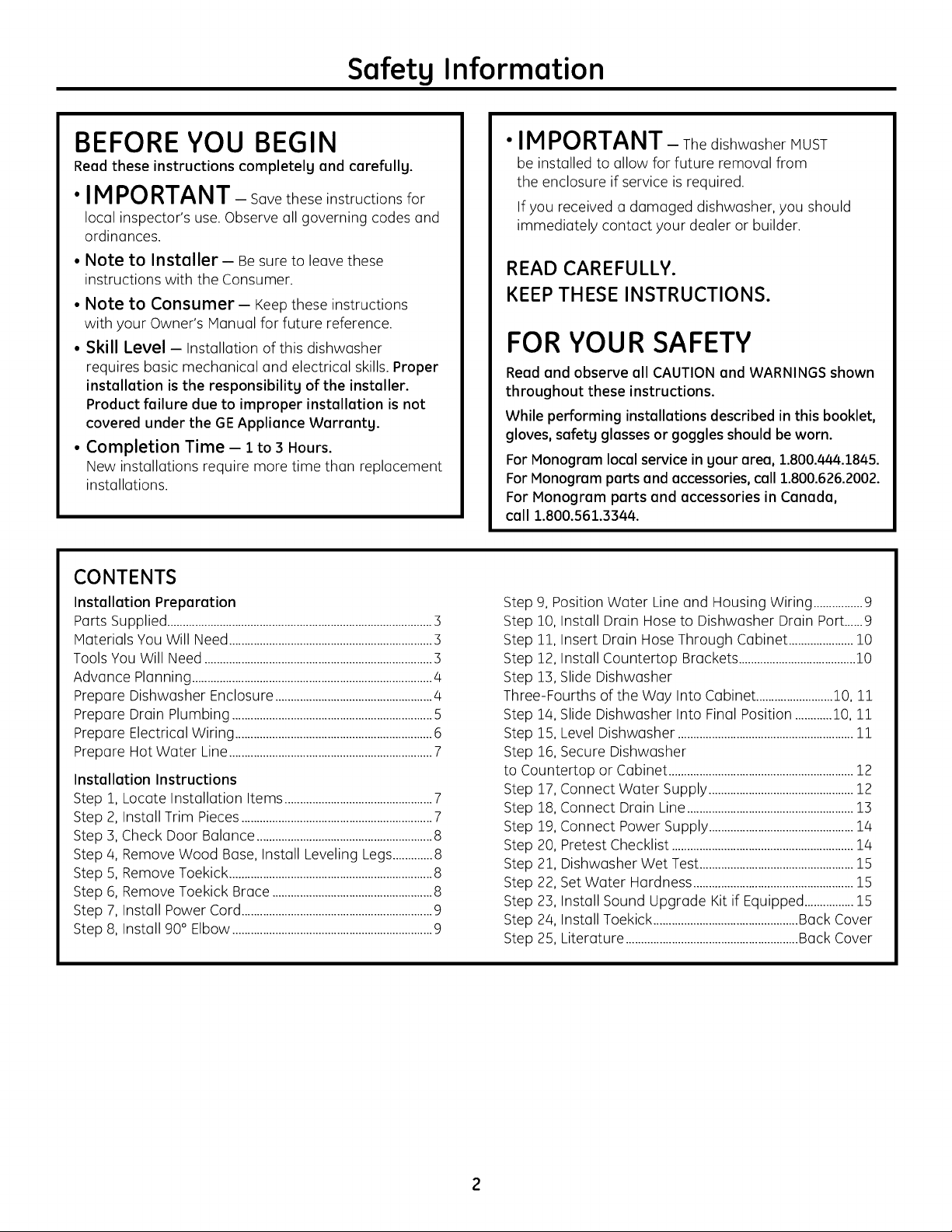
Safety Information
BEFORE YOU BEGIN
Read these instructions completely and carefully.
•IM PO RTANT - Savetheseinstructionsfor
localinspector'suse.Observe allgoverningcodes and
ordinances.
• Note to Installer-Be sure toleavethese
instructionswiththe Consumer.
• Note to Consumer- Keeptheseinstructions
with your Owner's Manual for future reference.
• Skill Level- Installation of this dishwasher
requires basic mechanical and electrical skills. Proper
installation is the responsibility of the installer.
Product failure due to improper installation is not
covered under the GE Appliance Warranty.
• Completion Time - 1 to 3 Hours.
New installations require more time than replacement
installations.
CONTENTS
Installation Preparation
Parts Supplied ......................................................................................3
Materials You Will Need ..................................................................3
Tools You Will Need ..........................................................................3
Advance Planning ..............................................................................4
Prepare Dishwasher Enclosure ...................................................4
Prepare Drain Plumbing .................................................................5
Prepare Electrical Wiring ................................................................6
Prepare Hot Water Line ..................................................................7
Installation Instructions
Step 1, Locate Installation Items ................................................7
Step 2,
Step :3,
Step 4,
Step 5,
Step 6,
Step 7,
Step 8,
Install Trim Pieces ..............................................................7
Check Door Balance .........................................................8
Remove Wood Base, Install Leveling Legs .............8
Remove Toekick ..................................................................8
Remove Toekick Brace ....................................................8
Install Power Cord ..............................................................9
Install 90° Elbow .................................................................9
•IMPORTANT- ThedishwasherMUST
be installedtoallowforfutureremoval from
the enclosureifserviceisrequired.
Ifyou receiveda damaged dishwasher,you should
immediately contactyour dealeror builder.
READ CAREFULLY.
KEEP THESE INSTRUCTIONS.
FOR YOUR SAFETY
Read and observe all CAUTIONand WARNINGS shown
throughout these instructions.
While performing installations described in this booklet,
gloves, safetg glasses or goggles should be worn.
For Monogram local service in your area, 1.800.444.1845.
For Monogram parts and accessories, call 1.800.626.2002.
For Monogram parts and accessories in Canada,
call 1.800.561.3344.
Step 9, Position Water Line and Housing Wiring ................9
Step 10, Install Drain Hose to Dishwasher Drain Port......9
Step 11, Insert Drain Hose Through Cabinet .....................l0
Step 12, Install Countertop Brackets ......................................10
Step 13, Slide Dishwasher
Three-Fourths of the Way Into Cabinet .........................10, 11
Step 1/4,Slide Dishwasher Into Final Position ............10, 11
Step 15, Level Dishwasher .........................................................11
Step 16,Secure Dishwasher
to Countertop or Cabinet ............................................................12
Step 17,Connect Water Supply...............................................12
18, Connect Drain Line ......................................................13
Step
19, Connect Power Supply ...............................................14
Step
20, Pretest Checklist ...........................................................14
Step
21, Dishwasher Wet Test ..................................................15
Step
22, Set Water Hardness ....................................................15
Step
23, Install Sound Upgrade Kit if Equipped ................15
Step
2/4, Install Toekick ...............................................Back Cover
Step
25, Literature ........................................................Back Cover
Step
Installation Preparation
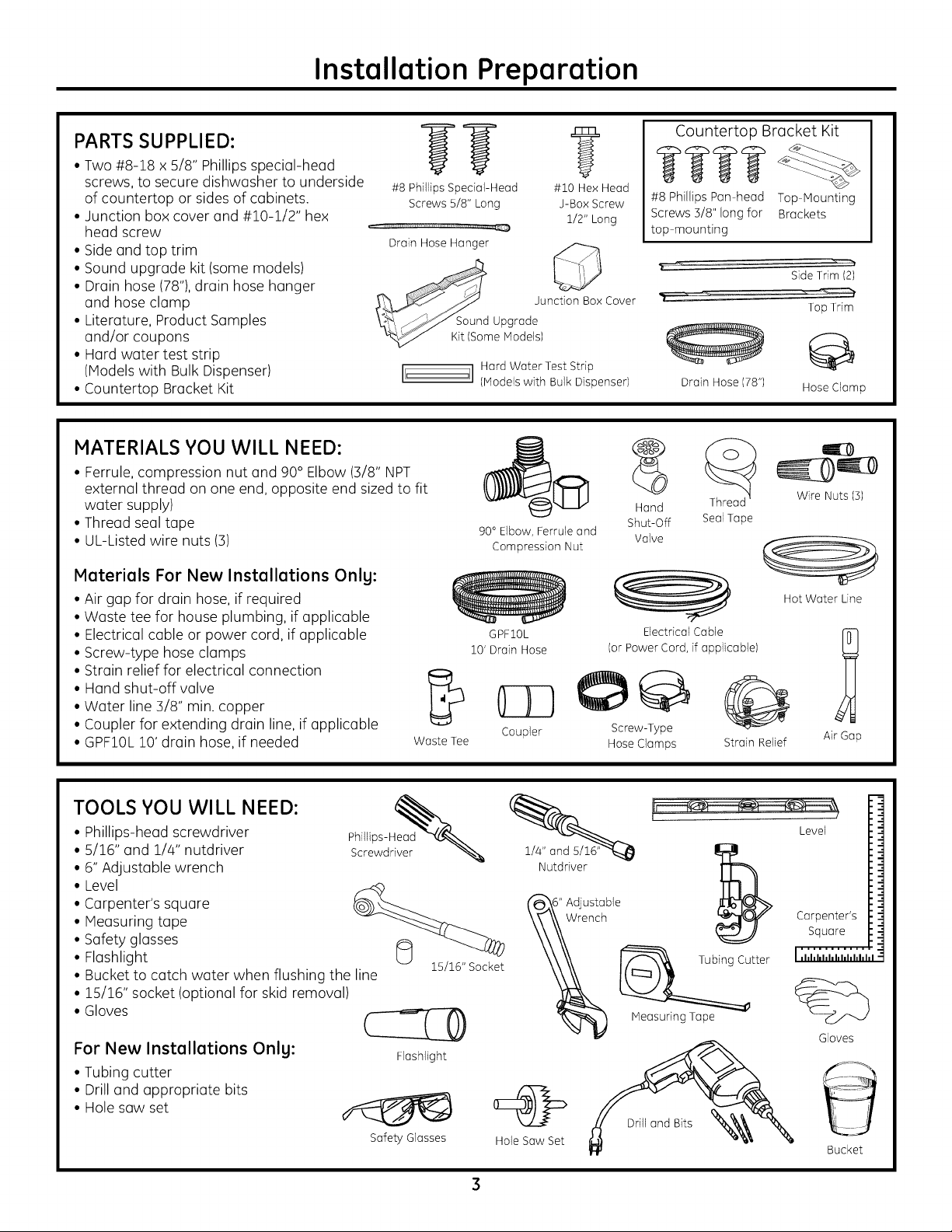
PARTS SUPPLIED:
• Two #8-18 x 5/8" Phillips special-head
screws, to secure dishwasher to underside
of countertop or sides of cabinets.
• Junction box cover and #10-1/2" hex
head screw
• Side and top trim
• Sound upgrade kit (some models)
• Drain hose (78"),drain hose hanger
and hose clamp
• Literature, Product Samples
and/or coupons
• Hard water test strip
(Models with Bulk Dispenser)
• Countertop Bracket Kit
#8 Phillips Special-Head #10 Hex Head
HI!iu'ml .....................................,H,u, ,U_
Drain Hose Hanger Q
MATERIALS YOU WILL NEED:
• Ferrule,compression nut and 90° Elbow (3/8" NPT
external thread on one end, opposite end sized to fit
water supply)
• Thread seal tape
• UL-Listed wire nuts (3)
Materials For New Installations Only:
• Air gap for drain hose, if required
• Waste tee for house plumbing, if applicable
• Electrical cable or power cord, if applicable
• Screw-type hose clamps
• Strain relief for electrical connection
• Hand shut-off valve
• Water line 3/8" min. copper
• Coupler for extending drain line, if applicable
• GPF10L10' drain hose, if needed
Screws 5/8" Long J-Box Screw
1/2" Long
Junction Box Cover
I[' ']1 Hard Water Test Strip
Waste Tee
(Models with Bulk Dispenser)
90° Elbow, Ferrule and
Compression Nut
GPFIOL
10'Drain Hose
Coupler Screw-Type
Countertop Bracket Kit
#8 Phillips Pan head Top Mounting
Screws5/8"longfor Brackets
top mounting
Drain Hose (78") Hose Clamp
Hand
Shut-Off Seal Tape
Valve
Electrical Cable
(or Power Cord, if applicable)
O
Hose Clamps
Strain Relief
SideTrim (2)
Top Trim
Wire Nuts (3)
Hot Water Line
1
Air Gap
TOOLS YOU WILL NEED:
• Phillips-head screwdriver
• 5/16" and 1/4" nutdriver
• 6" Adjustable wrench
• Level
• Carpenter's square
• Measuring tape
• Safety glasses
• Flashlight
• Bucket to catch water when flushing the line
• 15/16" socket (optional for skid removal)
• Gloves
For New Installations Only:
• Tubing cutter
• Drill and appropriate bits
• Hole saw set
?22w L
15/16" Socket
Safety Glasses
1/4" and
Nutdriver
Hole Saw Set
Tubing Cutter
MeasuringTape
Level
Carpenter's
Square
........... I
I ,hhhhl,hhhhhhl
%
Gloves
Bucket
ADVANCE PLANNING
Installation Preparation
• These dishwashers are designed for versatility,
adaptable to virtually any installation.
• All models have a full-length door without
the traditional access panel.
PREPARE DISHWASHER ENCLOSURE
This Wall Area
be Free
54-1/2" _+1//4"
Underside of
Countertop
to Floor
Figure A
/
,%
Floor MUST
be Even with
Room Floor
Pipes or wires
24"MJn.
Cabinets
Square
and
Plumb
• These dishwashers may be installed beneath
countertops of stone or other materials that will
not accept screws. No trim kit required.
kWARNING
To reduce the risk of electric shock, fire,
or injury to persons, the installer must
ensure that the dishwasher is completely
enclosed at the time of installation.
Special consideration for a dishwasher
installed on a elevated platform
The elevated platform must be flat
and level.
• The dishwasher must be installed no
s4" more than 10 feet from a sink for proper
Adjustable drainage.
toss" The dishwasher must be fully enclosed on
the top, sides and back.
• The dishwasher must not support any part
of the enclosure.
*Dishwasher models ZBD6900PII and ZBD8900PII require a 3/4" thick
custom panel and will be 24-3/4" deep.
• The rough cabinet opening must be at least 24"
deep, 24" wide and approximately 34-1/2" high
from floor to underside of the countertop.
• The back wall should be free of pipes or wires.
• Adjacent cabinets should be square and plumb
to ensure a good fit (Figure A).
• For a corner installation, allow 2" minimum
clearance between the dishwasher and the
adjacent wall.
• Plumbing and electrical service must enter
the shaded area.
• The dishwasher must be installed so that the drain
hose is no more than 10 feet in length for proper
drainage.
• Provide at least 28-3/8" in front of the dishwasher to
allow the dishwasher door to open fully (Figure B).
• IVlake sure the floor is level inside the opening and
even with the finished floor of the kitchen. This will
facilitate removal of the dishwasher at a later date
for service, if needed.
Figure B
I
Countertop
i
CLEARANCES:In a corner
installation, provide atleast
2" clearance between the
dishwasher and the adjacent
cabinet, wall or other
appliance.
Provide at least 28-3/8" of
clearance in front of the
dishwasher (Figure B).
4
Installation Preparation
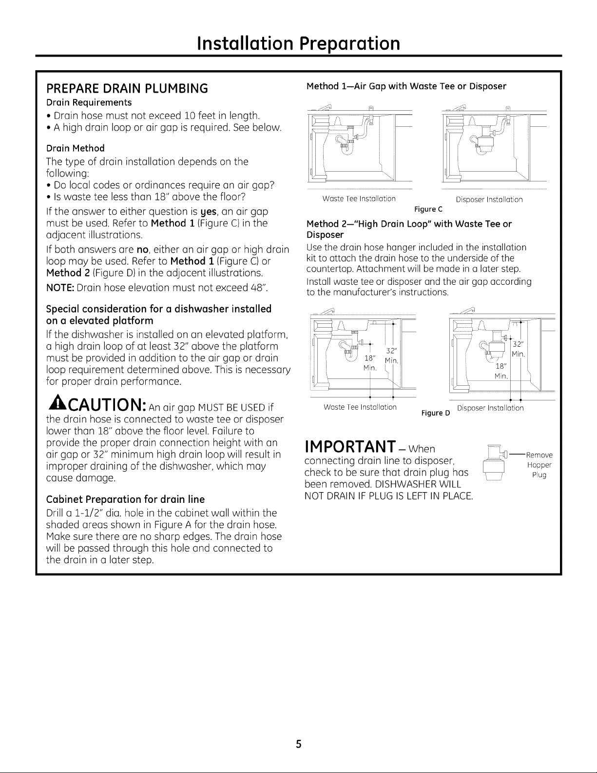
PREPARE DRAIN PLUMBING
Drain Requirements
• Drain hose must not exceed 10 feet in length.
• A high drain loop or air gap is required. See below.
Drain Method
The type of drain installation depends on the
following:
• Do local codes or ordinances require an air gap2
• Is waste tee less than 18" above the floor2
If the answer to either question is yes, an air gap
must be used. Refer to Method 1 (Figure C) in the
adjacent illustrations.
If both answers are no, either an air gap or high drain
loop may be used. Refer to Method 1 (Figure C)or
Method 2 (Figure D)in the adjacent illustrations.
NOTE: Drain hose elevation must not exceed 48".
Special consideration for a dishwasher installed
on a elevated platform
If the dishwasher is installed on an elevated platform,
a high drain loop of at least 32" above the platform
must be provided in addition to the air gap or drain
loop requirement determined above. This is necessary
for proper drain performance.
A,,-^, ,-,-,,,_,,,
_ll, k,,/_U/IUl_l: An airgap MUST BE USED if
the drain hose is connected to waste tee or disposer
lower than 18" above the floor level. Failure to
provide the proper drain connection height with an
air gap or 32" minimum high drain loop will result in
improper draining of the dishwasher, which may
cause damage.
Cabinet Preparation for drain line
Drill a 1-1/2" dia. hole in the cabinet wall within the
shaded ureas shown in Figure A for the drain hose.
Make sure there are no sharp edges. The drain hose
will be passed through this hole and connected to
the drain in a later step.
Method 1--Air Gap with Waste Tee or Disposer
Waste Tee Installation Disposer Installation
Figure C
Method 2--"High Drain Loop" with Waste Tee or
Disposer
Use the drain hose hanger included inthe installation
kit to attach the drain hose to the underside of the
countertop. Attachment will be made in a later step.
Install waste tee or disposer and the air gap according
to the manufacturer's instructions.
Waste Tee Installation
Figure D Disposer Installation
IMPORTANT- When
connectingdrainlineto disposer,
check tobe surethat drainplug has
been removed. DISHWASHER WILL
NOT DRAIN IFPLUG ISLEFT IN PLACE.
 Loading...