


 Loading...
GE |
|
Measurement & Control |
Flow |
DigitalFlow™ XGM868i
General-Purpose Gas Flow Transmitter (1 & 2 Channel)
Startup Guide
910-197U Rev. F1
February 2016

DigitalFlow™ XGM868i
General-Purpose Gas Flow Transmitter (1 & 2 Channel)
Startup Guide
910-197U Rev. F1
February 2016
www.gemeasurement.com
©2016 General Electric Company. All rights reserved. Technical content subject to change without notice.
[no content intended for this page]
ii
Preface
Information Paragraphs
Note: These paragraphs provide information that provides a deeper understanding of the situation, but is not essential to the proper completion of the instructions.
IMPORTANT: These paragraphs provide information that emphasizes instructions that are essential to proper setup of the equipment. Failure to follow these instructions carefully may cause unreliable performance.
CAUTION! This symbol indicates a risk of potential minor personal injury and/or severe damage to the equipment, unless these instructions are followed carefully.
WARNING! This symbol indicates a risk of potential serious personal injury, unless these instructions are followed carefully.
Safety Issues
WARNING! It is the responsibility of the user to make sure all local, county, state and national codes, regulations, rules and laws related to safety and safe operating conditions are met for each installation. The safety of any system incorporating the equipment is the responsibility of the assembler of the system.
Auxiliary Equipment
Local Safety Standards
The user must make sure that he operates all auxiliary equipment in accordance with local codes, standards, regulations, or laws applicable to safety.
Working Area
WARNING! Auxiliary equipment may have both manual and automatic modes of operation. As equipment can move suddenly and without warning, do not enter the work cell of this equipment during automatic operation, and do not enter the work envelope of this equipment during manual operation. If you do, serious injury can result.
WARNING! Make sure that power to the auxiliary equipment is turned OFF and locked out before you perform maintenance procedures on the equipment.
DigitalFlow™ XGM868i Startup Guide |
iii |
Preface
Qualification of Personnel
Make sure that all personnel have manufacturer-approved training applicable to the auxiliary equipment.
Personal Safety Equipment
Make sure that operators and maintenance personnel have all safety equipment applicable to the auxiliary equipment. Examples include safety glasses, protective headgear, safety shoes, etc.
Unauthorized Operation
Make sure that unauthorized personnel cannot gain access to the operation of the equipment.
Environmental Compliance
Waste Electrical and Electronic Equipment (WEEE) Directive
GE Measurement & Control is an active participant in Europe’s Waste Electrical and Electronic Equipment (WEEE) take-back initiative, directive 2012/19/EU.
The equipment that you bought has required the extraction and use of natural resources for its production. It may contain hazardous substances that could impact health and the environment.
In order to avoid the dissemination of those substances in our environment and to diminish the pressure on the natural resources, we encourage you to use the appropriate take-back systems. Those systems will reuse or recycle most of the materials of your end life equipment in a sound way.
The crossed-out wheeled bin symbol invites you to use those systems.
If you need more information on the collection, reuse and recycling systems, please contact your local or regional waste administration.
Visit www.gemeasurement.com/environmental-health-safety-ehs for take-back instructions and more information about this initiative.
iv |
DigitalFlow™ XGM868i Startup Guide |

Contents
Chapter 1. Installation
1.1 Introduction . . . . . . . . . . . . . . . . . . . . . . . . . . . . . . . . . . . . . . . . . . . . . . . . . . . . . . . . . . . . . . . . . . . . . . . . . . . . . . . . . . . . . . . . . . . .1 1.2 Unpacking . . . . . . . . . . . . . . . . . . . . . . . . . . . . . . . . . . . . . . . . . . . . . . . . . . . . . . . . . . . . . . . . . . . . . . . . . . . . . . . . . . . . . . . . . . . . .1 1.3 Site Considerations . . . . . . . . . . . . . . . . . . . . . . . . . . . . . . . . . . . . . . . . . . . . . . . . . . . . . . . . . . . . . . . . . . . . . . . . . . . . . . . . . . . . .2 1.3.1 Electronics Enclosure Location . . . . . . . . . . . . . . . . . . . . . . . . . . . . . . . . . . . . . . . . . . . . . . . . . . . . . . . . . . . . . . . . . . . . .2 1.3.2 Flowcell Location. . . . . . . . . . . . . . . . . . . . . . . . . . . . . . . . . . . . . . . . . . . . . . . . . . . . . . . . . . . . . . . . . . . . . . . . . . . . . . . . . .3 1.3.3 Transducer Location. . . . . . . . . . . . . . . . . . . . . . . . . . . . . . . . . . . . . . . . . . . . . . . . . . . . . . . . . . . . . . . . . . . . . . . . . . . . . . .3 1.3.4 Cable Lengths. . . . . . . . . . . . . . . . . . . . . . . . . . . . . . . . . . . . . . . . . . . . . . . . . . . . . . . . . . . . . . . . . . . . . . . . . . . . . . . . . . . . .3 1.3.5 Temperature and Pressure Transmitters . . . . . . . . . . . . . . . . . . . . . . . . . . . . . . . . . . . . . . . . . . . . . . . . . . . . . . . . . . . .3 1.3.6 Transducer Cables . . . . . . . . . . . . . . . . . . . . . . . . . . . . . . . . . . . . . . . . . . . . . . . . . . . . . . . . . . . . . . . . . . . . . . . . . . . . . . . .3 1.4 Installing a Flowcell. . . . . . . . . . . . . . . . . . . . . . . . . . . . . . . . . . . . . . . . . . . . . . . . . . . . . . . . . . . . . . . . . . . . . . . . . . . . . . . . . . . . .4
1.5 Installing Temperature and Pressure Transmitters. . . . . . . . . . . . . . . . . . . . . . . . . . . . . . . . . . . . . . . . . . . . . . . . . . . . . . . .4 1.6 Mounting the XGM868i Electronics Enclosure . . . . . . . . . . . . . . . . . . . . . . . . . . . . . . . . . . . . . . . . . . . . . . . . . . . . . . . . . . . .5 1.7 Making the Electrical Connections. . . . . . . . . . . . . . . . . . . . . . . . . . . . . . . . . . . . . . . . . . . . . . . . . . . . . . . . . . . . . . . . . . . . . . .5 1.7.1 Wiring the Line Power . . . . . . . . . . . . . . . . . . . . . . . . . . . . . . . . . . . . . . . . . . . . . . . . . . . . . . . . . . . . . . . . . . . . . . . . . . . . .7 1.7.2 Wiring the Transducers . . . . . . . . . . . . . . . . . . . . . . . . . . . . . . . . . . . . . . . . . . . . . . . . . . . . . . . . . . . . . . . . . . . . . . . . . . . .8 1.7.3 Wiring Std 0/4-20 mA Analog Outputs . . . . . . . . . . . . . . . . . . . . . . . . . . . . . . . . . . . . . . . . . . . . . . . . . . . . . . . . . . . . 10 1.7.4 Wiring the Serial Port . . . . . . . . . . . . . . . . . . . . . . . . . . . . . . . . . . . . . . . . . . . . . . . . . . . . . . . . . . . . . . . . . . . . . . . . . . . . 11 1.7.5 Wiring the Option Cards . . . . . . . . . . . . . . . . . . . . . . . . . . . . . . . . . . . . . . . . . . . . . . . . . . . . . . . . . . . . . . . . . . . . . . . . . 14
Chapter 2. Initial Setup
2.1 Introduction . . . . . . . . . . . . . . . . . . . . . . . . . . . . . . . . . . . . . . . . . . . . . . . . . . . . . . . . . . . . . . . . . . . . . . . . . . . . . . . . . . . . . . . . . . 29 2.2 Programming Methods . . . . . . . . . . . . . . . . . . . . . . . . . . . . . . . . . . . . . . . . . . . . . . . . . . . . . . . . . . . . . . . . . . . . . . . . . . . . . . . 29 2.3 The XGM868i Enclosure Keypad . . . . . . . . . . . . . . . . . . . . . . . . . . . . . . . . . . . . . . . . . . . . . . . . . . . . . . . . . . . . . . . . . . . . . . . 30 2.4 Entering Data in the Global Menu . . . . . . . . . . . . . . . . . . . . . . . . . . . . . . . . . . . . . . . . . . . . . . . . . . . . . . . . . . . . . . . . . . . . . 32 2.4.1 Entering Global System Data. . . . . . . . . . . . . . . . . . . . . . . . . . . . . . . . . . . . . . . . . . . . . . . . . . . . . . . . . . . . . . . . . . . . . 32 2.5 Activating a Channel. . . . . . . . . . . . . . . . . . . . . . . . . . . . . . . . . . . . . . . . . . . . . . . . . . . . . . . . . . . . . . . . . . . . . . . . . . . . . . . . . . 35
2.6 Entering System Data for the Channel . . . . . . . . . . . . . . . . . . . . . . . . . . . . . . . . . . . . . . . . . . . . . . . . . . . . . . . . . . . . . . . . . 36 2.7 Entering Transducer and Pipe Parameters . . . . . . . . . . . . . . . . . . . . . . . . . . . . . . . . . . . . . . . . . . . . . . . . . . . . . . . . . . . . . 37 2.7.1 Special Transducers . . . . . . . . . . . . . . . . . . . . . . . . . . . . . . . . . . . . . . . . . . . . . . . . . . . . . . . . . . . . . . . . . . . . . . . . . . . . . 38 2.7.2 Pipe Data . . . . . . . . . . . . . . . . . . . . . . . . . . . . . . . . . . . . . . . . . . . . . . . . . . . . . . . . . . . . . . . . . . . . . . . . . . . . . . . . . . . . . . . 38
Chapter 3. Operation
3.1 Introduction . . . . . . . . . . . . . . . . . . . . . . . . . . . . . . . . . . . . . . . . . . . . . . . . . . . . . . . . . . . . . . . . . . . . . . . . . . . . . . . . . . . . . . . . . . 43 3.2 Powering Up . . . . . . . . . . . . . . . . . . . . . . . . . . . . . . . . . . . . . . . . . . . . . . . . . . . . . . . . . . . . . . . . . . . . . . . . . . . . . . . . . . . . . . . . . 44 3.3 The LCD Display . . . . . . . . . . . . . . . . . . . . . . . . . . . . . . . . . . . . . . . . . . . . . . . . . . . . . . . . . . . . . . . . . . . . . . . . . . . . . . . . . . . . . . 45 3.4 The Optional PanaView Display . . . . . . . . . . . . . . . . . . . . . . . . . . . . . . . . . . . . . . . . . . . . . . . . . . . . . . . . . . . . . . . . . . . . . . . 46 3.5 Taking Measurements . . . . . . . . . . . . . . . . . . . . . . . . . . . . . . . . . . . . . . . . . . . . . . . . . . . . . . . . . . . . . . . . . . . . . . . . . . . . . . . . 47
3.5.1 Programming the LCD . . . . . . . . . . . . . . . . . . . . . . . . . . . . . . . . . . . . . . . . . . . . . . . . . . . . . . . . . . . . . . . . . . . . . . . . . . . 47 3.5.2 Using the LCD Display . . . . . . . . . . . . . . . . . . . . . . . . . . . . . . . . . . . . . . . . . . . . . . . . . . . . . . . . . . . . . . . . . . . . . . . . . . . 49 3.5.3 PanaView Display . . . . . . . . . . . . . . . . . . . . . . . . . . . . . . . . . . . . . . . . . . . . . . . . . . . . . . . . . . . . . . . . . . . . . . . . . . . . . . . 50 3.5.4 Pausing Measurement. . . . . . . . . . . . . . . . . . . . . . . . . . . . . . . . . . . . . . . . . . . . . . . . . . . . . . . . . . . . . . . . . . . . . . . . . . . 53
DigitalFlow™ XGM868i Startup Guide |
v |

Contents
Chapter 4. Specifications
4.1 General Specifications . . . . . . . . . . . . . . . . . . . . . . . . . . . . . . . . . . . . . . . . . . . . . . . . . . . . . . . . . . . . . . . . . . . . . . . . . . . . . . . . .55
4.1.1 Hardware Configuration . . . . . . . . . . . . . . . . . . . . . . . . . . . . . . . . . . . . . . . . . . . . . . . . . . . . . . . . . . . . . . . . . . . . . . . . . .55
4.1.2 Environmental . . . . . . . . . . . . . . . . . . . . . . . . . . . . . . . . . . . . . . . . . . . . . . . . . . . . . . . . . . . . . . . . . . . . . . . . . . . . . . . . . . .55
4.1.3 Velocity Accuracy . . . . . . . . . . . . . . . . . . . . . . . . . . . . . . . . . . . . . . . . . . . . . . . . . . . . . . . . . . . . . . . . . . . . . . . . . . . . . . . .55
4.1.4 Velocity Range . . . . . . . . . . . . . . . . . . . . . . . . . . . . . . . . . . . . . . . . . . . . . . . . . . . . . . . . . . . . . . . . . . . . . . . . . . . . . . . . . . .56
4.1.5 Rangeability . . . . . . . . . . . . . . . . . . . . . . . . . . . . . . . . . . . . . . . . . . . . . . . . . . . . . . . . . . . . . . . . . . . . . . . . . . . . . . . . . . . . .56
4.1.6 Repeatability. . . . . . . . . . . . . . . . . . . . . . . . . . . . . . . . . . . . . . . . . . . . . . . . . . . . . . . . . . . . . . . . . . . . . . . . . . . . . . . . . . . . .56
4.2 Electrical Specifications. . . . . . . . . . . . . . . . . . . . . . . . . . . . . . . . . . . . . . . . . . . . . . . . . . . . . . . . . . . . . . . . . . . . . . . . . . . . . . . .56
4.2.1 Power Supply . . . . . . . . . . . . . . . . . . . . . . . . . . . . . . . . . . . . . . . . . . . . . . . . . . . . . . . . . . . . . . . . . . . . . . . . . . . . . . . . . . . .56
4.2.2 Power Consumption. . . . . . . . . . . . . . . . . . . . . . . . . . . . . . . . . . . . . . . . . . . . . . . . . . . . . . . . . . . . . . . . . . . . . . . . . . . . . .56
4.2.3 Operating Mode. . . . . . . . . . . . . . . . . . . . . . . . . . . . . . . . . . . . . . . . . . . . . . . . . . . . . . . . . . . . . . . . . . . . . . . . . . . . . . . . . .56
4.2.4 European Compliance . . . . . . . . . . . . . . . . . . . . . . . . . . . . . . . . . . . . . . . . . . . . . . . . . . . . . . . . . . . . . . . . . . . . . . . . . . . .56
4.2.5 Input/Output Specifications. . . . . . . . . . . . . . . . . . . . . . . . . . . . . . . . . . . . . . . . . . . . . . . . . . . . . . . . . . . . . . . . . . . . . . .57
4.2.6 Preamplifier. . . . . . . . . . . . . . . . . . . . . . . . . . . . . . . . . . . . . . . . . . . . . . . . . . . . . . . . . . . . . . . . . . . . . . . . . . . . . . . . . . . . . .58
4.3 Flow Transducer Specifications . . . . . . . . . . . . . . . . . . . . . . . . . . . . . . . . . . . . . . . . . . . . . . . . . . . . . . . . . . . . . . . . . . . . . . . .58
4.3.1 Physical . . . . . . . . . . . . . . . . . . . . . . . . . . . . . . . . . . . . . . . . . . . . . . . . . . . . . . . . . . . . . . . . . . . . . . . . . . . . . . . . . . . . . . . . .58
4.3.2 Area Classifications . . . . . . . . . . . . . . . . . . . . . . . . . . . . . . . . . . . . . . . . . . . . . . . . . . . . . . . . . . . . . . . . . . . . . . . . . . . . . .58
4.4 Flowcell Specifications. . . . . . . . . . . . . . . . . . . . . . . . . . . . . . . . . . . . . . . . . . . . . . . . . . . . . . . . . . . . . . . . . . . . . . . . . . . . . . . . .59
4.4.1 Spoolpiece. . . . . . . . . . . . . . . . . . . . . . . . . . . . . . . . . . . . . . . . . . . . . . . . . . . . . . . . . . . . . . . . . . . . . . . . . . . . . . . . . . . . . . .59
4.4.2 Cold Tap . . . . . . . . . . . . . . . . . . . . . . . . . . . . . . . . . . . . . . . . . . . . . . . . . . . . . . . . . . . . . . . . . . . . . . . . . . . . . . . . . . . . . . . . .59
4.4.3 Pipe Size & Materials . . . . . . . . . . . . . . . . . . . . . . . . . . . . . . . . . . . . . . . . . . . . . . . . . . . . . . . . . . . . . . . . . . . . . . . . . . . . .59
Appendix A. CE Mark Compliance
A.1 Introduction. . . . . . . . . . . . . . . . . . . . . . . . . . . . . . . . . . . . . . . . . . . . . . . . . . . . . . . . . . . . . . . . . . . . . . . . . . . . . . . . . . . . . . . . . . .61
A.2 Wiring . . . . . . . . . . . . . . . . . . . . . . . . . . . . . . . . . . . . . . . . . . . . . . . . . . . . . . . . . . . . . . . . . . . . . . . . . . . . . . . . . . . . . . . . . . . . . . . .61
Appendix B. Data Records
B.1 Available Option Cards . . . . . . . . . . . . . . . . . . . . . . . . . . . . . . . . . . . . . . . . . . . . . . . . . . . . . . . . . . . . . . . . . . . . . . . . . . . . . . . .63
B.2 Option Cards Installed . . . . . . . . . . . . . . . . . . . . . . . . . . . . . . . . . . . . . . . . . . . . . . . . . . . . . . . . . . . . . . . . . . . . . . . . . . . . . . . . .64
B.3 Setup Data. . . . . . . . . . . . . . . . . . . . . . . . . . . . . . . . . . . . . . . . . . . . . . . . . . . . . . . . . . . . . . . . . . . . . . . . . . . . . . . . . . . . . . . . . . . .65
Appendix C. Measuring P and L Dimensions
C.1 Introduction. . . . . . . . . . . . . . . . . . . . . . . . . . . . . . . . . . . . . . . . . . . . . . . . . . . . . . . . . . . . . . . . . . . . . . . . . . . . . . . . . . . . . . . . . . .69
C.2 Measuring P and L. . . . . . . . . . . . . . . . . . . . . . . . . . . . . . . . . . . . . . . . . . . . . . . . . . . . . . . . . . . . . . . . . . . . . . . . . . . . . . . . . . . . .69
vi |
DigitalFlow™ XGM868i Startup Guide |

Chapter 1. Installation
Chapter 1. Installation
1.1Introduction
To ensure safe and reliable operation of the Model XGM868i Ultrasonic Flow Transmitter, the system must be installed in accordance with the guidelines established by GE engineers. Those guidelines, which are explained in detail in this chapter, include the following specific topics:
•
•
•
Unpacking the Model XGM868i system
Selecting suitable sites for the electronics enclosure and the flowcell/transducers
Installing the flowcell/transducers
Note: See the enclosed Transducer Installation Guide for detailed instructions on transducer installation.
•
•
•
Installing optional temperature and pressure transmitters
Installing the electronics enclosure
Wiring the electronics enclosure
WARNING! The Model XGM868i flow transmitter can measure the flow rate of many gases, some of which are potentially hazardous. In such cases, the importance of proper safety practices cannot be overemphasized.
Be sure to follow all applicable local safety codes and regulations for installing electrical equipment and working with hazardous gases or flow conditions. Consult company safety personnel or local safety authorities to verify the safety of any procedure or practice.
!ATTENTION EUROPEAN CUSTOMERS!
To meet CE Mark requirements, all cables must be installed as described in Appendix A,
CE Mark Compliance.
1.2Unpacking
Carefully remove the electronics enclosure, the transducers, and the cables from the shipping containers. Before discarding any of the packing materials, account for all components and documentation listed on the packing slip. The discarding of an important item along with the packing materials is all too common. If anything is missing or damaged, contact the factory immediately for assistance.
DigitalFlow™ XGM868i Startup Guide |
1 |
Chapter 1. Installation
1.3Site Considerations
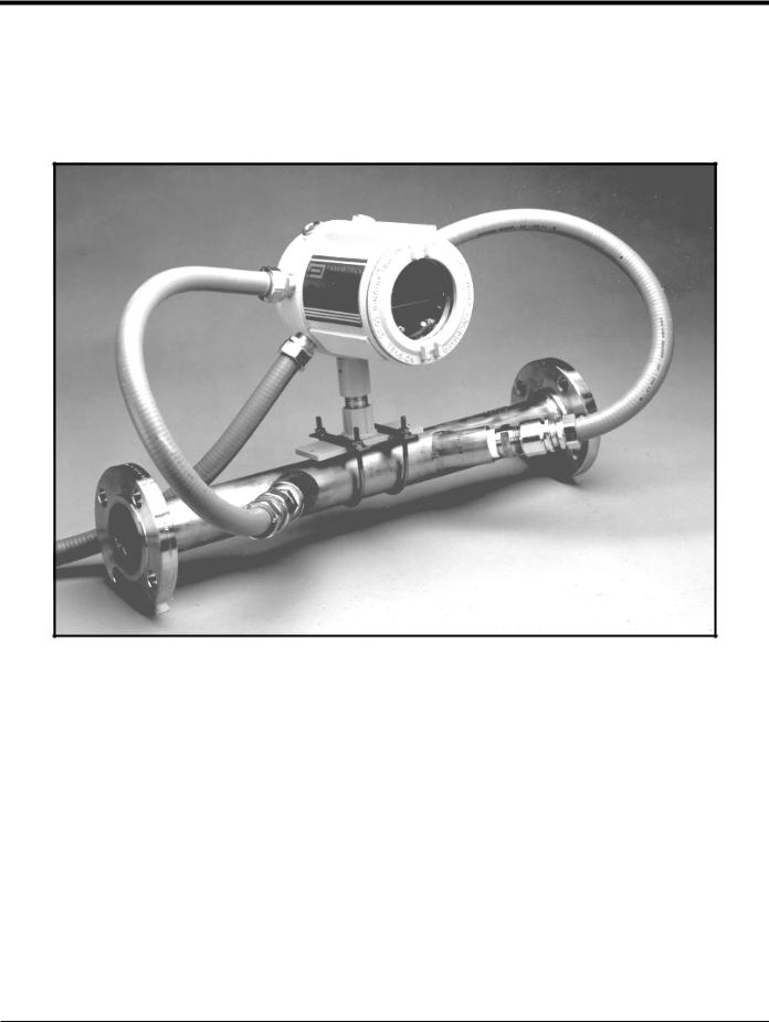
Because the relative location of the flowcell and the electronics enclosure is important, use the guidelines in this section to plan the XGM868i installation. Figure 1 shows a typical XGM868i enclosure and spoolpiece ready for insertion into a process line.
Figure 1: A Typical Model XGM868i System
1.3.1 Electronics Enclosure Location
The standard Model XGM868i electronics enclosure is a powder-coated, cast-aluminum, Type-7/4X explosion-proof enclosure; an optional stainless-steel enclosure is available. Typically, the enclosure is mounted as close as possible to the transducers. When choosing a site, make sure the location permits easy access to the electronics enclosure for programming, maintenance and service.
Note: For compliance with the European Union’s Low Voltage Directive (2006/95/EC), this unit requires an external power disconnect device such as a switch or circuit breaker. The disconnect device must be marked as such, clearly visible, directly accessible, and located within 1.8 m (6 ft) of the Model XGM868i.
2 |
DigitalFlow™ XGM868i Startup Guide |
Chapter 1. Installation
1.3.2 Flowcell Location
The pipeline flowcell consists of the flow rate transducers and any pressure and/or temperature transducers employed as part of the flow measurement system. Ideally, choose a section of pipe with unlimited access to the flowcell; for example, a long stretch of pipe that is above ground. However, if the flowcell is to be mounted on an underground pipe, dig a pit around the pipe to facilitate installation of the transducers.
1.3.3 Transducer Location
For a given fluid and pipe, the Model XGM868i’s accuracy depends primarily on the location and alignment of the transducers. In addition to accessibility, when planning for transducer location, adhere to the following guidelines:
1.Locate the transducers so that there are at least 20 pipe diameters of straight, undisturbed flow upstream and 10 pipe diameters of straight, undisturbed flow downstream from the measurement point. To ensure undisturbed flow, avoid sources of turbulence in the fluid such as valves, flanges, expansions and elbows; and dips or low spots in which condensed liquid may collect.
2.Because condensate or sediment at the bottom of the pipe may cause attenuation of the ultrasonic signal, locate the transducers on the side of a horizontal pipe, when possible. If limited pipe access necessitates top-mounted transducers and the sound beam path includes a reflection, shift the transducers to at least 10° off top dead center. This will minimize the influence of any sediment on the reflected ultrasonic signals.
1.3.4 Cable Lengths
Locate the electronics enclosure as close as possible to the flowcell/transducers, preferably directly on the flowcell. However, the factory can supply transducer cables up to 1,000 ft (300 m) in length for remote location of the electronics enclosure. If longer cables are required, consult the factory for assistance.
1.3.5 Temperature and Pressure Transmitters
When installing temperature and/or pressure transmitters in the flowcell, locate them downstream of the transducers. These transmitters should be positioned no closer to the Model XGM868i transducers than 2 pipe diameters and no further away from the transducers than 20 pipe diameters.
1.3.6 Transducer Cables
When installing the transducer cables, always observe established standard practices for the installation of electrical cables. Specifically, do not route transducer cables alongside high-amperage AC power lines or any other cables that could cause electrical interference. Also, protect the transducer cables and connections from the weather and corrosive atmospheres.
Note: When using non-GE cables to connect the flow rate transducers to the Model XGM868i electronics enclosure, the cables must have electrical characteristics identical to the GE cables. Type RG62 a/u coaxial cable should be used, and each cable must be the same length (within ±4 in.).
DigitalFlow™ XGM868i Startup Guide |
3 |
Chapter 1. Installation
1.4Installing a Flowcell
A flowcell is the section of pipe where the transducers are mounted. It can be created either by mounting the transducers on the existing pipeline or by mounting them on a spoolpiece. A spoolpiece is a separately manufactured pipe section, matched to the existing pipe, which contains ports for mounting the transducers. This approach allows the transducers to be aligned and calibrated before inserting the spoolpiece into the pipeline.
Figure 1 on page 2 shows a typical Model XGM868i spoolpiece, with a mounting bracket to hold the electronics enclosure. For detailed instructions on installing the transducers and/or spoolpiece, refer to the supplied drawings and the enclosed GE Gas Transducer Installation Guide (916-049).
1.5Installing Temperature and Pressure Transmitters
Optional temperature and pressure transmitters may be installed near the ultrasonic transducer ports as part of the flowcell. Be sure to observe the siting requirements given earlier in this chapter. These transmitters should send a 0/4-20 mA signal to the Model XGM868i. In turn, the Model XGM868i must be fitted with a suitable option card to process the signals and to provide the required 24 VDC power to the transmitters. Any desired transmitters or sensors may be used, but they must have an accuracy equal to 0.5% of the reading or better.
Note: Resistive Thermal Devices (RTDs) are a good choice for measuring the temperature.
Typically, a 1/2” or 3/4” NPT female threaded port is used to mount the transmitters on the flowcell. If the pipeline is insulated, the coupling may need to be extended to provide convenient access. Of course, other types of mounting ports, including flanged ports, may be used for the transmitters.
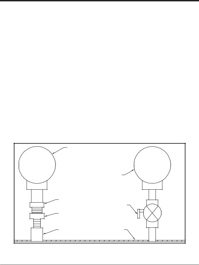
Figure 2 shows a typical mounting arrangement for the pressure and temperature transmitters. The temperature sensor should protrude 1/4 to 1/2 way into the pipe.
Temperature Transmitter |
|
Pressure Transmitter |
|
RTD |
Isolation Valve |
|
|
Thermowell |
|
Coupling |
Flowcell Wall |
Figure 2: Typical Temperature/Pressure Transmitter Mounting
4 |
DigitalFlow™ XGM868i Startup Guide |

Chapter 1. Installation
1.6Mounting the XGM868i Electronics Enclosure
The standard Model XGM868i electronics package is housed in a Type-4X weather-resistant enclosure suitable for indoor or outdoor use. Refer to Figure 8 on page 23 for the mounting dimensions and the weight of this enclosure.
The Model XGM868i electronics enclosure is fitted with a mounting boss that has a single 3/4” NPTF threaded hole at its center and four 1/4-20 tapped holes at its corners. By using this mounting boss, the electronics enclosure may be mounted by any of the typical techniques shown in Figure 10 on page 25.
WARNING! Proper grounding of the XGM868i chassis is required to prevent the possibility of electric shock. See Figure 10 on page 25 for the location of the chassis grounding screw.
IMPORTANT: Since the IREX keys do not work properly in direct sunlight, be sure to position the XGM868i with an optional sunshield or out of direct sunlight.
1.7Making the Electrical Connections
This section contains instructions for making all the necessary electrical connections to the Model XGM868i flow transmitter. Refer to Figure 10 on page 25 for a complete wiring diagram.
Except for the power connector, all electrical connectors are stored on their terminal blocks during shipment and may be removed from the enclosure for more convenient wiring. Simply, feed the cables through the conduit holes on the side of the enclosure, attach the wires to the appropriate connectors and plug the connectors back onto their terminal blocks.
!ATTENTION EUROPEAN CUSTOMERS!
To meet CE Mark requirements, all cables must be installed as described in Appendix A,
CE Mark Compliance.
Refer to Figure 3 on page 6 and prepare the Model XGM868i for wiring by completing the following steps:
DigitalFlow™ XGM868i Startup Guide |
5 |
Chapter 1. Installation
1.7Making the Electrical Connections (cont.)
WARNING! Always disconnect the line power from the Model XGM868i before removing either the front cover or the rear cover. This is especially important in a hazardous environment.
1.Disconnect any existing power line from its source.
2.Loosen the set screw on the rear cover.
3.Place a rod or long screwdriver across the cover in the slots provided, and rotate the cover counterclockwise until it comes free from the enclosure.
4.Install any required cable clamps in the appropriate conduit holes around the side of the enclosure.
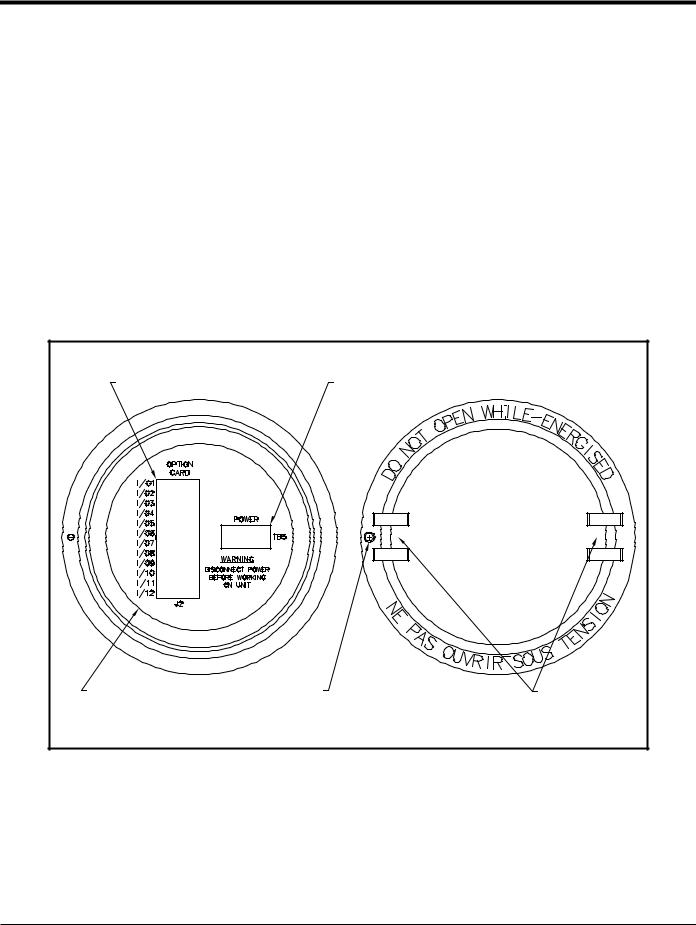
5.Note the labels inside the rear cover to assist in wiring the power and option card connections. Also, Figure 11 on page 26 shows the rear cover option card labels for every available option card configuration.
Proceed to the appropriate section of this chapter to make the desired wiring connections.
Option Card Connections |
Power Connections |
|
Wiring Label |
Set Screw |
Slots |
Inside View |
|
Outside View |
Figure 3: Rear Cover with Connection Labels
6 |
DigitalFlow™ XGM868i Startup Guide |

Chapter 1. Installation
1.7.1 Wiring the Line Power
The Model XGM868i may be ordered for operation with power inputs of 100-120 VAC, 220-240 VAC, or 12-28 VDC. The label on the side of the electronics enclosure lists the meter’s required line voltage and power rating. The fuse size is listed in Chapter 4, Specifications. Be sure to connect the meter only to the specified line voltage.
Note: For compliance with the European Union’s Low Voltage Directive (2006/95/EC), this unit requires an external power disconnect device such as a switch or circuit breaker. The disconnect device must be marked as such, clearly visible, directly accessible, and located within 1.8 m (6 ft) of the Model XGM868i.
Note: Only use Class 2 Rated Power supply for line power connection to DC instrument.
Refer to Figure 10 on page 25 to locate terminal block TB5 and connect the line power as follows:
WARNING! Improper connection of the line power leads or connecting the meter to the incorrect line voltage may damage the unit. It may also result in hazardous voltages at the flowcell and associated piping as well as within the electronics enclosure.
1.Prepare the line power leads by trimming the line and neutral AC power leads (or the positive and negative DC power leads) to a length 0.5 in. (1 cm) shorter than the ground lead. This ensures that the ground lead is the last to detach if the power cable is forcibly disconnected from the meter.
2.Install a suitable cable clamp in the conduit hole indicated in Figure 10 on page 25. If possible, avoid using the other conduit holes for this purpose, to minimize any interference in the circuitry from the AC power line.
!ATTENTION EUROPEAN CUSTOMERS!
To meet CE Mark requirements, all cables must be installed as described in Appendix A,
CE Mark Compliance.
3.Strip 1/4 in. of insulation from the end of each of the three power line leads.
4.Route the cable through the conduit hole and connect the line power leads to terminal block TB5, using the pin number assignments shown in Figure 10 on page 25.
5.Leaving a bit of slack, secure the power line with the cable clamp.
WARNING! Make sure both covers, with their o-ring seals, are installed and the set screws tightened before applying power in a hazardous environment.
CAUTION! The transducers must be properly wired before applying power to the meter.
Proceed to the next section to continue the initial wiring of the Model XGM868i flow transmitter.
DigitalFlow™ XGM868i Startup Guide |
7 |

Chapter 1. Installation
1.7.2 Wiring the Transducers
Before wiring the XGM868i transducers, complete the following steps:
•disconnect the main power from the electronics enclosure
•remove the rear cover and install all required cable clamps
Based on the location of the electronics enclosure, proceed to the appropriate sub-section for detailed instructions.
1.7.2a Flowcell-Mounted Enclosure
For an electronics enclosure mounted directly on the flowcell, wire the transducers as follows:
WARNING! Before connecting the transducers, take them to a safe area and discharge any static buildup by shorting the center conductor of the transducer cables to the metal shield on the cable connector.
Note: For transducer frequencies below 2 MHz, the cable lengths given for a pair of transducers must be within 4 in. (10 cm) of each other. If the transducer frequency exceeds 2 MHz, the cable lengths must be within 0.5 in. (1.25 cm) of each other.
1.Locate the CH1 transducer cables and connect them to the two CH1 transducers in the flowcell. Feed the free ends of the cables through the selected conduit hole in the electronics enclosure.
2.Refer to the wiring diagram in Figure 10 on page 25 and connect the transducer cables to terminal block J3. Then, secure the cable clamp.
Note: The RED cable leads are the SIG(+) leads and the BLACK cable leads are the RTN(-) leads.
!ATTENTION EUROPEAN CUSTOMERS!
To meet CE Mark requirements, all cables must be installed as described in Appendix A,
CE Mark Compliance.
3.For a 2-Channel XGM868i, repeat steps 1-2 to connect the CH2 transducers to terminal block J4. It is not required that both channels of a 2-Channel unit be connected.
4.If wiring of the unit has been completed, reinstall the rear cover on the enclosure and tighten the set screw.
Note: A channel must be activated before it can begin taking measurements. See Chapter 2, Initial Setup, for instructions.
8 |
DigitalFlow™ XGM868i Startup Guide |

Chapter 1. Installation
1.7.2b Remote-Mounted Enclosure
For a remote mounted enclosure, refer to the wiring diagram in Figure 10 on page 25 and the remote transducer wiring in Figure 12 on page 27, and complete the following steps:
WARNING! Before connecting the transducers, take them to a safe area and discharge any static buildup by shorting the center conductor of the transducer cables to the metal shield on the cable connector.
1.Using the pair of coaxial cables with BNC to BNC connectors supplied by the factory (or equivalent cables), connect both CH1 transducers to the preamplifier.
CAUTION! As part of maintaining the FM/CSA environmental rating (TYPE 4) on the remote preamplifier, thread sealant is required on all conduit entries.
2.If an optional lightning protector is being installed, connect it to the preamplifier as shown.
3.Using the supplied coaxial cables with BNC to flying lead connectors (or equivalent cables), route the cables through one of the conduit holes in the electronics enclosure and connect the preamplifier to terminal block J3. Secure the cable clamp.
Note: The RED cable leads are the SIG(+) leads and the BLACK cable leads are the RTN(-) leads.
!ATTENTION EUROPEAN CUSTOMERS!
To meet CE Mark requirements, all cables must be installed as described in Appendix A,
CE Mark Compliance.
4.For a 2-Channel XGM868i, repeat steps 3-5 to connect the CH2 transducers to terminal block J4 in the electronics enclosure. It is not required that both channels of a 2-Channel unit be connected.
5.If wiring of the unit has been completed, reinstall the rear cover on the enclosure and tighten the set screw.
Note: A channel must be activated before it can begin taking measurements. See Chapter 2, Initial Setup, for instructions.
Proceed to the next section to continue the initial wiring of the unit.
DigitalFlow™ XGM868i Startup Guide |
9 |

Chapter 1. Installation
1.7.3 Wiring Std 0/4-20 mA Analog Outputs
The standard configuration of the Model XGM868i flow transmitter includes two isolated 0/4-20 mA analog outputs (designated as outputs 1 and 2). Connections to these outputs may be made with standard twisted-pair wiring, but the current loop impedance for these circuits must not exceed 600 ohms.
To wire the analog outputs, complete the following steps:
1.Disconnect the main power and remove the rear cover.
2.Install the required cable clamp in the chosen conduit hole on the side of the electronics enclosure.
3.Refer to Figure 10 on page 25 for the location of terminal block J1 and wire the analog outputs as shown. Secure the cable clamp.
Note: Analog outputs 1 and 2 in the wiring diagram correspond to analog outputs A and B in Slot 0 in the XGM868i software.
!ATTENTION EUROPEAN CUSTOMERS!
To meet CE Mark requirements, all cables must be installed as described in Appendix A,
CE Mark Compliance.
4. If wiring of the unit has been completed, reinstall the rear cover on the enclosure and tighten the set screw.
WARNING! Make sure both covers, with their o-ring seals, are installed and the set screws tightened before applying power in a hazardous environment.
Note: Prior to use, the analog outputs must be set up and calibrated. See Chapter 1, Calibration, of the Service Manual for detailed instructions.
Proceed to the next section to continue the initial wiring of the unit.
10 |
DigitalFlow™ XGM868i Startup Guide |

Chapter 1. Installation
1.7.4 Wiring the Serial Port
The Model XGM868i flowmeter is equipped with an RS232 or an RS485 serial interface. An RS485 option is also available with MODBUS capability. When the MODBUS option is present, the XGM868i may also have the standard RS232 serial interface.
The serial port is used to transmit stored data and displayed readings to a personal computer by connecting the meter’s serial interface to the serial port of the PC. In addition, the Model XGM868i can receive and execute remote commands, using the Instrument Data Manager or PanaView software via this link.
For more information on serial communications refer to your EIA-RS Serial Communications manual (916-054). Proceed to the appropriate sub-section for wiring instructions.
!ATTENTION EUROPEAN CUSTOMERS!
To meet CE Mark requirements, all cables must be installed as described in Appendix A,
CE Mark Compliance.
1.7.4a Wiring the RS232 Interface
Use the serial port to connect the Model XGM868i flow transmitter to a printer, an ANSI terminal or a personal computer. The RS232 interface is wired as Data Terminal Equipment (DTE). Table 1 lists the standard cables available from the factory for this purpose.
Table 1: GE Serial Cables
Part Number |
PC Connector |
XGM868i Connector |
|
|
|
704-659 |
DB-25 Male |
Flying Leads (5) |
|
|
|
704-660 |
DB-9 Male |
Flying Leads (5) |
|
|
|
704-661 |
DB-25 Female |
Flying Leads (5) |
|
|
|
704-662 |
DB-9 Female |
Flying Leads (5) |
|
|
|
Each of the cables listed in the table above is available in several standard lengths. However, a user-supplied cable may be used, if preferred. In either case, wire the XGM868i end of the serial cable in accordance with the pin designations listed in Table 2 on page 12.
DigitalFlow™ XGM868i Startup Guide |
11 |

Chapter 1. Installation
1.7.4a Wiring the RS232 Interface (cont.)
Refer to Figure 10 on page 25 to complete the following steps:
WARNING! Dangerous voltages exist within the electronics enclosure. Do not attempt to wire the unit until the main power has been disconnected
1. Disconnect the main power and remove the rear cover.
WARNING! The XGM868i must be moved to a safe environment before removing either cover.
2.Install the required cable clamp in the chosen conduit hole on the side of the electronics enclosure.
3.Use the information in Table 2 to construct a suitable cable for connecting the Model XGM868i to the external device. If desired, an appropriate cable may be purchased from the factory.
Table 2: RS232 Connection to DCE or DTE Device
|
|
DCE |
DCE |
DTE |
DTE |
|
J1 |
Signal |
DB25 |
DB9 |
DB25 |
DB9 |
|
Pin # |
Description |
Pin # |
Pin # |
Pin # |
Pin # |
|
|
|
|
|
|
|
|
5 |
DTR (Data Terminal |
20 |
4 |
20 |
4 |
|
Ready) |
||||||
|
|
|
|
|
||
|
|
|
|
|
|
|
6 |
CTS (Clear to Send) |
4 |
7 |
5 |
8 |
|
|
|
|
|
|
|
|
7 |
COM (Ground) |
7 |
5 |
7 |
5 |
|
|
|
|
|
|
|
|
8 |
RX (Receive) |
2 |
3 |
3 |
2 |
|
|
|
|
|
|
|
|
9 |
TX (Transmit) |
3 |
2 |
2 |
3 |
|
|
|
|
|
|
|
4.Feed the cable’s flying leads through the conduit hole and wire it to terminal block J1. Connect the other end of the cable to the external serial device and secure the cable clamp.
After the wiring has been completed, consult the User’s Manual for the external device to configure it for use with the XGM868i.
12 |
DigitalFlow™ XGM868i Startup Guide |
Chapter 1. Installation
1.7.4b Wiring the RS485 Interface
Use the optional RS485 serial port to network multiple XGM868i flow transmitters to a single control system. As an option, the standard RS232 port on the XGM868i may be configured as a
two-wire, half-duplex RS485 interface.
IMPORTANT: The Model XGM868i must be configured at the factory for RS485 operation.
To wire the RS485 serial port, refer to Figure 10 on page 25 and complete the following steps:
WARNING! Dangerous voltages exist within the electronics enclosure. Do not attempt to wire the unit until the main power has been disconnected
1. Disconnect the main power and remove the rear cover.
WARNING! The XGM868i must be moved to a safe environment before removing either cover.
2.Install the required cable clamp in the chosen conduit hole on the side of the electronics enclosure.
3.Feed one end of the cable through the conduit hole, wire it to terminal block J1 and secure the cable clamp. Use the information in Table 3 to wire a suitable cable for connecting the XGM868i to the external device.
Table 3: RS485 Connections
J1 Pin # |
Signal Description |
|
|
9 |
Data + |
|
|
8 |
Data - |
|
|
7 |
Shield |
|
|
6 |
Not Used |
|
|
5 |
Not Used |
|
|
4 |
Not Used |
|
|
4. If wiring of the unit has been completed, reinstall the rear cover on the enclosure and tighten the set screw. Proceed to the next section to continue the initial wiring of the unit.
DigitalFlow™ XGM868i Startup Guide |
13 |

Chapter 1. Installation
1.7.5 Wiring the Option Cards
The Model XGM868i can accommodate one option card in Slot 1 and one option card in Slot 2. The following option card functions are available only in the combinations listed in Table 14 on page 63:
•
•
•
•
•
•
•
•
•
•
Alarm Relays (Slot 1)
Analog Inputs (Slot 1)
Totalizer/Frequency Outputs (Slot 1)
RTD Inputs (Slot 1)
Analog Outputs (Slot 1)
MODBUS Communications (Slot 2)
MODBUS/TCP Communications (Slot 2)
Ethernet (Slot 2)
Foundation Fieldbus (Slot 2)
Data Logging (Slot 2) - no wiring required
Wiring any option card installed in Slot 1 requires completion of the following general steps:
1.7.5a Preparing for Wiring
1.Disconnect the main power and remove the rear cover.
2.Install a cable clamp in the chosen conduit hole on the side of the electronics enclosure and feed a standard twisted-pair cable through this conduit hole.
3.Locate the 12-pin terminal block (J2) in Figure 10 on page 25 and wire the option card as indicated on the label inside the rear cover (see Figure 3 on page 6 and Figure 11 on page 26). Secure the cable clamp.
IMPORTANT: Because of the attached wiring label, all rear covers must remain with their original meters.
!ATTENTION EUROPEAN CUSTOMERS!
To meet CE Mark requirements, all cables must be installed as described in Appendix A,
CE Mark Compliance.
4. If wiring of the unit has been completed, reinstall the rear cover on the enclosure and tighten the set screw.
Note: Prior to use, the option card must be set up and calibrated. See Chapter 1, Programming Site Data, in the Programming Manual and Chapter 1, Calibration, in the Service Manual for detailed instructions.
For more specific instructions on particular option cards, proceed to the appropriate section(s) that follow.
14 |
DigitalFlow™ XGM868i Startup Guide |
Chapter 1. Installation
1.7.5b Wiring an Alarms Option Card
Each alarms option card includes two or four general-purpose Form C relays (designated as A, B, C and D).
The maximum electrical ratings for the relays are listed in Chapter 4, Specifications. Each of the alarm relays can be wired as either Normally Open (NO) or Normally Closed (NC).
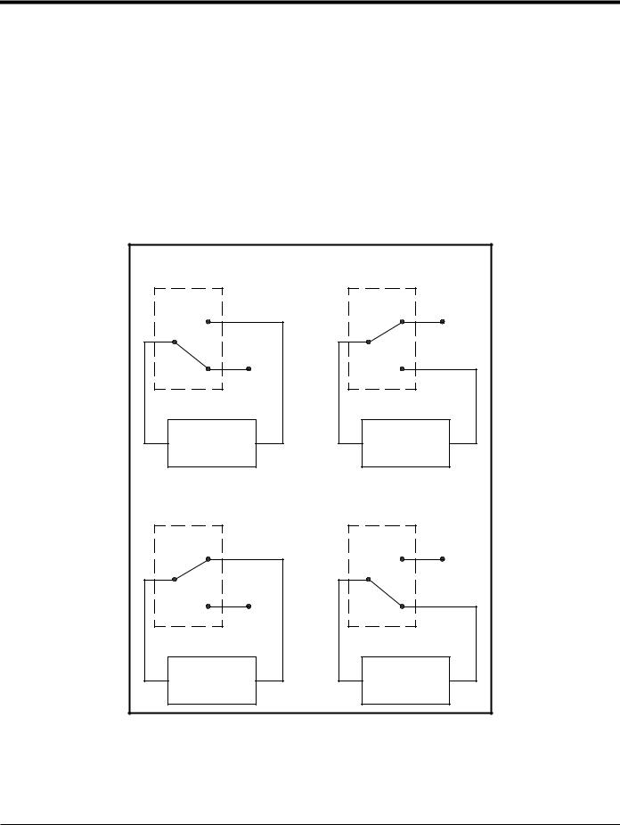
In setting up an alarm relay, it may be wired for either conventional or fail-safe operation. In fail-safe mode, the alarm relay is constantly energized, except when it is triggered or a power failure or other interruption occurs. See Figure 4 for the operation of a NO alarm relay in both conventional and fail-safe mode.
Before making any connections, complete the steps in Preparing for Wiring on page 14. Connect each alarm relay in accordance with the wiring instructions shown on the label inside the rear cover (see Figure 3 on page 6 and Figure 11 on page 26).
Conventional, |
Fail-Safe, |
not triggered |
not triggered |
NO |
NO |
C |
C |
NC |
NC |
Alarm |
Alarm |
Monitoring |
Monitoring |
Device |
Device |
Conventional, |
Fail-Safe, |
triggered |
triggered or power failure |
NO |
NO |
C |
C |
NC |
NC |
Alarm |
Alarm |
Monitoring |
Monitoring |
Device |
Device |
Figure 4: Conventional and Fail-Safe Operation
DigitalFlow™ XGM868i Startup Guide |
15 |
Chapter 1. Installation
1.7.5c Wiring a 0/4-20 mA Analog Inputs Option Card
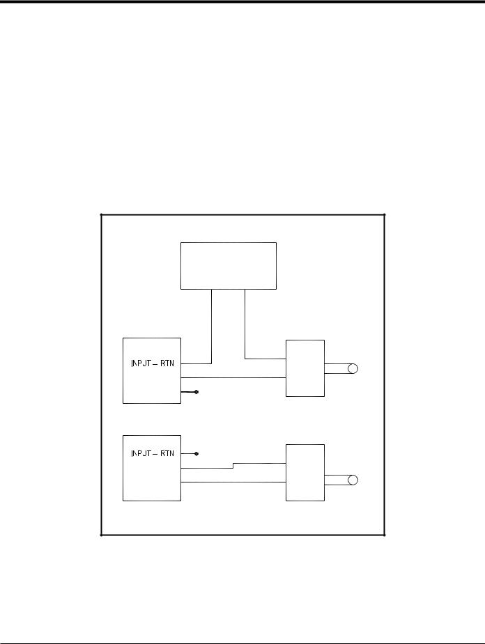
To calculate the standard flow rates, the Model XGM868i requires accurate temperature and pressure data from the measurement site. Transmitters installed in the flowcell can provide this information via an optional 0/4-20 mA analog inputs option card. This option card includes two or four isolated 0/4-20 mA analog inputs (designated as A, B, C and D), each of which includes a 24 VDC power supply for loop-powered transmitters. Either input may be used to process the temperature signal, while the other input is used to process the pressure signal.
Note: To properly enter programming data into the meter, it is necessary to know which input is assigned to which process parameter. This information should be entered in Appendix B, Data Records.
The analog inputs, which have an impedance of 118 ohms, should be connected with standard twisted-pair wiring. Power to the transmitters may be supplied either by the integral 24 VDC power supply on the analog input option card or by an external power supply. Figure 5 shows typical wiring diagrams, with and without an external power supply, for one of the analog inputs.
With External Power Supply |
|
|
24 VDC |
|
|
POWER SUPPLY |
|
|
– |
+ |
|
Analog Input |
Transmitter |
|
|
+ IN |
Sensor |
|
|
|
INPUT + |
– OUT |
|
+24V |
|
|
Analog Input |
Transmitter |
|
|
|
|
INPUT + |
– OUT |
Sensor |
|
||
+24V |
+ IN |
|
With Internal Power Supply |
|
|
Figure 5: Analog Input Wiring Diagram
16 |
DigitalFlow™ XGM868i Startup Guide |
Chapter 1. Installation
1.7.5c Wiring a 0/4-20 mA Analog Inputs Option Card (cont.)
Before making any connections, complete the steps in Preparing for Wiring on page 14. Wire the analog inputs as shown on the label in the rear cover (see Figure 11 on page 26).
Note: The analog inputs option card can be calibrated with the Model XGM868i’s built-in analog outputs. However, be certain that the analog outputs have been calibrated first. See Chapter 1, Calibration, in the Service Manual for the appropriate procedures.
1.7.5d Wiring a Totalizer/Frequency Outputs Option Card
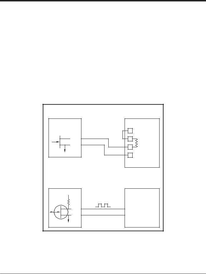
Each totalizer/frequency outputs option card provides two or four outputs (designated as A, B, C, and D) that can be used as either totalizer or frequency outputs.
Before making any connections, complete the steps in Preparing for Wiring on page 14. Then, wire this option card in accordance with the connections shown on the label in the rear cover (see Figure 3 on page 6 and Figure 11 on
page 26). Figure 6 shows sample wiring diagrams of a totalizer output circuit and a frequency output circuit. Refer to Electrical Specifications on page 56 for load and voltage requirements.
|
Totalizer Output |
|
Transmitter |
Pulse Counter |
|
|
Volts + |
|
|
(Int. Pwr. Sup.) |
|
OUT |
Load |
|
RTN |
||
|
||
|
Volts – |
|
|
(Common) |
|
|
Frequency Output |
|
Transmitter |
Frequency Counter |
|
+5V |
|
|
200: |
|
|
OUT |
IN |
|
RTN |
Common |
Figure 6: Totalizer/Frequency Outputs Wiring
DigitalFlow™ XGM868i Startup Guide |
17 |

Chapter 1. Installation
1.7.5e Wiring an RTD Inputs Option Card
The Model XGM868i RTD (Resistance Temperature Device) inputs option card provides two or four direct RTD inputs (designated as A, B, C and D). Each RTD input requires three wires, and should be connected as shown on the label in the rear cover (see Figure 3 on page 6 and Figure 11 on page 26).
Note: Before making any connections, complete the steps in Preparing for Wiring on page 14.
1.7.5f Wiring a 0/4-20 mA Analog Outputs Option Card
The analog outputs option card includes two isolated 0/4-20 mA outputs (designated as A and B). Connections to these outputs may be made with standard twisted-pair wiring, but the total current loop impedance for these circuits must not exceed 1,000 ohms.
Before making any connections, complete the steps in Preparing for Wiring on page 14. Then, wire this option card with the connections shown on the label in the rear cover (see Figure 3 on page 6 and Figure 11 on page 26).
1.7.5g A Specific Example
To illustrate the procedures described in the previous sections for wiring the option cards, a specific example may prove helpful. Assume that a Model XGM868i is equipped with an option card numbered 703-1223-08. Table 14 on page 63 in Appendix B, Data Records, indicates that this option card includes two analog current inputs and two standard alarm relays.
By referring to Figure 11 on page 26, it is determined that the appropriate connection diagram for this option card is the second one from the left in the middle row (AI,HI). This label should also be found inside the rear cover of the XGM868i. Based on this information, wiring of the Input/Output connections to terminal block J2 should be completed as shown in Table 4.
Table 4: Wiring a 703-1223-08 Option Card
J2 Pin # |
Description |
Connection |
|
|
|
1 |
Alarm A |
Normally Open |
|
|
|
2 |
Alarm A |
Common |
|
|
|
3 |
Alarm A |
Normally Closed |
|
|
|
4 |
Alarm B |
Normally Open |
|
|
|
5 |
Alarm B |
Common |
|
|
|
6 |
Alarm B |
Normally Closed |
|
|
|
7 |
Out C |
+24 V to Input C |
|
|
|
8 |
Input C |
Signal (+) |
|
|
|
9 |
Input C |
Return (-) |
|
|
|
10 |
Out D |
+24 V to Input D |
|
|
|
11 |
Input D |
Signal (+) |
|
|
|
12 |
Input D |
Return (-) |
|
|
|
18 |
DigitalFlow™ XGM868i Startup Guide |

Chapter 1. Installation
1.7.5h Wiring the MODBUS Option Card
The MODBUS option card uses the RS485 standard for MODBUS communication. The MODBUS card must be installed in Slot 2. The RS485 standard allows up to 32 nodes (drivers and receivers) on one multidrop network, at distances up to 4,000 ft (1,200 m). GE recommends using 24-gauge (24 AWG) twisted-pair wire with a characteristic impedance of 120 ohms and 120-ohm termination at each end of the communications line.
Note: The MODBUS option card provides its own RS485 connections. Thus, the meter can have its serial port configured as RS232 and still provide RS485 MODBUS signals.
IMPORTANT: Because the MODBUS option card uses pins 1 and 2 on terminal block J2, only those option cards that do not use these pins may be installed in Slot 1, while a MODBUS card is installed in Slot 2. Specifically, only the option cards designated as “OI” and “OR” in Figure 11 on page 26 are compatible with the MODBUS option card.
To link the XGM868i to the control system (refer to Figure 7):
1.Connect the MODBUS – wire to pin #2, the inverting or negative connection.
2.Connect the MODBUS + wire to pin #1, the non-inverting or positive connection.
3.Pin #3 has no connection.
.
MODBUS +
MODBUS – 


N/C
Figure 7: The RS485 MODBUS Terminal Block Connector
DigitalFlow™ XGM868i Startup Guide |
19 |

Chapter 1. Installation
1.7.5i Wiring the MODBUS/TCP Interface
Customers can also use a modified XGM868i that provides a MODBUS/TCP interface to communicate to an internal network. An optional MODBUS/TCP card with a unique MAC (IP) address (installed only in slot 2) includes an RJ45 connector. To connect the MODBUS/TCP-enabled XGM868i to the network, insert the jack of an RJ45 cable into the RJ45 connector, route the cable through one of the conduit holes using an appropriate cable clamp, and wire the other end of the cable to the Ethernet network according to the manufacturer’s instructions. See Figure 13 on page 28.
Note: The MAC address for a specific XGM868i is included with customer documentation. For more information on setting up the MAC address, refer to Chapter 6 of the Programming Manual.
1.7.5j Wiring the Ethernet Interface
A modified XGM868i can use the Ethernet interface to communicate to a local area network. An optional Ethernet card with a unique MAC (IP) address (installed only in slot 2) includes an RJ45 connector. To connect the Ethernet-enabled XGM868i to the network, insert the jack of an RJ45 cable into the RJ45 connector, route the cable through one of the conduit holes using an appropriate cable clamp, and wire the other end of the cable to the Ethernet network according to the manufacturer’s instructions. An external connection is required between the Ethernet option card and the XGM868i’s RS232 connector, as shown in Table 5 and Figure 13 on page 28.
Note: The MAC address for a specific XGM868i is included with customer documentation. For more information on setting up the MAC address, refer to Appendix C of the Programming Manual.
Table 5: RS232 to Ethernet Interconnections
XGM868i Type |
Terminal Block |
Terminal Block |
|
|
|
|
RS232 on Rear |
TB1 on Ethernet |
Terminal |
Board |
Card |
|
|
|
|
TX |
Pin 1 |
|
|
|
|
RX |
Pin 2 |
|
|
|
|
COM |
Pin 3 |
|
|
|
20 |
DigitalFlow™ XGM868i Startup Guide |
Loading...