

Page 1
7210 Server
System Manual
Page 2

Contents
Preface. . . . . . . . . . . . . . . . . . . . . . . . . . . . . . . . . . . . . . . . . . . . . . . . . . . . . . . . . . . . . . v
Conventions used in this manual . . . . . . . . . . . . . . . . . . . . . . . . . . . . . . . . . . . . . . . v
Getting additional information . . . . . . . . . . . . . . . . . . . . . . . . . . . . . . . . . . . . . . . . . . vi
1 System Features . . . . . . . . . . . . . . . . . . . . . . . . . . . . . . . . . . . . . . . . . . . . . . . . 1
Standard features . . . . . . . . . . . . . . . . . . . . . . . . . . . . . . . . . . . . . . . . . . . . . . . . . . . 1
Front panel . . . . . . . . . . . . . . . . . . . . . . . . . . . . . . . . . . . . . . . . . . . . . . . . . . . . . . . . 2
Back panel . . . . . . . . . . . . . . . . . . . . . . . . . . . . . . . . . . . . . . . . . . . . . . . . . . . . . . . . . 4
Interior of system . . . . . . . . . . . . . . . . . . . . . . . . . . . . . . . . . . . . . . . . . . . . . . . . . . . . 6
System board . . . . . . . . . . . . . . . . . . . . . . . . . . . . . . . . . . . . . . . . . . . . . . . . . . . . . . 8
Hot-plug backplane . . . . . . . . . . . . . . . . . . . . . . . . . . . . . . . . . . . . . . . . . . . . . . . . . 11
Front panel board . . . . . . . . . . . . . . . . . . . . . . . . . . . . . . . . . . . . . . . . . . . . . . . . . . 13
2 System Setup . . . . . . . . . . . . . . . . . . . . . . . . . . . . . . . . . . . . . . . . . . . . . . . . . . 15
Setting up the server . . . . . . . . . . . . . . . . . . . . . . . . . . . . . . . . . . . . . . . . . . . . . . . . 15
Installing the outriggers and castors . . . . . . . . . . . . . . . . . . . . . . . . . . . . . . . . . . . . 16
Starting the server . . . . . . . . . . . . . . . . . . . . . . . . . . . . . . . . . . . . . . . . . . . . . . . . . . 17
Understanding the Power-On Self-Test . . . . . . . . . . . . . . . . . . . . . . . . . . . . . . 18
Setting up the operating system . . . . . . . . . . . . . . . . . . . . . . . . . . . . . . . . . . . . 18
Turning off the server . . . . . . . . . . . . . . . . . . . . . . . . . . . . . . . . . . . . . . . . . . . . . . . 19
Resetting the server . . . . . . . . . . . . . . . . . . . . . . . . . . . . . . . . . . . . . . . . . . . . . . . . 20
3 Case Access . . . . . . . . . . . . . . . . . . . . . . . . . . . . . . . . . . . . . . . . . . . . . . . . . . . 21
Preventing static electricity discharge . . . . . . . . . . . . . . . . . . . . . . . . . . . . . . . . . . . 22
Opening the case . . . . . . . . . . . . . . . . . . . . . . . . . . . . . . . . . . . . . . . . . . . . . . . . . . 23
Opening the bezel door . . . . . . . . . . . . . . . . . . . . . . . . . . . . . . . . . . . . . . . . . . 24
Removing the front bezel . . . . . . . . . . . . . . . . . . . . . . . . . . . . . . . . . . . . . . . . . 25
Removing the side panel . . . . . . . . . . . . . . . . . . . . . . . . . . . . . . . . . . . . . . . . . 26
Closing the case . . . . . . . . . . . . . . . . . . . . . . . . . . . . . . . . . . . . . . . . . . . . . . . . . . . 27
Replacing the side panel . . . . . . . . . . . . . . . . . . . . . . . . . . . . . . . . . . . . . . . . . 27
Replacing the front bezel . . . . . . . . . . . . . . . . . . . . . . . . . . . . . . . . . . . . . . . . . 29
Closing the bezel door . . . . . . . . . . . . . . . . . . . . . . . . . . . . . . . . . . . . . . . . . . . 30
4 Replacing and Adding Internal Devices . . . . . . . . . . . . . . . . . . . . . . . . 31
Drives . . . . . . . . . . . . . . . . . . . . . . . . . . . . . . . . . . . . . . . . . . . . . . . . . . . . . . . . . . . . 32
Preparing to replace or add a drive . . . . . . . . . . . . . . . . . . . . . . . . . . . . . . . . . 32
Drive cabling information . . . . . . . . . . . . . . . . . . . . . . . . . . . . . . . . . . . . . . . . . 33
Replacing the diskette drive . . . . . . . . . . . . . . . . . . . . . . . . . . . . . . . . . . . . . . . 33
i
Page 3

Replacing the optional boot drive . . . . . . . . . . . . . . . . . . . . . . . . . . . . . . . . . . .35
Replacing a hot-plug drive . . . . . . . . . . . . . . . . . . . . . . . . . . . . . . . . . . . . . . . . .37
Adding a hot-plug drive . . . . . . . . . . . . . . . . . . . . . . . . . . . . . . . . . . . . . . . . . . .41
Replacing the CD drive . . . . . . . . . . . . . . . . . . . . . . . . . . . . . . . . . . . . . . . . . . .46
Adding additional 5.25-inch devices . . . . . . . . . . . . . . . . . . . . . . . . . . . . . . . . .48
Memory . . . . . . . . . . . . . . . . . . . . . . . . . . . . . . . . . . . . . . . . . . . . . . . . . . . . . . . . . . .50
Replacing memory . . . . . . . . . . . . . . . . . . . . . . . . . . . . . . . . . . . . . . . . . . . . . . .50
Adding memory . . . . . . . . . . . . . . . . . . . . . . . . . . . . . . . . . . . . . . . . . . . . . . . . .52
Processors . . . . . . . . . . . . . . . . . . . . . . . . . . . . . . . . . . . . . . . . . . . . . . . . . . . . . . . .53
Replacing a processor . . . . . . . . . . . . . . . . . . . . . . . . . . . . . . . . . . . . . . . . . . . .53
Adding a processor . . . . . . . . . . . . . . . . . . . . . . . . . . . . . . . . . . . . . . . . . . . . . .56
Replacing the battery . . . . . . . . . . . . . . . . . . . . . . . . . . . . . . . . . . . . . . . . . . . . . . . .58
Expansion cards . . . . . . . . . . . . . . . . . . . . . . . . . . . . . . . . . . . . . . . . . . . . . . . . . . . .61
Replacing an expansion card . . . . . . . . . . . . . . . . . . . . . . . . . . . . . . . . . . . . . .61
Adding an expansion card . . . . . . . . . . . . . . . . . . . . . . . . . . . . . . . . . . . . . . . . .63
Power supplies . . . . . . . . . . . . . . . . . . . . . . . . . . . . . . . . . . . . . . . . . . . . . . . . . . . . .65
Replacing a redundant power supply module . . . . . . . . . . . . . . . . . . . . . . . . . .65
Replacing the redundant power supply . . . . . . . . . . . . . . . . . . . . . . . . . . . . . . .67
Replacing the PS/2 power supply . . . . . . . . . . . . . . . . . . . . . . . . . . . . . . . . . . .70
Replacing the back panel and hot-plug cage fans . . . . . . . . . . . . . . . . . . . . . . . . .72
Replacing the control panel board . . . . . . . . . . . . . . . . . . . . . . . . . . . . . . . . . . . . . .74
Replacing the hot-plug backplane . . . . . . . . . . . . . . . . . . . . . . . . . . . . . . . . . . . . . .75
Replacing the system board . . . . . . . . . . . . . . . . . . . . . . . . . . . . . . . . . . . . . . . . . . .78
5 Using the BIOS Setup Utility . . . . . . . . . . . . . . . . . . . . . . . . . . . . . . . . . . . .83
About the BIOS Setup utility . . . . . . . . . . . . . . . . . . . . . . . . . . . . . . . . . . . . . . . . . . .83
Updating the BIOS . . . . . . . . . . . . . . . . . . . . . . . . . . . . . . . . . . . . . . . . . . . . . . . . . .85
Setting the system board jumpers . . . . . . . . . . . . . . . . . . . . . . . . . . . . . . . . . . . . . .86
The CMOS Clear jumper . . . . . . . . . . . . . . . . . . . . . . . . . . . . . . . . . . . . . . . . . .86
Password Clear jumper . . . . . . . . . . . . . . . . . . . . . . . . . . . . . . . . . . . . . . . . . . .86
Recovery Boot jumper . . . . . . . . . . . . . . . . . . . . . . . . . . . . . . . . . . . . . . . . . . . .87
BIOS Boot Block Write Enable jumper . . . . . . . . . . . . . . . . . . . . . . . . . . . . . . .88
BMC Boot Block Write Enable jumper . . . . . . . . . . . . . . . . . . . . . . . . . . . . . . . .88
FRB Enable jumper . . . . . . . . . . . . . . . . . . . . . . . . . . . . . . . . . . . . . . . . . . . . . .89
Intrusion Detection Enable jumper . . . . . . . . . . . . . . . . . . . . . . . . . . . . . . . . . . .90
BMC Firmware Update jumper . . . . . . . . . . . . . . . . . . . . . . . . . . . . . . . . . . . . .90
WOL Enable jumper . . . . . . . . . . . . . . . . . . . . . . . . . . . . . . . . . . . . . . . . . . . . . .91
6 Managing the Server . . . . . . . . . . . . . . . . . . . . . . . . . . . . . . . . . . . . . . . . . . . .93
Avoiding power source problems . . . . . . . . . . . . . . . . . . . . . . . . . . . . . . . . . . . . . . .93
Surge suppressors . . . . . . . . . . . . . . . . . . . . . . . . . . . . . . . . . . . . . . . . . . . . . . .93
Line conditioners . . . . . . . . . . . . . . . . . . . . . . . . . . . . . . . . . . . . . . . . . . . . . . . .94
Uninterruptible power supplies . . . . . . . . . . . . . . . . . . . . . . . . . . . . . . . . . . . . . .94
ii
Page 4

Maintain and manage your hard drive . . . . . . . . . . . . . . . . . . . . . . . . . . . . . . . . . . 94
Hard drive maintenance utility . . . . . . . . . . . . . . . . . . . . . . . . . . . . . . . . . . . . . 94
Hard drive management practices . . . . . . . . . . . . . . . . . . . . . . . . . . . . . . . . . . 95
Protecting the server against viruses . . . . . . . . . . . . . . . . . . . . . . . . . . . . . . . . . . . 98
System administration and control . . . . . . . . . . . . . . . . . . . . . . . . . . . . . . . . . . . . . 99
Intel Server Control (ISC) . . . . . . . . . . . . . . . . . . . . . . . . . . . . . . . . . . . . . . . . . 99
ManageX Event Manager . . . . . . . . . . . . . . . . . . . . . . . . . . . . . . . . . . . . . . . . . 99
Direct Platform Control (DPC) Console . . . . . . . . . . . . . . . . . . . . . . . . . . . . . 100
System security . . . . . . . . . . . . . . . . . . . . . . . . . . . . . . . . . . . . . . . . . . . . . . . . 100
System recovery . . . . . . . . . . . . . . . . . . . . . . . . . . . . . . . . . . . . . . . . . . . . . . . . . . 104
Creating a startup diskette . . . . . . . . . . . . . . . . . . . . . . . . . . . . . . . . . . . . . . . 104
Using your Server Companion CD . . . . . . . . . . . . . . . . . . . . . . . . . . . . . . . . . 104
7 Troubleshooting . . . . . . . . . . . . . . . . . . . . . . . . . . . . . . . . . . . . . . . . . . . . . . . 105
Introduction . . . . . . . . . . . . . . . . . . . . . . . . . . . . . . . . . . . . . . . . . . . . . . . . . . . . . . 105
Troubleshooting checklist . . . . . . . . . . . . . . . . . . . . . . . . . . . . . . . . . . . . . . . . . . . 105
Verifying your configuration . . . . . . . . . . . . . . . . . . . . . . . . . . . . . . . . . . . . . . 105
Troubleshooting guidelines . . . . . . . . . . . . . . . . . . . . . . . . . . . . . . . . . . . . . . . 106
CD problems . . . . . . . . . . . . . . . . . . . . . . . . . . . . . . . . . . . . . . . . . . . . . . . . . . . . . 106
Hard drive problems . . . . . . . . . . . . . . . . . . . . . . . . . . . . . . . . . . . . . . . . . . . . . . . 108
Memory and processor problems . . . . . . . . . . . . . . . . . . . . . . . . . . . . . . . . . . . . . 109
Modem problems . . . . . . . . . . . . . . . . . . . . . . . . . . . . . . . . . . . . . . . . . . . . . . . . . . 110
Peripheral/Adapter problems . . . . . . . . . . . . . . . . . . . . . . . . . . . . . . . . . . . . . . . . . 110
Printer problems . . . . . . . . . . . . . . . . . . . . . . . . . . . . . . . . . . . . . . . . . . . . . . . . . . 112
System problems . . . . . . . . . . . . . . . . . . . . . . . . . . . . . . . . . . . . . . . . . . . . . . . . . . 113
Video problems . . . . . . . . . . . . . . . . . . . . . . . . . . . . . . . . . . . . . . . . . . . . . . . . . . . 115
Error messages . . . . . . . . . . . . . . . . . . . . . . . . . . . . . . . . . . . . . . . . . . . . . . . . . . . 118
A Safety, Regulatory, and Notices . . . . . . . . . . . . . . . . . . . . . . . . . . . . . . . 123
B System Specifications . . . . . . . . . . . . . . . . . . . . . . . . . . . . . . . . . . . . . . . . 133
Environmental specifications . . . . . . . . . . . . . . . . . . . . . . . . . . . . . . . . . . . . . . . . . 134
System I/O addresses . . . . . . . . . . . . . . . . . . . . . . . . . . . . . . . . . . . . . . . . . . . . . . 134
Memory map . . . . . . . . . . . . . . . . . . . . . . . . . . . . . . . . . . . . . . . . . . . . . . . . . . . . . 138
Interrupts . . . . . . . . . . . . . . . . . . . . . . . . . . . . . . . . . . . . . . . . . . . . . . . . . . . . . . . . 138
DMA usage . . . . . . . . . . . . . . . . . . . . . . . . . . . . . . . . . . . . . . . . . . . . . . . . . . . . . . 139
Index. . . . . . . . . . . . . . . . . . . . . . . . . . . . . . . . . . . . . . . . . . . . . . . . . . . . . . . . . . . . . . 141
iii
Page 5

iv
Page 6
Preface
Conventions used in this manual
Throughout this manual, you will see the following conventions:
Convention Description
ENTER Keyboard key names are printed in small capitals.
C
TRL+ALT+DEL A plus sign means to press the keys at the same time.
Setup Commands to be entered, options to select, and messages that
appear on your monitor are printed in bold.
User’s Guide Names of publications are printed in italic.
Viewpoint All references to front, rear, left, or right on the co mp uter are based
on the computer bein g in a norma l, upri ght pos ition , as v iewed fr om
the front.
Important A note labeled important informs you of special
circumstances.
Caution A caution warns you of possible damage to equipment or
loss of data.
Warning A warning indicates the possibility of personal injury.
Conventions used in this manual v
Page 7

Getting additional information
Log on to the Gateway technical support at www .gateway .com/suppo rt to find
information about your system or other Gateway products. Some types of
information you can access are:
■ Hardware driver and program u pdates
■ Technical tips
■ Service agreement information
■ Technical documents and component info rmation
■ Frequently asked questions (FAQs)
■ Documentation for per ipherals or optional co mponents
■ Online technical support
vi Preface
Page 8

System Features
Standard features
■ As many as two Intel
Bus (FSB) in Slot 1 processor sockets
■ Four Dual Inline Memory Module (DIMM) sockets, that support up to
2.0 GB of PC100 Synchronous Dynamic Random Access Memory
(SDRAM).
■ Intel 440GX chipset
■ Integrated Intel 82559 network controller providing 10/100 LAN support
■ Integrated Super Vector Graphics Array (SVGA) video support with 2 MB
of Synchronous Graphics RAM (SGRAM)
■ Six PCI slots and one ISA slot for expansion cards
■ ATX form factor system board and convertible tower/rack-mount chassis
■ One 3.5 inch 1.44 MB diskette drive, one CD drive , and at lea st one ha rd
drive
■ Integrated voltage regulator modules (VRMs) for both processors
■ Integrated Adaptec AIC 7896 dual function controller providing both
low-voltage differential (LVD) Ultra2 small computer systems interface
(SCSI) and Ultra Wide single-ended (SE) SCSI supp ort
®
Pentium III processors with 100 MHz Front Side
1
■ Six drive ho t-plug cag e
■ Keyboard port (PS/2), mouse port (PS/2), two serial ports, parallel port,
video port, RJ-45 LAN port, and two Universa l Serial Bus (USB) ports
Standard features 1
Page 9
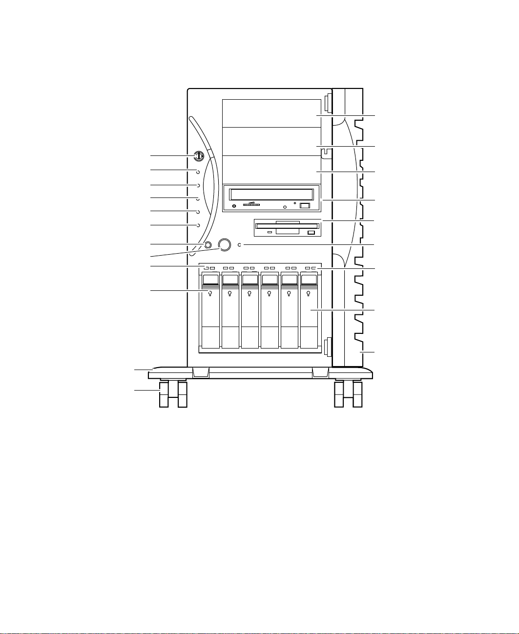
Front panel
5.25” drive bay
Chassis lock
Power LED
Disk activity LED
Reserved LED
PS 1 status LED
PS 2 status LED
Reset button
Power button
Reserved
Hot-plug drive lock
Outriggers
Castors
5.25” drive bay
5.25” drive bay
CD drive
Diskette drive
Power supply
alarm speake r
reset
Hot-plug drive
activity LED
Hot-plug
drive bay
Front panel door
Chassis lock that prevents unauthorized access to both the front panel
controls and to the interior of the system by locking the front bezel onto the
chassis.
Power LED that glows green whenever the system is turned on. The LED also
flashes when the system is in sleep mode.
Disk activity LED that glows green whenever any of the hard disks is actively
reading or writing data.
Reserved LED this LED is reserved for future use.
2 System Features
Page 10

PS1 status LED that glows green when the first powe r supply mod ule in the
redundant power supply is installed and working correctly. It flashes green if
the power supply module fails or one of its power levels goes out of bounds.
If the power supply module is not installed, this LED is off. The LED is only
active on systems using the Redundant N+1 power supply.
PS2 status LED that glows green when the second power supply module in
the redundant power supply is installed and working correctly . It flashes green
if the power supply module fails or one of its power levels goes out of bounds.
If the power supply module is not installed, this LED is off. The LED is only
active on systems using the Redundant N+1 power supply.
System reset button is a recessed button that lets you reset the server if it
has become nonresponsive.
Power button turns the ser ver on and off. In an ACPI-enabled operatin g
system like Windows 2000, you can set the power button to enter sleep mode
rather than turning the system off.
Reserved LEDs these LEDs are reserved for future use.
Hot-plug driv e lock secures the drive in place to prevent unauthorized or
accidental removal.
The outriggers provide support for the castors.
Castors let you roll the server around for ease of service.
5.25-inch drive bays ( 3) to let you install additional 5.25-inch devices such
as tape drives or an additio nal CD drive.
CD drive plays data or audio CDs
Diskette d rive writes to and reads from 3.5-inch, 1.44 MB diskettes.
Power alarm speaker reset disables the power supply alarm speaker. The
alarm is not cleared and the appropriate LED continues to fla sh until the failed
power supply module is replaced. The alarm is only active on systems using
the N+1 redundant power supply.
Hot-plug drive activity LED that indicates when the hot-plug drive
immediately below it is reading or writing data.
Hot-plug driv es up to six hot-swappable hot-plug drives connected to a
hot-plug backplane.
Front panel door covers the front panel controls to prevent unauthorized or
accidental access.
Front panel 3
Page 11
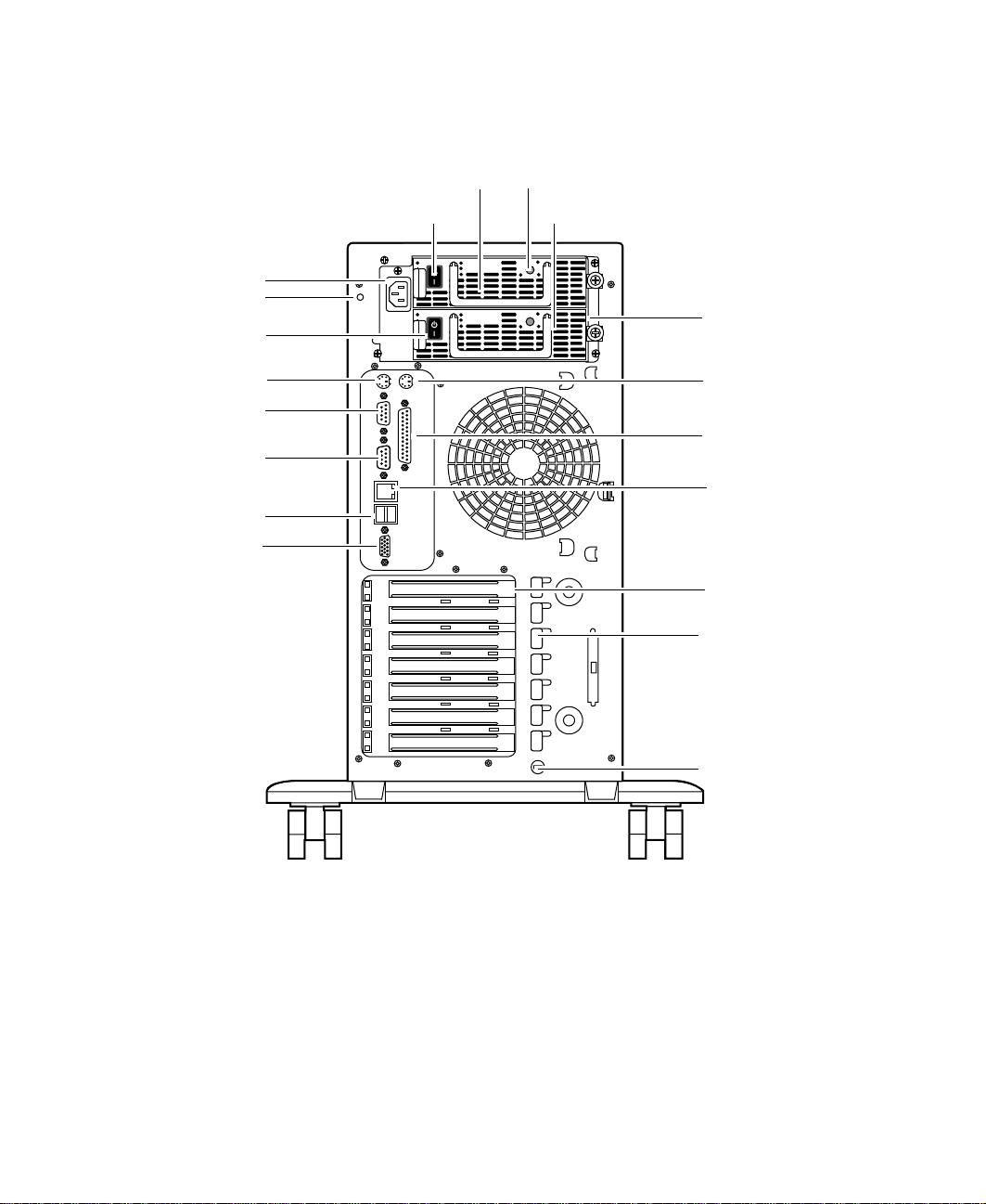
Back panel
Power connector
Power supply
cable clamp
Module power
switch
Keyboard po rt
Serial port A
Serial port B
USB ports
Video port
Power supply module
Module power switch
Power supply module LED
Power supply module
Redundant power
supply
Mouse port
Parallel port
Network port
Expansion
card slots
Expansion card
retention clips
Module power swi tches (2) provide independent power control for e ach
redundant power supply module.
Power supply modules (2) provide redundant power and hot-swap capability
to power the server with minimal downtime.
Redundant power suppl y provides two hot-swappable power supply modules
that can independently support the server’s power requirements.
4 System Features
Kensington
lock slot
Page 12

PS/2 power suppl y (not shown) provides sufficient power to r un the serve r
at a reduced cost.
Mouse port connects a PS/2-compatible mouse.
Parallel port connects a printer or other parallel device.
Network port lets you connect to a network. The adjacent indicator LEDs
show LAN activity (yellow) and 100 Mbit speed (green).
Expansion card slots (7) allow you to install up to four 32-bit, 33 MHz PCI
expansion cards, two 32-bit, 66 MHz PCI expansion cards, and one ISA
expansio n card.
Expansion card retention clips (7) allow screwless retention of the
expansion cards for ease of maintenance and installation.
Kensington lock slot lets you install a security cable and lock.
Video por t connects the first (or only) monitor interface cable. The video
controller is integrated in the system board.
USB ports connect external P lug-and-Play device s, such as printers and
pointing devices, that are automatically configured when they are plugged
into the computer through one of these ports. USB keyboards and mice are
not supported.
Serial ports (2) connect to serial devices.
Keyboard port connects a PS/2-compatible keyboard.
Power supply cable clamp secures the power supply cords so that they are
not accidentally pulled from the power supply.
Power connector connects the computer power cord. The other end of the
power cord plugs into an AC outlet or power strip.
Back panel 5
Page 13
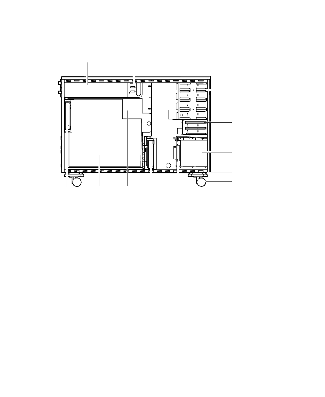
Interior of system
Power supply Power supply fans
Back
panel fan
System
board
System
board
tray
Hot-plug
cage fan
5.25-inch
drive bays
3.25-inch
drive bays
Hot-plug bays
(Hot-plug cage)
Outriggers
Castors
Hot-plug
backplane
Power supply provides power to the system components. The redundant
power supply provides hot-swap capability and fault tolerance.
Power supply fans (only available with redundant power supply) provid e
cooling for the redundant power supply modules.
5.25-inch drive bays provide space for up to four 5.25-inch drives. A CD drive
comes standard with the system and occupies one of the 5.25-inch drive bays.
3.25-inch drive bays support up to two 3.25-inch drives. A diskette drive
comes standard with the system and occupies one 3.25-inch drive bay. A hard
drive is typically installed in the second drive bay.
Hot-plug bays support up to six 1-inch high 3.25-inch SCA SCSI hard drives.
Empty drive bays contain empty carriers to control airflow and EMC
characteristics.
Outriggers provide support for the castors.
Castors let you move the unit easily for maintenance and servicing.
6 System Features
Page 14

Hot-plug backplane provides the control for the hot-plug drives.
Hot-plug cage fan provides cooling for the hot-plug drives and other internal
components.
System board tray supports the system board and makes it easier to remove
and install.
System board see “System board” on page 8.
Back panel fan provides cooling for system board components and additional
cooling for the power supply.
Interior of system 7
Page 15
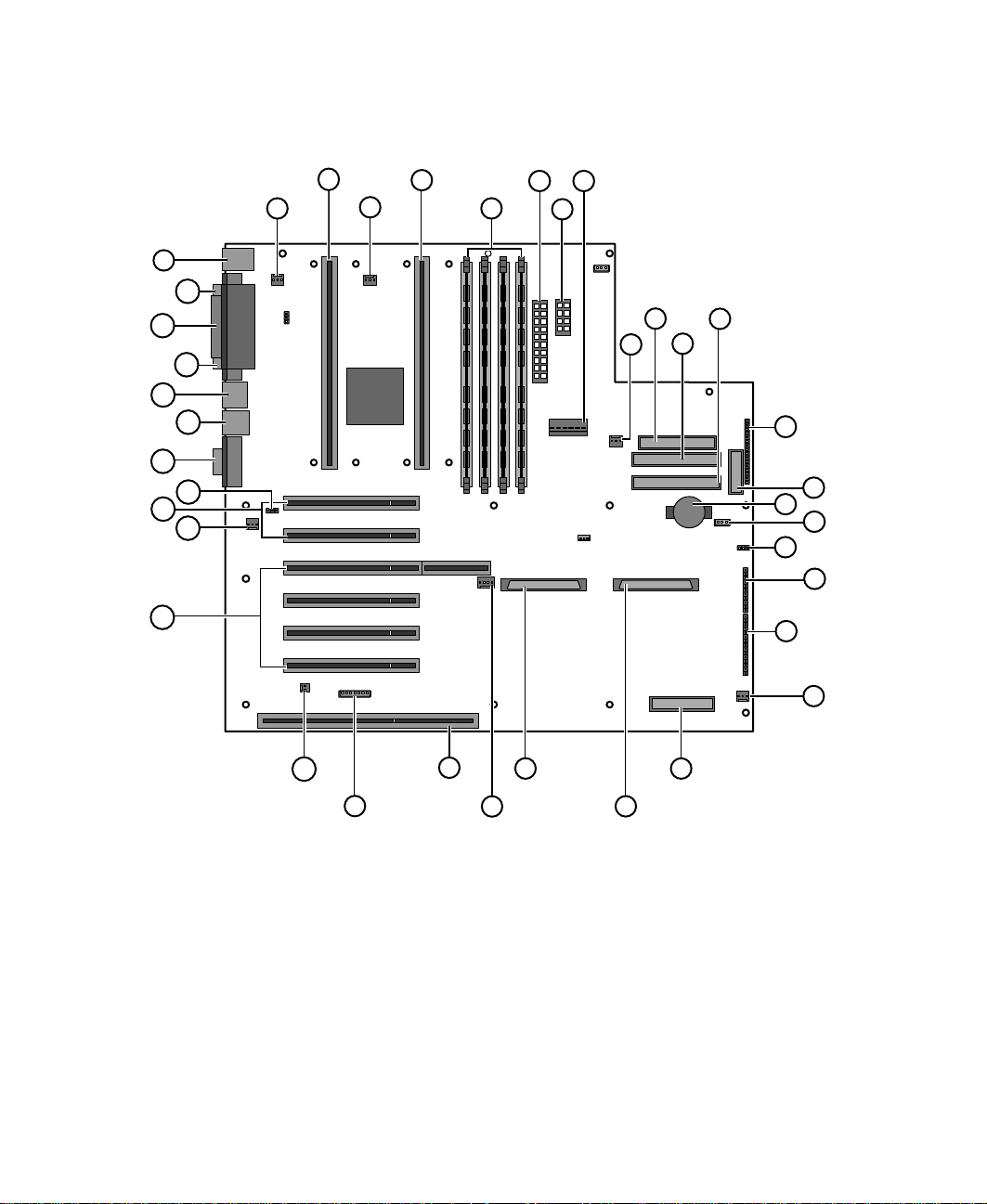
System board
AL
AJ
AH
AF
AD
AB
AK
AI
AG
AE
AC
B
A
D
C
F
H
E
G
J
I
L
K
M
N
O
P
Q
R
S
T
AA
A Secondary processor fan connector
B Secondary processor connector
C Primary processor fan connector
D Primary processor connector
E DIMM slots (4)
F Main power connector, 24-pin
8 System Features
Y
Z
W
X
V
U
Page 16

Auxiliary power connector, 10-pin (not used)
G
H ATX auxiliary power connector, 6-pin
I Fan connector (not used)
J Di skette drive connector
K Primary IDE connector
L Secondary IDE connector
M AT X fr o nt pa n el c on ne c to r
N Front panel connector, 16-pin
O Battery
P Isolated ser ver management (ISOL) intelligent management bus
(IMB) connector (not used)
Q Jumper J4J2 (BMC boot block write enable)
R Jumper block (jumper J3J1)
S Jumper block (jumper J2J1)
T Fan connector (hot-plug drive bay fan)
U Server monitor module (SMM) feature connector
V Ultra wide SCSI connector
W Ultra2 SCSI connector
X Hard drive LED connector
Y ISA connector
Z Intelligent chassis management bus (ICMB) connector (not used)
AA Chassis intrusion connector (not used, chassis intrusion is
communicated through the front panel connector)
AB PCI 32-bit, 33 MHz connectors
AC Fan connector (back panel fan)
AD PCI 32-bit, 66 MHz connectors
AE Wak e o n L AN j u mp e r
System board 9
Page 17

AF Video connec tor
AG Dual USB co nnectors
AH RJ-45 Ethernet LAN connector and LEDs
AI Serial Port A
AJ Parallel port
AK Serial port B
AL Stacked key board and mouse ports
10 System Features
Page 18
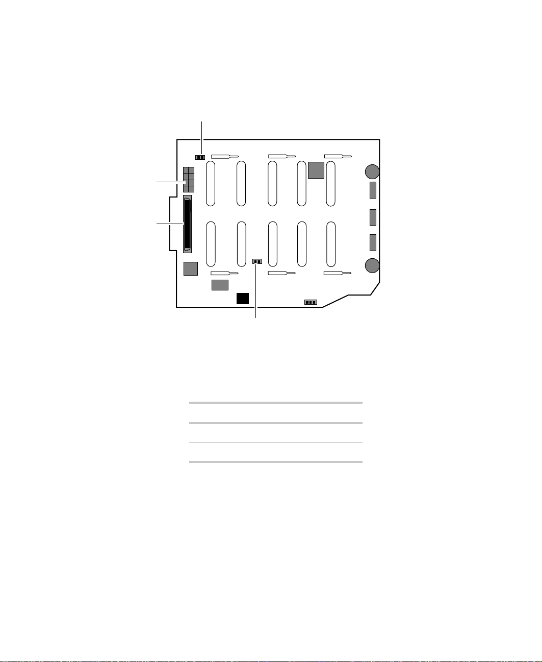
Hot-plug backplane
Back of the hot-plug backplane board
JP5: Delay start jumper
Power connector
SCSI connector
JP6: Termination jumper
JP5: Delay start jumper controls the spin-up sequence of the drives attached
to the backplane. If you enable delay start, the drives spin up one at a time
in order of their SCSI ID. If you disable delay start, all drives spin up
simultaneously. Set the jumper according to the table below.
Position Description
On (default) Enables delay start
Off Disables delay start
Hot-plug backplane 11
Page 19
JP6: Termination jumper enables or disables termination for the backplane.
The backplane is designed to occupy one end of the bus and is usually
terminated. If you configure the SCSI bus so the backplane is not at the end
of the bus, disable termination. Set the jumper according to the table below.
Position Description
On Termination is disabled
Off (default) Termination is enabled
SCSI connector provides the point of connection for the SCSI cable from the
RAID controller.
Power connector provides th e po i nt of connection f o r t he power cable from
the power supp ly.
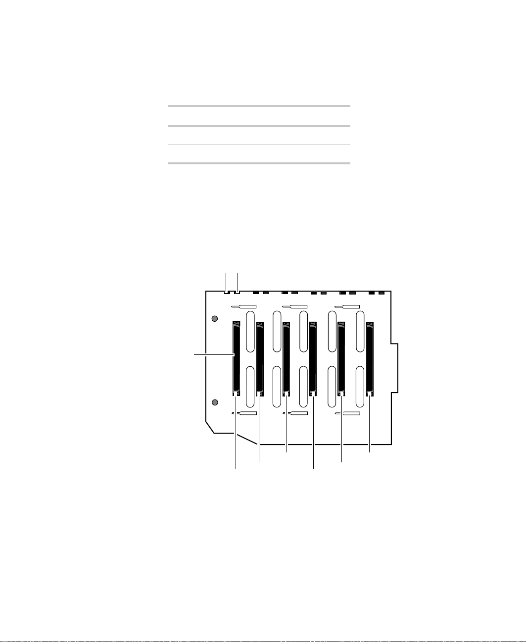
Front of the hot-plug backplane board
Drive activity LED (6)Reserved LED (6)
SCA SCSI drive connector (6)
Reserved LED (6) reserved for future use.
Drive activity LED (6) glows green when the drive is actively reading or
writing data.
SCA SCSI drive connector (6) provides the single point of connection for
the six SCA SCSI drives.
12 System Features
SCSI ID 1
SCSI ID 0
SCSI ID 2
SCSI ID 5
SCSI ID 4
SCSI ID 3
Page 20
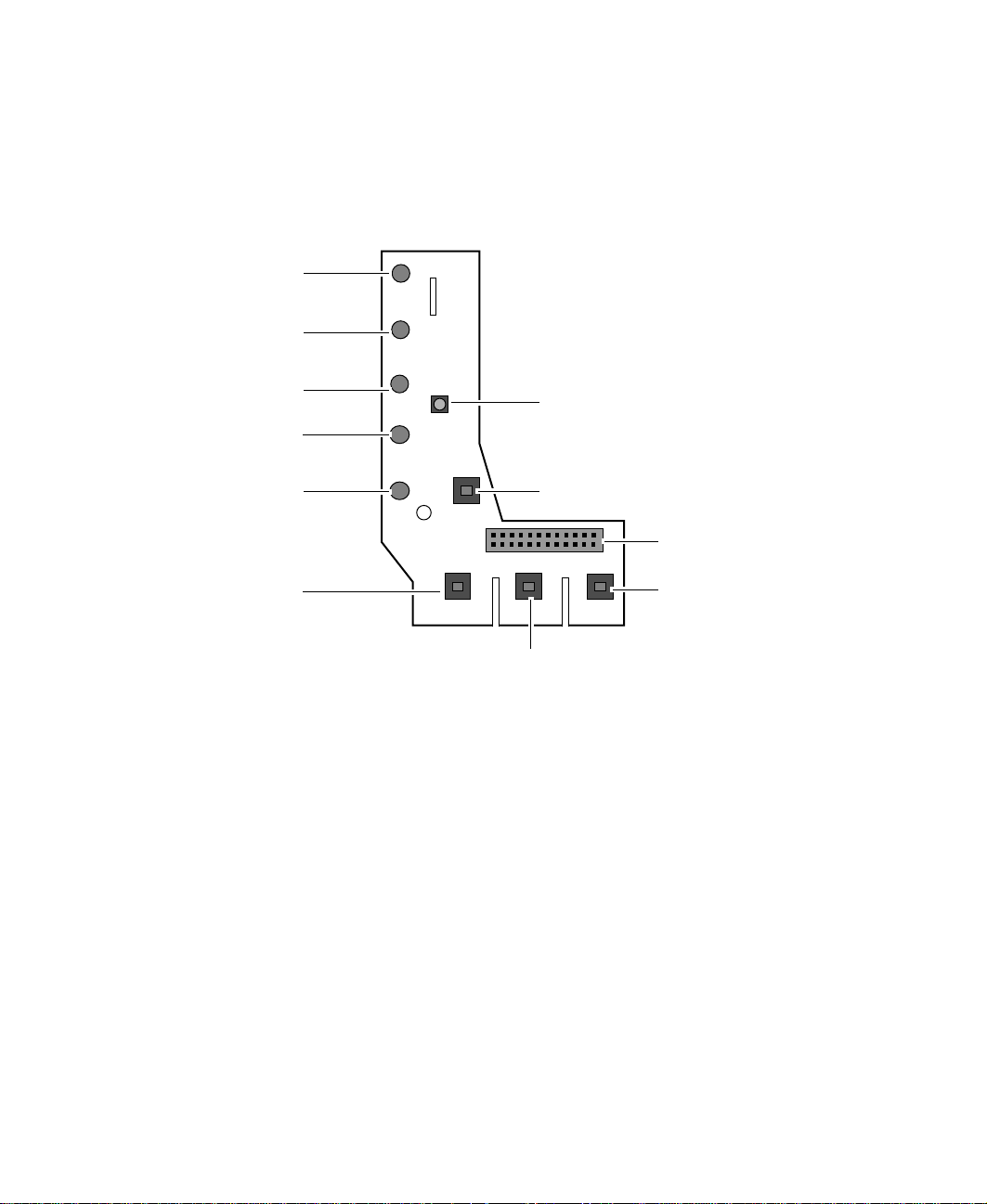
Front panel board
The front panel board supports the LEDs and buttons accessi ble from the front
panel. The buttons and LEDs on the front panel board are shown and
described below.
Power LED
Disk activity LED
Reserved LED
PS 1 status L ED
PS 2 status L ED
Reset button
NMI button
Chassis intrusion detection switch
Front panel connector
Power supply alarm
speaker reset button
Power button
Power LED that glows green whenever the system is turned on. The LED also
flashes when the system is in sleep mode.
Disk activity LED that glows green whenever any of the hard disks is actively
reading or writing data.
Reserved LED this LED is reserved for future use.
PS1 fault LED that flashes green whenever the first power supply module fails
or one of its power levels goes out of bounds.
PS2 fault LED that flashes green whenever the second power supply module
fails or one of its power levels goes out of bounds.
Reset button lets you reset the server if it has become nonresponsive.
Front panel board 13
Page 21

Power button turns the ser ver on and off. In an ACPI-enabled operatin g
system like Windows 2000, you can set the power button to enter sleep mode
rather than turning the system off.
Power supply alar m speaker reset butt on disables the p ower supply alarm
speaker. The alarm is not cleared and the appropriate LED continues to glow
until the failed power supply module is replaced. The alarm is only active on
systems using the N+1 redundant power supply.
NMI button allows a technician servicing the server to generate a
non-maskable interrupt (NMI) to help debug server errors.
Chassis intrusion detection switch sends a message to the system
management hardware logging an event when the front bezel is removed.
Front panel connector connects the controls on the front panel with the
system board.
14 System Features
Page 22

System Setup
Setting up the server
Use the instructions on the quick guide poster that came with the server to
assemble the server.
You can prepare a safer working environment before assem bling the server
by following these guidelines:
■ Use a clean, flat, and stable surface for the server. Allow at least 12 inches
at the rear of the computer for cabling and air circulation.
■ Obtain an adequately rated uninterruptible power supply (UPS). A UPS
protects against AC line spikes, power interruptions, and other power
fluctuations that may damage the server.
■ Protect the server from extreme temperature and h umidity. Do not
expose it to direct sunlight, he ater ducts, or other he at-generating objects.
■ Keep the computer away from equipment that generates magnetic fields,
such as unshielded stereo speakers. Even a telephone placed too close to
the computer may cause interference.
2
■ Plug the computer into a wall outlet, power strip, or uninterruptible
power supply (UPS). Make sure the power cords are secured in the power
supply cable clamp on the back panel.
Important Keep the boxes and packing material. If you need to send
the computer to Gateway for repairs, you must use the
original packaging or your warranty may be voided.
Setting up the server 15
Page 23
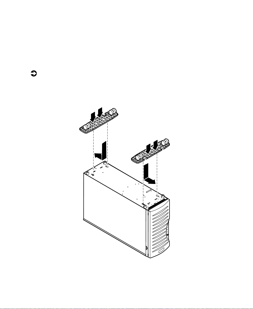
Installing the outriggers and castors
The tower chassis is shipped with s mall rubber feet to prevent it from slipping
and to minimize vibrations when the chassis is placed on a desktop. However,
if you intend to place the chassis on the floor, you may find it easier to
maintain the system if it has castors and can be rolled out for easier access.
To install the outriggers and castors:
1 Gently turn the chassis upside down, placing it on the top panel.
2 Align the outriggers and castors with the slots on the bottom panel of
the chassis.
16 System Setup
Page 24

Place the tabs on the outriggers into the corresponding slots on the
3
bottom panel and slide the outriggers toward the ends of the chassis.
4 Carefully return the chassis to the upright position.
Starting the server
Before you start the server for the first time:
■ The redundant power supply is autosensing. It automatically determines
the voltage of the incoming power source and compensates accordingly.
The optional PS/2 power supply has a voltage selector switch. Make sure
that the voltage selector switch on the PS/2 power supply is set to the
correct voltage for your area.
■ Make sure all cables are firmly connected to the proper ports on the back
panel of the computer.
Caution Electricity can flow from connected peripherals into the
system causing a shock. Make sure the server and
peripherals are turned off and unplugged from the power
outlet when you connect peripherals to the computer.
■ Make sure that both power supply modules in the redundant power
supply are turned on. (The PS/2 power supply does not need to be turned
on separately.)
■ Make sure the computer and monitor are plugged into an AC outlet,
power strip, or UPS and that the power strip or U PS is turned on.
To start the system:
1 If you have connected the system components to a power strip or UPS,
make sure all the system components are turned off, then turn on the
power strip or UPS.
2 Turn o n th e m o ni t o r.
3 Turn on the computer. Make sure the individual power buttons on the
power supply modules are turned on. The light-emitting diodes (LED) in
the power button and on each power supply module are on when the
power is on.
Starting the server 17
Page 25

4 Turn on any other components connected to the computer, such as
speakers, a printer, or a scanner.
If nothing happens when you turn on the system:
■ Make sure that the power cables are securely plugged in and that
the power strip or UPS (if you are using one) is plugged in and
turned on.
■ Make sure the monitor is connected to the computer , plugg ed into
the power strip, AC outlet, or UPS, and turned on. You may also
need to adjust the brightness and contrast controls on the monitor .
Understanding the Power-On Self-T est
When you turn on your computer, the power-on self-test (POST) routine
checks the system memory and components. To see this information on the
screen, press E
count.
The system displays an error message if POST finds any problems. Write down
any error messages that you see. If you continue to have problems, these error
messages may help you or Gateway technical support diagnose the cause.
SC during POST . Press SPACEBAR to bypass the remaining memory
Setting up the operatin g system
The first time you start the server, the operating system takes a few minutes
to set up.
Refer to your operating system documentation for specific questions regarding
the operating system.
To complete the operating system setup:
1 Aft er the computer starts, the start-up wizard opens. Continue by clicki ng
Next.
2 Type the requested information in the appro priate text boxes. When yo u
have finished typing the information, continue by clicking
3 Cont inue following the instructions and selecting options in the start-up
wizard dialog boxes, clicking
the wizard tells you to restart your computer.
18 System Setup
Next to move through the dialog boxes, until
Next.
Page 26

If you need to return to the previous dialog box to change any of your
4
entries, click
Back.
5 Restart the server. The setup is complete.
Important For other operating systems, such as Windows® 2000 or
®
Novell
softwar e manual.
Netware, refer to th e appropriate operat ing system
T urning off the server
Every time you turn off the server, shut down the operating system first. You
may lose data if you do not follow the proper procedure.
To turn off the server in Windows NT:
1 Click Start, then select Shut down the computer?, then Shut Down.
2 Click OK. The operating system shuts down. When you see a message
It is now safe to turn off your computer, turn off the computer by
saying
pressing the power button.
3 Turn off the monitor and peripherals.
Important For other operating systems, such as Windows 2000 or
Novell Netware, refer to th e ap prop riate operating system
softwar e manual.
Warning When you turn the computer off, some electric current still
flows through it. Before opening the computer case or
connecting or removing any peripherals, turn off the
computer, then unplug the power cord.
Turning off the server 19
Page 27

Resetting the server
If your computer does not respond to keyboard or mouse input, you may have
to close programs that are not responding. If closing u nresponsive prog rams
does not restore your computer to normal operation, you may have to reset
the system.
To close unresponsive programs and reset the ser ver in Windows NT:
1 Press CTRL+ALT+DEL. A window opens that lets you close a program that
is not responding.
2 Click Tas k M a n a g er , then select the program that is not responding.
3 Close the program by clicking End Task.
4 If the computer does not respond, press the reset button to restart the
computer.
As a part of the regular startup process, a program to check the disk status
runs automatically. When the checks are finished, Windows starts.
Important For other operating systems, such as Windows 2000 or
Novell Netware, refer to th e ap prop ria t e op era ting sy st em
softwar e manual.
20 System Setup
Page 28

Case Access
The Gateway 7210 Server is designed as a toolless chassis. None of the normal
user-serviceable parts require a tool of any kind to remove, install, or replace.
In some cases, where the pieces fit very tightly, a tool may make the job easier.
The various clips, tabs, thumbscrews, and other devices that allow toolless
construction are color-coded in green to show you where they are. Most of
these devices are either self-explanatory or very easy to figure out.
When in doubt, the steps and illustrations provided in thi s manual sh ow you
the way to remove any device you may need to replace.
3
21
Page 29

Preventing static electricity discharge
Before opening the computer case, follow these precautions to preven t
damage from static electricity. When opening your computer case, always
perform the following procedur e.
Caution Static electricity can permanently damage electronic
component s in your co mputer. Prevent el ectrosta tic
damage to your computer by following static electricity
precautions every time you open your computer case.
To prevent static electricity discharge:
1 Turn off the computer power.
2 Touch a bare metal surface on the back of the computer.
3 Unplug all power cords from AC outlets and disconnect the modem cable
(if installed).
Also follow these static electricity precautions:
■ Avoid static-causing surfaces such as plastic and packing foam in your
work area.
■ Remove the parts from their antistatic bags or containers only when you
are ready to use them. Do not lay parts on the outside of an antistatic
bag or container because only the inside provides antistatic protection.
■ Always hold cards by their edges and their metal mounting brackets.
Avoid touching components on the cards and the edg e connectors that
connect to expansion slots. Never slide cards or other parts over any
surface.
22 Case Access
Page 30

Opening the case
Important All references to front, back, left, or right on the computer
are based on the computer being in a normal, upright
position, as viewed from the front.
The only components that are accessible from outside of the chassis are the
front panel indicator lights. To access any of the removable media drives, the
hot-plug drives, or the power and reset switches you must open the bezel door .
To work on the internal components of the computer, you must open the
chassis, which has two removable parts:
■ A bezel that covers the front of the chassis
■ A side panel that permits access to the interior of the case
Because the components inside the computer are extremely sensitive to static
electricity, make sure you follow the precautions at the beginning of this
chapter to avoid stati c electricity damage .
Only qualified personnel should open the system for maintenance. If you are
qualified to maintain the system yourself, make sure you are properly
grounded before opening the system chassis.
Warning Avoid exposure to dangerous electrical voltages and
moving parts by turnin g of f y our co mputer and unplu gging
the power cord and modem cable (if installed) before
removing the chassis cov er.
Opening the case 23
Page 31

Opening the bezel door
The bezel door covers the removable media drives, the hot-plug drives, and
the front panel controls. T o access these components, you must open the bezel
door.
To open the bezel door:
1 If the bezel door is locked, unlock it.
2 Grip the bezel door handle next to the front panel indicator lights and
pull the door open.
Chassis lock
24 Case Access
Front panel
door
Page 32

Removing the front bezel
The locking front bezel provides secure access to the system co mponents. You
must unlock and remove the front bezel before you c an remove the side panel
and access the interior of the system.
To remove the front bezel:
1 Power down, turn off, and disconnect all power to the server.
2 Obs erve all safety and static electricity precautions, see “Preventing static
electricity discharge” on page 22.
3 Unlock the front bezel, if it is not already unlocked.
4 Press the tabs at the sides of the bezel and pull the top of the bezel away
from the server.
5 Lift the bezel away from the chassis.
Opening the case 25
Page 33

Removing the side panel
The side panel cannot be removed unless the front bezel has already been
removed. The side panel provides access to all of the internal components of
the server.
To remove the side panel:
1 Turn off the computer and disc onnect all power cords.
2 Obs erve all safety and static electricity precautions, see “Preventing static
electricity discharge” on page 22.
3 Remove the front bezel as described in “Removing the front bezel” on
page 25.
4 Loosen the three thumbscrews from the left side of the front panel.
5 Slide the side panel to the front, disengaging the retaining tabs on the
top edge of the panel from the top of the chassis.
6 Lift the panel out and away from the chassis.
26 Case Access
Thumbscrew
Thumbscrew
Thumbscrew
Page 34

Closing the case
Close the chassis as soon as you finish installing or removing components
so that dust and dirt do not collect inside the computer.
Replacing the side panel
Closing the side panel covers the internal components. You must close the
side panel and replace the front bezel before you can operate th e server. If
you do not, a system intrusion event is logged by the system management
hardware. Be careful not to pinch any cables in the panel as you replace it.
To replace the side panel:
1 Hold the side panel at an angle to the chassis and 3/4-inch forward.
Engage the retaining tabs on the bottom edge of the panel with the slots
at the bottom edge of the chassis.
2 Swing the top of the panel toward the chassis, engaging the retaining
tabs on the top edge of the side panel with the slots on the chassis.
3 Slide the panel toward the back of the chassis 3/4-inch, securing it in
place.
Closing the case 27
Page 35

4 Tighten the thumbscrews.
28 Case Access
Page 36

Replacing the front bezel
Once the side panel is in place, you must replace the bezel to operate the
server. If the server is run without the bezel installed, a chassis intrusion ev ent
is logged by the system management hardware.
To replace the front bezel:
1 Holding the bezel at an angle to the front of the chassis, place the hinge
slot on the bottom of the bezel over the flange on the bottom edge of
the chassis.
2 Swi ng the top of the bezel toward the chassis until the retaining tabs snap
into place.
3 Lock the front panel lock, if necessary.
Closing the case 29
Page 37

Closing the bezel door
Close the bezel door to prevent accidental or unauthorized ac cess to the server
controls, hot-plug drives , and removable media dri ves.
To close the bezel door:
1 Swing the bezel door to the left and press it firmly into place.
2 Lock it if necessary.
30 Case Access
Page 38

Replacing and Adding Internal Devices
The Gateway 7210 Server is designed as a toolless chassis. None of the normal
user-serviceable parts require a tool of any kind to remove, install, or replace.
In some cases, where the pieces fit very tightly, a tool may make the job easier.
The various clips, tabs, thumbscrews, and other devices that allow toolless
construction are color-coded in green to show you where they are. Most of
these devices are either self-explanatory or very easy to figure out.
When in doubt, the steps and illustrations provided in thi s manual sh ow you
the way to remove any device you may need to replace.
4
31
Page 39

Drives
There are several types of drives and similar devices that can be installed in
the server. All drives are easy to install and require no tools to replace.
Preparing to replace or add a drive
One 3.5-inch diskette drive, one 3.5-inch hot-plug hard drive, and one CD
drive are included with the computer. You can add additional drives of the
following types:
■ 1-inch high, 3.5-inch hot-plug drives.
■ Half-height 3.5-inch hard drives - The system board has two IDE
connectors that support as many as two drives each. IDE drives include
the IDE CD drive.
■ Half-height 5.25-inch devices.
As you prepare to install drives, keep the following in mind:
■ If you remove a drive, place it in an antistatic bag or container.
■ Before you install a drive, see the drive documentation for information
on configuring the drive, setting any jumpers on the driv e, and attaching
cables to the drive.
■ If you are installing a drive that uses an add-in controller, install the
expansion card before you install the drive.
■ IDE hard drives can be configured as single, master, or slave. IDE
CD drives can be configured as master or slave. Co nfigure the drives by
using the drive-select jumpers located on the drives.
■ If only one drive is attached to a controller cable, configure the drive as
single if it is a hard drive or master if it is a CD-ROM drive. If two drives
of any type are attached to the cable, configure one as master and one
as slave.
■ You may need to configure the drives you install using the BIOS Setup
utility. Select F2 at start up to open the BIOS Setup utility.
32 Replacing and Adding Internal Devices
Page 40

Drive cabling information
The system includes five different types of drive cables. Each drive cable is
clearly labeled, indicating the cable type and showing which end to connect
to the appropriate connector on the system board and which end to connect
to the drive.
■ Use the diskette drive connector cable to connect the diskette drive.
■ Use the standard IDE conn ector cable to connect IDE de vices such as
CD drives and standar d IDE hard drives.
■ Use the IDE DMA-66 cable to connect DMA-66-compatible hard drives.
■ Use the SCSI SE cable to connect single-ended SCSI devices. This cable
requires termination, either on the device or as a plug-in terminator on
the cable.
■ Use the SCSI LVD cable to connect the hot-plug backplane to the
integrated SCSI controller on the system board.
Replacing the diskette drive
The diskette drive is near the bottom of the stack of drive bays. If the diskette
drive included with the system fails, replace the drive.
To replace the diskette drive:
1 Turn off the system and disconnect the power cord and all other external
peripheral de vices.
2 Open the case. (See “Opening the case” on page 23 and “Preventing static
electricity discharge” on page 22.)
3 Locate the 3.5-inch diskette drive.
4 Remove the power and data cables from the back of the drive, noting
their locations and orientations. (Y ou will reconnect these cables after you
install the new drive.)
The 3.5-inch diskette drive is secured in the chassis by a set of removable
rails. The rails let the drive slide into and out of the guides in the front
bay.
Drives 33
Page 41

5 Disengage the rail locking tabs by pressing in on both front rail
extensions, then move the drive slightly out of the bay by pushing on
the back of the drive.
6 Pull the drive out of the chassis.
7 Remove the ra ils on both side s of the driv e and sna p them onto the new
drive in the same positions. The rails are labeled. Make sure the front
rail extensions are towards the front of the drive.
Important The rails on the 3.5-inch diskette drive are different from
those on the hard drive and the CD drive. Make sure you
install the correct ra ils on each d rive.
8 Align the rails with the appropriate open bay, then slide the drive into
the bay until the locking tabs snap into place.
9 Connect the power and data cables, making sure the cables are in their
original positions. (See your drive documentation for proper drive jumper
settings and cable orien tation.)
10 Close the case. (See “Closing the case” on page 27.)
11 Reconnect the power cord and all other external peripheral devices, then
turn on the system.
34 Replacing and Adding Internal Devices
Page 42

Replacing the optional boot drive
An optional IDE hard drive can be shipped with the server. This drive is
mounted at the bottom of the drive stack accessible from the front of the
chassis.
To replace the optional boot drive:
1 Turn off the system and disconnect the power cord and all other external
peripheral de vices.
2 Open the case. (See “Opening the case” on page 23 and “Preventing static
electricity discharge” on page 22.)
3 Locate the 3.5-inch hard drive at the bottom of the drive stack.
4 Remove the power and data cables from the hard drive.
5 Grip the mounting rails firmly with thumb and index finger and pull
the drive carefully straight out of the drive stack.
6 Remove the mounting rails from the hard drive.
7 Place the old drive in an antistatic bag or container, then place the new
hard drive on a static-free surface with the top up and the connectors
facing you.
Drives 35
Page 43

8 Install the two drive mounting rails to the new hard drive, making sure
the front rail extensions are towards the front o f the device. The rails a re
labeled.
9 Align the rails with the open bay at the bottom of the drive stack, then
slide the drive into the stack until the locking tabs snap i nto place (make
sure that the data and power connectors o n the drive face the inside of
the server).
10 Connect the power and data cables to the drive. (See the drive
documentation for proper cable orientation.)
11 Close the case. (See “Closing the case” on page 27.)
12 R econnect the power cord and all other external peripheral devices, then
turn on the system.
36 Replacing and Adding Internal Devices
Page 44

Replacing a hot-plug drive
The hot-plug drives are located at the bottom of the front panel. The hot-plug
bay supports as many as six 1-inch high 3.5-inch SCA-II SCSI hard drives.
The hot-plug drives are assigned SCSI ID numbers by the hot-plug backplane
with the drive at the far left side of the hot-plug bay assigned SCSI ID 0. The
backplane assigns SCSI IDs to the other drives in order up to SCSI ID 5 at the
far right side of the hot-plug bay.
Important Gateway tests and verifie s the operatio n and compati bility
of the drives we sell. Addit ional or replacement drive s must
conform to Gateway standards, especially in a RAID or
mission-critical environment.
SCSI ID 0
SCSI ID 1
SCSI ID 2
SCSI ID 3
SCSI ID 4
SCSI ID 5
Install drive in the left-most drive bay first and in increasing order by SCSI
ID number thereafter.
Drives 37
Page 45

To replace a failed drive:
1 Before you remove the failed drive, use the appropriate software and
utilities installed on the system to stop all activity on the failed drive.
Instructions for using the software are provided by the software
manufacturer.
2 Use the utilities to determine which drive needs to be replaced.
3 If the drive carrier is locked, use the hex key to unlock the carrier . Locked
drive carriers show a red flag in the slot on the carrier handle.
4 Remove the drive from the drive bay by pressing down on the carrier
handle and rotating the handle out and down from the front of the server .
38 Replacing and Adding Internal Devices
Page 46

Continue pulling outward until the drive is entirely out of the system.
5
Drives 39
Page 47

6 Remove the four screws that secure the drive to the carrier, then remove
the drive.
7 Install the new drive in the carrier using the four screws you removed
in Step 6.
8 Align the drive rails with the slots at the top and bottom of the drive
bay. Leave the handle in the down po sition.
9 Push the drive all of the way into the drive bay until the handle starts
to close because of contact with the front of the chassis. Make sure the
hooks on the bottom of the handle latch over the edge of the drive bay
and firmly close the handle.
10 Lock the drive carrier with the hex key.
40 Replacing and Adding Internal Devices
Page 48

Run any necessary utilities to inform the system that the new drive is
11
installed and ready for use. See the utility software documentation for
details.
Adding a hot-plug drive
The hot-plug drives are located at the bottom of the front panel. The hot-plug
bay supports up to six 1-inch high 3.5-inch SCA LVD SCSI hard drives.
The hot-plug drives are assigned SCSI ID numbers by the hot-plug backplane
with the drive at the far left side of the hot-plug bay assigned SCSI ID 0. The
backplane assigns SCSI IDs to the other drives in order up to SCSI ID 5 at the
far right side of the hot-plug bay.
SCSI ID 0
SCSI ID 1
SCSI ID 2
SCSI ID 3
SCSI ID 4
SCSI ID 5
Install drive in the left-most drive bay first and in increasing order by SCSI
ID number thereafter.
Drives 41
Page 49

Removing an empty drive carri er
If the system ships with less than six drives installed, the empty drive bays
contain drive carriers. To remove a drive carrier, follow the instructions to
remove a drive in “Replacing a hot-plug drive ” on page 37.
Purchase additional SCSI drives through your Gateway sales representative.
Specify the system into which you will install the drive to ensure that the
correct drive is delivered.
Important Gateway tests and verifie s the operatio n and compati bility
of the drives we sell. Addit ional or replacement drive s must
conform to Gateway standards, especially in a RAID or
mission-critical environment.
If you need to replace an empty drive carrier in the system, make sure it slides
straight into place until the plastic handle begi ns to move upward, then close
the handle.
To remove an empty drive carrier:
1 If the drive carrier is locked, use the hex key to unlock the carrier . Locked
drive carriers show a red flag in the slot on the carrier handle.
2 Remove the drive carrier from the drive bay by pressing down on the
carrier handle and rotating the handle out and down from the front of
the server.
42 Replacing and Adding Internal Devices
Page 50

Continue pulling outward until the drive carrier is entirely out of the
3
system.
Drives 43
Page 51

Installing a SCSI drive in the ser ver
You do not need to configure individual drives before you install them in the
server.
To install a SCSI drive in the server:
1 Remove the empty drive carrier as described in “Removing an empty
drive carrier” on page 42.
2 Remove the four screws that secure the support bracket and front
assembly to the rails. The two screws that secure the front assembly are
threaded through small nuts. The nuts are not used when you install a
drive.
Nuts
Front
assembly
Support
bracket
44 Replacing and Adding Internal Devices
Rails
Page 52

Install the drive into the carrier using the four screws you removed in
3
Step 2.
4 Ali gn the drive rails with th e slots at the top and botto m of the drive b ay.
Drives 45
Page 53

5 Leave the handle down and push the drive all of the way into the drive
bay until the handle begins to close because of contact with the front
edge of the server.
6 Make sure the hooks on the bottom of the handle latch over the edge
of the drive bay, then firmly close the handle.
7 Secure the drive by locking the drive carrier with the hex key.
Replacing the CD drive
The CD drive is located in on e of the 5.25-inch driv e bays at the top of the
drive stack in the front of the chassis.
To replace the CD drive:
1 Turn off the system and disconnect the power cord and all other external
peripheral de vices.
2 Open the case. (See “Opening the case” on page 23 and “Preventing static
electricity discharge” on page 22.)
3 Locate the 5.25-inch CD drive.
46 Replacing and Adding Internal Devices
Page 54

Remove the power and data cables from the back of the drive, noting
4
their locations and orientations. (Y ou will reconnect these cables after you
install the new drive.)
5 Disengage the rail locking tabs by pressing in on both front rail
extensions, then move the drive slightly out of the bay by pushing on
the back of the drive.
6 Pull the drive out of the chassis.
7 Remove the ra ils on both side s of the driv e and sna p them onto the new
drive in the same positions. The rails are labeled. Make sure the front
rail extensions are towards the front of the drive.
Important The rails on the CD drive are different from those on the
3.5-inch drives. Make sure you install the correct rails on
the CD drive.
8 Align the rails with the open bay, then slide the drive into the bay until
the locking tabs snap into place .
9 Connect the power and data cables, making sure the cables are in their
original positions. (See your drive documentation for proper cable
orientation.)
10 Close the case. (See “Closing the case” on page 27.)
11 Reconnect the power cord and all other external peripheral devices, then
turn on the system.
Drives 47
Page 55

Adding additional 5.25-inch devices
You can use the three additional, externally accessible 5.25-inch drive bays
to install additional 5.25-inch devices such as a CD writer or a tape backup
drive. Use the rails from the exi sting filler t rays to i nstall new driv es. You may
need to purchase an addit ional cable of suffici ent length to connec t the
existing devices and the new device to the connector on the system board.
To install an additional 5.25-inch device:
1 Turn off the system and disconnect the power cord and all other external
peripheral de vices.
2 Open the case. (See “Opening the case” on page 23 and “Preventing static
electricity discharge” on page 22.)
3 Remove the filler tray from the front of the drive bay, by pressing in on
both front rail extensions, then move the tray slightly out of the bay by
pushing on the back of the tray.
Caution The server was designed to adhere to electromagnetic
interference requirements and the tray is an integral part
of the system. Installing an approved device should
continue to maintain those st andards. I f you remo ve the
device you must reinstall the tray.
4 Snap the rails onto the drive, making sure the front rail extensions are
towards the front of the device. The rails are labeled.
5 Ali gn the rails with the bay, and slide the drive into the chassis until the
locking tabs snap into place.
48 Replacing and Adding Internal Devices
Page 56

Connect the power and data cables, making sure the cables are in their
6
original positions. (See the drive documentation for proper cable
orientations.)
7 Close the case. (See “Closing the case” on page 27.)
8 Reconnect the power cord and all other external peripheral devices, then
turn on the system.
9 Run the configuration software, if required.
Drives 49
Page 57

Memory
Four DIMM sockets on the system board support up to 2.0 Gigabytes (GB) of
PC/100 SDRAM.
Replacing memory
The DRAM DIMMs supported by the system board conform to the fo llowing
standards:
■ 64 MB, 128 MB, 256 MB, and 512 MB ECC DIMMs
■ PC/100-compliant, unbuffered, ECC SDRAM
■ 64 MB minimum system memory
■ 2.0 GB maximum system memory
When you select and install DIMMs, keep the following in mind:
■ Registered DIMMs should not be combined with unbuffered DIMMs
■ Memory should be added in order, from DIMM 1 to DIMM 4.
■ There can be no empty slots between installed DIMMs.
■ No jumper settings are required for the memory size or type because the
BIOS automatically detects this information.
To replace DIMMs:
1 Turn off the system and disconnect the power cord and all other external
peripheral de vices.
2 Open the case. (See “Opening the case” on page 23 and “Preventing static
electricity discharge” on page 22.)
3 Pull open the socket clamps on each side of the DIMM socket, then lift
the DIMM out of the socket. Store the DIMM in an anti-static container.
50 Replacing and Adding Internal Devices
Page 58

Insert the new DIMM into the socket and align the two notches in the
4
DIMM with the two notches in the DIMM socket.
5 Gently press th e DIMM into the socket until it is firmly sea ted. Inserting
the DIMM automatically locks the socket clamps on each end of the
DIMM.
6 Close the case. (See “Closing the case” on page 27.)
7 Reconnect the peripherals and the power cord, then turn on the system .
Memory 51
Page 59

Adding memory
The DRAM DIMMs supported by the server board conform to the following
standards:
■ 64 MB, 128 MB, 256 MB, and 512 MB ECC DIMMs
■ PC/100-compliant, unbuffered, ECC SDRAM
■ 64 MB minimum system memory
■ 2.0 GB maximum system memory
When you select and install DIMMs, keep the following in mind:
■ Registered DIMMs should not be combined with unbuffered DIMMs
■ Memory should be added in order, from DIMM 1 to DIMM 4.
■ There can be no empty slots between installed DIMMs.
■ No jumper settings are required for the memory size or type because the
BIOS automatically detects this information.
To add DIMMs:
1 Turn off the system and disconnect the power cord and all other external
peripheral de vices.
2 Open the case. (See “Opening the case” on page 23 and “Preventing static
electricity discharge” on page 22.)
3 Pull open the socket clamps on each side of the DIMM socket.
4 Insert the new DIMM into the socket and align the two notches in the
DIMM with the two notches in the DIMM socket.
52 Replacing and Adding Internal Devices
Page 60

Gently press the DIMM into the socket until it is firmly seated. Inserting
5
the DIMM automatically locks the socket clamps on each end of the
DIMM.
6 Close the case. (See “Closing the case” on page 27.)
7 Reconnect the peripherals and the power cord, then turn on the system .
Processors
The system is compatible with the Intel® Pentium® III 600 MHz and faster
processors with 100 MHz front-side bus (FSB). As many as two processors may
be installed in the system. The voltage regulator modules for both processors
are built into the system board and you do not need to install additional
VRMs.
Replacing a processor
When replacing a processor, order a processor upgrade kit from Gateway. The
kit includes the processor, a fansink or heatsink, and a disposable grounding
wrist strap.
Caution A heatsink or fa nsink must be inst alled o n each process or.
Installing a processor without a heatsink or fansink could
result in damage to, or failure of, the processor.
To replace a processor:
1 Turn off the syst em and disconnect the power cord and a ll external
peripheral de vices.
2 Open the case by following the instructions on page 23. (See “Preventing
static electricity discharge” on page 22.)
3 Disconnect the processor fan cable from the processor fan connector on
the system board.
4 Place the head of a flat-bladed screwdriver behind the tab on one side
of the processor retention bracket holding the processor to be removed.
Processors 53
Page 61

5 Push the handle of the screwdriver toward the processor. When the tab
that locks the processor in place opens, lift up slightly on the side of the
processor.
6 Repeat the previous two steps for the other side of the processor.
7 Pull the processor up and out of the slot.
54 Replacing and Adding Internal Devices
Page 62

Align the new processor with the processor slot (note that the processor
8
slot is keyed so the processor can only be installed one way) and press
firmly to install it.
9 Reco nnect the processor fan cable to the processor fan connector on the
system board.
10 Close the case. (See “Closing the case” on page 27.)
11 Reconnect the power cord and all other cords you removed, then turn
on the system.
Important Gateway recommends that you run a processor retest from
the BIOS Setup utility whenever you replace or add a
processor.
Processors 55
Page 63

Adding a processor
The system is compatible with the Intel® Pentium® III 600 MHz and faster
processors with 100 MHz front-side bus (FS B). As many as two processors may
be installed in the system. The second processor must match the first processor
in speed or the system functions at the speed of the slowest processor.
When adding a second processor order a processor upgrade kit from Gateway .
The kit includes the processor, a fansink or heatsink, and a disposable
grounding wrist strap.
Caution You must install a heatsink or fansink on each processor.
Installing a processor without a heatsink or fansink could
result in damage to, or failure of, the processor.
To add a second processor:
1 Turn off the syst em and disconnect the power cord and a ll external
peripheral de vices.
2 Open the case. (See “Opening the case” on page 23 and “Preventing static
electricity discharge” on page 22.)
3 Remove the terminator card from the second processor slot to make room
for the additional processor.
56 Replacing and Adding Internal Devices
Page 64

Align the new processor with the processor slot. Note that the processor
4
slot is keyed so the processor can only be installed one way. Press it firmly
to install it.
5 Connect the processor fan cable to the second processor fan connector
on the system board (See “System board” on page 8 for location).
6 Close the case. (See “Closing the case” on page 27.)
7 Reconnect the power cord and all other cords you removed, then turn
on the system.
Important Gateway recommends that you run a processor retest from
the BIOS Setup utility whenever you replace or add a
processor.
Processors 57
Page 65

Replacing the battery
The battery provides power for the system real-time clock and CMOS memory ,
which holds the system configuration information.
If your battery is failing you may notice the server clock slowing down and
giving you the incorrect time.
Open the BIOS Setup utility and write down all the values in the various
menus before replacing the battery . Replacing the battery resets the BIOS Setup
utility to its default values.
Warning Danger of explosion if battery is incorrectly replaced.
Replace only with the same or equivalent type
recommended by manufacturer.
Dispose of used batteries according to manufacturer’s
instructions.
Warnung Explosionsgefahr bel falsch eingebautter batterie.
Ersetzen der batterien nu r mit batterien de s gleichen typs
oder mit batterien vom hersteller empfohlenen typs.
Entsorgen gebrauchter batterien entsprechned
herstellerangaben.
Attention Il y a danger d’explosion s’il y a replacement incorrect de
la batteri e.
Remplacer uniquement avec une batterie du même type
ou d’un type équivalent reco mmandé par le constructeur.
Mettre au rebut les batteries usagées conformément aux
instructions du fabricant.
To replace the battery:
1 Restart the computer and start the BIOS Setup utility.
2 Write down the CMOS values from each tab in the BIOS Setup utility so
you can reenter them after you replace the battery . For more information
about the BIOS Setup utility, see “About the BIOS Setup utility” on
page 83.
58 Replacing and Adding Internal Devices
Page 66

Turn off the computer, disconnect the power cord and all external
3
peripheral de vices.
4 Open the case by following the instructions on page 23. (See “Preventing
static electricity discharge” on page 22.)
5 Locate the battery on the system board (see “System board” on page 8).
The battery is circular and has the positive pole mark (+) on the top.
6 Usi ng a small, flat-bladed screwdriver, carefully remove the battery from
its socket on the system board.
7 Press the new battery in the socket with the positive pole up. Be sure you
have pressed the battery down far enough for it to contact the base of
the socket (it should snap into place).
8 Close the case, as described in “Closing the case” on page 27.
9 Reconnect the peripherals and the power cord, then turn on the system .
10 If the CMOS data is no t correct, change the information in the BIOS Setup
utility using the data you recorded in Step 2.
Tr oubleshooting the battery installati on
If you have problems after installing the new battery, tr y each of the items
listed below, restarting the computer after each try.
■ Tu rn off the c omputer and make sure that all exterior cables a re attached
and secured to the correct co nnectors.
■ Make sure that all power switches are on. If the computer is plugged i nto
a power strip or surge protector, make sure it is turned on also.
■ Enter the BIOS Setup utility and compare the settings on the screen with
your notes or the system hardware manuals. Correct any discrepancies.
Replacing the battery 59
Page 67

■ Turn off the computer, remove the cover, and make sure that all cables
inside the case are attached securely. Also, make sure that the colored
cable edges are aligned c orrectly and that the conn ectors did not miss
any pins. Disconnect and reconnect the cables. Close the case as described
in “Closing the case” on page 27, reconnect the modem and power cords,
then turn on the computer.
■ Tu rn off the computer, remove the cover and, if you have the proper test
equipment, make sure that the new battery has power. (Although
unlikely, your new battery may be defective.) Close the case as described
in “Closing the case” on page 27, reconnect the power cord, then turn
on the computer.
60 Replacing and Adding Internal Devices
Page 68

Expansion cards
The server has seven expansion slots on the system board that may be used
for a variety of expansion cards. Four slots support 32-bit, 33 MHz PCI cards,
two slots support 32-bit, 66 MHz PCI cards, and one sl ot supports an ISA card.
All slots support the installation of full-length cards.
Replacing an expansion card
To replace an expansion card:
1 Set any jumpers and switches on the replacement card, if required in the
card instructions.
2 Turn off the computer, disconnect the power cord and all external
peripheral de vices.
3 Open the case. (See “Opening the case” on page 23 and “Preventing static
electricity discharge” on page 22.)
4 Disconnect any cables attached to the c ard.
5 Remove the existing card by pressing gently on the expansion card
retention clip and sliding the retention clip back thro ugh the back pa nel
and pressing upwards on the card guide release tab (for full-length
expansion cards).
Important The card guide release tab is held in place du ring shipping
by a cotter pin. Remove the cotter pin before moving the
release tab. You can replace the cotter pin or leave it out.
6 Pull the card out of the slot.
Expansion cards 61
Page 69

Expansion card
retention c lip
Card guide
release tab
7 Place the replacement card in the slot and press it firmly into the
connector.
8 Once the card is securely placed, slide the card guide release tab down
again (for full-length expansion cards) and press the expansion card
retention clip through the back panel until it clicks into place to secure
the card.
9 Conn ect any cables to the card (see card documentat ion for proper cable
orientation).
10 Close the case. (See “Closing the case” on page 27.)
11 Reconnect the peripherals and th e power cor d, then turn on the system .
Y ou may need to reconfigure the server after replacing an expansion card. You
may also need to install upgrade software that came with the card. Check the
card documentation for additional information.
62 Replacing and Adding Internal Devices
Page 70

Adding an expansion card
To add an expansion card:
1 Set any jumpers and switches on the card, if required in the card
instructions.
2 Turn off the computer, disconnect the power cord and all external
peripheral de vices.
3 Open the case. (See “Opening the case” on page 23 and “Preventing static
electricity discharge” on page 22.)
4 Locate an available slot and remove the slot cover by pressing the
expansion card retention clip back through the back panel.
5 Pull out the slot cover.
6 Press the card guide release tab upward to release the cards and allow the
new card to be inserted into the card guide (for full-length expansion
cards).
Important The card guide release tab is held in place du ring shipping
by a cotter pin. Remove the cotter pin before moving the
release tab. You can replace the cotter pin or leave it out.
7 Insert the bottom edge of the expansion card (the keyed edge with the
contacts) into the slot on the system board and push in firmly to seat
the card.
Expansion cards 63
Page 71

Expansion card
retention clip
Card guide
release tab
8 Once the card is securely placed, slide the card guide release tab down
again (for full-length expansion cards) and press the expansion card
retention clip through the back panel until it clicks into place to secure
the card.
9 Conn ect any cables to the card (see card documentat ion for proper cable
orientation).
10 Close the case. (See “Closing the case” on page 27.)
11 Reconnect the peripherals and th e power cor d, then turn on the system .
Y ou may need to reconfigure the server after installing some expansion cards.
Y ou ma y also need to install softwa re that came with the card. Check the card
documentation for additional information.
64 Replacing and Adding Internal Devices
Page 72

Power supplies
The Gateway 7210 Server supports two power supplies. The basic model uses
a single power supply of the same size and type as those used in most desktop
PCs. The optional upgrade provides an N+1 redund ant power supply that
offers fault tolerance and hot-swap capability . This section describes replacing
both power supplies and also describes the procedure for hot-swapping a
power supply modul e in the N+1 redun dant power supply.
Replacing a redundant power supply module
The redundant power supply offers fault tolerance and hot-swap capabilities.
If one of the two modules fails, the other module can support the system while
the failed module is replaced. A failed module is indicated by an audible alarm
and the corresponding power supply status LED will begin to flash. S ee “Front
panel” on page 2 for the location and complete information on the function
of the power supply status LEDs. You do not have to turn off the system to
replace the failed module.
To replace a failed power supply module:
1 Determine which power supply module has failed. The module power
LED turns off when the module fails.
2 Loosen the t humbscrew that secures the power supply module to the back
panel.
Power supplies 65
Page 73

3 Press the locking tab toward the center of the module while carefully
pulling the failed module out of the power supply.
Locking tab
A
B
Thumbscrew
4 Carefully insert the new power supply module into the vacant slot,
pressing firmly to seat the connector at the back.
5 Tighten the thumbscrew to secure the new module in position.
66 Replacing and Adding Internal Devices
Page 74

A
B
Replacing the redundant power supp ly
The redundant power supply offers fault tolerance and hot-swap capabilities.
However, if the power distribution board at the base of the power supply or
some other shared component fails, the entire power supply and its housing
must be replaced. A failure of a shared component is indicated by both power
supply status LEDs flashing and an audible alarm, or the system will fail to
power up.
To replace the redundant power supply:
1 Turn off th e system and disconnect the power cord an d all peripherals.
2 Open the case. (See “Opening the case” on page 23 and “Preventing static
electricity discharge” on page 22.)
3 Disconnect the power supply connectors from all internal devices,
including the 3.5-inch diskette drive, the CD drive, and all hard drives.
4 Disc onnect the main and auxiliary power supply signal connectors from
the system board, by pressing on the tab to release the connector, then
gently pull the connector from the board.
Power supplies 67
Page 75

5 While supporting the power supply by the handle with one hand, remove
the screws securing the power supply to the back panel.
Handle
6 Carefully lift the power supply out of the chassis using the handle
attached to the power supply. Move the power supply forward to clear
the support bracket, then tilt the left side of the power supply down to
clear the side cover mounting rail as you pull it out.
7 Make sure tha t the new power supply matches the one you removed. The
mounting holes should line up correctly, and the specifications and
power output connectors should be the same.
68 Replacing and Adding Internal Devices
Page 76

Place the new power supply in the proper position in the chassis and line
8
up the mounting holes with the holes in the chassis.
Handle
9 Replace the screws securing the power supply to the back panel.
10 Reconnect the power connectors to the system board and to all internal
devices.
11 Close the case. (See “Closing the case” on page 27.)
12 R econnect the power cord and all external peripherals, then turn on the
system.
Power supplies 69
Page 77

Replacing the PS/2 power supply
The PS/2 power supply does not support fault tolerance or hot-swapping. If
the power supply fails, you must replace it.
To replace the PS/2 power supply:
1 Turn off th e system and disconnect the power cord an d all peripherals.
2 Open the case. (See “Opening the case” on page 23 and “Preventing static
electricity discharge” on page 22.)
3 Disconnect the power supply connectors from all internal devices,
including the 3.5-inch diskette drive, the CD drive, and all hard drives.
4 Disconnect the main power supply connector to the system board, by
pressing on the tab to release the connector, then gently pull the
connector from the board.
5 While supporting the power supply with one hand, remove the screws
securing the power supply to the back panel and the top panel.
70 Replacing and Adding Internal Devices
Page 78

Carefully lift the power supply out of the chassis, moving it forward to
6
clear the support bracket and dropping it down slightly to clear the side
mounting rail.
7 Make sure tha t the new power supply matches the one you removed. The
mounting holes should line up correctly, and the specifications and
power output connectors should be the same.
8 Plac e the new power supply in the proper position in the chassis and line
up the mounting holes with the holes in the chassis.
9 Replace the screws securing the power supply to the back panel and top
panel.
10 Reconnect the power connectors to the system board and to all internal
devices.
11 Close the case. (See “Closing the case” on page 27.)
12 R econnect the power cord and all external peripherals, then turn on the
system.
Power supplies 71
Page 79

Replacing the back panel and hot-plug cage fans
The back panel fan is located below the power supply on the back panel. The
hot-plug cage fan is located behind the hot-plug cage, between the hot-plug
cage and the system board. See the illustration on pag e 6 for more
information.
To remove the back panel fan:
1 Turn off th e system and disconnect the power cord an d external
peripherals.
2 Open the case. (See “Opening the case” on page 23 and “Preventing static
electricity discharge” on page 22.)
3 Depress the two locking tabs on the fan bracket, then disengage the two
retaining tabs from the back panel of the chassis.
72 Replacing and Adding Internal Devices
Page 80

Carefully remove the fan from the chassis.
4
5 Disconnect the fan power cable from the connector on the system board.
Note the connector it was attached to.
6 Place the new fan bracket unit into the chassis by engaging the two
retaining tabs with the tabs on the back panel of the chassis and the
release tabs with the slots in the back panel.
7 Connect the fan power cable to the appropriate connector on the system
board.
8 Close the case. (See “Closing the case” on page 27.)
9 Reconnect the power cord and external peripherals, then turn on the
system.
Replacing the back panel and hot-plug cage fans 73
Page 81

Replacing the control panel board
The control panel board is mounted on the front of the chassis, behind the
front bezel.
To replace the control panel board:
1 Turn off the syst em and disconnect the power cord and a ll external
peripherals.
2 Open the case. (See “Opening the case” on page 23 and “Preventing static
electricity discharge” on page 22.)
3 Disconnect the front panel connector from the control panel board.
4 Remove the screw that secures the board to the front of the chassis.
5 Lift the control panel board off of the hooks on the front panel and
remove it.
6 Inst all the new cont rol pa nel board by p la cing th e mounti ng slots of the
control panel board on the tabs on the front of the chassis, then slide
the board down until it locks into place. Be careful to keep the front panel
cable out of the way as you install the board.
7 Replace the screw you removed in Step 4.
74 Replacing and Adding Internal Devices
Page 82

Plug the control panel cable into the connector on the control panel
8
board.
9 Close the case. (See “Closing the case” on page 27.)
10 R econnect the power cord and the external peripherals, then turn on the
system.
Replacing the hot-plug backplane
The six drive hot-plug backplane is at the back of the hot-plug drive cage.
The backplane supports as many as six hot-swappable LVD SCSI drives. The
backplane provides activity LEDs for each drive. If the backpla ne fails, you
must replace it.
To replace the hot-plug backplane:
1 Turn off the syst em and disconnect the power cord and a ll external
peripheral de vices.
2 Open the case. (See “Opening the case” on page 23 and “Preventing static
electricity discharge” on page 22.)
3 Disconnect all cables to the hot-plug backplane, noting the connectors
so you can reconnect them after replacing the backplane.
4 Remove all hot-plug drives, being careful to note which drive was in
which slot.
5 Loosen the two captive thumbscrews that secure the backplane in the
bracket.
Replacing the hot-plug backplane 75
Page 83

6 Pull the backplane out to the side of the chassis, then toward the back
of the system to remove it from the retention hooks.
7 Lift the backplane out of the chassis.
8 Set any jumpers on the new backplane that are required for your SCSI
configuration. (See “Hot-plug backplane” on page 11 for instructions.)
76 Replacing and Adding Internal Devices
Page 84

Place the backplane onto the hot-plug cage bracket, making sure the
9
hooks on the bracket fit into the slots on the backplane.
10 When the backplane is securely in place, tighten the two captive
thumbscrews.
11 Reconnect all cables on the backplane to the correct con nectors.
12 Replace all hot-plug drives. Be careful to replace them in the same slots
that they were in before you removed them.
13 Close the case. (See “Closing the case” on page 27.)
14 Reconnect all peripherals and the power cord, then turn on the system.
Replacing the hot-plug backplane 77
Page 85

Replacing the system board
The system board is the heart of the computer, which integrates the other
elements of the system, such as the pro cessor, memory, storage, networking,
and communications, and lets them operate in a coordinated and useful way.
Important All references to front, rear, left, or right on the computer
are based on the computer being in a normal, upright
position, as viewed from the front.
To replace the system board:
1 Turn off the syst em and disconnect the power cord and a ll external
peripheral de vices.
2 Open the case. (See “Opening the case” on page 23 and “Preventing static
electricity discharge” on page 22.)
3 Place the chassis gently on its right side.
4 Remove all expansion cards from the system (see “Replacing an
expansion card” on page 61.)
5 Remove the back panel fan (see “Replacing the back panel and hot-plug
cage fans ” on page 7 2.)
6 Discon nect all cables from the system board, including the power cables
from the power supply. Note where the cables are connected.
78 Replacing and Adding Internal Devices
Page 86

Loosen the retaining thumbscrew securing the board support tray to the
7
right side of the chassis.
Retaining
thumbscrew
8 Slide the board support tray toward the front of the chassis slightly to
disengage it from the stand-off retention hooks.
Replacing the system board 79
Page 87

9 Using the handle at the bottom of the board support tray, pull the back
edge of the system board (the edge against the back panel) out of the
chassis.
10 Remove the system board from the support tray by removing the seven
screws and snapping it off of the two snap-on standoffs, then place the
board in an anti-static bag or container.
11 Install the replacement system board on the tray.
80 Replacing and Adding Internal Devices
Page 88

Holding the board support tray by the handles, place it in the chassis
12
right edge first as shown in the illustration below. Arrange the cables
carefully to prevent tangling as you install the board and tray assembly.
13 Holding the board support tray in place, tighten the retaining screw on
the right edge of the board support tray.
14 Replace the back panel fan (see “Replacing the back panel and hot-plug
cage fans ” on page 7 2).
15 Replace any expansion cards that you removed in Step 4 (see “Replacing
an expansion card ” on page 61) .
16 Reconnect all cables on the system board to the correct connectors.
17 Close the case. (See “Closing the case” on page 27.)
18 Reconnect all peripherals and the power cord, then turn on the system.
Replacing the system board 81
Page 89

82 Replacing and Adding Internal Devices
Page 90

Using the BIOS Setup Utility
About the BIOS Setup utility
The server BIOS has a built-in setup utility that lets you configure several basic
system characteristics. The settings are stored in battery-backed RAM and are
retained even when the power is off.
Enter the BIOS Setup utility by restarting the computer , then pressing F2 when
prompted during the startup process. The Main BIOS Setup utility screen
opens. It may not look exactly like the screen shown below.
BIOS Setup Utility
Main Advanced Security Server Boot Exit
Item Specific Help
System Time:
System Date:
Legacy Diskette A:
Legacy Diskette B:
Hard Disk Pre-Delay:
Primary IDE Master:
Primary IDE Slave:
Secondary IDE Master:
Secondary IDE Slave:
Processor Settings:
[xx:xx:xx]
[xx/xx/xxxx]
[ ]
[ ]
[enabled]
[auto]
[ ]
[ ]
[ ]
5
Language:
F1 Help
ESC Exit ←→ Select Menu ENTER Select > Sub-Menu F10 Save & Exit
↑↓ Select Item -/+ Change Values F9 Setup Defaults
[English (US)]
About the BIOS Setup utility 83
Page 91

As you select items on the Main menu or in submenus, you see specific
information related to the current selection in the Item Specific Help box.
The command bar shows the keystrokes necessary to access help, navigate
through the menus, and perform other functions.
■ F1 opens the Help screen, providing general help for using the BIOS Setup
utility.
■ The ↑ (up arrow) and ↓ (down arrow) keys select items in the menu.
■ The ← (left arrow ) and → (right arrow) keys move you between the
menus.
■ ENTER either moves you to a submenu screen when a selected item is
preceded by > or activates a selected field.
■ ESC closes the screen you are in and returns you to the previous screen
or exits you from the BIOS Setup utility.
■ F9 opens a screen that lets you return all values to their default settings.
■ F10 opens a screen that lets you save all settings, then exit the BIOS Setup
utility.
The main screen has the following menu selections at the top of the screen:
■ Main gives you access to basic information and settings related to your
system hardware and configuration.
■ Advanced gives you access to information and settings for system
resources, hardware, and system configuration.
■ Security gives you access to settings related to system access passwords.
■ Server gives you access to information and options for server
management features.
■ Boot gives you access to information and settings for boot features and
boot sequences.
■ Exit gives you access to options for exiting the BIOS Setup utility.
Refer to the Help box on the right side of the BIOS Setup screens for
information about menu items.
84 Using the BIOS Setup Utility
Page 92

Updating the BIOS
If you need a new version of the BIOS, you can download the BIOS update
from technical support on the Ga teway Web site (www.gateway.com) and
install the new version from a diskette.
To update the BIOS you need to perform the following tasks in sequence:
■ Create a bootable diskette
■ Note the current BIOS settings
■ Create the BIOS update diskette
■ Update the BIOS
■ Restore the BIOS settings
Follow the detailed instructions for updating the BIOS that are included in
the self-extracting file that you can download from the technical support area
of Gateway’s Web site.
Important Whenever the BIOS is updated, the microcode table is returned
to the default setting. To update the table to the proper settings
for your processor, you must run the MULOADER.EXE program,
which is available from the same site where you obtain the BIOS
update files.
Updating the BIOS 85
Page 93

Setting the system board jumpers
The system board has three jumpers. Each of these jumpers has a specific
function described in the sections below.
The CMOS Clear jumper
The CMOS Clear jumper on the system board (pins 1 through 3 of jumper
J2J1) lets you clear all BIOS Setup settings. (See the figure on page 8 for the
location of the jumper.)
The following table shows the settings required to perform this task. Make
sure you turn off the computer and unplug the power cord before moving
the jumper.
Mode Jumper
Setting
CMOS protect ed
Pins 1-2
Clear CMOS
Pins 2-3
Caution Moving the jumper while the power is on can damage the
server. Always turn off the server and unplug the power
cord before changing the jumper.
Password Clear jumper
The Password Clear jumper on the system board (pins 5 through 7 of jumper
J2J1) lets you clear the passwords. (See the figure on page 8 for the location
of the jumper.)
Action When Set
Normal operation (default)
Causes computer to clear all
BIOS settings and return to
defaults
86 Using the BIOS Setup Utility
Page 94

The following table shows the settings required to perform this task. Make
sure you turn off the computer and unplug the power cord before moving
the jumper.
Mode Jumper
Setting
Protect
Pins 5-6
Clear
Pins 6-7
Caution Moving the jumper while the power is on can damage the
server. Always turn off the server and unplug the power
cord before changing the jumper.
Recovery Boot jumper
The Recovery Boot jumper on the system board (pins 9 through 11 of jumper
J2J1) lets you recover from a failed BIOS update by booting from diskette and
loading the correct BIOS update if your BIOS code has become corrupted. (See
the figure on page 8 for the location of the jumper.)
The following table shows the settings required to perform this task. Make
sure you turn off the computer and unplug the power cord before moving
the jumper.
Action When Set
Normal operation (default)
Clears all passwords at bootup
Mode Jumper
Action When Set
Setting
Normal boot
Pins 9-10
Recovery boot
Pins 10-11
Caution Moving the jumper while the power is on can damage the
server. Always turn off the server and unplug the power
cord before changing the jumper.
Normal boot from BIOS (defau lt)
Boot from diskette and correct
the BIOS code
Setting the system board jumpers 87
Page 95

BIOS Boot Block Write Enable jumper
The BIOS Boot Block Write Enable jumper on the system board (pins 13
through 15 of jumper J2J1) lets you update the BIOS boot block. (See the figure
on page 8 for the loc ation of the jumper.)
Caution Incorrect programming of the boot block may leave the
system unbootable.
The following table shows the settings required t o perform this function. Make
sure you turn off the computer and unplug the power cord before moving
the jumper.
Mode Jumper
Setting
Normal
Pins 13-14
BIOS update
Pins 14-15
Caution Moving the jumper while the power is on can damage the
server. Always turn off the server and unplug the power
cord before changing the jumper.
Action When Set
BIOS boot block is write
protected (default)
Allows the BIOS boot block to be
updated
BMC Boot Block Write Enable jumper
The BMC Boot Block Write Enable jumper on the system board (jumper J4J2)
lets you program the BMC boot block using the correct utilities. You can
download these utilities from the Gateway Web site along with the latest
version of the BMC firmware. (See the figure on page 8 for the location of
the jumper.)
Caution Incorrect programming of the boot block may leave the
system unbootable.
88 Using the BIOS Setup Utility
Page 96

The following table shows the settings required to allow programming of the
BMC boot block. Make sure you turn off the computer and unplug the power
cord before moving the jumper..
Mode Jumper
Setting
Normal
Pins 1-2
Writes enabled
Pins 2-3
Caution Moving the jumper while the power is on can damage the
server. Always turn off the server and unplug the power
cord before changing the jumper.
FRB Enable jumper
The 7210 server supports fault resilient booting (FRB) which ca uses the second
processor to take over the boot process if the first processor fails to respond
within a specified time. The FRB Enable jumper on the system board (pins 1
through 3 on jumper J3J1) lets you enable FRB. (See the figure on page 8 for
the location of the jumper.)
The following table shows the settings required to enable FRB. Make sure you
turn off the computer and unplug the power cord before moving the jumper.
Action When Set
BMC boot block is write
protected (default)
Allows BMC boot block to be
programmed through the c orrect
utilities.
Mode Jumper
Action When Set
Setting
Enable
Pins 1-2
Disable
Pins 2-3
Caution Moving the jumper while the power is on can damage the
server. Always turn off the server and unplug the power
cord before changing the jumper.
FRB is enabled (default)
FRB is dis abled
Setting the system board jumpers 89
Page 97

Intrusion Detection Enable jumper
The Intrusion Detection Enable jumper on the system board (pins 5 through
7 on jumper J3J1) lets you enable intrusion de tection. (See the figure on page 8
for the location of the jumper.)
The following table shows the settings required to enable intrusion detect ion.
Make sure you turn off the computer and unplug the power cord before
moving the jumper.
Mode Jumper
Setting
Enable
Pins 5-6
Disable
Pins 6-7
Caution Moving the jumper while the power is on can damage the
server. Always turn off the server and unplug the power
cord before changing the jumper.
Action When Set
Intrusion detectio n is enabl ed
(default)
Intrusion detectio n is disab led
BMC Firmware Update jumper
The BMC Firmware Update jumper on the system board (pins 9 through 11
on jumper J3J1) lets you up date the B MC fir mware during sy stem boot. ( See
the figure on page 8 for the location of the jumper.)
The following table shows the settings required to let you update the BMC.
Make sure you turn off the computer and unplug the power cord before
moving the jumper.
90 Using the BIOS Setup Utility
Page 98

Mode Jumper
Setting
Action When Set
Normal
Pins 9-10
Update BMC
Pins 10-11
Caution Moving the jumper while the power is on can damage the
server. Always turn off the server and unplug the power
cord before changing the jumper.
WOL Enable jumper
The WOL Enable jumper on the system board (jumper J5A2) lets you enable
the wake-on-LAN feature. (See the figure on page 8 for the location of the
jumper.)
The following table shows the settings required to perform this task. Make
sure you turn off the computer and unplug the power cord before moving
the jumper.
Mode Jumper
Setting
Normal boot (default)
System updates BMC
Action When Set
Disabled
Pins 1-2
Enabled
Pins 2-3
Caution Moving the jumper while the power is on can damage the
server. Always turn off the server and unplug the power
cord before changing the jumper.
Disables wake-on-LAN
Enables wake-on-LAN (default)
Setting the system board jumpers 91
Page 99

92 Using the BIOS Setup Utility
Page 100

Managing the Server
A voiding power source problems
Surge suppressors, line conditioners, and uninterruptible power supplies can
help protect the server against power source problems.
Surge suppressors
During a power surge, the voltage level of electricity coming into the server
can increase far above normal levels and cause data loss or system damage.
Protect you computer and peripherals by connecting them to a surge
suppressor, which will absorb voltage surges and prevent them from reaching
your computer.
When purchasing a surge suppressor:
■ Make sure the surge suppressor meets the appropriate product safety
certification for your location, such as Underwriters Laboratories (UL) or
Conformite European (CE).
6
■ Check the maximum amount of voltage the suppressor allows to pass
through the line. The lower the voltage that the suppressor allows to pass
through, the better the protection for the server.
■ Check the e nergy abso rption (or dissipation) rating. The higher the energy
absorption rating, the better the protection for the server.
■ Check line-conditioner capabilities. A line conditioner smooths out some
normal line noise (small voltage fluctuations) of an electrical supply.
Avoiding power source problems 93
 Loading...