

Garmin GC 200 Installation manual [sv]

GC™ 200 IP MARINE CAMERA
Installation Instructions 2
Instructions d'installation 4
Istruzioni di installazione 6
Installationsanweisungen 8
Instrucciones de instalación 10
Installationsvejledning 12
Installeringsinstruksjoner 14
Installationsinstruktioner 16
Garmin® and the Garmin logo are trademarks of Garmin Ltd. or its subsidiaries, registered in the USA and other countries. GC™ is a trademark of Garmin Ltd. or its subsidiaries. These trademarks may not be
used without the express permission of Garmin.
Pozidriv® is a trademark of the American Screw Company.
June 2019
190-02485-90_0B
GC™ 200 IP Marine Camera
Installation Instructions
Mounting Considerations
WARNING
See the Important Safety and Product Information guide in the
product box for product warnings and other important
information.
You can mount the camera upside-down or sideways. You can
reverse the camera image to use in rearview mode. See your
chartplotter owner's manual for instructions.
NOTE: You must update your chartplotter software to setup and
view the camera feed on your chartplotter.
• You must mount the camera in a location where it is not
submerged, does not present a hazard in doorways or
walkways, and cannot be damaged by docks, pilings, or other
pieces of equipment.
• You should mount the camera in a location strong enough to
support the weight of the device and where you can remove
the camera.
• You should mount the camera so the LED is visible and the
cables can be connected easily.
• To avoid interference with a magnetic compass, do not
mount the camera closer to a compass than the compasssafe distance value listed in the product specifications.
• You should test the camera in the selected location before
you permanently mount the camera.
• You can use the Garmin® Power Module to help make the
installation easier. The Power Module uses a single camera
cable instead of separate power and ethernet cables. This is
especially beneficial when the camera is located far away
from other electronics, such as near the bow or on a mast.
Tools Needed
• Drill and 2 mm (1/16 in.) drill bit
• Pozidriv® screwdriver
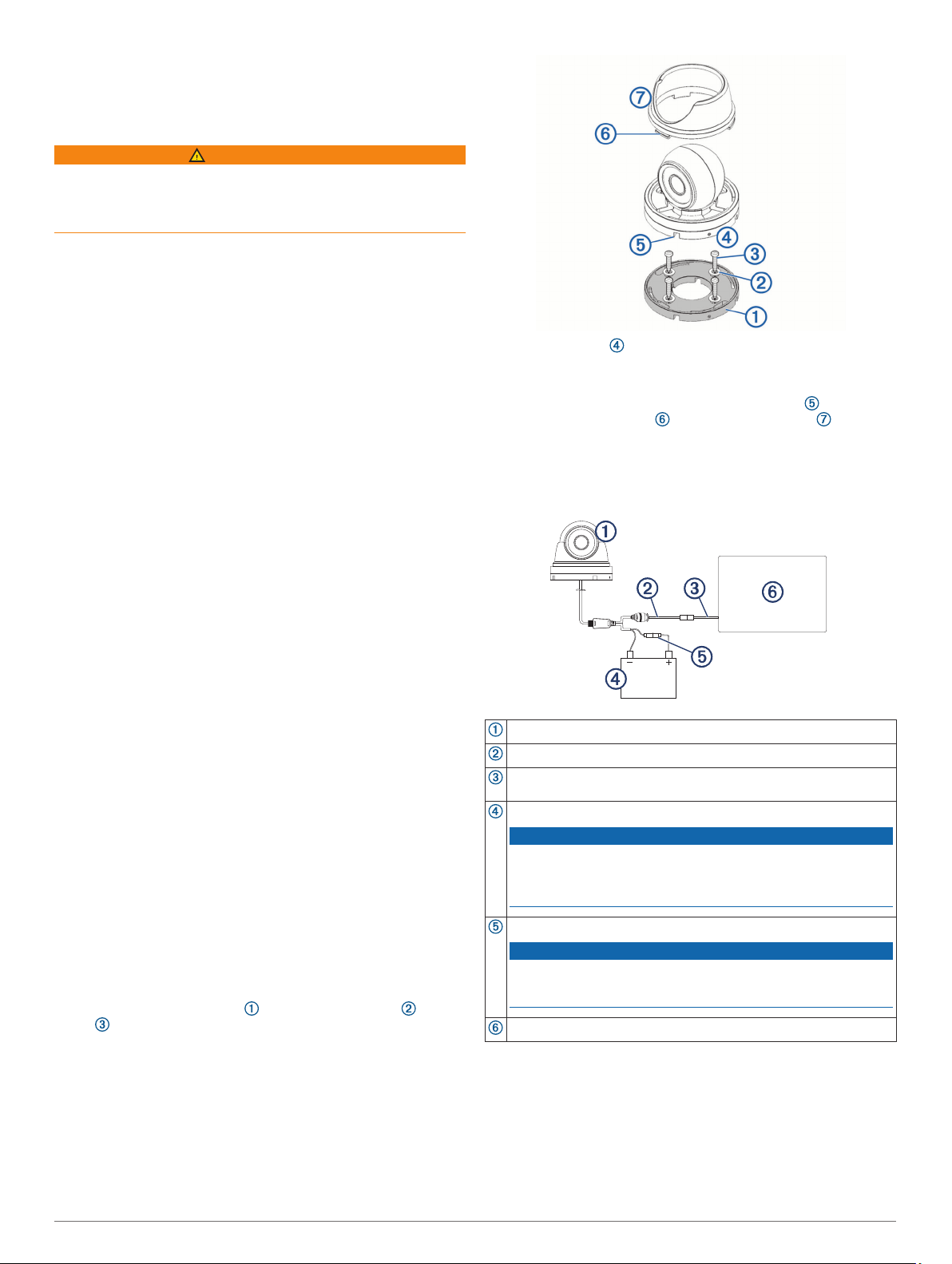
Mounting the Camera
Secure the template to the mounting location.
1
Using a 2 mm (1/16 in.) drill bit, drill the pilot holes.
2
Using the included hex wrench, loosen the screw in the side
3
of the camera base.
Remove the base from the camera body.
4
Feed the camera cables through the camera base, or through
5
one of the cable channels.
Align the camera base with the pilot holes, and secure the
6
camera base with the washers and screws .
Attach the camera to the base, and tighten the screw in
7
the camera base.
Connect the camera cables.
8
Align the slots on the camera base with the collar lugs ,
9
and turn the collar until it locks.
Connection Considerations
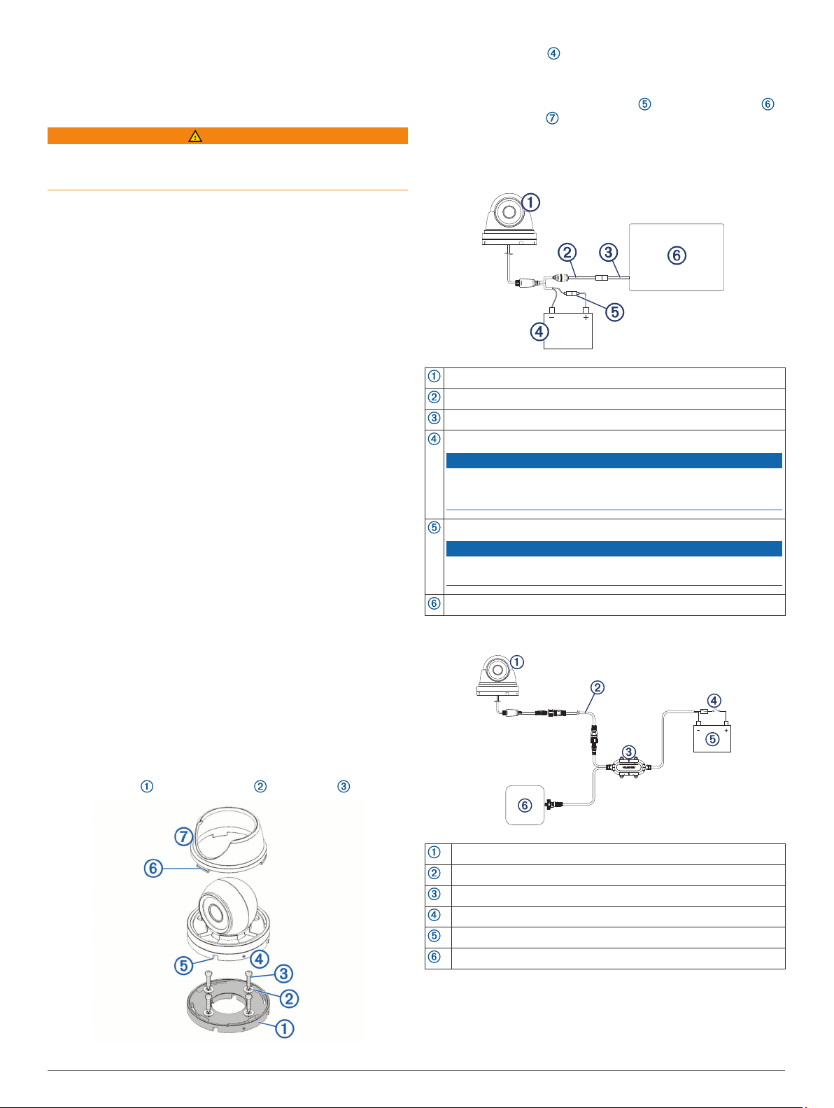
Connection Diagram with Direct Power
GC™ 200 marine IP camera
Garmin Marine Network cable small connector (included)
Garmin Marine Network Adapter Cable small to large (included)
9 to 18 Vdc power source (not included)
NOTICE
To avoid permanently damaging the camera, do not connect the
camera directly to a 24 Vdc system. You must use a Garmin Power
Module when connecting to a 24 Vdc system.
1 A fast-acting fuse (required, not included)
NOTICE
You must connect the power wire through a 1 A fast-acting fuse
(not included). Without a fuse, the device can malfunction.
Garmin chartplotter (not included)
Connection Diagram with a Garmin Power Module
GC 200 marine IP camera
Garmin Marine Network cable small connector
Power module (010-12527-00, not included)
In-line switch (not included)
9 to 32 Vdc power source (not included)
Chartplotter (not included)
2 Installation Instructions

Camera Status LED
LED Activity Status
Solid red The camera is on.
Solid green The camera is connected to the network and
Flashing green The camera detects motion.
transmitting data.
Specifications
Dimensions (Base W x H) 87 x 79 mm (3.4 x 3.1 in.)
Weight 520 g (1.2 lbs.)
Water rating IEC 60529 IPX7
Operating temperature range From -20 to 60°C (from 14 to 140°F)
Storage temperature range From -30 to 60°C (from -4 to 140°F)
Input voltage From 9 to 18 Vdc
Power module input voltage
(not included)
Operating current with infrared on370 mA
From 9 to 32 Vdc
1
Operating current with infrared
off
Power consumption Max 5 W with infrared on
Fuse 1 A fast-acting (required for direct
Horizontal viewing angle 99.2 +/- 3 degrees
Vertical viewing angle 74 +/- 3 degrees
Infrared distance 30 m (98.4 ft.)
Compass-safe distance 10 cm (4 in.)
210 mA
power connection, not included)
1
The device withstands incidental exposure to water of up to 1 m for up to 30 min. For more information, go to
www.garmin.com/waterrating.
Installation Instructions 3
Caméra marine IP GC™ 200
Instructions d'installation
Considérations relatives au montage
AVERTISSEMENT
Consultez le guide Informations importantes sur le produit et la
sécurité inclus dans l'emballage du produit pour prendre
connaissance des avertissements et autres informations
importantes sur le produit.
Vous pouvez installer la caméra à l'envers ou à l'horizontale.
Vous pouvez inverser l'image de la caméra pour obtenir une vue
de derrière. Pour plus d'informations, reportez-vous au manuel
d'utilisation du traceur.
REMARQUE : pour afficher et configurer le flux de la caméra
sur votre traceur, vous devez mettre à jour le logiciel de votre
traceur.
• La caméra doit être installée dans un endroit où elle ne
risque pas d'être immergée et ne présente aucun risque dans
les passages de portes ou les passavants. Tenez-la éloignée
des quais et autres équipements, pour éviter qu'elle ne soit
endommagée.
• Installez la caméra sur une surface capable de supporter son
poids et dans un endroit où vous pouvez la retirer sans
peine.
• Installez la caméra en veillant à pouvoir brancher les câbles
facilement et à ce que le voyant LED soit visible.
• Pour éviter toute interférence avec un compas magnétique,
respectez la distance de sécurité indiquée dans les
caractéristiques techniques du produit.
• Testez la caméra à son emplacement de montage avant de
l'installer de manière définitive.
• Vous pouvez utiliser le module d'alimentation Garmin pour
simplifier l'installation. Avec le module d'alimentation, un
câble de caméra unique remplace le câble d'alimentation et
le câble Ethernet. Cette option est particulièrement
intéressante quand la caméra est située à distance des
autres équipements électroniques, par exemple près de
l'étrave ou sur un mât.
Outils requis
• Perceuse et foret de 2 mm (1/16’’)
• Tournevis Pozidriv
Montage de la caméra
Fixez le modèle sur l'emplacement de montage.
1
A l'aide d'un foret de 2 mm (1/16 po), percez les trous
2
d'implantation.
À l'aide de la clé Allen incluse, desserrez la vis sur le côté de
3
la base de la caméra.
Retirez la base du corps de la caméra.
4
Acheminez les câbles de la caméra à travers la base de la
5
caméra ou à travers l'une des gouttières à câbles.
Alignez la base de la caméra sur les trous d'implantation et
6
fixez la base de la caméra à l'aide des rondelles et des
vis .
Fixez la caméra à la base, puis serrez la vis sur la base de
7
la caméra.
Branchez les câbles de la caméra.
8
Alignez les encoches sur la base de la caméra avec les
9
languettes sur le collier , puis tournez le collier jusqu'à
ce qu'il se verrouille.
Considérations relatives à la connexion
Schéma de branchement avec alimentation directe
GC 200Caméra IP marine GC 200
Câble Garmin Marine Network petit connecteur (inclus)
Câble adaptateur petit à grand pour le réseau Garmin Marine
Network (inclus)
Source d'alimentation de 9 à 18 V c.c. (non incluse)
AVIS
Pour éviter d'endommager la caméra de façon permanente, évitez
de la brancher directement sur un système de 24 V c.c. Utilisez
plutôt un module d'alimentation Garmin quand vous effectuez un
branchement sur un système de 24 V c.c.
Fusible à action rapide 1 A (obligatoire, non inclus)
AVIS
Vous devez connecter le câble d'alimentation via un fusible à action
rapide 1 A (non inclus). S'il manque un fusible, l'appareil ne fonctionnera pas correctement.
Traceur Garmin (non inclus)
4 Instructions d'installation
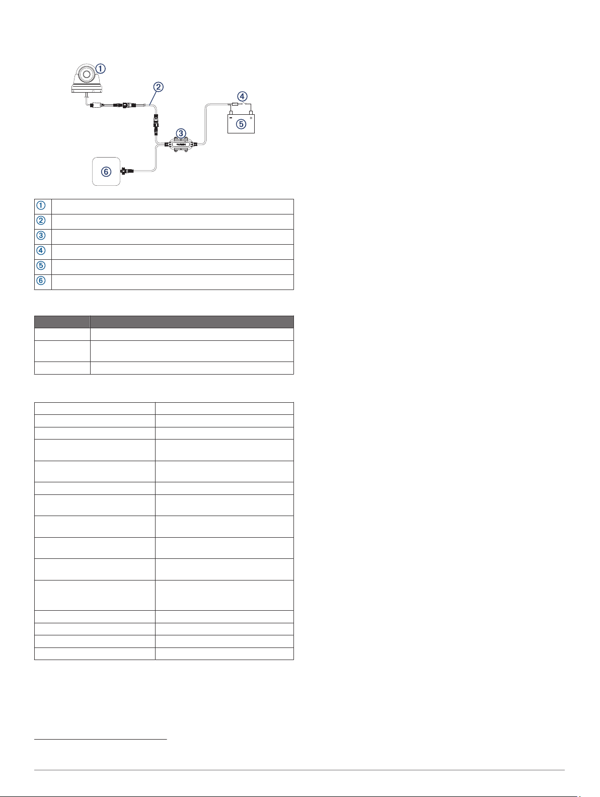
Schéma de branchement avec un module d'alimentation Garmin
GC 200Caméra IP marine GC 200
Câble Garmin Marine Network petit connecteur
Module d'alimentation (010-12527-00 non inclus)
Interrupteur (non inclus)
Source d'alimentation de 9 à 32 V c.c. (non incluse)
Traceur (non inclus)
Voyant LED d'état de la caméra
Activité LED État
Rouge - fixe La caméra est allumée.
Allumé vert La caméra est connectée au réseau et transmet des
Vert clignotant La caméra détecte du mouvement.
données.
Caractéristiques
Dimensions (Base L x H) 87 x 79 mm (3,4 x 3,1 po)
Poids 520 g (1,2 lb)
Résistance à l'eau IEC 60529 IPX7
Plage de températures de fonc-
tionnement
Plage de températures de
stockage
Alimentation De 9 à 18 V c.c.
Tension d'entrée du module
d'alimentation (non inclus)
Tension de fonctionnement avec
l'infrarouge activé
Tension de fonctionnement avec
l'infrarouge désactivé
Consommation électrique 5 watts maximum avec l'infrarouge
Fusible 1 fusible rapide 1 A (obligatoire pour
Angle de vue horizontal 99,2 +/- 3 degrés
Angle de vue vertical 74 +/- 3 degrés
Distance infrarouge 30 m (98,4 ft)
Distance de sécurité du compas 10 cm (4 po)
De -20 à 60°C (de 14 à 140°F)
De -30 à 60°C (de -4 à 140°F)
De 9 à 32 V c.c.
370 mA
210 mA
activé
un branchement direct sur l'alimentation, non inclus)
2
2
L'appareil résiste à une immersion accidentelle dans un mètre d'eau pendant 30 minutes. Pour plus d'informations, rendezvous sur www.garmin.com/waterrating.
Instructions d'installation 5

Videocamera per la nautica GC™ 200
IP
Istruzioni di installazione
Informazioni sull'installazione
AVVERTENZA
Se guiden Vigtige oplysninger om sikkerhed og produkter i
æsken med produktet for at se produktadvarsler og andre
vigtige oplysninger.
È possibile montare la videocamera in posizione capovolta o
lateralmente. È possibile invertire l'immagine della videocamera
da utilizzare in modalità retrovisore. Per istruzioni, consultare il
Manuale Utente del chartplotter.
NOTA: è necessario aggiornare il software del chartplotter per
configurare e visualizzare i feed della videocamera sul
chartplotter.
• È necessario montare la videocamera in una posizione in cui
non sia sommersa, non presenti alcun pericolo nelle porte o
nei punti di passaggio e in cui non possa essere danneggiata
da banchine, piloni o altre strutture.
• Montare la videocamera in una posizione sufficientemente
solida da supportare il peso del dispositivo e in cui sia
possibile rimuoverla.
• Montare la videocamera affinché il LED sia visibile e sia
possibile collegare i cavi con facilità.
• Per evitare interferenze con una bussola magnetica, montare
la videocamera rispettando la distanza di sicurezza dalla
bussola indicata nelle specifiche del prodotto.
• È necessario testare la videocamera nella posizione
selezionata prima di installare definitivamente la
videocamera.
• È possibile utilizzare il modulo di alimentazione Garmin per
semplificare l'installazione. Il modulo di alimentazione utilizza
un unico cavo per videocamera anziché cavi separati di
alimentazione ed Ethernet. Ciò è particolarmente utile
quando la videocamera è posizionata lontano da altri
strumenti elettronici, ad esempio vicino alla prua o su un
albero.
Strumenti necessari per l'installazione
• Un trapano e una punta da trapano da 2 mm (1/16 poll.)
• Cacciavite Pozidriv
Installazione della videocamera
Fissare la dima nella posizione di installazione selezionata.
1
Con una punta da trapano da 2 mm (1/16 poll.), praticare i fori
2
di riferimento.
Usando la chiave a brugola in dotazione, allentare la vite su
3
lato della base della videocamera.
Rimuovere la base dal corpo della videocamera.
4
Passare i cavi della videocamera nella relativa base o in una
5
delle canaline dei cavi.
Allineare la base della videocamera ai fori di riferimento,
6
quindi fissare la base della videocamera con le rondelle
e le viti .
Collegare la videocamera alla base e serrare la vite nella
7
base.
Collegare i cavi della videocamera.
8
Allineare le scanalature sulla base della videocamera ai
9
fermi del collare e ruotare il collare finché non si blocca.
Informazioni sul collegamento
Schema di collegamento con alimentazione diretta
Videocamera IP per la nautica GC 200
Connettore piccolo del cavo Garmin Marine network (incluso)
Cavo adattatore Garmin Marine Network da piccolo a grande
(incluso)
Fonte di alimentazione da 9 o 18 V cc (non inclusa)
AVVISO
Per evitare danni permanenti alla videocamera, non collegare la
videocamera direttamente a un sistema a 24 V cc. È necessario
utilizzare un modulo di alimentazione Garmin per il collegamento a
un sistema a 24 V cc.
Fusibile ad azione rapida da 1 A (necessario, non incluso)
AVVISO
È necessario collegare il cavo di alimentazione tramite un fusibile
ad azione rapida da 1 A (non incluso). Senza un fusibile, il prodotto
potrebbe essere soggetto a malfunzionamenti.
Chartplotter Garmin (non incluso)
6 Istruzioni di installazione
 Loading...