

Page 1
Futaba
DIGITAL PROPORTIONAL
RADIO CONTROL
PCM
SINGLE STICK
PULSE CODE MODULATION SYSTEM
Page 2

Thank you for purchasing a Futaba
digital proportional radio control set
Please read this manual carefully before using your set.
The names and functions of the transmitter controls can be easily understood
by
reading this section with the three-fold page at the end of this manual unfolded.
Page 3

TABLE OF CONTENTS INDEX FOR TRIMMER PANEL FUNCTIONS
1
GENERAL INFORMATION
Features
............................
Contents and Ratings
Glossary of Terms
Basic
Transmitter
Batteries and Charging
Tachometer/Timer Operation
Receiver
and
Controls
Instructions
Servos
.....................
...................
......................
..................6~9
.............
................
.2~3
10~11
.12~14
ADJUSTMENTS AND FLIGHT TECHNIQUES
Basic
Linkages and
Using ATV (Adjustable Travel
2ND
ATV
Servo
Reversing
Using Dual Rate (Aileron, Elevator, and Rudder) . . . .
Automatic
Using VT R (Variable Trace Ratio)
Suggestions
Using ATL (Adjustable
FS (Fail Safe) and HOLD Functions ............
BFS (Battery Fail
Servo
Test
Aircraft
with
Throttle
Position
Aircraft
with
Elevator/Flap
Flap/Elevator Mixing (Pro-Set Flaps and Etev. Trim). . . .30
Aircraft
with
Flap
Trim
Snap
Roll
Programmable
Mutual (Bi-directional) Mixing (FLPRON,
ELEVN,
V-TAIL,
FP-S130and
Transmitter
Splined Horns
Installation
(Conventional)
Switches
Dual Rate
on
ATV,
D/R,
Safe)
Functions
Function
Switch
.....................
Variable
Trimmer
Flaps
......................
Mixing
....................
Flaps and Spoilers
.....................
.......................
Mixing
DIFF)
FP-S130G
Controls
..........................40
...............
Volume)
..................
..................
on
Rudder
..............
.............
and VT R
Throttle
Limit)
and BFS
Memory
Pitch
Prop
.............
.................
(Airbrake)
and
Examples.
..................
Exploded Views
..................... .
..........
............
..........
........
........
...........
.........
.16
. 19
.
.23
.24
.25
.25
.26~27
.28
.29
.30)
.32
.32~33
.34~36
.4
.5~6
.15
.17~18
. 19
. 20
21
. 21
.22
.29
.31
.37
38 39
Switch or Description Ref. Page
Trimmer
Number
1 Aileron Dual Rate 1 Trimmer .............20
2
Aileron
Dual Rate 2 Trimmer
3
Aileron
Linear/VTR Safety
4
Throttle
Delay
5
Pitch
6
Throttle/Pitch
7
Throttle/Pitch
8
Throttle
9
Elevator Flap
10
Elevator Flap
11 & 12 Programmable Mixing Rate Trimmers ..... .32 33
Slave
13
14 Master Channel Mixing
15 Aileron Differential
16 ELEVN/V. Tail
17 FLPRON/DIFF
18 Flap
Switch
19 Airbrake Elevator
20
Airbrake Flap
21
Rudder Dual
22 Rudder Linear/VTR Safety
23 Elevator Dual Rate
24 Elevator Linear/VTR Safety
25-28 Snap Roll Timer Setting Trimmers (Optional) . • .32
29 Snap
30
Switch
31 Automatic Dual Rate Rudder Safety
32 Flap, Spoiler Elevator
33 Throttle Flap, Spoiler Elevator Mixing Switch . . . . .31
34-35
Aileron
36 37 Elevator
38-45 Servo
46-47 ATV/FS
48 Channel Select
49
Function Select Switch
Trimmer
Delay
Trimmer
Mixing
Mixing
Position
Trimmer
Mixing
Mixing
Channel
Mixing
Trimmer
Mixing
Mixing
........................
Trimmer
Trimmer
Rate
Trimmer
Trimmer
Roll
Safety Switch
16
Function
2ND
ATV Trimmers
2ND
ATV
Reversing
Switches
Buttons
Switch
..............
Switch
.................
...................
Trimmer
Safety
Trimmer
Safety
Board
Board
Switch
Switch
.................
..................
Select
Mixing
Trimmer
...................
.................. .18
.................
..........
.............
Switch
..........
...............
.............
Switch
..........
..............
............... 32 33
..............
.............
.............
...............
...............
Switch
..........
..............
Switch
..........
Switch
............
Switch
Switch
............
............
..............
......
.........
.20
.20
.26
.26
.26
.26
.26
.29
.29
.32
.34~36
.35~36
.34~36
.31
.30)
.30)
.20
.20
.20
.20
32
21
21
.30
.19
.19
.19
.17
.18
27
27
27
27
28
33
23~25
23~25
23~25
NOTE:
Please read and follow instructions for installation and usage in their entirety and
follow carefully. Failure to follow instructions could result in serious property
damage and/or personal injury. This system is intended for use by exp erie nced
R/C hobbyists. Beginners should seek expert advice and Assistance before operating this system.
Page 4

•FEATURES
The FP-8SSAP was specially developed to use PCM (pulse code modulation) for FAI
RC aerobatics F3A aircraft. It is an extremely noise and dead-point resistant digital
proportional RC set with a microprocessor in the transmitter and the receiver. Please
read this manual before using your set.
TRANSMITTER FP-T8SSAP
•Pitch
• RF module system. The frequency band can be
changed with one touch.
• DSC (Direct Servo Controller) allows operation
of the servos without turning on the transmitter.
Wire operation is possible by using the special
cord supplied (FSC.1).
•Servo reversing switch for all channels allows
reversing
• Dual rate or non-linear VTR (variable trace
ratio) aileron, elevator, and rudder. Two-stage
dual rate on aileron.
• Rudder auto dual rate. Rudder dual rate is
2
turned on and o ff automatically with operation
of the throttle lever.
• Newly designed rotatable open gimbal stick
provide maximum operation feel. Stick position
and spring tension c an be adjusted.
• New throttle -> pitch control mixing is perfect
for variable pitch propeller which maximizes
engine power and propeller efficiency.
• Mutual m ix ing function allows aileron + elevator, aileron + flaps, and aileron + rudder mixing
and aileron differential operation.
• Elevator -> flap mixing is especially advantageous
in circle aerobatics.
• Flap, spoiler -> elevator mixing allows control of
the aircraft attitude while using the air brake
(flap, spoiler).
• Throttle -> (flap, spoiler) -> elevator mixing
allows enhancement of the air braking effect by
throttle lever operation when div in g and landing.
• Programmable mixing function permits mixing
with the desired channel.
• Four-function snap roll switch (Timer is op-
tional).
• Idle-up lever, the engine idling speed can be
independently adjusted during throttle -> pitch
control mixing.
• New single-chip microprocessor allows one-touch
fail safe setting and introduction of an automatic
transmission system which eliminates the need
for fail safe setting at the beginning of each
flight and improves safety.
of the
servos
with
the
flip
of a switch.
•Trainer
control
pitch propeller can be adjusted during throttle
-> pitch control mixing.
• New ATV (Adjustable Travel Volume) on all
channels allows independent adjustment of servo
left, right, up, and down throw.
• Second A TV. Besides new pushbutton ATV on
aileron and elevator, conventional trimmer ATV
is also installed.
• Monitor lamp comes on when throttle -> flap,
spoiler -> elevator mixing or throttle -> pitch
control mixing and flap, spoiler -> elevator mixing and snap roll are set and goes out when they
are
in
use.
• Fail-safe switch (function OFF switch) is provided for each function so that only the desired
functions need be turned
•Throttle ATL (Adjustable Throttle Limiter)
makes throttle linkage simple and positive.
• Two servo test functions. A slow sweep to check
neutral characteristic, trackability cycle servo to
test servo operation.
•Tachometer/timer with built-in tachometer, up
timer, down timer, integrating timers, and battery alarm functions.
• Built-in power error back-up circuit. When the
internal Nicd battery approaches the fully dis-
charged state, an LED flashes to indicate that
the memories presetted (memory, ATV, FS,
etc.) are gone. Please charge battery and set all
memory functions again.
•
Highest quality anodized
sophisticated transmitter design gives easy comfortable feeling to your hands.
for beginners.
system
lever.
offers
HIGH
an
side
pitch
on.
aluminum
easy
training
of
variable
case
of
with
flight
Page 5

RECEIVER FP-R118GP
3
•The
receiver
ceiver in which the highest reliability has been
pursued. It is the first R/C receiver in the world
to incorporate the newest computer technology.
• Miniature PCM receiver with high speed single
microprocessor. Resistance to adjacent band and
spark noise interference has been increased by
one full order of magnitude.
• Microprocessor servo hold function eliminates
erroneous
is entered.
• Microprocessor provides fail safe and battery fail
safe functions for greater safety.
• Error lamp display allows checking of the receiver operating state.
of this
operation
set
is a miniature
when a "dead
PCM
point"
re-
area
SERVO FP-S130
•Small, double ball bearing, water-tight & dusttight servo. High output torque 55.6 oz-in (5kgcm), high-speed .24sec/60°.
• New indirect drive potentiometer improves
vibration and shock resistance and neutral
precision.
• Futaba low-power custom 1C provides high starting torque, narrow dead band, and excellent
trackability.
• Fiberglass reinforced PBT (polybutylene terephthalate) molded servo case is mechanically
strong and invulnerable to glow fuel.
• DC-DC converter in the power supply improves
low-voltage operation characteristics.
• High sensitivity design with RF amplifier.
• Ultra narrow-band ceramic filter and PCM system are invulnerable to adjacent band interference.
• Gold plated connector pins eliminate poor con-
tact. Polarized housing improves reliability
against shock and vibration.
• DSC circuit. Each servo can be controlled from
the transmitter without turning on the transmitter by connecting the transmitter directly to the
C terminal.
• Strong polyacetal resin ultra-precision servo gear
features smooth operation, positive neutral, and
very little backlash.
•
Fiberglass
thru-the-hole plating improves servo amp vi bra tion and shock resistance.
•Thick
contact and improve reliability against shock and
vibration. The connector housing is polarized to
prevent reverse insertion.
• Six special adjustable splined horns.
reinforced epoxy
gold plated connector pins ensure positive
resin
PC
board
with
SERVO FP-S130G
•Small
retractable landing
class 5-pole micromotor. High output torque
4.7kg-cm, high-speed 0.34sec/60°, waterproof
type.
•Since forward/reverse operation is controlled by
the pulse width of the signal generated by turning the transmitter snap switch on and off, the
motor stops at the end of its throw in either
direction.
• Unlike other proportional servos, motor drive
current does not flow when the servo is stopped
even if a load is applied. Thus current drain is
extremely low.
gear
servo
with
high
• Fiberglass reinforced PBT (polybutylene terephthalate) injection molded servo case is mechanically strong and invulnerable to glow fuel.
•Strong
•
• Thick gold plated connector pins ensure positive
polyacetal
features smooth operation, positive neutral, and
very little backlash.
Fiberglass
thru-the-hole plating improves servo amp vibration
contact and improve reliability against shock and
vibration. The connector housing is polarized to
prevent reverse insertion.
reinforced epoxy resinPCboard
and shock
resin
ultra-precision
resistance.
servo
gear
with
Page 6

•CONTENTS AND RATINGS
Ratings and specifications are subject to change without prior notice.
Model
Transmitter
Receiver
Servos
Switch
Nicd battery
Accessories
Transmitter FP-T8SSAP
Operating system
Transmitting
frequency
4
Modulation
Power requirement
Current drain
Battery charger, landing gear adaptor, DSC cord, CHG adaptor, DSC-CHG cord,
servo tray, frequency flag, spare horn, screws
Receiver FP-R118GP
Single-stick, 8 channels for
F3A pattern
50/53MHz BANDS
72/75MHz BANDS
53MHz ~ 72MHz
Frequency change to any of
above bands is possible by
merely changing RF module.
PCM,FM
9.6V 8/500mAH internal
Nicd battery
250mA
FP-8SSAP
FP-T8SSAP x 1 with module FP-TF-FM
FP-R118GPx 1
FP-S130x4
SWH-5x 1 (R4-SWJx1»
NR-4Jx1
Receiving frequency
Chosen
band
Intermediate
frequency
Power requirement
Current drain
Dimensions
Weight
Receiving range
50/53MHz BANDS [chosen
72/75MHz BANDS (band
455kHz
4.8V Nicd battery (shared
with servo)
42mA (4.8V reception)
2.23 x 1.65x0.94 in
(57 x 52 x 24mm)
1.85oz (53g)
500m on the ground
1000m in the air
When FP-T8SSAP used.
(At the best radio wave con-
dition of environment)
Servo FP-S130 Landing Gear Servo FP-S130G (Option)
Control system
Operating angle
Power requirement
Current drain
Output torque
Operating speed
Dimensions
Weight
+pulse width control,
uS.N
One side 45° or greater
including trim)
4.8V
(shared
5mA (at idle)
55.6oz.in (4kg-cm)
0.24 sec/60°
1.52
x
(38.5 x 19.5x34.5mm)
1.47oz(42g)
with receiver)
0.77 x 1.36 in
1520
in-
Control system
Operating angle
Power requirement
Current drain
Output torque
Operating speed
Dimensions
Weight
+pulse width control
Rotary approx 160°
4.8V
(shared
8mA (at idle)
65.3oz.in (4.7kg-cm)
0.34 sec/60°
1.52x0.77x 1.36 in
(38.5 x 19.5x34.5mm)
1.48oz (42g)
with
receiver)
Battery Charger FBC-8B(2) Receiver Servo Nicd Battery NR-4J
Input voltage
Output
: 120VAC,50/60Hz
: TX side 9.6V/45mA
:RX
side 4.8V/45mA
Voltage
Dimensions
Weight
: 4.8V, 4/500mAH
:
2.01 x 2.28 x 0.59
(51 x 58 x 15mm)
: 3.35oz (95g)
in
Page 7

GLOSSARY OF TERMS
NOTE: Please take the time to familiarize yourself with the terms and abbreviations
below. They will be used throughout the instructions and are important in understanding the operation and potential of your system.
PCM (Pulse Code Modulation) SERVO REVERSING
Pulse Code Modulation utilizes a precise digital
code to convey information from the transmitter
encoder to the receiver. This state of the art method makes many of the sophisticated functions of
the FP-8SSAP possible, as well as providing far
superior immunity to noise and interference than
is possible with conventional encoding methods.
ATV (Adjustable Travel Volume)
This feature allows independent adjustment of
servo travel in each direction. ATV is sometimes
referred to as "endpoint adjustment". Two dif-
ferent types of ATV are standard with this system,
(1) Pushbutton or Programmed (Memory) ATV
and (2) 2nd ATV (Conventional).
MEMORY ATV
This type is available on all eight channels. These
adjustments are stored in the transmitter memory
circuit and are retained when the power switch is
turned OFF. They are lost however, if the trans-
mitter Nicd batteries reach full discharge.
2ND
ATV
Available on Aileron (CH 1) and Elevator (CH 2).
This is the conventional type ATV which is set by
using trimmer pots on the transmitter back panel.
These settings are NOT affected if the transmitter
batteries are discharged.
DUAL RATE
Rate switches allow the pilot to select different
servo travel limits (for varying control sensitivity)
in flight. Servo travel is affected equally in both
directions from center.
SAFETY (ACT/INHIB)
These switches, located on the transmitter trimmer
panel allow mixing and certain other functions to
be deactivated when not desired. When the Safety
Switches are set to the INHIB position, the function will remain OFF even if the transmitter control switch is set to ON.
VTR (VARIABLE TRACE RATIO)
This is a special type of non-linear control response. When VT R is used, servo travel is normal
and linear up to about 80 percent of the transmit-
ter control stick movement where the servo travel
is abruptly increased to a higher rate (both rates
adjustable). This allows a normal feel f or most fly-
ing with extra movement available for emergencies
and certain acrobatic maneuvers. Another way to
think of this function is as "automatic Dual Rate".
SWITCHES
This function allows the modeler to reverse the
direction of servo movement (in relation to control stick movement) for various installation requirements. This can be done by conveniently
flipping a switch on the trimmer panel. Servo
travel and neutral position are not affected.
The
Safe)
throttle
to
set
elevens
Limit)
trim
lever
the proper idle
on
tailless
BFS (Battery Fail
This function provides a warning to the flyer when
airborne battery voltage reaches a critically low
level by moving the throttle se rvo to medium slow
or slow position.
ATL (Adjustable Throttle
This feature makes adjusting the throttle linkage
easier.
much
the LOW or IDLE position and not the HIGH
throttle servo position. Therefore, the linkage can
be set for proper opening at high throttle and the
trim
lever
used
out changing the maximum opening.
MIXING
In
general, mixing functions allow two or more
different channels to be operated by moving a
single transmitter control. Many useful and versatile functions are made possible in this manner.
Three types of mixing functions are provided.
(1) Unidirectional mixing — This function allows
one or more channels to be "slaved" to a "master"
channel. Movement of the master channel control
causes movement of both master and sl aved servos
simultaneously. Operation of the slave channel
control however, does not cause movement of the
master channel servo. An example is Aileron/Rudder mixing (see page 3 3) wh ere the Rudder is
slaved to Ailerons for coordinated turns.
(2) Mutual (Bi-Directional) Mixing - With this
type of mixing, two channels are mixed so that
operation of the control for either channel causes
movement of both servos. This is useful in providing sophisticated functions such as V-tail operation,
flaprons, and
(3) Switch-Activated Mixing — Two or more-
channels can be programmed so that the servos
involved move to a preset position when a trans-
mitter control switch is pulled or button pushed.
Snap roll switches, roll buttons, and pre-set
switches are examples of this type of mixing.
affects
speed
designs.
only
with-
5
flap
Page 8

PROGRAMMED MIXING FAIL SAFE
Unidirectional mixing of any two channels desired
is possible using the pin board and jumper connectors on the transmitter back panel. Either channel may be designated as "master" or "slave".
DSC
(Direct
Servo
Control)
Operation of the entire system with the transmitter switch in OFF position is possible using the
DSC cord. This is useful for checking and adjusting
control movements on the ground while someone
else is flying on your frequency.
The Fail Safe function moves servos to a pre-set
position if the transmitter signal is lost or interrupted by strong interferrence. The servos will be
held in the pre-set position until a proper signal is
again received at which time Fail Safe is released.
HOLD
The Hold function holds servos at the same position
as
immediately prior
Hol d is released when a proper signal is resumed.
•Trainer system offers an easy training of flight
for beginners.
to
signal
•BASIC TRANSMITTER CONTROLS
The servo reversing switches are assumed to be in the normal position in the descriptions in this section. When the reversing switches are in the reverse position, servo
operation is the opposite of that described here.
interruption.
6
The names and functions of the transmitter
controls can be easily understood by reading this section wit h th e three-fold page at
the end of this manual unfolded.
1
Aileron stick
2
Elevator stick
3
Throttle
4
Rudder knob
5 Landing gear switch Controls the landing gear.
6 Flap and flap trim control (CH6) knob
7 Spoiler (CH7) control knob
8 Pitch control (CH8) lever and pitch control
HIGH side trimmer
9 Idle-up lever
10 Flap, spoiler -> elevator (6, 7 -> 2) mixing
OFF switch
11 Throttle -> (flap. spoiler) -> elevator
2) mixing / Throttle -> pitch control mixing
ON-OFF switch
Elevator -> flap
12
13 Snap Roll ON-OFF switch (self
Controls the ailerons.
Controls the elevators.
lever
Controls the
Controls the rudder.
(2 -> 6) mixing ON-OFF switch
throttle.
(3 — 6. 7 ->
off)
ON-
1 4 Aileron dual rate switch (2-stage)
15 Elevator dual rate switch
16 Rudder dual rate/Programmable mixing ON-
OFF switch
17 Aileron trim lever
18 Elevator trim lever
19 Throttle trim lever with ATL
20 Rudder trim lever
21 Tachometer/timer
The tachometer/timer has the following functions:
1. TACHOMETER
• Measurement by external sensor
• Two blade propeller specifications
• LOW range 100 to 30,000 rpm
Error 100 rpm
•HIGH
2. UP
• 0 to 60 minutes with seconds display
3. DOWN TIMER
• 60 to 0 minutes with seconds display
4. INTEGRATING TIMER
• 0 to 60 hours with minutes displ a y
5. BATTERY ALARM
• Alarm sounds when the transmitter Nicd
range
100
TIMER
batteries approach the
to
Error 200 rpm
60,000
usage
rpm
limit.
Page 9
22 Monitor Lamps
7
IMPORTANT: In all instructions on control functions. Items designated by a number inside a circle
(For example 10 ) are transmitter controls normally accessable and operated in flight.
Items designated by a number within a box (For example 10 ) are adjustment functions not operated
while in flight.
Lamp A Power Monitor
• When the power switch
briefly and then goes out momentarily as the Fail Safe data is automatically matically transmitted to the receiver. Fail Safe data is
transmitted every 60 seconds at which time the lamp al so goes out
momentarily. If the transmitter Nicd battery nears full discharge,
this lamp starts blinking, indicating that the power error backup
function is activated. When this occurs, transmitter memory function settings are lost and must be reset.
23 is set to ON, this lamp flashes on
LampB3 -> 6. 7 -> 2 I 3 -> 8 Mix
This lamp comes on when Safety Switch 7 and/or [33] is set to
ACT position, indicating that throttle —-> flap, spoiler —-> elevator
mixing and/or throttle -> pitch control mixing functions are activated. This lamp will blink when transmitter control switch II is set
to ON (placing these functions in operation).
Lamp C 6, 7 -> 2 Mix
• This lamp comes on when Safety Switch [32] is set to ON (flap,
spoiler -> elevator mix) or CH7 OFF (flap -> elevator mix) position.
This lamp blinks when transmitter control switch 10 is set to ON.
Fig.1
When the power switch 23 is set to ON, lamp (A) will go out momentarily. This indicates automatic data
transmission on and is not a failure.
23 Power switch
• The transmitter power ON-OFF switch is provided with a locking feature to prevent accidental movement. To operate the switch, pull the
knob gently outwards and set to the desired
position (UP=ON. DOWN=OFF).
25 Level meter
• This meter indicates the transmitter battery
voltage and output power.
•W hen the antenna 26 is extended fully and
the power switch 23 is set to ON, the pointer
should move to the white zone.
•If the transmitter RF Module
32 is not
stalled, the meter pointer will not move.
• If the meter pointer moves to the red zone,
indicating that the Nicd battery voltage is low,
the
signal
range
will
become
shorter.
Tachometer/timer 2 1 power switch is ON, the
Lamp D Snap Roll
• When Safety Switch [29] is set to ACT (snap roll function activated), this lamp blinks. When the Snap Roll switch 13 is pulled,
this lamp continues blinking.
26 Antenna
Strong 1m 10cm telescoping antenna. Extend
the antenna to its full height when using the
transmitter. The antenna will lock in place with
a click when pulled up to its ful l height.
27 Carrying handle
28 Tachometer sensor connector
•When not using t his connector and the charging socket 29, cover them with the rubberbacked cover supplied to protect them against
dust.
in-
29 Charging socket and DSC (Direct Servo Con-
troller) connector
• This connector is used as both the charging
If
the
socket and DSC connector. See
charging instructions.
page 10 for
battery alarm function will operate after about
one more flight. When the meter pointer stops
at the boundary between the white and red
zones, recharge the battery.
Page 10
32 Transmitter RF module
• Change this module when switching frequency bands (50, 53, 72, and 75MHz).
While pushing this tab to the
inside, pull the RF module
forward.
Transmitter crystal
A temperature rise
at the R F module
section during use
is normal.
Fig.
34 Snap roll direction switch (R/L)
35 Snap roll direction switch (UP/DOWN)
•These switches control the direction of the
snap roll when the Snap roll switch 13 is used.
36 Fail safe set button
• This pushbutton is used when setting the Fail
Safe servo positions (FS instructions Page 24).
37 Back Cover
• Removal of this cover exposes
panel. Remove as shown in Fig. 3.
Remove the back cover by pulling
these stoppers in the arrow direction.
the trimmer
Fig.
3
2
8
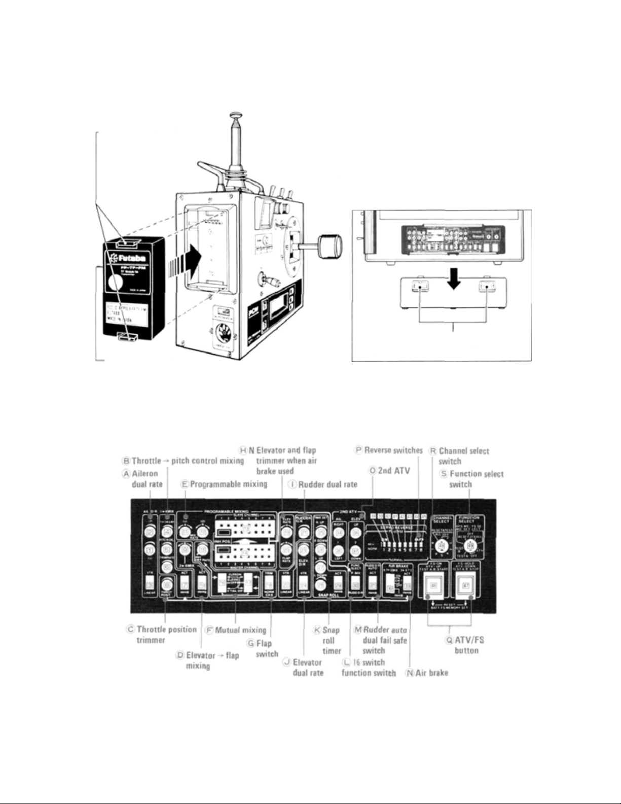
38 Trimmer Panel
•This
panel contains switches,
transmitter functions. Use the small screwdriver supplied with the set for making adjustments.
Use the transmitter with fail-safe switches [7], [10], [29], [31], [32], and [33] in the INHIB (function off)
position until you become familiar with the set.
buttons,
and trimmers
for
setting and adjusting the many
versatile
Fig.
4
39 Trainer cord socket
Page 11
40 Trainer switch
9
Pull on/self-off switch. The transmitter connected by the trainer cord (M-TC) operates and when
it is OFF, your-own transmitter only operates.
• Trainer
Connect the transmitters with the trainer cord
(M-TC-FM, purchased separately) as shown in
Fig.5. When the switch is in the ON (pull) position,
the
student's
when the switch is in the OFF position, the
instructor's transmitter operates. The transmitter at which the trainer switch is operated onoff becomes the instructor's.
transmitter
operates
and
Fig.
5
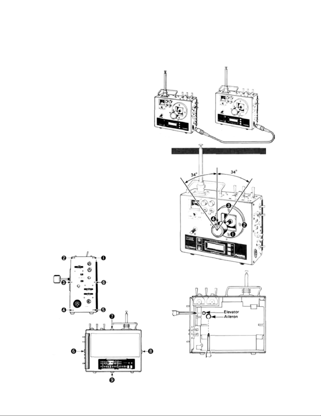
(Power switch ON and transmitter operating)
Instructor transmitter
• Rotative open gimbal stick
• Rotative open gimbal stick allows setting of the
operating direction of the stick within a range of
±34 degrees by losening screws I to 4 in the
figure 1/2 turn and turning the stick grille.
• Set the stick in the direction in which operation
is easiest.
• After setting, retighten the screws.
• The new gimbal is open. This one has been used
only for the most expensive radio controls. It
also has the built-in tension adjustment mech-
anism on open gimbal for the first time. You can
adjust tension of spring for your best stick
feeling.
• Remove the rear panel and right side panel and
adjust the spring tension.
Right side panel mounting screw
Remove these
screws, and
remove the longer
back cover.
Common screw
Student transmitter
(Power switch always OFF)
Fig.
Fig.
6
8
Rear panel Mounting screw
Common
screw
Fig. 7
Turn with a Phillips screwdriver.
The spring tension can be adjusted as desired
by removing the transmitter longer back cover
and turning the adjusting screw of each stick.
Adjust the spring tension for the best stick feel.
Page 12
•BATTERIES AND CHARGING INSTRUCTIONS
AC-120V
Battery charger
FBC-8B (2)
LED
Antenna
10
Receiver
R4-SWJ
Female
Female
Male
Female
Install the accessory
DSC.CHG cord
(connector with tab)
to the side of the
aircraft fuselage to
use the charging/DSC
socket.
DSC.CHG
cord
Female
Male
Fig.
9
Page 13
DSC cord
29
Charging socket
and DCS connector
Male
Female
CHG
Adaptor
Female
Male
Notes:
(1) F irst,
(2) Then, connect to RX Nicd after connecting
(3) In case of separate charging, L.E.D,
connect to TX N icd and red lamp goes
on.
L.E.D, changes color from red to greenish
red (orange) which indicates that both T X
and RX Nicds are being charged.
will be:
RX Nicd-Green TX Nicd - Red
Make.this
connection when
using the DSC.
color
•The
Direct
Servo
Controller
system
connects
the signals from the transmitter directly to
terminal C of the receiver through a wire and
controls the
without
radiating
radio-
servos
waves. It is extremely convenient when flying
on the sam e band or during meets, etc.
• Make the connections shown in Fig. 9. Connecting the
receiver terminal C and installing it to the
special
DSC.CHG cord
with
tab
to
side
of the aircraft fuselage is very convenient.
•When the DIN connector of the DSC cord is
connected to the DSC connector 29, the
power to the encoder inside the transmitter is
turned on. The transmitter power switch is
OFF.
• When not using the DSC, disconnect the DIN
connector.
• To operate the servos, turn on the receiver
and servo switch.
Before using your
as follows:
teries
system, recharge the Nicd bat-
•Connect the DIN connector of the FBC-8B (2)
battery charger to the transmitter charging
socket 29. Also connect the 3P connector to
the airborne NR-4J Nicd battery and plug the
battery charger into a 120VAC outlet as shown
in Fig. 9. The airborne batteries can also be
charged through the DSC/CHG harness by connecting the CHG adaptor to the charger as
shown in Fig. 9. In this manner, the airborne
batteries can be charged without removing them
fr om the model.
•Normally recharge the battery for about 15
hours. If it has not been used for some time,
discharge and recharge it two or three times and
then charge it a full 15 hours.
• The amount of time remaining before the batteries must be recharged can be estimated
using the Integrating Timer function of the
Tachometer/Timer
21. It
is recommended
that thi s function be used to monitor remaining flying time. (See Page 12 for detailed
instructions.)
•The
transmitter
and
receiver
Nicd batteries
can
be charged together or independently.
•A fully-charged transmitter battery can be used
for about 10 flights of 10 minutes each. The
airborne NR-4J Nicd battery can be used for
about 6 flights when 6 servos are used and about
4 flights when 10 servos are used.
• If the system is not to be used fo r some time, it
should be fully charged before storage and
recharged monthly to avoid full discharge and
loss of memory settings (ATV, FS, BFS memory,
etc.).
Page 14
•TACHOMETER/TIMER OPERATION
NOMENCLATURE AND FUNCTIONS
REV. RANGE SW
Switches the range when used as a
tachometer. LOW -100 t o 30,000 rpm.
HIGH -100 to 60,000 rpm
LIQUID CRYSTAL DISPLAY
Fig.
10
Do not press the keys too quickly.
Press them at a speed of about once
per second. |
12
POWERSW
Tachometer/timer power switch.
MODE DISPLAY
< is displayed at the mode selected at
the MODE SEL key switch.
INTEGRATING TIMER
Blinks during counting
and stops blinking when
counting stops.
UP TIMER
DOWN TIMER
TACHOMETER
Selects the tachometer/timer mode.
The INTEGRATING TIMER mode is selected and
is displayed when t h e power is turned on.
The first time this switch is pressed, the UP TIMER
mode is selected and
The
second time it is pressed, the DOWN
mode is selected and
The
third
time
it
is
pressed,
mode is selected and
The fourth time this switch is pressed, the
tachometer/timer returns to the INTEGRATING
TIMER mode and
TIME SET KEY SW
This switch sets the alarm time in the UP TIMER
and DOWN TIMER modes. One minute is set each
time this key is pressed. If it is pressed and held for
two seconds or longer, the time is set in 5 minute
steps.
A beeping signal begins 10 seconds before the dot
time. A beep is produced every minute to indicate
the lapse of time.
ENTER
This switch is used for memorization, starting,
stopping, and clearing in the UP TIMER and
DOWN TIMER modes. In the INTEGRATING
TIMER mode, this switch acts a s the reset switch.
KEYSW————————————————————
is displayed.
TIMER
is displayed.
the TACHOMETER
is displayed.
is displayed.
Do not expose the display to direct sunlight
for a long time.
Page 15

OPERATING INSTRUCTIONS
1.Tachometer
Set the tachometer/times POWER switch to ON.
appears on the display. Next, press the
MODE SEL key switch at the upper-right corner
three times. The display changes to
the tachometer mode is selected. Hold t he sensor
about 20 to 30 cm from the rotating propeller
(two blade). The propeller speed is displayed on
the
LCD.
Sensor
indicates that the propeller is rotating at
12,300 rpm. For propeller speeds up to 30,000
rpm, set the REVOLUTION RANGE switch at the
upper left-hand corner to LOW and for propeller
speeds above 30,000 rpm, set the REVOLUTION
RANGE switch to HIGH.
The speed of a three blade propeller is displayed
value divided by 3 x 2.
The speed of a four blade propeller is 1/2 the dis-
played value.
——Measure the speed of the
\ rotating propeller at this
point
and
Connect the accessory tachometer
sensor to the sensor connector
as shown above.
Fig. 11
Make all speed measurements outdoors under
natural lighting. Accurate speed measurements
cannot be made indoors under artificial lighting
because of the affect of the 50 or 60 Hz power.
Fig.
12
13
Sensor
Make all
measurements
under natural
lighting.
20 30cm
Holding the sensor too close
to a spinning propeller is
dangerous.
To measure the speed of the main rotor of a
model helicopter, measure the speed of the tail
rotor as shown in Fig.13. and ca l cu l a t e the e x ac t
speed from the equation.
Main rotor speed =
Tail rotor speed
Main rotor and tail rotor gear ratio
Draw two lines
on the flywheel
with magic ink.
Helicopter tail rotor
The speed of model boat
and car engines can also be
measured in this fashion.
Warning: Use extreme caution. There is danger of
serious injury or death.
Sensor
Fig.
13
Page 16

Note do not expose the liquid crystal display to
direct sunlight for a long time.
Switches the range when
used as a tachometer.
Tachometer/timer power switch.
is displayed at the
mode selected at the
MODE SE L KEYSW.
2.UP TIMER
Set the tachometer/timer POWER switch to ON.
key switch at the upper right-hand corner one time.
The display changes to , and the UP
TIMER mode is selected. When the ENTER key
switch at the bottom right-hand corner is pressed, a
beep is head and the timer starts and the second
digit of the display changes every second. A beep is
is displayed. Next, press the MODE.SEL
ALARM SETTING
The alarm can be set with the TIME SET key. Clear
the display, by pressing the ENTER key, then press
the TIME SET key twice.
14
two minutes was set. Next, press the ENTER key
once to memorize this two minutes. The display
changes to and is memorized. Start the
timer by pressing the ENTER key. The display
changes
a second, to indicate that two minutes have
elapsed. Thereafter the timer continues to count
up to 60 minutes. If the TIME SET key is pressed
and held for two seconds or longer when memorizing the alarm time, the time is set in five minute
steps and the set alarm times are memorized until
appears on the display indicating that
every second. When the display reaches
, the timer keeps ten times, every once
Selects the tachometer/
timer mode.
This switch sets the
alarm time.
Memorize, start, stop,
and clear switch.
Fig.
14
produced every minute to indicate the passage of
time. To stop counting, press the ENTER key
switch again. The usage time is displayed on the display. For example, means that 12 minutes
:05
seconds had elapsed. The UP TIMER mode can
be
used as a second stop watch. To clear
play,
press the ENTER key switch again.
the power is turned off or reset. If the timer is
started without setting the time after the display
has been cleared, the previously set alarm time
remains effective. An
59
minutes can be
arbitrary alarm time up to
set.
the dis-
3 DOWN TIMER
Set the tachometer/timer POWER switch to ON
and press the MODE SE L key twice.
appears on the display to
the DOWN TIMER mode was selected. Next,
press the ENTER key. The timer keeps.
appears on the display, and the display begins to
count down every second. The timer keeps every
second from 10 seconds before the end of the
count-down, the same as the UP TIMER.
indicate that
TIME AND ALARM SETTING
Set the time and alarm with the TIME SET key,
the same as the UP TIMER. To set the alarm to
at
the display, clear the display by
pressing the ENTER key, then press the TIME
SET key three times. Next, memorize this time
by pressing the ENTER key again. The display
begins to count down in seconds. When the display begins to count down in seconds. Wh en the
display reaches , the timer begins to
keep every second to indicate that three minutes
have elapsed. If the TIME SET key is pressed
and held for two or more seconds, the time is set
in five minute steps, the same as the UP COUNTER, and the alarm can be set to any desired
time up to 33 minutes.
4 INTEGRATING TIMER
Set the tachometer/timer POWER switch and the
transmitter power switch to ON. The blinks,
counting begins, and the elapsed time is displayed
in minutes. For example indicates that
three minutes have elapsed. If the transmitter
power switch is set to OFF, counting stops. When
the transmitter power switch is turned back on,
counting continues. The integrating timer function can be started and stopped as long as the
tachometer/timer POWER switch is on even if
another mode is selected with the MODE.SEL
key. This can be used to monitor the transmitter
operating time. If the ENTER key is pressed in
the INTEGRATING TIMER mode, the old integrating time is cleared and a new count begins.
This can be used to forecast the remaining Nicd
battery capacity and other applications.
Page 17

•RECEIVER AND SERVOS
5
Receiver, Servo Switch, and
Battery Connections
Extension cord
AEC-3
Antenna wire
8SSAP 4 Servos
Aileron servo
Elevator servo
Throttle servo
Rudder servo
Landing gear servo
Landing gear servo
PCM receiver
FP-R118GP
Fig. 15
PCM RECEIVER FP-R118GP
Antenna
wire
crystal
Fig.
17
Power switch
SWH-5 (R4 -SWJ)
Charging plug
NR-4J
Landing gear adaptor
AEC-A
Error lamp
•This LED comes on when the
receiver operated erroneously.
• When the receiver and servo side
Nicd is connected and this LED
is on, radiowaves are not being
received from the transmitter,
check to be sure the frequency
is correct. Checking is possible
by the lamp being on.
•When strong noise has
received, or the radiowaves from
the transmitter are intermittently interrupted, this lamp will blink.
This is usually not a problem.
been
Pay careful attention to the polarity
of the connector.
Remove the receiver
crystal by pulling it in
this direction.
Receiver crystal
Flap servo
Spoiler
servo
Pitch
control
servo
Fig. 18
1
Page 18

ADJUSTMENTS AND FLIGHT TECHNIQUES
•BASIC LINKAGES AND INSTALLATION
The FP-8SSAP has a servo reversing switch and ATV (Adjustable Travel Volume) for
each channel. Mount the servos without regard to their direction. Select and link servo
horns somewhat larger than those specified by the model manufacturer.
• Install the servos securely. Tighten the mounting
screws until the rubber grommets are slightly
compressed.
the vibration dampening effect of the grommets
will be lost.
• Use extension cords as needed.
• It is suggested that a separate servo be used on
each aileron as this will allow use of the versatile
mixing and differential functions built in to the
transmitter. Retractable landing gear can be
operated
with
two
age as desired.
•Connect the pushrod to each servo horn, then
check to see if the direction of travel in relation
to stick movement is correct. If the direction of
travel is reversed, use the servo reversing switches
to correct.
• When installing the switch harness, cut a retangu-.
lar hole slightly larger that the full stroke of the
ON/OFF switch and install the switch so that it
operates smoothly. It is best to install the switch
16
inside the fuselage and attach a piece of wire to
the switch so that it can be operated from outside
the
not be exposed to engine oil, dust, etc.
•Wrap the receiver in soft foam rubber. Waterand dustproof the receiver by placing it in a
Note:
If
the
screws
with a single
servos
aircraft. Locate the switch where
to
simplify
servo
the
to
are
too
save
weight
mechanical
tight,
or
link-
it
will
plastic bag and tying the mouth of the bag w ith
a rubber band. Do the same with the airborne
battery pack. Caution: The foam rubber should
be loosely wrapped and not compressed. This
will provide maximum protection from vibration.
• Use the rubber bands wrapped around the receiver to hold the servo and switch leads.
• Even though th e receiver antenna may appear to
be too long, do not sh ort en it or fold it back.
• Be alert for possible electrical noise.
This system has nois e rejection circuits, however
noiseless parts are recommended.
•Operate each servo to its full throw and check
for slop or binding in the linkage. Unreasonable
force applied to the servo horns can damage the
servo or horns and will greatly shorten battery
life. Adjust linkages and servo horns so that the
servos move smoothly even when the tri m l ever
and stick are operated simultaneously in the
same direction.
• After installation is complete, recheck each part,
then perform a range check by collapsing the
transmitter antenna and extending the receiver
antenna to its full length. Operate the transmitter at a distance of 60 to 90 feet from the receiver. The servos should operate normally at this
distance.
Normal 8 channel use (mixing and other functions not used).
Set the switches on the trimmer panel at the back
of the transmitter as shown below. The switches
are set as shown in Fig. 19. Connect the aileron
servo
to
CH1,
elevator
Set the DIFF
trimmer 1 5
to the INHB
(counterclock
wise).
DIFF
trimmer set to INHB Counterclockwise.
Note: Monitor Lamps (B), (C), and (D) do not
come on at this time. Check if the direction of
operation of each servo is correct under this state.
If the direction of operation of a servo is incorrect,
reverse
the
position
reversing switch [38] to [45]. Next, set the 2ND
servo
to
CH2,
of
the corresponding
throttle
servo
servo
to CH3, rudder servo to CH4, landing gear servo to
CH5, flap servo to CH6, spoiler servo to CH7, and
the pitch control servo to CH8.
ATV trimmers on aileron and elevator to the
desired deflection angles on the aircraft. The
deflection angle decreases when the 2ND ATV
trimmer is turned co unterclockwise. Throttle control can be adjusted with the ATL trim lever 19 .
This completes the settings for basic 8 channel
use.
Fig.
19
Page 19

ADJUSTMENTS AND FLIGHT TECHNIQUES
7
•USING
GENERAL - ATV (Adjustable Travel Volume)
allows independent adjustment of servo maximum
throw in each direction (without affecting the
neutral position). This is also sometimes referred
to as "separate endpoint adjustment". ATV is very
convenient when for example: a model requires
more DOWN elevator deflection than UP fo r equal
inside and outside loops (with equal control stick
MEMORY (PUSHBUTTON) ATV
This type of ATV is available on all eight channels.
Servo travel is adjusted as outlined in the example
below.
NOTE: Memory ATV settings are retained in the
transmitter memory circuit even when the power
switch is turned OFF. They are lost however, if
the transmitter
is removed for servicing.
ATV SETTING
Switch switches S [
Press button [46] or [47] while holding the aileron
stick in the full position.
ATV
Nicd
49] and R [48]
(ADJUSTABLE
battery
nears
full
discharge
Fig.
or
20
TRAVEL
deflection). Other aircraft may require slightly
different RIGHT or LEFT aileron or rudder
deflection to give equal response in each direction
(due to engine torque, precision of the model,
etc.). Two different ATV functions are possible
with this system. Memory (Pushbutton) ATV and
2ND
ATV.
MEMORY (PUSHBUTTON) ATV - (Aileron CH1
used as example)
1. First, set Function Select Switch [49]toATV
position.
2. Set Channel Select Switch [48]
3.Set
the transmitter and
ON and check for proper servo operation.
4.Move the Aileron stick to full RIGHT aileron,
hold it in that position, and set servo movement
to the desired Right aileron deflection angle by
pressing Button 46 or 47].
5.Repeat Step 4 fo r LEFT aileron.
6. For other
switch 48 and adjust ATV as desired.
7. Wh en all adjustments are completed, set the
Function Select and Channel Select switches
([48]
and
8. T o cle a r the ATV settings on all channels, set
the Function Select switch [49] to RESET and
Channel Select switch [48] to POSITION 2 (Pos.
2 = ATV when [49] is on RESET) and press
Buttons 46 and [47] simultaneously. ATV is
cleared
on
move to 100% of their maximum throw.
9. If only one channel is to be cleared or changed,
simply repeat Steps I through 5 with Channel Select Switch [48] set to the appropriate
channel.
VOLUME)
channels,
[49)
to
OFF.
ALL
CHANNELS and
receiver
select
to 1 (Ail.).
power switches
the channel
servos
with
will
1
ATV/FS BUTTON
•These two pushbutton switches are used for servo deflection angle setting of ATV. FS or HOLD function, servo test start & stop; reset; battery FS memory set, etc.
——————————————————————[46]
Fig.
21
This
pushbutton
1 Making the ATV servo deflection angle larger.
2 Turning the FS function on.
3 Starting
[47] This pushbutton switch is used when:
1 Making the ATV servo deflection angle smaller.
2 Turning the HOLD function on.
3 Stopping th e servo test.
When button [46] and [47] are pressed at the same
time, reset or battery FS memory setting is possible. At this time, lamp A of memory lamps 22
goes out momentarily so that setting can be moni-
tored.
the
switch
servo
is
test.
used
when:
Page 20

ADJUSTMENTS AND FLIGHT TECHNIQUES
18
CHANNEL SELECT SWITCH
• This switch 48 selects the channel when setting
FS and HOLD functions. It also acts as the chan-
nel select switch for SERVO TEST function.
When switch 49 is set to RESET, the Channel
Select switch is used to designate the function
(ATV, FS, BFS memory, or ALL) to be cleared
by Buttons [46] and [ 47]. Note that the positions
on switch 48 have a different meaning when
the Function Select Switch is set on RESET.
This is summarized in the table below:
[48] Channel select switch
FUNCTION SELECT SWITCH
• This switch selects the function to be set (ATV,
FS, BFS memory) or test (A or B) to be per-
formed. It is also used in the R ESET position to
clear ATV, FS, and BFS memory (in conjunction
with [46], [47], and 48). Note: In RESET position, the Channel Select Switch 48 is used to
designate the function(s) to be cleared.
[49] Function select switch
Fig.
23
(48] Rel ati onship among channel select switch
number, servo and reset.
At switch [49] FS SELECT,
No.
ATV. TESTA.B
Aileron
1.
Elevator
2.
3.
Throttle
4.
Rudder
Channel 5 switch (landing
5.
gear)
Flaps
6.
7.
Channel 7 knob (spoiler)
Channel 8 lever (variable
8.
pitch)
RESET &
TEST ALL
OFF
• Normally set it to OF F.
1.FS
Switch
for
TO
2.FS SELECT
This position allows setting of fail safe and
hold as described in the "HOW TO USE
FS" section.
3.ATV
This position allows setting ATV as described in the "HOW TO USE ATV" section.
4.TEST A
This position allows servo test
in the "SERVO TEST" section.
5.TEST B
This position allows servo test
in the "SE R VO TEST" section.
6.BFS MEMO
Switch to this position when setting the
release point as described in the "BATTERY
FS
7.OFF
Normally set to this position.
All the servos are
operated at servo
test.
Usually set to this OFF position.
ALL
to
this position when se tting fail
all channels, FS is described in the "HOW
USE FS" section.
SET
MEMORY SETTING" section.
At switch [49]
RESET
FS (fail safe)
ATV
BFS memory
FS,
ATV, and
memory are reset
simultaneously.
A as described
B as described
BFS
safe
BFS
Page 21

S
•2ND
9
ADJUSTMENTS AND FLIGHT TECHNIQUE
ATV
(CONVENTIONAL)
2ND ATV is available on the aileron and elevator
channels. This is the conventional type ATV and is
set using trimmers
transmitter back panel.
Servo movement can be adjusted from 0 to 100%.
These adjustments are retained even if the trans-
mitter
battery
ory ATV settings are not.).
[34], [35), [36],
reaches a full
[34]Aileron right-
[35]Aileron left-
and [37] on the
discharge state (Mem-
SERVO REVERSING SWITCHES
When the ATV trimmer is turned clockwise, the
steering angle increases. When the ATV trimmer is
turned counterclockwise, the steering angle decreases.
The
to
100%.
steering angle can be
Fig.
24
[36] Elevator u p
[37] Elevator down
adjusted
from
0
1
These switches reverse the direction of rotation of
the servos. They are convenient when connecting
the linkage.
NORM: For ward
REV: Reverse
[40]
Throttle
[38]Aileron
[39]Elevator-
Fig.
[42]CH5 switch channel
[44]
Spoiler
[45]Pitch control
[41]Rudder
25
Page 22

ADJUSTMENTS AN D FLIGHT TECHNIQUES
20
•USING
DUAL
RATE
(AILERON, ELEVATOR, AND RUDDER)
Dual rate functions allow the flyer to alter the
maximum servo travel (and therefore control sensitivity) during flight by using the appropriate rate
switch. At D/R OFF , servo deflection is maximum
in both directions (unless limited by ATV set-
AILERON DUAL RATE
• The aileron rate switch 14 has two D/R ON positions. Thus three different servo travel rates are available
on aileron. Rates can be adjusted to suit varying aircraft and maneuver requirements.
1 Aileron dual rate trimmer (I)
This trimmer sets the aileron travel when the aileron dual rate switch 14 is set
to the dual ON I position.
2 Aileron dual rate trimmer 2
This trimmer sets the aileron travel
when the aileron dual rate switch
14 is set to the dual ON 2 position.
Trimmers [1] and [2] can adjust the
aileron travel from 40% to 80% of
the total travel.
When the dua l rate switch is set to
ON, the servo throw can be set to
an arbitary angle smaller than
when the dual rate switch is OFF
(normal) as shown in Fig. 2 7. Use
the throw matched to the aircraft
and the maneuvers to be performed.
tings). At D/R ON, servo deflection is reduced by
a percentage set with the D/R trimmers. Dual rate
adjustments always effect both directions of servo
travel.
Dual rate switch OFF
(Switch in LINEAR Position)
Servo
throw
N
Stick deflection
When the dual rate switch
is ON, th e servo throw can be
adjusted within this range wit h
the dual rate trimmers.
3 LINEAR ->VTR selector
This switch linearly switches the
Fig.
26
ELEVATOR DUAL RATE RUDDER DUAL RATE
Fig.
28
aileron servo when the aileron dual
rate switch 14 is in the OFF position.
23 Elevator dual rate trimmer
This trimmer sets the elevator
deflection angle when the elevator dual rate switch 15 is
in the ON position. It has the
same functions as (A) aileron
dual rate I .
24 L INEAR ->VTR selector
This switch changes the elevator servo operation linearity
when the selector dual rate
switch 15 is in the OFF position. It has the same functions
as
(A) aileron dual
rate(I),
Fig.
2 1 Rudder dual ra te trimmer
22 LINEAR -> VTR selector
switch 16 is in the OFF po-
29
sition. It has the same functions
Fig.
27
This trimmer sets the rudder
deflection angle when the
rudder dual rate switch 16 is
in the ON position. It has the
same functions as (A) aileron
dual rate I .
This switch changes the rudder servo operating linearity
when the rudder dual rate
as
(A) aileron dual
rate(I).
Page 23

ADJUSTMENTS AN D FLIGHT TECHNIQUES
•AUTOMATIC DUAL RATE ON RUDDER
• This function automatically switches rudder D/R to ON as the throttle lever is moved fr om LOW to HIGH
position. This allows a smaller rudder throw for precise inputs during rolling maneuvers (at HIGH throttle) and i ncreased throw (at LOW throttle) during stall turns, taxing,
etc.
1 Safety Switch [31] is set to
2 Adjust desired Rudder travel in D/R ON using Trimmer [21] .
3 Throttle Position Trimmer 8 can be used to set the throttle lever
ON and OFF. Medium slow is recommended.
SWITCH ID FUNCTION SELECTOR
Fig.
30
RUDDER AUTO DUAL RATE SAFETY SWITCH
Fig.
31
ACT.
30 •Transmitter control switch
can be used as a Rudder D/R switch
or for turning the programmable
mixing function ON and OFF.
Usage is determined by the Function Select switch [30] on the transmitter back panel.
•When switch [30] is set to the P
MIX position the programmed
mixing function can be turned ON
30 • When the Rudder Auto D/R
Safety Switch 31 is set to ACT,
rudder auto D/R is ON. If Function
Select Switch 30 is also set to
RUDD D/R, the rudder D/R can
be turned ON and OFF with control switch 16 but the rudder auto
D/R function will still remain activated regardless of Switch 16.
16
position at which D/R is turned
or OFF with switch 16 . The Rudder D/R function will not operate
unless
Rudder
is used.
• When switch [30] is set to the
RUDD D/R position, the rudder
D/R can be turned ON or OFF with
Switch 16 . In this mode, the programmed mixing function will remain on regardless of Switch 16 .
•When switch [31] is set to INHIB,
the rudder auto D/R function is
inoperative. If Function Select
switch [30] is in the RUDD D/R
position, the rudder D/R function
can be turned ON or OFF with con-
trol switch 16 . Trimmer [21] sets
the rudder D/R and Auto D/R
deflection angles.
Auto
D/R function
21
•USING
•VTR
(Variable
non-linear control response. It is similar to Exponential Control, but is easier to use. Aileron
will b e used as an example.
•When the Aileron LINEAR/VTR Switch [3] is
in the LINEAR position, servo travel is linear
and directly proportional to the deflection of
the transmitter control stick as shown in Fig. 32.
In the VTR position (Ail. D/R Switch 14 must
also be in D/R OFF pos.), servo maximum throw
is unchanged. However servo tracking is the same
as when the rate switch is in the D/R 1, ON
position up to about 80% of the transmitter
stick deflection. Servo throw then abruptly increases to the same deflection as when D/R
Switch 14 is in D/R OFF position. Fig. 32
shows the servo movement curve when VT R is
used. Another way to think of VT R is as "auto-
matic dual rate" that is switched off automatically as the control stick is moved past the 80%
deflection point.
VTR
Trace
Ratio)
(VARIABLE TRACE RATIO)
is a new type
of
• Note: Maximum servo travel is the same in both
LINEAR and V TR modes and i s determined by
ATV settings or maximum travel of the servo
itself if no ATV is set.
• If rate swit ches are set to D/R ON while in the
VT R mode, servo tracking will revert to LINEAR
and travel is set by the D/R trimmer.
Fig.
32
Servo tracking
can be
set
within this
range with [1]
dual
trimmer.
N
Stick deflection
•When the dual
rate switch is
ON, operation
is the same as
when the
LINEAR-VTR
swi t c h is set to
the LINEAR
position.
Page 24

ADJUSTMENTS AND FLIGHT TECHNIQUES
•SUGGESTIONS ON ATV, D/R, AND VTR
POINTS TO REMEMBER (ATV, D/R. VTR)
• Servo maximum deflection is always determined
by ATV. If no ATV is set, maximum travel is
governed by the servo itself and is approximately
45 degrees i n each d i rection from neutral.
•When Dual Rate is ON, servo travel in each
direction is reduced by the same percentage
(adjustable using D/R trimmers). For example,
in Fig. 33 one direction has been limited using
ATV. Both sides are reduced 20% when D/R is
ON. In other words, the ratio of UP to Down
will be maintained when D/R is ON or OFF.
• VTR operates only when D/R is set to OFF position (LINEAR/VTR switch must also be se t to
VTR position).
•Servo tracking is always LINEAR when Dual
Rate is ON (regardless of LINEAR/VTR switch).
Fig.
33
22
SUGGESTIONS
• VTR is useful when different throw rates are
desired for different portions of the same ma-
neuver or when there may be insufficient time
between maneuvers for changing rate switches
manually such as in the FAI F3A or "Turn-
around" Pattern event.
•When preparing to test fly a new model, if you
are unsure as to the amount of Aileron deflec-
tio n needed, s e t up as follows.
1 LINEAR/VTR switch [3] on LINEAR
2 Aileron D/R I at best estimate of desired
throw for normal flying or deflection speci-
fied on aircraft plans.
3 Aileron D/R 2 less movement than D/R (1)
4 D/R OFF set to provide somewhat more
throw than specified.
5 Set Ail. D/R Switch 14 to (1) position for
takeoff.
6 If aileron response is not comfortable, it can
easily be increased or decreased while airborne.
Try this set-up for AMA Pattern:
1 Aileron LINEAR/VTR Switch [U set to
LINEAR.
2 Adjust D/R (1) to give 3 rolls in approxi-
mately 5 seconds.
3 Use ATV to adjust for a fast roll rate when
D/R Switch 14 is OFF.
4 Adjust D/R 2 for slow roll (1 roll in 5
seconds).
OR
Same as above except Aileron LINEAR/
VT R Switch [3] set to VTR position.
Page 25

ADJUSTMENTS AN D FLIGHT TECHNIQUES
3
•USING ATL (ADJUSTABLE THROTTLE LIMIT)
The Throttle Trim Lever 19 affects the servo position only when the thr ottle control lever is in the
HIGH
Fig.
34
FS FUNCTION/HOLD FUNCTION
Fail Safe (FS) is a function which moves the servo
of each channel to a position preset (at the transmitter) when an erroneous signal or continuous
strong noise is received for about 1 second or
longer. When the proper signal is lost or strong
interference received, the airborne system will
operate in the HOLD mode for about 1 second
before switching to the FS mode. When a normal
signal is received again for about 1 second, FS is
released and normal control resumes.
The HOLD functionstops all servos selected (by
button [47] at the position just before noise or
interference was received. When a normal signal is
resumed, HOLD is released.
SLOW
LOW (IDLE) position. HIGH throttle position
remains
linkage is there fore very convenient.
A combination of FS and HOLD functions can be
selected on each channel at the modeler's discretion.
ated using three switches on the trimmer panel.
unchanged. Adjustment
1 Use a servo horn that allows slightly more
throw than needed.
2 Set the maximum opening at HIGH throttle
using Memory ATV (Page 17).
3 Use Memory ATV to set the extreme LOW
position to prevent servo binding when the
throttle barrel closes against the idle stop
screw.
4 With the engine running, use ATL Throttle
Trim Lever 19 to set the optimum idle
speed.
FS, HOLD, and SERVO TEST functions are oper-
A. ATV/FS Buttons [4 6]
B. Channel Select Switch [48]
C. Function Select Switch [49]
48 Channel select switch
Fig.
36
of
the
throttle
and
2
[47]
Fig.
35
Fig.
49 Function select switch
37
Page 26

ADJUSTMENTS AND FLIGHT TECHNIQUES
•FS (FAIL SAFE) AND HOLD FUNCTIONS
HOW TO USE FS (FAIL SAFE) (THROTTLE CHANNEL AS AN EXAMPLE.)
1 Set Function Select Switch 49 to FS SELECT.
2 Set
transmitter
ON and check servo movements.
3 While switching the Channel Select Switch [48]
from 1 to 8 in order, set the channel(s) to be
used with FAIL SAFE by pressing Button 46
and those to be used with HOLD by pressing
Button 47 . (In this example, set CH3 to FS
with Button 46.)
4 Move
5 CH3 is now set to LOW throttle for the FS
6 Test
• Function status can be confirmed by means of Monitor Lamp (A).
•When Switch 49 is set to FS ALL, Lamp (A) is
•When Switch 4 9 is set to ATV and Button 46or47 is pressed. Lamp (A) blinks.
the
tion, and press the FS Set Button 36 on the
transmitter back.
function. After setting FS, turn the Channel
Select Switch 48 and Function Select Switch
49
to OFF.
FS
switch to OFF. (In this example, all servos
should move to neutral except the throttle
servo which should move to the LOW position
that was just set.)
FS/HOLD CAN BE CONFIRMED BY MONITOR LAMP.
When Function Select Switch 49 is at FS SELECT: Lamp A ON = HOLD
and
throttle
by turning
lever
receiver
to
maximum
the
transmitter
power
switches
slow
power
to
posi-
7 Fail Safe for all channels selected can be set
with one touch by moving the sticks and
switches of all the channels to the desired positions and pressing the FS Set Button 36 once.
(Switch 49 previously set to FS ALL.)
8 FS settings are retained in the transmitter
memory circuit and transmitted automatically
every 60 seconds (Monitor Lamp A goes out
momentarily during data transmission.) Therefore, resetting before each flight is unnecessary
even though the receiver switch has been turned
OFF.
9 After
1 0 To clear all FS settings, set Switch [48] to Posi-
Lamp (A) OFF= FS
OFF.
FS
settings
Function Select Switch [49] to OFF to prevent
erroneous settings.
tio n 1, then press buttons [46| and [47] si mu ltaneously.
have
been
made,
always
set
Page 27

ADJUSTMENTS AND FLIGHT TECHNIQUES
•BFS
•BFS
which moves only the throttle servo to the same
position as set fo r FS when there is only a small
amount of power left in the receiver Nicd batteries. (If no FS position is set, the throttle servo
is moved to medium slow.)
•When BFS occurs, the throttle servo can be released and throttle control regained for 36
seconds by lowering the throttle lever to IDLE.
• The throttle lever position at which thr ottle control is regained is programmable. This is known
as BFS Memory and is set as follows:
(BATTERY FAIL SAFE) AND BFS MEMORY
(Battery
Fail
Safe)
is a warning
function
•SERVO TEST FUNCTIONS
•The
operation of the
setting the transmitter and receiver power
switches to
•When switch 49 is switched to TEST-A, the
servos move half-side first and then, come back
to neutral and repeat the other-half from channel 1 to channel 8. (Channel select switch (R)
48 to TEST-ALL position at this time.) The
servos set by the channel select switch do not
operate. (If set to 5, the landing gear servo does
not operate.)
•When switch 49 is switch to TEST-B, all the
servos operate linearly over their full travel.
(Channel select switch (R) 48 in TEST-ALL
position at this time.) Only the servos set at the
channel select switch are operated.
ON.
servos
can
be
checked
by
1 Se t Function Select Switch 49 to BFS MEMO
SET and set Channel Select Switch 48 to Pos.
3 (Throttle).
2 Set
the Throttle
point (between Slow and Medium Slow recommended) and press Buttons 46 and 47 simultaneously. BFS Memory is now set.
3 Set
Switches
4 Whenever BFS occurs in flight, lower the throt-
tle lever to regain control and immediately land
the aircraft.
•The
servo
test
and is stopped by pressing button .47].
48
and
is
started
lever
49
to
the
to
OFF.
by
pressing
desired
Fig.
38
release
button
46
25
Page 28

ADJUSTMENTS AND FLIGHT TECHNIQUES
•AIRCRAFT WITH VARIABLE PITCH PROP
ADVANTAGES OF VA R IABLE PITCH PROPELLEJB
The variable pitch propeller offers such advantages as:
1. The desired speed and pull can be adjusted.
2. Speed matched to the engine is obtained.
3. Low noise.
4. Air braking effect by
5. Idling is unnecessary.
Pitch control
servo
High pitch— —Low pitch
Matching of the variable pitch propeller to the di gital proportional RC set is essential. Improper use is extremely dangerous. Therefore, read t his section carefully.
Connect the pitch control servo to channel 8. A variable pitch propeller can be adequately controlled by a
common servo. Handle the servo the same as any other servo.
Install the servo and linkage as specified by the manufacturer. (Note) This section explains how to use a
MK variable pitch propeller.
zero
pitch.
Set switch [7] to the ACT
position.
and
wise.
Since trimmer'6 ] is adjusted
after making a test flight,
it to about the center.
Switch II is the mixing ONOFF switch. When it is set to
the OFF position, monitor
lamp 22 (B) comes on. When
it is set to the ON position,
the lamp goes out. Set the
switch to the ON position
and check the pitch control
(channel 8) servo stroke and
direction. Set the servo so
the propeller is pitched when
the throttle stick is set to
HIGH and is zero pitch when
the throttle stick is set to
Fig.
40
Next, adjust the servo stroke. First set the transmitter pitch control lever 8 to the HIGH posi-
tion.
Then adjust
with the ATV tri mmers 48 and 49 so a load is not
applied to the linkage. Set the mixing throttle position is 1 stop from the SLOW position (Fig. 41)
with the THROT POSIT trimmer
if:
LOW. If the servo turns in
the wrong direction, reverse
the setting of servo reversing
switch [57] .
the
pitch control
Turn trimmers [4]
[5] fully counterclock-
set
servo
stroke
[8].
and check
* The pitch is zero (minimum) when the throttle
lever is set to minimum slow.
* The pitch becomes 11 (maximum) when the
throttle lever is raised one stop.
Next, adjust the transmitter upper side pitch control
HIGH
side
trim
lever
8 throw.
tle lever to the HIGH side before making this
adjustment.
pitch 11 (maximum) the propeller pitch when this
lever is set to the lowest position must be checked.
A variable pitch propeller is difficult to measure
with a pitch gauge. Therefore, adjust trimmer [6]
for a pitch somewhat lower than the maximum
pitch 11 ] .
Since
lever
8 should
Set
be
the
linked
throt-
with
Page 29

ADJUSTMENTS AN D F LIGHT TECHNIQUES
7
Pitch zero does not have an air braking affect. If
Pitch 8-9
NOTE:
When lowering lever 8 , be careful that the pitch
does not go negative. This is adjusted during flight.
For example, flight is affected by the temperature,
air pressure, wind, and other conditions. Use this
lever adjusting the speed, pull, etc. to your liking.
Also select the engine tone quality by adjusting
the propeller pitch. Make quiet flights by fine adjusting the propeller pitch.
Next, adjust the throttle. First, set switch II to
the OFF position. Adjust the engine idling speed
to 2,200~2,500 rpm with the throttle trim lever
9 . Then set switch II to the ON position and
set the throttle lever to the maximum slow (zero
pitch) position. Adjust idle up lever 9 for an
engine speed of 3000 ~ 4000 rpm. Lever 9 is
inoperative when switch II is in the OFF position. Use the variable pitch propeller as an air
brake during dives.
Pitch 11
(maximum)
Fig.
42
the engine is running at a speed of 3000 ~ 4000
rpm, the air braking effect will not appear if the
propeller diameter is too small.
Adjust the throttle so the pitch is positive and the
engine idles when switch II is set to the OFF
position. Since lever 8 is also operative in this
state, optimum pitch adjustment is possible.
Operation when switch
11
is
ON
9 Idle up lever
NOTES:
• The pitch always becomes maximum when the
throttle switch is set to HIGH.
• The speed cannot be increased with the idle up
lever 9 when the propeller pitch is zero.
• Since the a ir braking effect is higher than normal
when landing at zero propeller pitch, be careful
until you become familiar with the setting.
• Best result is often obtained by making the
tuned pipe longer.
Fig.
2
43
VARIABLE PITCH PROPELLER AND ENGINE
POWER MATCHING IS ESSENTIAL FOR MAXIMUM PERFORMANCE
If the throttle stick is operated quickly during
flight, the engine will make an abnormal sound
(sputter). If the engine sound remains unnatural,
the pitch control or throttle servo operation tim-
ing can be delayed.
When the throttle lever is suddenly moved from a
high speed to a low speed, the throttle operates
before the propeller pitch changes to zero. If the
throttle lever is moved from HIGH to SLOW, the
pitch will change before th e throttle operates.
Set the throttle delay time with trimmer [4] and
the pitch delay time with trimmer [5]. This
provides the same feeling as fixed propeller aircraft
and allows natural flight.
4
5
6
7
Fig. 44
Page 30

ADJUSTMENTS AND FLIG
HT
•THROTTLE POSITION TRIMMER
8 B
Throttle -> pitch control
mixing
This is the start position setting
©
trimmer when (M) rudder auto dual
and (N) air brake are used.
Fig.
45
The start position of functions
can be set between throttle lever slow and medium
slow with trimmer 8 . When the trimmer is turned
counterclockwise, setting at the slow side is pos-
sible.
SLOW
28
Throttle lever
(B), (M), and (N)
HIGH
Pig.
46
• (B) Throttle -> pitch control mixing
The pitch control servo mixing point can be set
to an arbitrary point between throttle lever 3
maximum slow and medium slow. When the
throttle lever is moved from SLOW to HIGH, the
mixing function is turned on. W hen th e throttle
lever is moved from HIGH to SLOW, the mixing
function is turned off.
The start point can be set to the point at which
maximum engine torque and propeller air braking affect is displayed. (Normally, set it to within a range of one or two stops from the slowest
position.)
• (M) Rudder auto dual rate
Rudder dual rate can be automatically turned on
and off from any point between the throttle
lever 3 maximum slow and medium slow positions. (When (M) switch is in the ON position.)
When the throttle lever is moved from SLOW to
HIGH, rudder dual rate is turned ON. When the
throttle lever is moved from HIGH to SLOW,
rudder dual ra te is turned off. Rudder dual rate
trimmer [21] set the deflection angle when rudder
dual rate is on.
• (N)
Air brake
Air brake (flap, spoiler -> elevator, throttle ->
flap, spoiler -> elevator) mixing can b e set to any
point between the throttle lever 3 maximum
slow and medium slow positions. When the
throttle lever is moved from SLOW to HIGH,
mixing is turned off. When t he throttle lever is
moved from HIGH to SLOW, mixing is turned
on.
Page 31

ADJUSTMENTS AN D FLIGHT TECHNIQUES
9
•AIRCRAFT WITH FLAPS
Connect the fla p servo to channel 6 of the receiver.
• Flaps are no rm all y controlled by the CH6 Knob
6 on the transmitter front. Wide or narrow
(Flap Trim) travel may be selected by Flap
Switch [18] on the trimmer panel.
•ELEVATOR/FLAP MIXING
ELEVATOR -> FLAP MIXING
(6
9
10
• Switch [10]: ACT
•Switch [18] TRIM
18
Fig. 4 7 stick movement.
• Wide throw is often best for normal landing flaps
and airbrake operations.
Narrow (Trim) throw allows Flaps or Flprons
(see page 31 ) to be used fo r pitch trim adjust-
ments in knife edge and vertical maneuvers.
Narrow throw may also may also be best for
Elevator -> Flap ( 2 -> 6) mixing.
• Elevator -> Flap (2 -> 6) mixing is unidirectional
with elevator (CH2) acting as the Master channel. This function can be helpful in looping,
square cornered, and circular acrobatic maneuver s. Set up the function as follows:
1 . S et Safety Switch 10 to ACT and Flap Switch
18 to TRIM.
2. Set
Control Switch
mer
9
to
give
Initially, set deflection angles so that the flap
down angle is approximately the same as the
elevator up angle.
3. Transmitter Control Switch 12 is used to turn
this function ON and O FF in flight as desired.
12
DOWN
to
ON and
flaps
with
adjust
UP
elevator
Trim-
2
FLIGHT ADJUSTMENT
1.Make a test
adjust the Elevator trim and deflection to suit.
flight
with
Switch
Flaps angle
12
OFF and
Elevator angle
Fig.
48
2.Turn
3. Most common maneuvers can be performed
Switch 12
If the response is not correct, turn switch 12
OFF, land and adjust fl ap deflection with Trimmer
9.
with the mixing function ON. Rolls and spins
may be better without the mixing depending on
the aircraft. Mixing is generally not recommended for landing.
ON and
test
control
response.
Page 32

ADJUSTMENTS A N D FLIGHT TECHNIQUES
•FLAP/ELEVATOR MIXING
(PRE-SET FLAPS AND ELEV. TRIM)
FLAP-> ELEVATOR MIXING (ELEVATOR DOWN MIXING) ADJUSTMENT
30
• This is a pre-set or switch-activated type of mixing and is ideal for landing approaches with
stunt and scale aircraft. An airbrake effect is
produced which is very realistic and makes short
field landings easier.
H
19
N
32
20
Fig.
49
1. Set Airbrake Switch [32] (6, 7 -> 2 MIX ) to ON.
Monitor Lamp (C) comes ON. Control Switch
10 can be used to turn the function ON and
OFF
in flight. When
(C) Blinks.
2.Turn
3.Set
4. Flap Neutral position can be changed in Flight
Switch 10 ON
Zero. Lower the flaps 45 to 60 degrees using
Trimmer [20] and set the Elevators about 3
degrees down using Trimmer 19. NOTE: These
settings are estimates and will vary depending
on elevator and flap areas, etc.
Switch 10
safe altitude, reduce the throttle to medium
slow and after the aircraft has slowed somewhat, turn Switch 10 to ON. The aircraft
should maintain level flight. If the aircraft
climbs or dives, set Switch 10 to OFF, land,
and readjust the elevator angle as necessary
with Trimmer 19 . Remember, do NOT t ry to
adjust back panel trimmers while in Flight.
Make adjustments in small steps.
using the Flap Knob 6 . This applies whether
mixing in ON or OFF.
to
Switch 10 is ON, Lamp
and
set
Flap
Knob 6
OFF for takeoff.
When
at
to
a
Fig.
50
•AIRCRAFT WITH FLAPS AND SPOILERS
(AIRBRAKE)
1. Connect the Flap servo to CH6 and the Spoiler
servo
to CH7 on the Receiver. Set Switch
to
ON.
2. Set Control Switch 10 to ON and adjust the
flaps as shown in Fig. 51 with Trimmer [20].
Adjust the spoiler servo travel with Memory
ATV Trimmers [46] and 47. (See Page 17)
3.When
4. Elevator Trimmer 19 can be adjusted if neces-
used
in
this
manner,
will
be
deployed
positions when Switch 10 is set to ON. This
acts as an airbrake. NOTE: In this mode, the
Spoiler Knob 7 will be inoperative and its
function transfered to Switch 10 . Alternatively, Switch [32] can be set to CH7 OF F and Knob
7 used for spoiler control.
sary
so
that the
with the airbrake deployed.
simultaneously
aircraft
flaps
maintains
and
to
spoilers
the
level
[32]
pre-set
flight
Fig.
51
Page 33

ADJUSTMENTS AN D F LIGHT TECHNIQUES
•FLAP TRIM FUNCTION
FLAP TRIM
18] Knob 6 throw selector. In the
NORM position, wide throw is
selected and in the TRIM position,
narrow throw is selected.
Fig.
52
• Flap Neutral can be adjusted during flight using
the CH6 Flap Knob 6
•This
is
helpful in making
ments for knife edge and vertical maneuvers.
•This
function
Switches 10 and 12 are ON or OFF.
• Flap Switch 18 on the trimmer panel can be set
to TRIM position to provide a finer adjustment
if desired. (This may not be possible however, if
wider angles are needed for other flap functions.)
can
be
pitch
used
axis
trim
whether
adjust-
Mixing
NORM position
TRIM position
AUTOMATIC AIR BRAKING (THROTTLE LEVER OPERATION)
•This
feature
the airbrake (flaps and elevator or flaps, spoilers,
and elevator) as the throttle lever is lowered.
When the throttle is again moved to HIGH, the
airbrakes are retracted automatically. Operation
in this manner is very efficient as it allows the
use of the airbrake function while leaving the
pilot
free
trols.
permits automatic deployment
to
concentrate on the primary con-
Fig.
of
54
1.Set Switch [32] to INHIB and Switch [33]] to
ACT. Monitor Lamp B comes on.
2.Set Control Switch 1 1 to ON. Lamp (B) blinks.
3.Trimmer 8 is used to set the throttle lever
position at which the airbrake is deployed.
Deployment at one or tw o stops from the maxi-
mum Slo w position is usually the most suitable.
4.The
Auto
and OFF in flight by using Control Switch 11.
• The Automatic A i r Brake Function is very useful
for slowing the aircraft during maneuvers and
landing approaches. When executing a "go
around" fo r a missed approach, the airbrake will
be immediately released as the throttle is moved
to HIGH.
Airbrake
function
can
be
turned ON
Fig.
53
31
Adjust with trimmer[8] so
the spoiler and flaps or the
flaps and elevator are lowered
within this range.
Fig.
55
Page 34

ADJUSTMENTS AND FLIGHT TECHNIQUES
•SNAP ROLL SWITCH (TIMER IS OPTIONAL)
•When this function is used, snap rolls can be
performed by pushing the Snap Switch 13 . Snap
roll directions can be set using Control Switches
34
and
35
.
1 Set Safety Switch [29] on the trimmer panel
ACT. Monitor Lamp (D) will blink.
2 A snap roll in the direction set by switches 34
and 35 can now be performed by pushing Control Switch 13 to ON. The aircraft will continue to roll as long as the switch is held ON
unless the optional timer function is installed.
3 The
optional
automatically stop the snap roll. Trimmers
[25], [26], [27]. and [28] can be used to set the
time in each direction. The time can be varied
from 0.2 to 2 seconds.
NOTE: The Snap Switch 13 is positioned so
32
timer function
that it is easy to reach. When the snap
roll function is activated, you must
use great care not to push th e switch
inadvertently. When the snap roll
function is not desired, always set
Safety Switch [29] to INHIB.
can
be
used
to
SNAP ROLL TIMER (OPTION)
These are the snap roll time setting
trimmers and snap roll function
to
safety switches.
2 5 Right up snap roll time set-
ting trimmer for button 34 .
The snap roll time is settable
from 0.2 to 2 seconds.
26 Right down snap roll time
setting trimmer for button
35 . The snap roll time is set-
table from 0.2 to 2 seconds.
[27] Left up snap roll time setting
trimmer for button 36 . The
snap roll time is settable from
0.2 to 2 seconds.
28 Left down snap roll time set-
ting trimmer for button 37 .
The snap roll time is settable
from 0.2 to 2 seconds.
Snap roll function safety
switch.
•PROGRAMMABLE MIXING AND EXAMPLES
• Programmable mixing of any two channels
desired is possible using the mixing board on the
trimmer panel. Programmable mixing is NOT a
memory function and all programmed mixing
is of the unidirectional type.
•The
Fig. 57
Master
nated using Jumper Connectors 13 and 14 . The
mixing amount in eac h direction of servo movement is adjustable u si ng Trimmers 11 and 12 .
•When Programmed Mixing is not in use. Connectors 13 and 14 should be placed in the
INHIB position as shown in Fig. 57.
•When Function Select Switch 30 is set to P.
MIX, programmed mixing can be switched ON
and OFF in fhght using Control Switch (16).
When Switch 30 is set to RUDD D/R, programmed mixing will remain ON if activated using
Connectors 13 and 14, and Cont rol Switch 16)
can be used to turn the Rudder Dual Rate func-
tion ON and OFF.
and
Slave
channels
can
be
desig-
Page 35

ADJUSTMENTS AND FLIGHT TECHNIQUES
EXAMPLE 1. Pig. 58. AILERON -> RUDDER MIXING
• This function is sometimes referred to as"CAR" (Coupled Ailerons and Rudder) and is useful on sailplanes
and
certain scale models where aileron and rudder must be used together for coordinated turns.
58
Fig.
EXAMPLE 2. Fig. 59.
•Programmed Mixing can be used to correct an
unwanted UP or DOWN pitch movement of the
aircraft when Rudder is during knife edge and
rolling maneuvers.
1.Set the Mixing Board as shown in Fig. 59 to
provide mixing from Rudder ->
2. Use Trimmers [11] and [12] to adjust the desired
amount and direction of Elevator compensation
when Rudder is applied in both Left and Right
directions.
>
Elevator.
1.Connector 14
and is set vertically at the CH1 (Aileron) position.
2. Connector 13 designates the Slave channel and
is set vertically at the CH4 (Rudder) position.
3. Set
Switch 30
the mix function ON and OFF in flight. Otherwise, it will remain ON and Control Switch 16)
is available for use as the Rudder Dual Rate
ON/OFF Switch.
NOTE: If Switch 16 is used as the P. MIX ON/
OFF Switch, Rudder Dual Rate cannot be
switched manually, but Auto Dual Rate Rudder
can still be used.
4.
Use Trimmers 11 and 12 to set the amount
and direction of desired Rudder movement
when the Aileron stick is deflected.
designates
to
P.
MIX if
the
Master
it
is
desired
channel
to
turn
Fig. 59
33
EXAMPLE3.Fig.60.
• Certain aircraft such as scale models with large
dihedral or stunt aircraft with incorrect dihedral
may exhibit an unwanted rolling tendency when
Rudder is applied (as opposed to a pure Yaw
motion).
during slow rolls and/or a "roll out" tendency
during point rolls and knife edge maneuvers.
This can be corrected with Programmed Mixing.
1. Set the mixing panel as in Fig. 60 to provide
mixing from Rudder to Aileron.
2.Trimmers 11 and 12 can be adjusted so that a
small amount of corrective Aileron is automatically applied with Rudder movement. Both
directions of Rudder movement can be adjusted
for.
EXAMPLE 4.
•A n unwanted Left or Right Yaw tendency during pull ups can be adjusted by setting the mixing panel
for Elevator to Rudder mixing (Elevator CH2 is the Master channel).
This can
cause
variations
in the roll
rate
Page 36

ADJUSTMENTS AN D FLIGHT TECHNIQUES
•MUTUAL (BI-DIRECTIONAL)
MIXING (FLPRON. ELEVN, V-TAIL, DIFF)
Aileron + flap (FLPRON), aileron + elevator (ELEVN), rudder + elevator (V.TAIL), and aileron differential
(DIF) mixing can be selected with a switch.
FLPRON (AILERON + FLAP)
•This
function
with full length "strip" ailerons.
• Use a separate servo on each aileron and connect
as shown in Fig. 61 . NOTE: Always connect the
servo on the Right Aileron to CH1 (Aileron).
The Left servo to CH6 (Flap).
• Set Switches 16 and 17 as shown in Fig.
• Aileron differential can be varied to suit using
Trimmer 15 . Trimmer 15 will vary the amount
of DOWN travel available on each aileron.
movement is not affected.
allows
the
use
of
flaps on aircraft
62.
UP
•The
Flap function
Flap Knob 6 or better by using Switch 10 to
activate the Flaps and Elevator trim if necessary
(See Flap ->) Elevator Down mixing Page 30).
• Elevator -> Flap mixing is possible by setting
trimmer panel Switch 10 to ACT and Control
Switch 12 to ON. (See Elevator -> Flap mixing
Page 29)
• Pitch trim in vertical maneuvers and point manuvers can be adjusted easily by using the Flap
Knob 6 .
• NOTE: When the ailerons are operated while in
the Flap DOWN mode, an additional downward
movement of the Aileron occurs. Wing tip stall
can occur easily if the Aileron is down too far.
To prevent this, it may be necessary to use the
aileron differential (Trimmer |15|) to reduce the
downward travel.
can
be
operated
by
using
the
34
Fig.
62
Flap function c an b e added to
full aileron aircraft.
* Always connect the servo at the right wing to
receiver channel 1 (aileron).
Fig.
63
Page 37

ADJUSTMENTS AND FLIGHT TECHNIQUES
ELEVN (AILERON + ELEVATOR)
• This type of mixing can be used with tailless and
delta wing aircraft and flying discs.
• Install and connect the servos as
64. Always connect the Right side servo to CH1
(Aileron).
• Aileron differential can be adjusted with Trimmer
15.
shown in Fig.
Fig.
65
Connect to
channel 2
(elevator).
V.TAIL (ELEVATOR + RUDDER)
• This mixing is used for gliders,
Bonanzas, and other V-Tail aircraft.
• Install and connect the servos as shown in Fig.
67. Always connect the servo to the Right Rud-
dervator to CH2 (Elevator).
• Set Switches [16] and [17] as shown in Fig. 68.
Connect to
channel 4 (rudder).
Connect to
channel 2 (elevator).
Connect to
channel 1
(aileron).
Fig.
64
scale model
Use channel 1 (aileron
servo) at the right rudder.
Fig.
35
68
Fig.
67
When connecting the linkage, connect channel 2
(aileron servo) to the right wing rudder.
Used channel 2 (elevator) for the right rudder.
Fig.
69
Page 38

ADJUSTMENTS AND FLIGHT TECHNIQUES
INDEPENDENT AILERON DIFFERENTIAL OPERATION
36
• Adjustment of the Aileron Differential can help
reduce sideslip in turns and eliminate unwanted
Yaw movements in rolling maneuvers.
• Install and connect the servos as shown in Fig.
71. Always connect the Right Aileron servo to
CH1 (Aileron). The Left Aileron servo is connected to CH7.
• Set Switches 16
and 17 as shown in Fig. 70.
• The Aileron DOWN deflection can be adjusted
by using trimmer 15 .
• The differential amount increases as trimmer 15
is turned clockwise. The differential is zero when
trimmer 15 is turned fully counterclockwise.
This is the same as ordinary aileron differential
operation, except that the ELEVN down amount
can be adjusted with this trimmer.
Fig.
70
Connect to
receiver channel 7.
(One aileron servo mounted at
the right and at the lef t)
Connect to
receiver channel 1
Fig.
71
Fig.
72
The down amount can be adjusted with trimmer 15 .
* When connecting the linkage, connect channel 1
to the right wing aileron servo.
•
During
level
flight, smooth left turns
without
any sideslip can be made by increasing the right
wing aileron deflection angle without increasing
the left wing aileron deflection angle by turning
on
the aileron differential function. Smooth
right turns can be made by performing the opposite operation. Use t h is differential function
to reduce the aileron down angle rather than the
up angle.
V.TAIL AND FLPRON MIXING
•This combination of mixing functions can be
used with V-Tail gliders and other aircraft with
full
ailerons.
• Set
Switches
16
and
17
as
shown
in
Fig.
73.
• See FLPRON and V-TAIL sections (Page 34, 35)
for complete instructions on each of these functions.
V.TAIL AND INDEPENDENT DIFFERENTIAL OPERATION
• This combination can be used aircraft with V-
Tail and full ailerons.
• Set Switches 16 and [17] as shown in Fig. 74.
• Adjust Aileron differential with Trimmer [15].
•See the V.TAIL and aileron differential sections
for a description of the linkages.
Fig.
73
Page 39

•FP-S130 AND FP-S130G EXPLODED VIEWS
Fig.
37
76
Page 40

•TRANSMITTER CONTROLS
8
3
Page 41

•TRANSMITTER CONTROLS
39
Page 42

•SPLINED HORNS
This horn permits shifting of the
servo neutral position at the servo
horn. Setting and shifting the
neutral position
a) Angle divisions
Fig. 81
1) The splined horn has 25 segments. The amount of change per
segment is; 360: 25=14.4°
2)
The minimum adjustable angle
is
determined by the number of
arms or number of the holes. For
four arms, the minimum adjustable
angle is:
b) Effect
Baseline A
Fig.
82
To shift the holes center line to
the right (clockwise) relative to
baseline A, shift arm 2 to the position of arm 1 and set it to the
position closest to baseline A.
(Example] For a four arm horn,
the angular shift per segment is
14.4°. The shift to the right is 90°
-
(14.4 x6 ) = 3.6°
To shift by the same angle in the
opposite direction, use th e opposite arm number.
Fig.
83
For
a si x arm horn, turn the arm
counterclockwise and set arm 2
to the position of arm 1. The adjustable angle is 60° — (14.4 x 4)
=2.4°.
Arm 3 shift 4.8° to the right, arm
6 shifts 2.4° to t he left,and arm 4
shifts 7.2° to the right and left .
Fig. 84
The following splined hores are optional.
40
HORN A HORN B HORN C HORN D HORN E HORN F
Futaba
•The fre quency of Futaba digital proportional
sets
can be ch anged among
the 27MHz band only.
•However, a 27MHz band se t cannot be changed
to 72MHz band, and v ice versa.
•Therefore, alway s attach the correct frequency
flag to the end of the transmitter antenna.
Each frequency band has its own designated
color, as stated above. The frequency flag is
intended for identification purposes.
•Also change the fr equency flag when frequency
is changed.
•Futaba paired crystals are precisely matched.
Al wa ys use a Futaba crystal set (transmitter,
receiver) when changing the frequency.
•It is illegal to change crystals of transmitter on
the 72-75MHz bands in the U.S.A.
Digital
bands
Proportional
(1)~(6)
on
Frequencies
(FOR
Fig. 85
U.S.A.)
Page 43

FACTORY REPAIR SERVICE
To
insure prompt service, please follow the instructions given below.
1. Charge the batteries for at least 18 hours prior to shipment.
2. Return the system only. Not your complete installation. Remove the servos from their
mounts and remove the foam padding from the receiver.
3. Plugs or other modifications which interfere with
factory standard at your expense.
4. Carefully pack all components
individually, using sufficient packing material to prevent
damage during shipment.
5. Include a brief but thorough explanation of all problems and service required and tape it to
the back of t he tr ansmitter. Place a label describing the function of the servo on each servo.
6. Be sure to include your full address and tel. No., zip code inside the box as well as on the
outside.
7. Include a packing list of all items being returned, and double check to make sure that all
items are packed.
8. Upon receipt of your equipment at the Futaba factory, an estimate of the cost of repair
(over $25.00 only) will be sent to you. Your equipment will then be repaired and returned
to yo u upon receipt of payment or C.O.D, (cash).
This factory repair service applies only to the continental U.S.A., Hawaii, and Alaska.
WORLD SALES & SERVIC E FACILITIES
factory test procedures will be
returned to
Australia: FUTABA SALES AUSTRALIA PTY. LTD.,
Argentine: MODELISMO AERONAUTICO DEGA SRL .
Canada: UDISCO LTD., MONTREAL TEL: 481-8109
Chile: HOBBY LANDIA, SANTIAGO TEL:743957
Denmark: FUTABA IMPORT DENMARK, COPENHAGEN
England: RIPMAX LIMITED, LONDON T EL: 01-8048272
Finland: NORETRON KY. HELSINKI TEL: 90-488880
Greece: C. & G. MACRIYIANNIS CO., PIRAEUS
Hong Kong: RADAR CO. LTD. TEL: 3-680507
Italy: R.C.S. RADIO CONTROL SYSTEM, CREMONA
Lebanon: KHAIRALLAH MODELCRAFT, BEIRUT
MELBOURNE TEL: 211-4788
BUENOS AIRES TEL: 393-2299
TEL: 0291.0101
TEL: 021-4176191
TE L: 0372 20588
TEL : 326-681
GUARANTEE
Your NEW FUTABA Digital Proportional R/C system is guaranteed against defacts in
workmanship and material for 180 days from the date of purchase when the attached
registration card is returned to us within ten days of purchase.
This Guarantee is null and void if the R/C system has been improperly handled,
damaged
housings or elec t ronic components damaged due to the use of improper voltages.
When service is required, please take your equipment to your local authorized service
station or ship it directly to us. All postage, shipping, and insurance changes must be
paid by the user.
in a crash,
or tampered
with
New Zealand: AMALGAMATED WIRELESS (AUSTRALIA)
Norway: HARALDA LYCHE & CO. S.A.,
Singapore: SINGAPORE HOBBY SUPPLIES TEL: 533-0337
South Africa: REDIPAK (PTY.) LTD., JOHANNESBURG
Spain: HOBBY & TOY INTERNATIONAL, LAS PALMAS
Sweden: RADIO CONTROL CENTER, JONKOPING
U S.A.: FUTABA CORPORATION OF AMERICA,
W. Germany: ROBBE MODELLSPORT GMBH, GREBENHAIN
and
does
not
N.Z. LTD. WELLINGTON TEL: 58-979
DRAMMEN, TEL: (03) 833970
TEL: 21-1511
TEL: 21-6930
TEL: 036-145360
CALIFORNIA TEL: 213-537-9610
TEL: 06644-7041
cover the replacement
of
plastic
41
This guarantee only applies to the continental U.S.A., Hawaii, and Alaska.
Page 44

Printed in Japan/860410CC
 Loading...