

Page 1
Futaba
DIGITAL PROPORTIONAL
RADIO CONTROL
PCM
PULSE CODE MODULATION SYSTEM
INSTRUCTION MANUAL
FP-8SGAP
PCM 8 CHANNELS,
FOR F3A AIRCRAFT
D60354
Page 2

Thank you for purchasing a Futaba
digital proportional radio control set.
Please read this manual carefully before using your set.
Page 3
TABLE OF CONTENTS
GENERAL INFORMATION
Features
............................
Contents and Ratings
Glossary of Terms
Basic
Transmitter
Batteries and Charging
Tachometer/Timer
Receiver
and
FP
S130 and FP-S130G
Splined Horns..........................
ADJUSTMENTS
Basic
Linkages and
Using ATV (Adjustable Travel
2ND
ATV (Conventional)
Servo
Reversing
Using Dual Rate (Aileron,
Rudder Auto Dual
Using VTR (Variable
Suggestions on ATV , D/R. and VT R
Using ATL
FS
BFS (Battery Fail
Servo
Aircraft with Variable Pitch
Throttle
Aircraft
Elevator/Flap
Flap/Elevator
Aircraft
Flap
Snap
Programmable
Mutual (Bi-directional) Mixing (FLPRON,
ELEVN, V TAIL,
(Fail
Trim
Roll
Safe)
Test
Position
with
with
Function
Switch
(Adjustable
Functions
....................
......................
Controls
.................
Instructions
Operation
Servos
......................
Exploded
AND
Installation
Switches
...................
Rate
....................
Trace
Throttle
and
HOLD
Functions
Safe)
and
......................
Trimmer
Flaps
.......................
Mixing
.....................
Mixing
(Pre-Set Flaps and Elev.
Flaps and Spoilers (Airbrake)
......................
........................
Mixing
and Examples.
DIFF)
...................
............
.................
Views
FLIGHT
...................
Elevator, and Rudder)
..................
TECHNIQUES
...............
Volume)
Ratio)
..............
.............
Limit)
.............
BFS Memory
Prop
..............
............
...........
..........
...........
.........
.........
.....
Trim)....
INDEX FOR TRIMMER PANEL FUNCTIONS
Switch or Description Ref.
Trimmer
Number
1 Aileron Dual
2
Aileron
3 Aileron Linear/VTR
4
Throttle Delay
5
Pitch Delay Trimmer
6
Throttle/Pitch
7 Throttle/Pitch Mixing Safety
8
Throttle
9
Elevator Flap
10
Elevator Flap
11
& 12 Programmable Mixing Rate Trimmers .....
13
Slave
14
Master Channel
15
Aileron Differential Trimmer
16
ELEVN/V. Tail
17
FLPRON/DIFF
18
Flap
19
Airbrake Elevator
20
Airbrake Flap
21
Rudder
22 Rudder
23
Elevator Dual Rate Trimmer
24
Elevator Linear/VTR Safety
25-28
Snap Roll Timer Setting
29
Snap
30
Switch 16 Function Select
31
Automatic
32
Flap, Spoiler Elevator
33
Throttle Flap, Spoiler Elevator Mixing Switch . . . . ,
34-35 Aileron
36-37
Elevator
38-45
Servo
46-47 ATV/FS
48
Channel Select
49 Function Select Switch
Rate 1Trimmer
Dual
Rate 2 Trimmer
Safety Switch
Trimmer
...................
Mixing
Trimmer
Position
Trimmer
Mixing
Trimmer
Mixing
Safety Switch
Channel
Mixing
Board
Mixing
Mixing
Switch
Roll
Mixing
........................
Trimmer
Trimmer
Dual
Rate
Linear/VTR Safety
Reversing
Trimmer
Safety
Switch
Dual
Rate
2ND
ATV Trimmers
2ND
ATV
Switches
Buttons
....................
Switch
Rudder
Mixing
Trimmer
...................
..............
..............
.................
...............
Board
Switch
Switch
...............
.................
.................
..................
..........
.............
Switch
..........
.............
..........
..............
..............
..............
.............
.............
...............
Switch
..............
Switch
Trimmers (Optional)
Switch
Safety
Switch
...............
..........
..........
...........
Switch
..........
.............
.............
. .
......
Page
NOTE:
Please read and follow instructions fo r installation and usage in their entirety and
follow carefully. Failure to follow instructions could result in serious property
damage and/or personal injury. This system is intended for use by experienced
R/C hobbyists. Beginners should seek expert advice and Assistance before operating this system.
Page 4

•FEATURES
The FP-8SGAP was specially developed to use PCM (pulse code modulation) for FAI
RC aerobatics F3A aircraft. It is an extremely noise and dead-point resistant digital
proportional RC set with a microprocessor in the transmitter and the receiver. Please
read this manual before using your set.
TRANSMITTER FP-T8SGAP
• RF module system. The frequency band can be
changed with one touch.
• DSC (Direct Servo Controller) allows operation
of
the
servos
without turning
Wire operation is possible by using the special
cord supplied (FSC.1)
•Servo reversing switch for all channels
reversing
• Dual rate or non-linear VTR (variable trace
ratio) aileron, elevator, and rudder. Two-stage
dual rate on aileron.
• Rudder auto dual rate. Rudder dual rate is turned on and off automatically with operation of
the throttle stick.
• Newly designed slantable open gimbal sticks
provide maximum operation feel. Stick angle
and spring strength can be adjusted.
• Non-slip adjustable lever head. The
can be adjusted by turning the knob head.
• New throttle -> pitch control mixing is
for variable pitch propeller which maximizes
engine power and propeller efficiency.
•Mutual
tor,
and aileron differential operation.
• Elevator -> flap mixing is especially advantageous
i n circle ae robatics.
• Flap, spoiler -> elevator mixing allows control of
the aircraft attitude while using the air brake
(flap, spoiler).
• Throttle -> (flap, spoiler) -> elevator mixing allows enhancement of the air braking effect by
throttle stick operation when diving and landing.
• Programmable mixing function permits mixing
with the desired channel.
• Four-function snap roll
al)
• Idle-up lever, the engine idling speed can be
independently adjusted during throttle -> pitch
control mixing.
• New single-chip microprocessor allows one-touch
fail safe setting and introduction of an automatic
transmission system which eliminates the need
for fail safe setting at the beginning of each
flight and improves safety.
of
the
servos
with the fl ip of a switch.
mixing
aileron + flaps, and aileron +
function
on the tr ansmitter.
allows
stick length
perfect
allows aileron+ eleva-
rudder mixing
switch (timer is option-
•Pitch
control
pitch propeller can be adjusted during throttle ->
pitch control mixing.
• New ATV (Adjustable Travel Volume) on all
channels allows independent adjustment of servo
left, right, up, and down throw.
•Second ATV. Besides new pushbutton ATV on
aileron and elevator, conventional trimmer ATV
is also installed.
• Monitor lamp comes on when throttle -> flap,
spoiler -> elevator mixing or throttle -> pitch
control mixing and flap, spoiler -> elevator mix-
ing and snap roll are set and goes out when they
are
in
use.
• Fail-safe switch (function OFF switch) is provided for each function so that only the desired
functions need be turned on.
•Throttle ATL (Adjustable Throttle Limiter)
makes throttle linkage simple and positive.
• Two s e rv o tes t functions. A slow sweep to
neutral characteristic, trackability cycle servo to
test servo operation.
•Tachometer/timer with built-in tachometer, up
timer, down timer, integrating timers, and battery alarm functions.
• Built-in power error back-up circuit. When the
internal Nicd battery approaches the fully discharged state, an LED flashes to indicate that
the memories presetted (memory, ATV, FS,
etc.) are gone. Please charge battery and set all
memory functions again.
• Highest quality extruded aluminum case. So-
phisticated transmitter design gives easy fitness
and comfortable feeling to your hands.
• Neck strap supplied as a standard accessory. The
numerous functions of the transmitter can be
easily performed by supporting the transmitter
fro m your neck.
lever.
HIGH
side
pitch of
variable
check
Page 5

RECEIVER FP-R118GP
•The
receiver
ceiver in which the highest reliability has been
pursued. It is the first R/C receiver in the world
to incorporate the newest computer technology.
• Miniature PCM receiver with high speed single
microprocessor. Resistance to adjacent band and
spark noise interference has been increased by
one full order of magnitude.
• Microprocessor servo hold function eliminates
erroneous operation
is entered.
• Microprocessor provides fail safe and battery fail
safe functions for greater safety.
• Error lamp display allows checking of the receiv-
er operating state.
of
this
set
when a "dead
is a miniature PCM
point"
re-
area
SERVO FP-S130
•Small, double ball bearing, water-tight & dust-
tight servo. High output torque 55.6 oz-in (5kgcm), high-speed .24sec/60 .
• New indirect drive potentiometer improves
vibration and shock resistance and neutral
precision.
• Futaba low-power custom 1C provides high start-
ing torque, narrow dead band, and excellent
trackability.
• Fiberglass reinforced PBT (polybutylene ter-
ephthalate) molded servo case is mechanically
strong and invulnerable to glow fuel.
• DC-DC converter in the power supply improves
low-voltage operation characteristics.
• High sensitivity design with RF amplifier.
• Ultra narrow-band ce ramic filter and PCM sys-
tem are invulnerable to adjacent band interference.
• Gold plated connector pins eliminate poor con-
tact. Polarized housing improves reliability
against shock and vibration.
•
DSC
circuit. Each
the transmitter without turning on the transmitter by connecting the transmitter directly to the
C terminal.
• Strong polyacetal resin ultra-precision servo gear
features smooth operation, positive neutral, and
very little backlash.
• Fiberglass reinforced epoxy resin PC board with
thru-the-hole plating improves servo amp vibration
and shock
•Thick
gold
plated connector pins
contact and improve reliability against shock and
vibration. The connector housing is polarized to
prevent reverse insertion.
• Si x special adjustable splined horns.
servo
can be
resistance.
controlled
ensure
from
positive
SERVO FP-S130G
•Small
retractable
class
5-pole
4.7kg-cm, high-speed 0.34sec/60°, waterproof
type.
•Since forward/reverse operation is controlled by
the pulse width of the signal generated by turn-
ing the transmitter snap switch on and off, the
motor stops at the end of its throw in either
direction.
• Unlike other proportional servos, motor drive
current does not flow when the servo is stopped
even if a load is applied. Thus current drain is
extremely low.
landing
micromotor.
gear
High
servo
output
with
high
torque
• Fiberglass reinforced PBT (polybutylene terephthalate) injection molded servo case is mechanically strong and invulnerable to glow fuel.
•Strong
•
•Thick gold plated connector pins ensure positive
polyacetal
features smooth operation, positive neutral, and
very little backlash.
Fiberglass
thru-the-hole plating improves servo amp vibration
contact and improve reliability against shock and
vibration. The connector housing is polarized to
prevent reverse insertion.
reinforced
and shock
resin
ultra-precision
epoxy
resistance.
resin PC
servo
board
gear
with
Page 6

•CONTENTS AND RATINGS
Ratings and specifications are subject to change without prior notice.
Model
Transmitter
Receiver
Servos
Switch
Nicd battery
Accessories
Battery charger, landing gear adaptor, DSC cord, CHG adaptor, DSC-CHG
cord, servo tray, frequency flag, spare horn, neck strap, screws
FP-8SGAP
FP-T8SGAP x 1 with module FP-TF-FM
FP-R118GPx 1
FP-S130x4
SWH-5x 1 (R4-SWJx 1)
NR-4J x 1
Transmitter FP-T8SGAP Receiver FP-R118GP
Operating system
Transmitting
frequency
Modulation
Power requirement
Current drain
: Two-stick, 8 channels for
F3A pattern
: 50/53MHz BANDS
72/75MHz BANDS
53MHz
<->
72MHz
Frequency change to any of
above bands is possible by
merely changing RF module.
:
PCM, FM
: 9.6V 8/500mAH internal
Nicd battery
: 250mA
Chosen
band
Receiving frequency
Intermediate
frequency
Power requirement
Current drain
Dimensions
Weight
Receiving range
50/53MHz BANDS
72/75MHz BANDS
455kHz
4.8V Nicd battery (shared
with servo)
42mA (4.8V reception)
2.23 x 1 . 65x0.94 in
(57 x 52 x 24mm)
1.85oz (53g)
500m on the ground
1000m in the a ir
When FP-T8SGAP used.
(At the best radio wave con-
dition of environment)
Chosen
band
Servo FP-S130
Control system
Operating angle
Power requirement
Current drain
Output torque
Operating speed
Dimensions
Weight
+pulse width control, 1520
uS.N
One side 45° or greater (including trim)
4.8V
(shared
5mA (at idle)
55.6oz.in (4kg-cm)
0.24 sec/60°
1.52x0.77 x 1.36 in
(38.5 x 19.5x34.5mm)
1.47oz (42g)
Battery Charger FBC-8B(2)
Input voltage
Output
: 120 VAC, 50/60 Hz
: TX side 9.6V/45mA
RX side 4.8V/45mA
with
receiver)
Landing Gear Servo FP-S130G (Option)
Control system
Operating angle
Power requirement
Current drain
Output torque
Operating speed
Dimensions
Weight
+pulse width control
Rotary approx 160°
4.8V (shared with receiver)
8mA (at idle)
65.3oz.in (4.7kg-cm)
0.34 sec/60°
1.52 x 0.77 x 1.36
(38.5 x 19.5 x 34.5mm)
1.48oz
(42g)
in
Receiver Servo Nicd Battery NR-4J
Voltage
Dimensions
Weight
: 4.8V, 4/500mAH
:
2.01 x 2.28 x 0.59
(51 x 58 x 15mm)
: 3.35oz (95g)
in
Page 7

•GLOSSARY O F TERMS
NOTE: Please take the time to familiarize yourself with the terms and abbreviations
below. They will be used throughout the instructions and are important in understanding the operation and potential of your system.
PCM (Pulse Code Modulation)
Pulse Code Modulation utilizes a precise digital
code to convey information from the transmitter
encoder to the receiver. This state of the art method makes many of the sophisticated functions of
the FP-8SGAP possible, as well as providing far
superior immunity to noise and interference than
is possible with conventional encoding methods.
ATV (Adjustable Travel Volume)
This feature allows independent adjustment of
servo travel in each direction. ATV is sometimes
referred to as "endpoint adjustment". Two different types of ATV ar e standard with this system,
(1) Pushbutton or Programmed (Memory) ATV
and (2) 2nd ATV (Conventional).
MEMORY ATV
This type is available on all eight channels. These
adjustments are stored in the transmitter memory
circuit and are retained when the power switch is
turned OFF. They are lost however, if the transmitter Nicd batteries reach full discharge.
2ND
ATV
Available on Aileron (CH 1) and Elevator (CH 2).
This is the conventional type ATV which is set
using trimmer pots on the transmitter back panel.
These
settings are
batteries are discharged.
DUAL RATE
Rate switches allow the pilot to select different
servo travel limits (for varying control sensitivity)
in flight. Servo travel is affected equally in both
directions from center.
SAFETY
These switches, located on the transmitter trimmer
panel allow mixing and certain other functions to
be deactivated when not desired. When the Safety
Switches are set to the INHIB position, the function will remain OF F even if the transmitter control switch is set to ON.
VTR (VARIABLE TRACE RATIO)
This is a special type of non-linear control re-
sponse. When VTR is used, servo travel is normal
and linear up to about 80 percent of the transmit-
ter control stick movement where the servo travel
is abruptly increased to a higher rate (both rates
adjustable). This allows a normal fee l for most f l y-
ing with extra movement available for emergencies
and certain aerobatic maneuvers. Another way to
think of this function is as "automatic Dual Rate".
(ACT/INHIB)
NOT affected if the transmitter
SWITCHES
by
SERVO
This function allows the modeler to reverse the
direction of servo movement (in relation to control stick movement) for various installation requirements. This can be done by conveniently
flipping a switch on the trimmer panel. Servo
travel and neutral position are not affected.
BFS
This function provides a warning to the flyer when
airborne battery voltage reaches a critically low
level
or slow position.
ATL (Adjustable Throttle Limit)
This feature makes adjusting the throttle linkage
much
the LOW or IDLE position and not the HIGH
throttle servo position. Therefore, the linkage can
be set for proper opening at high throttle and the
trim
out changing the maximum opening.
MIXING
In general, mixing functions allow two or more
different channels to be operated by moving a
single transmitter control. Many useful and versatile functions are made possible in this manner.
Three types of mixing functions are provided.
(1) Unidirectional mixing — This function allows
one or more channels to be "slaved" to a "master"
channel. Movement of the master channel control
causes movement of both master and slaved servos
simultaneously. Operation of the slave channel
control however, does not cause movement of the
master channel servo. An example is Aileron/Rudder mixing (see page 33) where the Rudder is
slaved to Ailerons for coordinated turns.
(2) Mutual (Bi-Directional) Mixing — With this
type of mixing, two channels are mixed so that
operation of the control for either channel causes
movement of both servos. This is useful in provid-
ing sophisticated functions such as V-tail opera-
tion,
(3) Switch-Activated Mixing — Two or more
channels can be programmed so that the servos
involved move to a preset position when a transmitter control switch is pulled or button pushed.
Snap roll switches, roll buttons, and pre-set flap
switches are examples of this type of mixing.
REVERSING
(Battery
by moving
easier.
lever used
flaprons, and
Fail
The
to
Safe)
the
throttle
throttle
set
elevons
the
servo
trim
proper
on
tailless
to
lever
idle
medium
affects
speed
designs.
slow
only
with-
Page 8

PROGRAMMED MIXING FAIL SAFE
Unidirectional mixing of any two channels desired
is possible using the pin board and jumper connectors on the transmitter back panel. Either chan-
nel
may be
DSC (Direct Servo Control)
Operation of the entire system with the transmitter switch in OFF position is possible using the
DSC cord. This is useful for checking and adjusting
control movements on the ground while someone
else is flying on your frequency.
designatedas"master" or "slave"
The Fail Safe function moves servos to a pre-set
position if the transmitter signal is lost or interrupted by strong interferrence. The
held in the
again received at which time Fail Safe is released.
HOLD
The Hold function holds servos at the same position as immediately prior to signal interruption.
Hold is released when a proper signal is resumed.
pre-set
position
until a proper
•BASIC TRANSMITTER CONTROLS
The servo reversing switches are assumed to be in the normal position in the descriptions in this section. When the reversing switches are in the reverse position, servo
operation is the opposite of that described here.
servos
will
signal
be
is
Aileron stick
Elevator stick
Throttle stick
Rudder stick
Landing gear switch Controls the landing gear.
Flap and flap trim control (CH6) knob
Spoiler (CH7) control knob
Pitch control (CH8) lever
HIGH side trimmer
Idle-up lever
Flap, spoiler -> elevator (6, 7 -> 2) mixing ONOFF switch
Throttle -> (flap, spoiler) -> elevator
2) mixing / Throttle -> pitch control mixing
ON-OFF switch
Elevator -> flap (2 -> 6) mixing ON-OFF switch
Snap Roll ON-OFF switch (self of f)
Aileron dual rate switch (2-stage)
Elevator dual rate switch
Rudder dual rate/Programmable mixing ON-
OFF switch
Aileron trim lever
Elevator trim lever
Controls the ailerons.
Controls the elevators.
Controls the throttle.
Controls the rudder.
and pitch control
(3 -> 6, 7 ->
19 Throttle trim lever with ATL
20 Rudder trim lever
21 Tachometer/timer
The tachometer/timer has the following functions:
7. TACHOMETER
• Measurement by external sensor.
• Two blade propeller specifications:
LOW range 100 to 30,000 rpm
Error 100 rpm
HIGH range 100 to 60,000 rpm
Error 200 rpm
2. UP TIMER
• 0 to 60 minutes
3. DOWN TIMER
•
60 to 0
minutes
4. INTEGRATING TIMER
• 0 to 60 hours with minutes display.
5. BATTERY ALARM
• Al ar m sounds when t h e transmitter Nicd
batteries
with seconds display.
with
approach the
seconds
usage
display.
limit.
Page 9
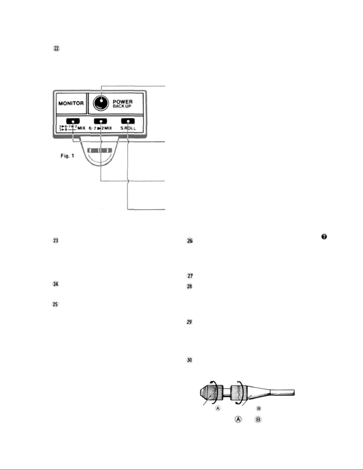
Monitor Lamps
IMPORTANT: In all instructions on control functions. Items designated by a number inside a circle
(For example 10 ) are transmitter controls normally accessable and operated in flight.
Items designated by a number within a box (Fo r example 10 ) are adjustment functions not operated
while in flight.
•Lamp A Power Monitor
• When the power switch 23 is set to ON, this lamp flashes on
briefly and then goes out momentarily as the Fail Safe data is automatically matically transmitted to the receiver. Fail Safe data is
transmitted every 60 seconds at which time the lamp al so goes ou t
momentarily. If the transmitter Nicd battery nears full discharge,
this lamp starts blinking, indicating that the power error backup
function is activated. When this occurs, transmitter memory function settings are los t and must be reset.
Lamp B3 -> 6, 7 -> 2 / 3 -> 8 Mix
This lamp comes on when Safety Switch 7 and/or 33 is set to
ACT position, indicating that throttle — flap, spoiler -> elevator
mixing and/or throttle — pitch control mixing functions are activated. This lamp will blink when transmitter control switch II is set
to ON (placing these functions in operation).
Lamp C 6, 7 -> 2 Mix 32
• This lamp comes on when Safety Switch 32] is set to ON (flap,
When the power switch 23
is set to ON, lamp A will
go out momentarily.
This indicates automatic
data transmission on and is
not a failure.
spoiler — elevator mix) or CH7 OFF (flap -> elevator mix) position.
This lamp blinks when transmitter control switch 10 is set to ON.
Lamp D Snap Roll
•When Safety Switch 29 is set to ACT (snap roll function activated), this lamp blinks. When the Snap Roll switch 13 is pulled,
this lamp continues blinking.
Power switch
• The transmitter power ON-OFF switch is provided with a locking feature to prevent accidental movement. To operate the switch, pull the
knob gently outwards and set to the desired
position (UP-ON, DOWN=OFF).
Hook
Metal hook for the accessory neck strap.
Level meter
•This meter indicates the transmitter battery
voltage and output power.
•When the antenna 26 is extended fully and
the power switch 23 is set to ON, the pointer
should move to the white zone.
• If the transmitter RF Module 32 is not installed, the meter pointer will not move.
• If the meter pointer moves to the red zone,
indicating that the Nicd battery voltage is low,
the signal range will become shorter. If the
Tachometer/timer 21 power switch is ON, the
battery alarm function will operate after about
one more flight. When the meter pointer stops
at the boundary between the white and red
zones, recharge the battery.
Antenna
Strong 1m 10cm telescoping antenna. Extend
the antenna to its full height when using the
transmitter. The antenna will lock in place with
a click when pulled up to its full height.
Carrying handle
Tachometer sensor connector
• When not using this connector and the charging socket 29, cover them with the rubberbacked cover supplied to protect them against
dust.
Charging socket and DSC (Direct Servo Con-
troller) connector
•This
connector
is
used
as
both
the
charging
socket and DSC connector. See page 10 for
charging instructions.
Non-slip adjustable lever head
The length of the lever head can be adjusted to fit
the operator.
Lever head
Lever head
Fig.
2
Unlock lever heads
, by turning them and
in the arrow direction, and adjust the head to the
most comfortable length.
Page 10
Slantable stick adjusting screws
The angle of the stick levers can be changed.
Fig.
3
Turn this screw with a Phillips
screw-driver.
The open gimbal st ick
angle can be adjusted from
about 3° to the inside to
4.5° to the outside by
turning the adjusting screw
as shown in the figure.
Adjust the stick to the
Phillips screwdriver
most comfortable angle.
The strength of the stick lever spring can be adjusted.
Remove these
screws, and
remove the
back cover.
MODE I
Fig.
Aileron
5-A
Turnwith a Phillips screwdriver.
Rudder
Elevator
The spring strength can be adjusted as desired by
removing the transmitter back cover and turning
the adjusting screw of each stick. Adjust the spring
strength for the best stick feel.
MODEII
Remove the three screws shown and remove the
transmitter righthand side panel as shown in
Fig. 5-B.
Displace th eside panel away from the case.
(slide down-off)
Disconnect the power connector.
Adjust the spring tension.
Cautions
• Be sur e that the PC board attached to the side
panel does not touch the transmitter case.
• Disconnect the power connector before side
panel completely off, while side down-ward,
to avoid touching wit h T X case.
•When the power connector is disconnected,
the memorized contents (ATV, FS, etc.) are
cleared. When flying again, reset the contents.
Elevator
Aileron
Rudder
Transmitter RF module
• Change this module when
switching frequency bands
(50, 53, 72, and 75MHz).
A temperature rise at the
RF module section during
use is normal.
Fig.
6
Fig.
Fig. 5-B
The side panel can
be removed by
4
removing these
three screws.
Transmitter
crystal
While pushing this tab to the
inside, pull t h e RF module forward.
Power connector
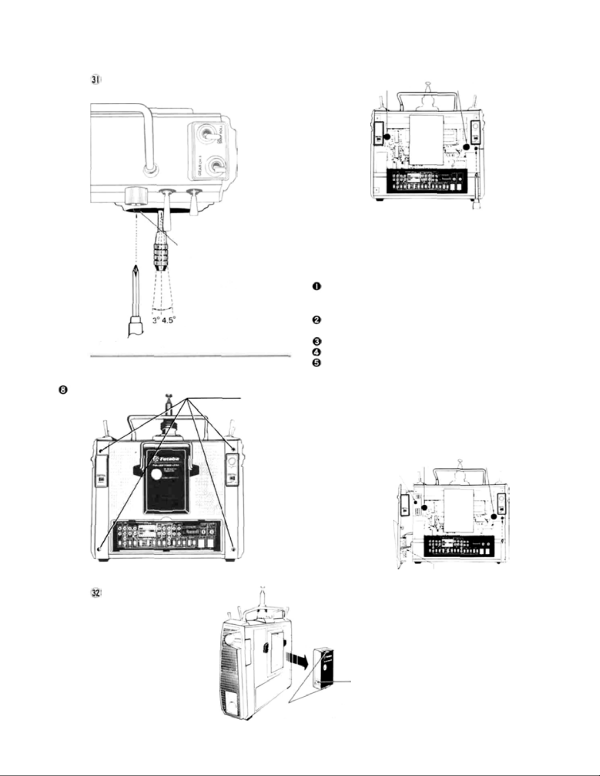
Page 11
Mini stand
• Use this stand as shown
in Figure when laying
the transmitter down.
This makes operation
easier and protects the
RF module and
transmitter back.
The 4 rubber feet
supplied can also be
installed using the
transmitter back screws.
* NOTE: The 4 rubber feet supplied as accessories
can be installed on the transmitter back
(using the longer back cover retaining
screws) to provide additional protection.
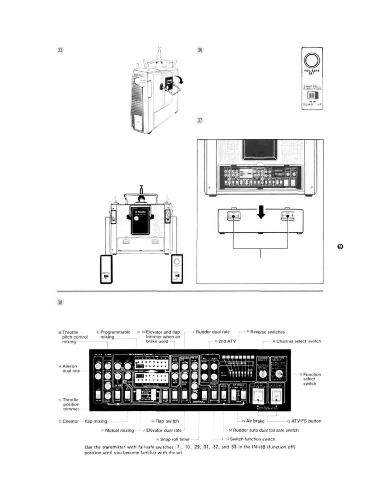
Snap roll direction switch (R/L)
Snap roll direction switch (UP/DOWN)
• These switches control
the direction of
the snap roll
when the
Snap roll
switch 13 is
used.
Fig.
Fail safe set button
• This pushbutton is used when
setting the Fail Safe servo
positions (FS instructions
Page 25).
Fig.
9
Back Cover
7
• Removal of this cover exposes the trimmer
panel. Remove as shown in Fig. 10.
Remove the back cover by pulling
these stoppers in the arrow direc-
Left-right
Fig.
8
Trimmer Panel
•This
panel
transmitter functions. Use the small screwdriver supplied with the set for making adjustments.
switching
contains switches,
Up-down
switching
buttons,
and trimmers
tion.
for
setting and adjusting the many
versatile
Fig.
10
Fig. 11
Page 12
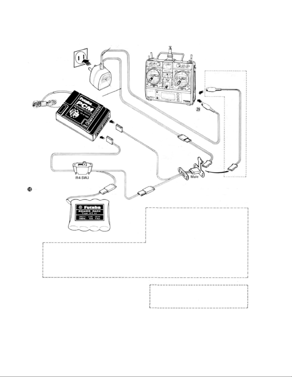
•BATTERIES AND CHARGING INSTRUCTIONS
TX (transmitter)
AC-120V
Battery charger
FBC-8B (2)
LED
Antenna
RX (receiver)
Receiver
Female
Female
Male
NR-4J
•The
Direct
Servo
Controller
system connects
the signals from the transmitter directly to
terminal C of the receiver through a wire and
controls the servos without radiating radiowaves. It is extremely convenient when flying
on the same band or during meets, etc.
Female
Install the accessory
DSC.CHG
Female
Fig. 12
Charging
socket
and
DCS
connector
Male
DSC.CHG cord
(connector with tab)
to the side of the
aircraft fuselage to
Female
CHG
Adaptor
use the charging/DSC
socket.
cord
Male
Notes:
(1) First, connect to TX Nicd and red lamp goes o n .
(2) Then, connect to R X Nicd after connecting, L.E.D.
changes color from red to greenish red (orange)
which indicates that both T X and R X Nicds are
being charged.
(3) In case o f separate charging, L.E.D, color will be:
RX Nicd-Green TX Nicd - Red
Female
•Make the connections shown in Fig.12. Connecting the special DSC.CHG cord w ith ta b to
receiver terminal C and installing it to the side
of the aircraft fuselage is very convenient.
•When the DIN connector of the DSC cord is
connected to the DSC connector 29, the
power to the encoder inside the transmitter is
turned on. The transmitter power switch is
OFF.
• When
not using the DSC, disconnect the DIN
connector.
• To operate the servos, turn on the receiver
andservo switch.
Make this
connection when
using the DSC.
DSC cord
Female
Before using your system, recharge the Nicd batteries as follows:
•Connect the DIN connector of the FBC8B (2) battery charger
to the transmitter charging socket 29 . Also connect the 3P
connector to the airborne NR-4J Nicd battery and plug the
battery charger into a 120VAC outlet as shown in Fig. 12 . The
airborne batteries can also be charged through the DSC/CHG
harness by connecting the CHG adaptor to the charger as shown
in Fig.12. In this manner, t he airborne batteries can be charged
without removing them from the model.
• Normally recharge the battery for about 15 hours. If it has not
been used for some time, discharge and recharge it two or three
times and then charge it a full 15 hours.
• The amount of time remaining be fore the batteries must be
recharged can be estimated using the Integrating Timer
function of the Tachometer/Timer 21 . It is recommended
that this function be used to monitor remaining flying time.
(See Page 11 for detailed instructions.)
• The transmitter and receiver
together or independently.
•A fully-charged transmitter battery can be used for about 10
flights of 10 minutes each. The airborne NR-4J Nicd battery
can be used for about 6 flights when
about 4 flights when 10 servos are used.
• If the system is not to be used for some time, it should be fully
charged before storage and recharged monthly to avoid full
discharge and loss of memory settings (ATV, FS, BFS memory,
etc.).
Nicd batteries can be charged
6 servos are used and
Page 13

•TACHOMETER/TIMER OPERATION
LIQUID CRYSTAL DISPLAY
Switches the range when used as a
tachometer. LOW - 100 to 30,000 rpm.
HIGH -100to60,000 rpm
Tachometer/timer power switch.
is displayed at the mode selected at
the MODE SEL key switch
INTEGRATING TIMER
Blinks during counting
and stops blinking when
counting stops.
Do not press the keys too quickly.
Press them at a speed of about once
per second. |
Selects the tachometer/timer mode.
The INTE GRATING TIMER mode is selected and
is displayed when the power is turned on,
The first time this switch is pressed, the UP TIMER
mode is selected and
The second time it is pressed, the DOWN TIMER
mode is selected and
The
third
time
it
is
pressed,
mode is selected and is displayed.
is displayed.
is displayed.
the
TACHOMETER
Fig. 13
UP TIMER
DOWN TIMER
TACHOMETER
The fourth time t h i s switch is pressed, the
tachometer/timer returns to the INTEGRATING
TIMER mode and
This switch sets the alarm time in the UP TIMER
and DOWN TIMER modes. One minute is set each
time th is key is pressed. If it is pressed and held for
two seconds or longer, the time is set in 5 minute
steps.
A beeping signal begins 10 seconds before the dot
time. A beep is produced every minute to ind ica te
the lapse of time.
This switch is used for memorization, starting,
stopping, and clearing in the UP TIMER and
DOWN TIMER modes. In the INTEGRATING
TIMER mode, thi s switch acts as the reset switch.
Do not expose the display to direct sunlight
for a long time.
is displayed.
Page 14

OPERATING INSTRUCTIONS
Tachometer
Set the tachometer/times POWER switch to ON.
appears on the display. Next, press the
MODE SEL key switch at the upper-right corner
three times. The display changes to and
the tachometer mode is selected. Hold the sensor
about 20 to 30 cm from the rotating propeller
(two blade). The propeller speed is displayed on
the
LCD.
indicates that the propeller is rotating at
12,300
rpm, set the REVOLUTION RANGE switch at the
upper left-hand corner to LOW and for propeller
speeds above 30,000 rpm, set the REVOLUTION
RANGE switch to HIGH.
The speed of a three blade
valueThe speed of a four blade propeller is 1/2 the displayed value.
rpm. For propeller speeds up to 30,000
propeller is displayed
3x2.
Make all speed measurements outdoors under
natural lighting. Accurate speed measurements
cannot be made indoors under artificial lighting
because of the affect of the 50 or 60 Hz power.
Measure the speed of the
rotating propeller at this
point.
Sensor
connector
Sensor
Connect the accessory tachometer
sensor to the sensor connector
as shown above.
To measure the speed of the main rotor of a
model helicopter, measure the speed of the tail
rotor as shown in Fig.16. and calculate the exact
speed from the equation.
Main rotor speed = ——————--—--—————————
Tail rotor speed
Main rotor and tail rotor gear ratio
Fig. 14
Make all
measurements
under natural
lighting.
Holding the sensor too close
to a spinning propeller is
dangerous.
The speed of model boat
and car engines can also be
measured in this fashion.
Warning: Use extreme caution. There is danger
serious injury or death.
of
Sensor
Sensor
Draw two lines
on the flywheel
with magic in k.
Fig.
15
Helicopter tail rotor
Fig. 16
Page 15

Note do not expose the liquid crystal display to
direct sunlight for a long time.
Switches the range when
used as a tachometer.
Tachometer/timer power switch.
is displayed at the
mode selected at the
MODE SEL KEYSW.
2 UP TIMER
Set the tachometer/timer POWER switch to ON.
key switch at the upper right-hand corner one time.
The display changes to , and the UP
TIMER mode is selected. When the ENTER key
switch at the bottom right-hand corn er is pressed, a
beep is head and the timer starts and the second
digit of the display changes every second. A beep is
is displayed. Next, press the MODE.SEL
ALARM SETTING
The alarm can be set with the TIME SET k e y. Clear
the display, by pressing the ENTER key, then press
theTIME SET key twice.
appears on the display indicating that
two minutes was set. N ext , press the ENTER key
once to memorize this two minutes. The display
changes to and is memorized. Start the
timer by pressing the ENTER key. The display
changes every second. When the display reaches
, the timer keeps ten times, every once
a second,
elapsed. Thereafter the timer continues to count
up to 60 minutes. If the TIME SET key is pressed
and held for two seconds or longer when memorizing the alarm time, the time is set in five minute
steps
to indicate that two minutes have
and the
set
alarm times
are
memorized
until
Selects the tachometer/
timer mode.
This switch sets the
alarm time.
Memorize, start, stop,
and clear switch.
Fig.
17
produced every minute to indicate the passage of
time.
To
stop
counting,
switch again. The usage time is displayed on the display. For example, means that 12 minutes
05 seconds had elapsed. The UP TIMER mode can
be used as a second stop watch. To clear the dis-
play , press the ENTER key switch again.
the power is turned off or reset. If the timer is
started without setting the time after the display
has been cleared, the previously set alarm time
remains effective. An arbitrary alarm
59 minutes can be set.
press
the ENTER key
time up to
3 DOWN TIMER
Set the tachometer/timer POWER switch to ON
and press the MODE SEL key twic e.
the DOWN TIMER mode was selected. Next,
press the ENTER key. The timer keeps.
appears on the display, and the display begins to
count down every second. The timer keeps every
second from 10 seconds before the end of the
count-down, the same as the UP TIMER.
appears on the display to indicate that
TIME AND ALARM SETTING
Set
the time and alar m wit h the TIME SET key,
the same as the UP TIMER. To set the alarm to
at the display, clear the display by
pressing the ENTER key, then press the TIME
SET key three times. Next, memorize this time
by pressing the ENTER key again. The display
begins to count down in seconds. When the display begins to count down in seconds. When the
display reaches , the timer begins to
keep every second to indicate that three minutes
have elapsed. If the TIME SET key is pressed
and held for two or more seconds, the time is set
in five minute steps, the same as the UP COUNTER, and the alarm can be set to any desired
time up to 33 minutes.
4 INTEGRATING TIMER
Set the tachometer/timer POWER switch and the
transmitter power switch to ON. The blinks,
counting begins, and the elapsed time is displayed
in minutes. For example, indicates that
three minutes have elapsed. If the transmitter
power switch is set to OF F , counting stops. When
the transmitter power switch is turned back on,
counting continues. The integrating timer function can be started and stopped as long as the
tachometer/timer POWER switch is on even if
another mode is selected with the MODE.SEL
key. This can be used to monitor the transmitter
operating time. If the ENTER key is pressed in
the INTEGRATING TIMER mode, the old integrating time is cleared and a new count begins.
Thi s can be used to forecast the remaining
Nicd battery capacity and other applications.
Page 16

•RECEIVER AND SERVOS
Receiver, Servo Switch, and
Battery Connections
8SGAP 4 Servos
Aileron servo
Elevator servo
Throttleservo
Rudder servo
Landing gear servo
Landing gear servo
Flap servo
Spoiler
servo
Fig. 18
P C M RECEIVER FP-R118GP
Antenna
wire
Crystal
20
Fig.
Power switch
SWH-5 (R4-SWJ)
Charging plug
NR-4J
Pay careful attention to the polarity
of the connector.
•This LED comes on when
receiver operated erroneously.
• When t h e receiver and servo side
Nicd is connected and this LED
is on, radiowaves are not being
received from the transmitter,
check to be sure the frequency
is correct. Checking is possible
by the l amp being on.
•When strong noise has been
received, or the radiowaves from
the transmitter are intermittently interrupted, this lampwill blink.
This is usually
not a problem.
the
Remove the receiver
crystal by pulling it in
this direction.
Receiver crystal
Pitch
control
servo
Fig.
19
Fig. 21
Page 17

•FP-S130 AND FP-S130G EXPLODED VIEWS
No.
Upper case
1.
Middle case
2.
Bottom case
3.
Ball bearing
4.
Potentiometer
5.
VR drive plate
6.
Motor
7.
Motor pinion
8.
1st gear
9.
2nd gear
10.
3rd gear
11.
Final gear
12.
2nd shaft
13.
14.
Intermediate shaft
Spacer washer 0.3T
15.
Seal ring
16.
17.
0-ring
Servo horn D
18.
Horn mouting screw
19.
S130 printed wiring board
20.
Lead wire packing
21.
S1303PB-WRB-300
22.
Screw O-nng
23.
Case mounting screw
24.
S130Nameplate
25.
PartName
Part No.
FCS-30
FCS-30
FCS-30
S04130
139995
S02753
S91243
S02461
FGS-30
FGS-30
FGS-30
FGS-30
S02481
S02480
S02486
S90415
S90426
FSH-6W
FSH-41
AS
1220
S90045
FPC-8M
S90410
J50085
S60101
Fig.
22
No.
1.
Upper case
Middle case
2.
Bottom case
3.
Motor
4.
Motor pinion
5.
1st gear
6.
2nd gear
7.
3rd gear
8.
Final gear
9.
Intermediate shah
10.
Output shaft
11.
Output shaft bearing
12.
Bent washer for SX
13.
14.
Push nut
Metal slider 0.08T
15.
TR.13VR Body 165D
16.
Fiber washer 20
17.
Binding head lapping screw
18.
Ball bearing
19.
Spacer washer 0.3T
20.
Seal ring
21.
O.ring
22
Servo horn 0
23.
24.
Horn mounting screw
25.
S130G Pri n ted wiring board
26.
Lead wire packing
27.
S130G 3PBWRB-300
O.ring
28.
29.
Case mounting screw
30.
S130G Name plate
Pan Name
Part No.
FCS-30G
FCS-30G
FCS-30G
S91243
S02461
FGS-30G
FGS-30G
FGS-30G
FGS-30G
S02480
S02803
S02804
S11043
J60070
140002
140000
S90332
J55016
S04130
S02486
S90415
S90426
FSH-6W
FSH-41
AS1224
S90045
FPC-8M
S90410
J50085
S80706
Fig.
23
Page 18

•SPLINED HORNS
The following splined horns are optional.
HORN A HORN B HORN C HOR N D HO RN E HORN F
Fig.
24
This horn permits shifting of the
servo neutral position at the servo
horn. Setting and shifting the
neutral position
a) Angle divisions
Fig.
25
1) The splined horn has 25 segments. The amount of change per
segment is; 360-25=14.4°
2) The minimum adjustable angle
is determined by the number of
arms or number of the holes. For
four arms, the minimum adjustable
angle is:
•The frequency of Futaba digit al proportional
sets can be changed among bands (1)~(6) on
the 27MHz band only.
•However, a 27MHz band set cannot be changed
to 72MHz band, and vic e ver sa .
•Therefore, always attach the correct frequency
flag to the end of the transmitter antenna.
Each frequency band has its own designated
color, as stated above. The frequency flag is
intended for identification purposes.
•Also change the frequency flag when frequency
is changed.
•Futaba paired crystals are precisely matched.
Always use a Futaba crystal set (transmitter,
receiver) when changing the frequency.
•It is illegal to change crystals of transmitter on
the 72-75MHz bands in t he U.S.A.
b) Effect
Baseline A
Fig.
26
To shift the holes center line to
the right (clockwise) relative to
baseline A, shift arm 2 to the position of arm 1 and set it to the
position closest to baseline A.
(Example] For a four arm horn,
the angular shift per segment is
14.4°. The shift to the right is 90°
- (14.4 x6 ) =3.6°
To shift by the same angle in the
opposite direction, use th e opposite arm number.
Fig.
27
For a si x arm horn, turn the arm
counterclockwise and set arm 2
to the position of arm 1. The ad-
justable angle is 60° - (14.4 x 4)
=2.4°.
Arm 3 shift 4.8° to the right, arm
6 shifts 2.4° to the left,and arm 4
shifts 7.2° to the right and left.
Fig.
28
Page 19

•BASIC LINKAGES AND INSTALLATION
The FP-8SGAP has a servo reversing switch and ATV (Adjustable Travel Volume) for
each channel. Mount the servos without regard to their direction. Select and link servo
horns somewhat larger than those specified by the model manufacturer.
• Install the servos securely. Tighten the mounting
screws until the rubber grommets are slightly
compressed. Note: If the screws are too tight,
the vibration dampening effect of the grommets
will be lost.
• Use extension cords as needed.
• It is suggested that a separate servo be used on
each aileron as this will allow use of the versatile
mixing and differential functions built into the
transmitter. Retractable landing gear can be
operated
with
age as desired.
• Connect the pushrod to each servo horn, then
check to see if the d irection of travel in relation
to stick movement is correct. If the direction of
travel is reversed, use th e servo reversing switches
to correct.
• When installing the switch harness, cut a retangular hole slightly larger that the full stroke of the
ON/OFF switch and install the switch so that it
operates smoothly. It is best to i nstall the switch
inside the fuselage and attach a piece of wire to
the switch so that it can be operated from outside the aircraft. Locate the switch where it will
not be exposed to engine oil, dust, etc.
•Wrap the receiver in soft foam rubber. Waterand dustproof the receiver by placing it in a
with a single
two
servos
servo
to
save
weight
to
simplify the mechanical link-
or
plastic bag and tyi ng the mouth of the bag with
a rubber band. Do the same with the airborne
battery pack. Caution: The foam rubber should
be loosely wrapped and not compressed. This
will provide maximum protection from vibra-
tion.
• Use the rubber bands wrapped around the receiver to hold the servo andswitch leads.
• Even though the receiver antenna may appear to
be too long, do not shorten it or fold it back.
• Be al er t fo r possible electrical noise.
This system has noise rejection circuits, however
noiseless parts are recommended.
•Operate
for slop or binding in the linkage. Unreasonable
force applied to the servo horns can damage the
servo or horns and will greatly shorten battery
life. Adjust linkages and servo horns so that the
servos move smoothly even when the tri m lever
and stick are operated simultaneously in the
same direction.
• After installation is complete, recheck each part,
then perform a range check by collapsing the
transmitter antenna and extending the receiver
antenna to its full length. Operate the transmitter at a distance of 60 to 90 feet from the receiver. The servos should operate normally at this
distance.
each
servo
to
its full
throw
and check
Normal 8 channel use (mixing and other functions not used).
Set the switches on the trimmer panel at the back
of the transmitter as shown below. The switches
are set as shown in Fig. 29. Connect the aileron
servo to CH1, elevator servo to CH2, throttle servo
Set the DIFF
trimmer 1 5
to the INHB
(counterclock
wise).
DIFF trimmer 15 set to INHB Counterclockwise.
Note: Monitor Lamps (B), (C), and (D) do not
come on at this time. Check if the direction of
operation of each servo is correct under this state.
If the di rection of operation of a servo is incorrect,
reverse the position of the corresponding servo
reversing switch [38] to [45]. Next, set the 2ND
to CH3, rudder servo to CH4, landing gear servo to
CH5, flap servo to CH6, spoiler servo to CH7, and
the pitch control servo to CH8.
ATV trimmers on aileron and elevator to the
desired deflection angles on the aircraft. The
deflection angle decreases when the 2ND ATV
trimmer is turned counterclockwise. Throttle control can be adjusted with the ATL trim lever 19
This completes the settings for basic 8 channel
use.
Fig.
29
Page 20

•USING
GENERAL - ATV (Adjustable Travel Volume)
allows independent adjustment of servo maximum
throw in each direction (without affecting the
neutral position). This is also sometimes referred
to as "separate endpoint adjustment". ATV is very
convenient when for example: a model requires
more DOWN elevator deflection than UP for equal
inside and outside loops (with equal control stick
ATV (ADJUSTABLE TRAVEL VOLUME)
deflection). Other aircraft may require slightly
different RIGHT or LEFT aileron or rudder
deflection to give equal response in each direction
(due to engine torque, precision of the model,
etc.). Two different ATV functions are possible
with this system. Memory (Pushbutton) ATV and
2ND
ATV.
MEMORY (PUSHBUTTON) ATV
This type of ATV is available on all eight channels.
Servo travel is adjusted as outlined in the example
below.
NOTE: Memory ATV settings are retained in the
transmitter memory circuit even when the power
switch is turned OFF. They are lost however, if
the transmitter Nicd battery nears full discharge or
is removed for servicing.
ATV SETTING
Switch switches(S), [49] and (R) [48]
Fig.
30
MEMORY (PUSHBUTTON) ATV - (Aileron CH1
used as example)
First,
set Function Select Switch [49] to ATV
position.
Set Channel Select Switch [48] to 1 (Ail.).
Set the transmitter and receiver power switches
ON and check for proper servo operation.
Move the Aileron stick to full RIGHT aileron,
hold it in that position, and set servo movement
to the desired Right ai lero n deflection angle by
pressing Button [46] or 47.
Repeat Step 4 for LEFT aileron.
select
For other channels,
switch 48 and adjust ATV as desired.
When all adjustments are completed, set the
Function Select and Channel Select switches
([48]and [49]) to OFF.
To clear the ATV settings on all channels, set
the Function Select switch [49] to RESET and
Channel Select switch 48 to POSITION 2 (Pos.
2 = ATV when 49 is on RESET) and press
Buttons 46 and 47 simultaneously. ATV is
cleared
on
ALL
CHANNELS and
move to 100% of their maximum throw.
If only one channel is to be cleared or changed,
simply repeat Steps I through 5 with Channel Select Switch [48] set to the appropriate
channel.
the channel
servos
with
will
ATV/FS BUTTON
•These two pushbutton switches are used for servo deflection angle setting of ATV, FS or HOLD function,
servo
test
start & stop;
reset; battery
31
Fig.
FS
memory set, etc.
This pushbutton switch is used when:
Making the ATV servo deflection angle larger.
Turning the FS function on.
Starting the servo test.
This pushbutton switch is used when:
Making the ATV servo defle c ti on angle smaller.
Turning the HOLD function on.
Stopping the servo test.
When button 46 and 47 are pressed at the same
time, reset or battery FS memory setting is pos-
sible. At this time, lamp A of memory lamps 22
goes out momentarily so that setting can be monitored.
Page 21

CHANNEL SELECT SWITCH
• This switch 48 selects the channel when setting
FS and HOLD functions. It also acts as the channel select switch for SERVO TEST function.
When switch 49 is set to RESET, the Channel
Select switch is used to designate the function
(ATV, FS, BFS memory, or ALL) to be cleared
by Buttons 46 and 47 . Note that the positions
on switch 48 have a different meaning when
the Function Select Switch is set on RESET.
This is summarized in the table below:
Channel select switch
Fig.
32
FUNCTION SELECT SWITCH
•This
switch
selects
the
function
to
be
set
(ATV,
FS, BFS memory) or test (A or B) to be performed. It is also used in the RESET position to
clear ATV, FS, and BFS memory (in conjunction
with 46, 47, and 48). Note: In RESET position, the Channel Select Switch 48 is used to
designate the function(s) to be cleared.
Function select switch
Fig.
33
• Normally set it to OFF.
FS
ALL
Switch to this position when setting fail safe
for all channels, FS is described in the "HOW
TO USE FS" section.
[48 Relationship among channel select switch
number, servo and reset.
At switch [49] FS SELECT,
No.
ATV, TESTA.B
1.
Aileron
Elevator
2.
Throttle
3.
4.
Rudder
Channel 5 switch (landing
5.
gear)
6.
Flaps
7.
Channel 7 knob (spoiler)
Channel 8 lever (variable
8.
pitch)
RESET &
TEST AL L
OFF
All the servos are
operated at servo
test.
Usually set to this OFF position.
At switch [49]
RESET
FS (fai l safe)
ATV
BFS memory
FS,
ATV,
and
memory are reset
simultaneously.
BFS
FS SELECT
This position allows setting of fail safe and
hold as described in the "HOW TO USE
FS" section.
ATV
This position allows setting ATV as described in the "HOW TO USE ATV" section.
TEST A
This position allows
in the
"SERVO TEST" section.
servo test A as described
TEST B
This position allows servo test B as described
in the "SERVO TEST" section.
BFS MEMO SET
Switch to this position when setting the BFS
release
point
as
described
in the "BATTERY
FS MEMORY SETTING" section.
OFF
Normally set to this position.
PCM GREEN CHARACTER
NAMEPLATE AND RED
CHARACTER NAMEPLATE RC
SET COMPATIBILITY
Whe n a red character nameplate transmitter and
a green character nameplate receiver are used as
a pair, only the 2 FS SELECT function of the
FUNCTION SELECT switch described above is
operative. In this case, switch is set to I FS
ALL and the receiver mode selector switch Is
set to FS. The fail safe function is ON for all
channels.
(When using the hold mode, set the receiver
mode selector switch to HOLD.)
When a green character nameplate transmitter
and red character nameplate receiver are used
as a pair, all t he function of the transmitter are
operative.
Page 22

•2ND
ATV
(CONVENTIONAL)
2ND ATV is available on the aileron and elevator
channels. This is the conventional type ATV and is
set using trimmers [34], [35]. [36], and [37] on the
transmitter back panel.
Servo movement can be adjusted from 0 to 100%.
These adjustments are retained even if the transmitter
battery
ory ATV settings are not.).
reaches a full
Aileron right-
Aileronleft-
discharge state (Mem-
When the ATV trimmer is turned clockwise, the
steering angle increases. When the ATV trimmer is
turned counterclockwise, the steering angle decreases. The steering angle can be adj us te d from 0
to
100%.
Fig.
•SERVO REVERSING SWITCHES
Elevator up
Elevator down
34
These switches reverse the direction of rotation of
the servos. They are convenient when connecting
the linkage.
NORM: Forward
REV: Reverse
Throttle
Aileron
Elevator
Fig.
CH5 switch channel
Flaps
Spoiler
Pitch control
Rudder
35
Page 23

•USING
DUAL
RATE
(AILERON, ELEVATOR, AND RUDDER)
Dual rate functions allow the flyer to alter the
maximum servo travel (and therefore control sensitivity) during flight by using the appropriate rate
switch. At D/R OFF, servo deflection is maximum
in both directions (unless limited by ATV set-
AILERON DUAL RATE
• The aileron rate switch 14 has two D/R ON positions. Thus three different servo travel rates are available
on aileron. Rates can be adjusted to suit varying aircraft and maneuver requirements.
Aileron dual rate trimmer (1)
This trimmer sets the aileron travel when the aileron dual rate switch 14 is set
to the dual ON I position.
Aileron dual rate trimmer 2
This trimmer sets the aileron travel
when the aileron dual rate switch
14 is set to the dual ON 2 position.
Trimmers [1] and [2] can adjust the
aileron travel from 40% to 80% of
the total travel.
When the dual rate switch is set to
ON, the servo throw can be set to
an arbitary angle smaller than
when the dual rate switch is OFF
(normal) as shown in Fig. 37 . Use
the throw matched to the aircraft
and the maneuvers to be performed.
tings). At D/R ON, servo deflection is reduced by
a percentage set with the D/R trimmers. Dual rate
adjustments always effect both directions of servo
travel.
LINEAR ->VTR selector
Fig. 36
ELEVATOR DUAL RATE RUDDER DUAL RATE
38
Fig.
This switch linearly switches the
aileron servo when the aileron dual
rate switch 14 is in the OFF position.
Elevator dual rate trimmer
This trimmer sets the elevator
deflection angle when the el evator dual rate switch 15 is
in the ON position. It has the
same functions as A, aileron
dual rate I .
LINEAR-> VTR selector
This switch changes the elevator servo operation linearity
when the selector dual rate
switch 16 is in the OFF position. It has the same functions as (A) aileron dual rate(1),
Fig.
37
Rudder dual rate trimmer
This trimmer sets the rudder
deflection angle when the
rudder dual r at e switch 16 is
in the ON position. It has the
same functions as A aileron
dual rate I .
LINEAR-> VTR selector
This switch changes the rudder servo operating linearity
when the rudder dual rate
switch 16 is in the OFF position. It has the same functions as (A ) aileron dual rate(1).
Page 24

•RUDDER AUTO DUAL RATE
•This
function
position. This allows a smaller rudder throw for precise inputs during rolling maneuvers (at HIGH throttle) and increased throw (at LOW throttle) during stall turns, taxing, etc.
automatically
switches
rudder
D/R to ON
as
the
throttle
lever
is
moved
from
LOW
to
HIGH
40
41
1
is set to ACT.
ON using Trimmer
Trimmer 8
can
be
used
to
•Transmitter control switch 16
can be used as a Rudder D/R switch
or for turning the programmable
mixing function ON and OFF.
Usage is determined by the Function Select switch [30] on the transmitter back panel.
• When switch 30 is set to the P
MIX position the programmed
mixing function can be turned ON
•When the Rudder Auto D/R
Safety Switch 31 is set to ACT,
rudder auto D/R is ON. If Function
Select Switch [30] is also set to
RUDD D/R, the rudder D/R can
be
turned ON and OFF with con-
trol switch 16 but the rudder auto
D/R function will still remain acti-
vated regardless of Switch 16.
set
Safety Switch [31]
Adjust desired Rudder travel in D/R
Throttle
ON and OFF . Medium slow is recommended.
SWITCH 16 FUNCTION SELECTOR
RUDDER AUTO DUAL RATE SAFETY SWITCH
Position
Fig.
Fig.
the
[21].
throttle
stick
position
or OFF with switch 16 . The Rudder D/R function will not operate
unless
is used.
• When switch
RUDD D/R position, the rudder
D/R can be turned ON or OFF with
Switch 16 . In this mode, th e programmed mixing function will remain on regardless of Switch 16 .
•When switch
the rudder auto D/R function is
inoperative. If Function Select
switch [30] is in the RUDD D/R
position, the rudder D/R function
can be turned ON or OFF with control switch 16 . Trimmer 21 sets
the rudder D/R and Auto D/R
deflection angles.
at
which
Rudder
D/R
Auto
D/R
[30]
[31]
is set to INHIB,
is
is set to the
turned
function
•USING
•VTR
(Variable
non-linear control response. It is similar to Exponential Control, but is easier to use. Aileron
will b e used as an example.
•When the Aileron LINEAR/VTR Switch [3] is
in the LINEAR position, servo travel is linear
and directly proportional to the deflection of
the transmitter control stic k as shown in Fig. 42.
In the VTR position (Ail. D/R Switch 14 must
also be in D/R OFF pos.), servo maximum throw
is unchanged. However servo tracking is the same
as when the rate switch is in the D/R I ON
position up to about 80% of the transmitter
stick deflection. Servo throw then abruptly increases to the same deflection as when D/R
Switch 14 is in D/R OFF position. Fig. 42
shows the servo movement curve when VTR is
used. Another way to think of VTR is as "automatic dual rate" that is switched off automatically as the control stick is moved past the 80%
deflection point.
VTR
Trace
Ratio)
(VARIABLE
is a new type
of
TRACE RATIO)
•
Note: Maximum
LINEAR and VTR modes and is determined by
ATV settings or maximum travel of the servo
itself if no ATV is set.
• If rate switches are set to D/R ON while in the
VTR mode, servo tracking will revert to LINEAR
and travel is set by the D/R trimmer.
servo
travel
is
the
same
in
both
Fig.
42
•When the dual
rate switch is
ON, operation
is the same as
when the
LINEAR-VTR
switch is set to
the LINEAR
position.
Page 25

•SUGGESTIONS ON ATV, D/R, AND VTR
POINTS TO REMEMBER (ATV, D/R, VTR)
•Servo maximum deflection is always determined
by ATV. If no ATV is set, maximum travel is
governed by the servo itself and is approximately
45 degrees in each direction from neutral.
•When Dual Rate is ON, servo travel in each
direction is reduced by the same percentage
(adjustable using D/R trimmers). For example,
in Fig. 43 one direction has been limited using
ATV. Both sides are reduced 20% when D/R is
ON. In other words, the ratio of UP to Down
will be maintained when D/R is ON or OFF.
• VTR operates only when D/R is set to OFF position (LINEAR/VTR switch must al so be set to
VTR position).
•Servo tracking is always LINEAR when Dual
Rate is ON (regardless of LINEAR/VTR switch).
SUGGESTIONS
• VTR is useful when different throw rates are
desired for different portions of the same ma-
neuver or when there may be insufficient time
between maneuvers for changing rate switches
manually such as in the FAI F3A or "Turn-
around" Pattern event.
•When preparing to test fly a new model, if you
are unsure as to the amount of Aileron deflec-
ti o n needed, set up as follows.
LINEAR/VTR switch 3. on LINEAR
Aileron D/R I at best estimate of desired
throw for normal flying or deflection specified on aircraft p lans.
Aileron D/R 2 less movement than D/R (1)
D/R OFF set to provide somewhat more
throw than specified.
Set Ail. D/R Switch 14 to 1, position for
takeoff.
If aileron response is not comfortable, it can
easily be increased or decreased while airborne.
• Try this set-up for AMA Pattern:
Aileron LINEAR/VTR Switch [3]
LINEAR.
Adjust D/R I to give 3 rolls in approxi-
mately 5 seconds.
Use ATV to adjust for a fast roll rate when
D/R Switch 14 is OFF .
Adjust D/R 2 for slow roll (1 roll in 5
seconds).
Same as above except Aileron LINEAR/
VTR Switch [3] set to VT R position.
OR
Fig.
43
set to
Page 26

•USING
HIGH
Servo move-
ment by
throttle lever
FS FUNCTION/HOLD FUNCTION
Fail Safe (FS) is a function which moves the servo
of each channel to a position preset (at the trans-
mitter) when an erroneous signal or continuous
strong noise is received for about 1 second or
longer. When the proper signal is lost or strong
interference received, the airborne system will
operate in the HOLD mode for about 1 second
before switching to the FS mode. When a normal
signal is received again for about 1 second, FS is
released a ndnormal control resumes.
The HOLD functionstops all servos selected (by
button [47] at
interference was received. When a normal signal is
resumed, HOLD is released.
ATL
the position just before noise or
(ADJUSTABLE
SLOW
Servo movement by
throttle trim
lever. (30% of
total travel)
Fig.
44
THROTTLE
The Throttle Trim Lever 19 affects the servo position only when t he throttle control stick is in the
LOW (IDLE) position. HIGH throttle position
remains unchanged. Adjustment of the throttle
linkage is therefore very convenient.
Use a servo horn that allows slightly more
throw than needed.
Set the maximum opening at
using Memory ATV (Page 18).
Use Memory ATV to set the extreme LOW
position to prevent servo binding when the
throttle
screw.
With the engine running, use ATL Throttle
Trim Lever 19 to set the optimum idle
speed.
A combination of FS and HOLD functions can be
selected on each channel at the modeler's discretion.
FS, HOLD, and SERVO TEST functions are operated using three switches on the trimmer panel.
barrel closes
Fig.
46
LIMIT)
HIGH throttle
against
A. ATV/FS Buttons[46] and [4 7 ]
B. Channel Select Switch [48|
C. Function Select Switch [49 ]
Channel select switch
the
idle
stop
Fig.
45
Fig.
Function select switch
47
Page 27

•FS (FAIL SAFE) AND HOLD FUNCTIONS
HOW TO USE FS (FAIL SAFE) (THROTTLE CHANNEL AS AN EXAMPLE.)
Set Function Select Switch 49 to FS SELECT.
Set transmitter and receiver power switches to
ON and check servo movements.
While switching the Channel Select Switch 48
from 1 to 8 in order, set the channel (s) to be
used
with
FAIL
SAFE by
and those to be used with HOLD by pressing
Button 47 . (In this example, set CH3 to FS
with Button 46.)
Move the throttle lever to maximum slow position,
and
press
the
transmitter back.
CH3 is now set to LOW throttle for the FS
function. After setting FS, turn the Channel
Select Switch 48 and Function Select Switch
49
to
OFF.
Test FS by turning the transmitter power
switch to OFF. (In this example, all servos
should move to neutral except the throttle
servo which should move to the LOW position
that was just set.)
FS/HOLD CAN BE CONFIRMED BY MONITOR LAMP.
• Function status can be confirmed by means of Monitor Lamp A .
When Function Select Switch 49 is at FS SELECT: Lamp A ON = HOLD
• When Switch 49 is set to FS ALL, Lamp A is OFF.
• When Switch 49 is set to ATV and Button 46 or 47 is pressed. Lamp A, blinks.
FS
pressing
Set
Button
Button
36
on
46
the
Fail Safe for all channels selected can be set
with one touch by moving the sticks and
switches of all the channels to the desired positi o ns and pressing the FS Set Button 36 once.
(Switch 49 previously set to FS ALL.)
FS settings are retained in the transmitter
memory circuit and transmitted automatically
every 60 seconds (Monitor Lamp A goes out
momentarily during data transmission.) There-
fore, resetting before each fl ig ht is unnecessary
even though the receiver switch has been turned
OFF.
After FS settings have been made, always set
Function Select Switch 49 to OFF to prevent
erroneous settings.
To clear all FS settings, set Switch 48 to Position
1, then
taneously.
Lamp A; OFF= FS
press
buttons
46
and
47
simul-
•BFS
•BFS
which moves o nly the throttle servo to the same
position as set for FS when there is only a small
amount of power left in the receiver Nicd batteries. ( If no FS position is set, the throttle servo
is moved to medium slow.)
•When BFS occurs, the throttle servo can be r eleased and throttle control regained for 36
seconds by lowering the throttle lever to IDLE.
• The throttle stick position at which throttle con-
trol is regained is programmable. This is known
as BFS Memory and is set as follows:
(BATTERY FAIL SAFE) AND BFS MEMORY
(Battery Fail
Safe)
is a warning
function
Set Function Select Switch 49 to BFS MEMO
SET and set Channel Select Switch 48 to Pos.
3 (Throttle).
Set the Throttle stick to the desired release
point (between Slow and Medium Slow recommended) and press Buttons 46 and 47 simultaneously. BFS Memory is now set.
Set Switches 48 and 49 to OFF.
Whenever BFS occurs in flight, lower the throt-
tle stick to regain control and immediately land
the aircraft.
Page 28

•SERVO TEST FUNCTIONS
• The operation of the servos can be checked by
setting the transmitter and receiver power
switches to ON.
•When switch 49 is switched to TEST-A, the
servos move half-side first and then, come back
to neutral and repeat the other-half from chan-
nel 1 to channel 8. (Channel select switch (R)
48 to TEST-ALL position at this time.) The
servos set by the channel select switch do not
operate. (If set to 5, the landing gear servo does
notoperate.)
•When switch 49 is switch to TEST-B, all the
servos operate linearly over their full travel.
(Channel select switch R 48 in TEST-ALL
position at this time.) Only the servos set at the
channel select switch are operated.
• The servo test is started by pressing button [46]]
and is stopped by pressing button 4 7.
Fig.
48
In this case, set switch [31] to the AUTO ACT
position. Rudder dual rate is then automatically
turned on and off with the throttle stick. Adjust
the throttle stick rudder auto dual rate ON and
OFF positions with trimmer [8].
VTR operation is the same as that for aileron dual
rate and elevator dual rate. Used it as desired.
Fig.
49
Page 29

•AIRCRAFT WITH VARIABLE PITCH PROP
ADVANTAGES OF VARIABLE PITCH PROPELLER
The variable pitch propeller offers such advantages as:
1. The desired speed and p u l l can be adjusted.
2. Speed matched to the engine is obtained.
3. Low noise.
4. Air braking effect by
zero pitch.
5. Idling is unnecessary.
Pitch control
servo
Linkage
Fig.
50
High pitch-
Low pitch
High pitch
Low pitch
Matching of the variable pitch propeller to the digital proportional RC set is essential. Improper use is extremely dangerous. Therefore, read this section carefully.
Connect the
pitch
control
servo
to
channel
8. A variable
pitch
propeller
can
be
adequately controlled by
common servo. Handle the servo the same as any other servo.
Install the servo and linkage as specified by the manufacturer. (Note) This section explains how to use a
MK variable pitch propeller.
Set switch
[7]
to the ACT
position. Turn trimmers[4]
and
[5]
fully counterclockwise.
Since trimmer 6 is adjusted
after making a test flight, set
it to about the center.
Switch II is the mixing ONOFF switch. When it is set to
the OFF position, monitor
lamp 22 B comes on. When
it is set to the ON position,
the lamp goes out. Set the
switch to the ON position
and check the pitch control
* The pitch is zero (minimum) when the throttle
lever is set to minimum slow.
* The pitch becomes 11 (maximum) when the
throttle lever is raised one stop.
Next, adjust the transmitter upper side pitch con-
trol HIGH
side
trim
lever 8 throw.
Set
the throttle lever to the HIGH side before making this
adjustment. Since lever 8 should be l inked with
pitch 11 (maximum) the propeller pitch when this
lever is set to the lowest position must be checked.
A variable pitch propeller is difficult to measure
with a pitch gauge. Therefore, adjust trimmer [ 6]
for a pitch somewhat lower than the maximum
pitch 11 .
(channel 8) servo stroke and
direction. Set the servo so
the propeller is pitched when
HIGH
the throttle stick is set to
HIGH and is zero pitch when
Fig.
51
the throttle stick is set to
LOW. If the servo turns in
the wrong direction, reverse
the setting of servo reversing
switch 57 .
Fig.
52
Next, adjust the servo stroke. First set the transmitter pitch control lever 8 to the HIGH position. Then adjust the pitch control servo stroke
with the ATV trimmers 48 and 49 so a load is not
applied to the linkage. Set th e mixing throttle position is 1 stop from the SLOW position (Fig. 52)
Pitch 11 (maximum)
at one stop
with the THROT POSIT trimmer [8], and check
if:
a
Pitch 0 (minimum) in slow
Page 30

Pitch 11
(maximum)
Pitch control
high side trimmer
Pitch 8-9
Pitch zero does not have an air braking affect. If
the engine is running at a speed of 3000 ~ 4000
rpm, the air braking effect will not appear if the
propeller diameter is too small.
Adjust the throttle so the pitch is positive and the
engine idles when switch II is set to the OFF
position. Since lever 8 is also operative in this
state, optimum pitch adjustment is possible.
Idle up lever
NOTE:
When lowering lever 8 , be careful that the pitch
does not go negative. This is adjusted during flight.
Operation when switch
is
ON
Forexample, fli ght is affected by the temperature,
air pressure, wind, and other conditions. Use this
lever adjusting the speed, pull, etc. to your liking.
Also select the engine tone quality by adjusting
the propeller pitch. Make quiet flights by fine adjusting th epropeller pitch.
Next, adjust the throttle. First, set switch II to
the OFF position. Adjust the engine idling speed
to 2,200~2,500 rpm with the throttle trim lever
19 . Then set switch II to the ON position and
set the throttle lever to the maximum slow (zero
pitch) position. Adjust idle up lever 9 for an
engine speed of 3000 ~ 4000 rpm. Lever 9 is
inoperative when switch II is in the OFF position. Use the variable pitch propeller as an air
NOTES:
• The pitch always becomes maximum when the
throttle switch is set to HIGH.
•The
speed
lever 9 when the propeller pitch is zero.
• Since t he a ir braking effect is higher t han normal
when landing at zero propeller pitch, be careful
until you become familiar wi th t he setting.
• Best result is often obtained by making the
tuned pipe longer.
brake during dives.
VARIABLE PITCH PROPELLER AND ENGINE
POW ER MATCHING IS ESSENTIAL FOR MAXIMUM PERFORMANCE
If
the throttle stick is operated quickly during
flight, the engine will make an abnormal sound
(sputter). If the engine sound remains unnatural,
the pitch control or throttle servo operation tim-
ing can be d el ayed.
When the t hr ottle lever is suddenly moved from a
high speed to a low speed, the throttle operates
before the propeller pitch changes to zero. If the
throttle lever is moved from HIGH to SLOW, the
pitchwill change before the throttle operates.
Set the throttle delay time with trimmer [4] and
the pitch delay time with trimmer [5] . This
provides the same fe e li ng as fixed propeller ai rc ra ft
andallows natural flight.
cannot
be
increased
Fig.
with
55
the idle up
Page 31

•THROTTLE POSITION TRIMMER
Throttle stick
Throttle -> pitch control
mixing
This is the start position setting
trimmer when M rudder auto dual
and N air brake are used.
• (B) Throttle -> pitch control mixing
The pitch control servo mixing point can be set
to an arbitrary point between throttle lever 3
maximum slow and medium slow. When the
throttle lever is moved from SLOW to HIGH, the
mixing function is turned on. When the throttle
lever is moved from HIGH to SLOW, the mixing
function is turned off.
The start point can be set to the point at which
maximum engine torque and propeller air braking affect is displayed. (Normally, set it to within a range of one or two stops from the slowest
position.)
• M Rudder auto dual rate
Rudder dual rate can be automatically turned on
and off from any point between the throttle
lever 3 maximum slow and medium slow posi-
tions. (When M switch is in the ON position.)
When the throttle lever is moved from SLOW to
HIGH, rudder dual rate is turned ON. When the
throttle lever is moved from HIGH to SLOW,
rudder dual rate is turned off. Rudder dual rate
trimmer 21 set the deflection angle when rudder
dual rate is on.
• (N)
Air brake
Air brake (flap, spoiler -> elevator, throttle ->
flap, spoiler -> elevator) mixing can be set to any
point between the throttle lever 3 maximum
slow and medium slow positions. When the
throttle lever is moved from SLOW to HIGH,
mixing is turned off. When t he throttle lever is
moved from HIGH to SLOW, mixing is turned
on.
•AIRCRAFT WITH FLAPS
Connect the flap servo to channel 6 of the receiver.
• Flaps are normally controlled by the CH6 Knob
6 on the transmitter front. Wide or narrow
(Flap Trim) travel may be selected by Flap
Switch 18 on the trimmer panel.
' Wide throw is often best fo r normal landing flaps
and airbrake operations.
Narrow (Trim) throw allows Flaps or Flprons
(see page 31 ) to be used fo r pitch trim adjust-
ments in knife edge and vertical maneuvers.
Narrow throw may also may also be best for
Elevator -> Flap (2 -> 6) mixing.
Page 32

•ELEVATOR/FLAP MIXING
ELEVATOR -> FLAP MIXING
• Switch 10 : ACT
• Switch 18 : TRIM
Fig. 58
FLIGHT ADJUSTMENT
• Elevator -> Flap (2 -> 6) mixing is unidirectional
with elevator (CH2) acting as the Master chan-
nel. This function can be helpful in looping,
square cornered, and circular acrobatic maneuvers. Set up the function as foll ows:
Set Safety Switch 10 to ACT and Flap Switch
18 toTRIM.
Set Control Switch 12 to ON and adjust Trim-
mer [9] to give DOWN flaps with UP elevator
stick movement.
Initially, set deflection angles so that the flap
down angle is approximately the same
elevator up angle.
Transmitter Control Switch 12 is used t o turn
this function ON and OFF in flight as desired.
as
the
Make a test flight with Switch 12 OFF and
adjust the Elevator trim and deflection to suit.
Fig.
59
•FLAP/ELEVATOR
FLAP -> ELEVATOR MIXING (ELEVATOR DOWN MIXING) ADJUSTMENT
•This
is a pre-set
ing and is ideal for landing approaches with
stunt and scale aircraft. An airbrake effect is
produced which is very realistic and makes short
field landings easier.
Fig.
61
or
switch-activated
Flaps 45 ~60
MIXING
type
of mix-
Turn Switch 12 ON and test control response.
If the response is not correct, turn switch 12
OFF, land and ad j u s t flap deflection with Trimmer
9
.
Most common maneuvers can be performed
with the mixing function ON. Rolls and spins
may be better without the mixing depending on
the aircraft. Mixing is generally not recommended for landing.
(PRE-SET FLAPS
Set Airbrake Switch 32 (6, 7 -> 2 MIX) to ON.
Monitor Lamp (C) comes ON. Control Switch
10 can be used to turn the function ON and
OFF
in flight. When Switch 10 is ON, Lamp
C Blinks.
Turn Switch 10 ON and set Flap Knob 6 to
Zero. Lower the flaps 45 to 60 degrees using
Trimmer 20 and set the Elevators about 3
degrees down using Trimmer 19 . NOTE: These
settings are estimates and will vary depending
on elevator and flap areas, etc.
Set Switch 10 to OFF for takeoff. When at a
safe altitude, reduce the throttle to medium
slow and after the aircraft has slowed somewhat, turn Switch 10 to ON. The aircraft
should maintain level flight. If the aircraft
climbs or dives, set Switch 10 to OFF, land,
and readjust the elevator angle as necessary
with Trimmer 19 . Remember, do NOT try to
adjust back panel trimmers while in Flight.
Make adjustments in small steps.
Flap Neutral position can be changed in flight
using the Flap Knob 6 . This applies whether
mixing in ON or OFF.
AND
ELEV.
TRIM)
Page 33

•AIRCRAFT WITH FLAPS AND SPOILERS(AIRBRAKE)
Connect the Flap servo to CH6 and the Spoiler
servo to CH7 on the Receiver. Set Switch [32]
to
ON.
62
Fig.
Set Control Switch 10 to ON and adjust the
flaps as shown in Fig. 62 with Trimmer 20.
Adjust the spoiler servo travel with Memory
ATV Trimmers [46] and [47]. (See Page 17)
When used in this manner, flaps and spoilers
will be deployed simultaneously to the pre-set
positions when Switch 10 is set to ON. This
acts as an airbrake. NOTE: In this mode, the
Spoiler Knob 7 will be inoperative and its
function transfered to Switch 10 . Alternative-
ly, Switch 32 can be set to CH7 OFF and Knob
7 used for spoiler control.
Elevator Trimmer 19 can be adjusted if necessary so that the aircraft maintains level flight
with the airbrake deployed.
•FLAP TRIM FUNCTION
FLAP TRIM
Knob 6 throw selector. In the
NORM position, wide throw is
selected and in the TRIM position,
narrow throw is selected.
Flap Neutral can be adjusted
during flight using the CH6
Flap Knob 6 .
•This is helpful in making
pitch axis trim adjustments for knife
edge and vertical maneuvers.
•This
function
Mixing Switches 10 and 12 are ON
or
OFF.
AUTOMATIC AIR BRAKING (THROTTLE STICK OPERATION)
•This
feature
the airbrake (flaps and elevator or flaps, spoilers,
and elevator) as the throttle stick is lowered.
can
be
permits
SLOW
used
whether
automatic
deployment
Fig.
of
66
• Flap Switch 18 on the trimmer panel can be set
to TRIM position to provide a finer adjustment
if desired. (This may not be possible however, if
wider angles are needed for other flap functions.)
When the throttle is again moved to HIGH, the
airbrakes are retracted automatically. Operation
in this manner is v ery efficient as it allows the
use of the airbrake function while leaving the
pilot
free
trols.
Set Switch [32] to INHIB and Switch [33] to
ACT. Monitor Lamp B comes on.
Set Control Switch 1 1 to ON. Lamp B blinks.
Trimmer 8 is used to set the throttle stick
position at which the airbrake is deployed.
Deployment at one or two stops from the maximum Slow position is usually th e most suitable.
The Auto Airbrake function can be turned ON
and OF F in flight by using Control Switch II .
• The Automatic Air Bra ke Function is very useful
for slowing the aircraft during maneuvers and
landing approaches. When executing a "go
around" fo r a missed approach, the airbrake will
be immediately released as the throttle is moved
to HIGH.
to
concentrate
on the
primary
con-
Page 34

•SNAP ROLL SWITCH (TIMER IS OPTIONAL)
•When this function is used, snap rolls can be
performed by pushing the Snap Switch 13 . Snap
roll directions can be set using Control Switches
34
and
35
.
Set Safety Switch 29 on the trimmer panel to
ACT. Monitor Lamp D will blink.
A snap roll in the direction set by switches 34
and 35 can now be performed by pushing Control Switch 13 to ON. The aircraft will continue to roll as long as the switch is held ON
unless the optional timer function is installed.
The optional timer function can be used to
automatically stop the snap roll. Trimmers
(25), [26), [27], and [28] can be used to set the
time in each direction. The time can be varied
from 0.2 to 2 seconds.
NOTE: The Snap Switch 13 is positioned so
that it is easy to reach. When the snap
roll function is activated, you must
use great care not to push the switch
inadvertently. When the snap roll
function is not desired, always set
Safety Switch [291 to INHIB.
SNAP ROLL TIMER (OPTION)
These ar e the s nap roll time setting
trimmers and snap roll function
safety switches.
Right up snap roll time setting trimmer for button 34 .
The snap roll time is settable
fr om 0.2 t o 2 seconds.
Right down snap roll time
setting trimmer for button
35 . The snap roll time is set-
table from 0.2 to 2 seconds.
Left up snap roll time setting
trimmer for button 36 . The
snap roll time is settable from
0.2 to 2 seconds.
Left down snap roll time setting trimmer for button 37.
The snap roll time is settable
from 0.2 to 2 seconds.
Snap roll function safety
switch.
•PROGRAMMABLE MIXING AND EXAMPLES
• Programmable mixing of any two channels
desired is possible using the mix ing board on the
trimmer panel. Programmable mixing is NOT a
memory function and all programmed mixing
is of the unidirectional type.
• The Master and Slave channels can be designated using Jumper Connectors 13 and 14 . The
mixing amount in each direction of servo movement is adjustable using Trimmers 11 and 12.
•When Programmed Mixing is not in use. Connectors 13 and 14 should be placed in the
INHIB position as shown in Fig. 68.
•When Function Select Switch 30 is set to P.
MIX, programmed mixing can be switched ON
and OFF in flight using Control Switch 16 .
When Switch 30 is set to RUDD D/R, program-
med mixing will remain ON if activated using
Connectors 13 and 14, and Control Switch 16;
Fig.
68
can be used to turn the Rudder Dual Rate function ON and OFF.
Page 35

EXAMPLE 1. Fig. 69. AILERON -> RUDDER MIXING
• This function is sometimes referred to as"CAR" (Coupled Ailerons and Rudder) and is useful on sailplanes
and certain scale models where aileron and rudder must be used together f or coordinated turns.
Connector 4 designates the Master channel
and is set vertically at the CH1 (Aileron) position.
Fig. 69
EXAMPLE 2. Fig. 70.
•Programmed Mixing can be used to correct an
unwanted UP or DOWN pitch movement of the
aircraft when Rudder is during knife edge and
rolling maneuvers.
Set the Mixing Board as shown in Fig. 70 to
provide mixing from Rudder -> Elevator.
Use Trimmers 11 and 12 to adjust the desired
amo unt and direction of Elevator compensation
when Rudder is applied in both Left and Right
directions.
Connector13designates the Slave channel
is set vertically a t the CH4 (Rudder) position.
Set Switch
the mix function ON and OFF in flight. Otherwise, it will remain ON and Control Switch 16
is available for
ON/OFF Switch.
NOTE: If Switch
OFF Switch, Rudder Dual Rate cannot be
switched manually, but Auto Dual Rate Rudder
ca nstill be used.
Use Trimmers 11 and 12 to set the amount
and direction of desired Rudder movement
when the Aileron stick is deflected.
30 to P. M IX
use as the Rudder Dual Rate
16
if it is desired to
is used as the P. MIX ON/
Fig.
and
turn
70
EXAMPLES. Fig.71.
•
Certain
dihedral or stunt aircraft with incorrect dihedral
may exhibit an unwanted rolling tendency when
Rudder is applied (as opposed to a pure Yaw
motion). This can cause variations in the roll rate
during
during point rolls and knife edge maneuvers.
This can be corrected with Programmed Mixing.
Fig.
71
EXAMPLE 4.
•A n unwanted Left or Right Yaw tendency during pull ups can be adjusted by setting the mixing panel
for Elevator to Rudder mixing (Elevator CH2 is the Master channel).
aircraft
slow
Set the mixing panel as in Fig. 71 to provide
mixing from Rudder to Aileron.
Trimmers 11 and 12 can be adjusted so that a
small amount of corrective Aileron is automatically applied with Rudder movement. Both
directions of Rudder movement can be adjusted
for.
such
rolls
and/or a "roll
as
scale
models
out"
with
large
tendency
Page 36

•MUTUAL(BI-DIRECTIONAL)
MIXING (FLPRON, ELEVN, V-TAIL, DIFF)
Aileron + flap (FLPRON), aileron + elevator (ELEVN), rudder + elevator (V.TAIL), and aileron differential
(DIF) mixing can be selected with a switch.
FLPRON (AILERON + FLAP)
•This
function
with full length "strip" ailerons.
•
Use
a separate servo on each aileron and connect
as shown in Fig. 61 . NOTE: Always connect the
servo on the Right Aileron to CH1 (Aileron).
The Left servo to CH6 (Flap).
• Set Switches 16 and 17 as shown in Fig. 72.
• Aileron differential can be varied to suit using
Trimmer 15 . Trimmer 15 will vary the amount
of DOWN travel available on each aileron. UP
movement is not affected.
allows
the
use
of
flapson aircraft
•The
Flap
function
Flap Knob 6 or better by using Switch 10 to
activate the Fla ps and Elevator trim if necessary
(See Flap -> Elevator Down mi x i n g Page 30).
• Elevator -> Flap mixing is possible by setting
trimmer panel Switch 10 to ACT and Control
Switch 12 to ON. (See Elevator -> Flap mixing
Page 30)
• Pitch trim in vertical maneuvers and point manuvers can be adjusted easily by using the Flap
Knob 6 .
• NOTE: When the ailerons are operated while in
the Flap DOWN mode, an additional downward
movement of the Aileron occurs. Wing tip stall
can occur easily if the Aileron is down too far.
To
prevent this, it may be necessary to use the
aileron differential (Trimmer 15) to reduce the
downward travel.
can be operated by
using
the
Fig. 72
Fig. 7 3
Fig. 74
* Always connect the servo at the right wing to
receiver channel 1 ( a i le r on).
Page 37

ELEVN (AILERON + ELEVATOR)
•
This type of mixing
delta wing aircraft and flying discs.
• Install and connect the servos as shown in Fig.
75. Always connect the Right side servo to CH1
(Aileron).
• Aileron differential can be adjusted with Trimmer
15.
can
be
used
with
tailless
and
Connect to channel 2
(elevator).
V.TAIL (ELEVATOR + RUDDER)
•This
mixing
Bonanzas, and other V-Tail aircraft.
• Install and connect the servos as shown in Fig.
78. Al way s connect the servo to the Right Rud-
dervator to CH2 (Elevator).
• Set Switches 16 and 17 as shown in Fig. 79.
is
used
for
gliders,
-Connect to
channel 1
(aileron).
Pig.
scale
model
75
Use channel 1 (aileron
servo) at the right rudder.
Fig.
Fig.
76
77
Connect to
channel 4 (rudder)
* When connecting the linkage, connect channel 2
(aileron servo) to theright wing rudder.
Connect to
channel 2 (elevator).
Fig.
78
Fig. 79
Used channel 2 (elevator) for the right rudder.
Fig.
80
Page 38

 Loading...