

Page 1
Futaba
DIGITAL PROPORTIONAL
RADIO CONTROL
Page 2

THANK YOU for purchasing a Futaba digital
proportional radio control set.
Please read this manual thoroughly before using your
new
set.
CONTENTS
Features........................................................................
Contents
Transmitter
Using
Using
Modules........................................................................
Warranty
Repair and
and
Ratings
Controls
the
Transmitter
the
Receiver
.....................................................................
Adjustment
...................................................
......................................................
...................................................
and
Servos
.......................................
Service
.......................................
Page 3

• FEATURES
This radio control set has been developed for FAI RC
acrobatic F3A use. Please read this manual thoroughly before
using your set.
Transmitter FP-T8JN
•The transmitter employs a module system. The
frequency band and modulation method can be
changed with one touch.
•The
servos
can
be
operated
radio signals. Wire operation is possible by using
the special cord furnished with the set.
•A reversing device is self-contained. The servo
can be reversed by switching a switch.
•An aileron and elevator angle switching device is
self-contained.
•Open gimble sticks provide maximum feel.
•An travel adjuster is self-contained.
Servo travel is independently adjustable to the left
and right (up, down).
•Elevator and flap mixing. Amount and direction
are variable. Release switch is also provided.
•Flap
and
spoiler
are variable. Release switch is also provided.
•Two
roll buttons. Elevator angle and
can be freely adjusted.
•Two
snap
rudder angle and direction can be freely adjusted.
•Throttle button. Throttle half can be freely
adjusted.
•Hook band is standard. Since this transmitter has
numerous accessories, hanging it from your neck
with this band makes operation easier.
•Buit-in
antenna. Locked when
roll
mixing.
buttons.
stage.
•Human engineered exterior. Superior operability.
without
Amount
Aileron, elevator, and
pulled
transmitting
and
direction
direction
up
one
stage.
Receiver FP-R8J
•Module type. The frequency band and modulation
method
as the transmitter.
•Eight
and rugged case.
•All
pins. Housing is also special and provides an excellent feeling. Resistance against vibration and
shock has been improved substantially.
•One-stage FET RF amplifier. Two signal characteristic is superb.
•Servos can be controlled without transmitting by
connecting the transmitter directly to a "C"
terminal.
can be changed
channels
connectors
with
packed
in a compact,
have
trouble-free, metal
one
touch,
lightweight,
the
plated
same
FP-S121, FP-S121H and FP-S121G
servos
•Compact, lightweight, rugged.
•Powerful output torque (3kg-cm).
•Output
•Waterproof, dustproof type.
•Special 16/o micromotor.
•High-speed servo (FP-S121 H) is also available.
•Standard equipment includes two 8-channel,
shaft
is
supported by
assure excellent neutral characteristics and ample
durability.
6 servo landing gear servos (FP-S121G).
two
ball bearings
to
Page 4

• SET CONTENTS AND RATINGS
Transmitter FP-T8JN
Operating system
Transmitting frequency
Modulation system
Power requirement
Current drain
: Two-stick, 8 channels
: 27MHz, 53MHz Bands
72MHz Band
:
AM or FM
Selectable by changing
modules.
: 9.6V 8/500mAH
: 150mA
Set name
Transmitter
Receiver
Servo
Landing gear servo
Switch
NiCd battery
Accessories
FP-8JN
FP-T8JNx1
FP-R8JX1
FP-S121x4
FP-S121Gx2
R4-SWJx1
NR-4Hx1
Charger, extension cord, landing gear adapter,
DSC cord, ribbon, horn, servo tray
Servo FP-S121
Control system
Operating angle
Power requirement
Current drain
Output torque
Dimensions
Weight
+ pulse width control
1520 uS.N
One-side 45° or greater
(including trim)
4.8V
8mA (when stopped)
3.0kg-cm
39.0 x 19.0 x 31.5mm
36g
Receiver FP-R8J
Receiving frequency
Intermediate frequency
Power requirement
Current drain
Dimensions
Weight
Receiving range
: 27MHz, 53MHz Bands
72MHz Band
Selectable by changing
modules.
:455kHz
:4.8V
:
16mA
: 49.0 x 42.0 x 24.0mm
:52g
: With FP-T8JN trans-
mitter
500m on the ground
1000m in the air
Servo FP-S121G
Control system
Operating angle
Power requirement
Current drain
Output torque
Dimensions
Weight
+ pulse width control
160° or greater
4.8V
8mA (when stopped)
3.5kg-cm
39.0 x 19.0 x 31.5mm
36g
Charger FBC-2 or FBC-2L
Input voltage
Output
: AC110V,50/60Hz,
4VA
: Tx side 9.6V 45mA
Rx side 4.8V 45mA
NiCd battery for receiver servo
NR-4H
Voltage
Dimensions
Weight
: 4.8V 4/500mAH
: 32.5 x 32.5 x 57.0mm
:
115g
Page 5
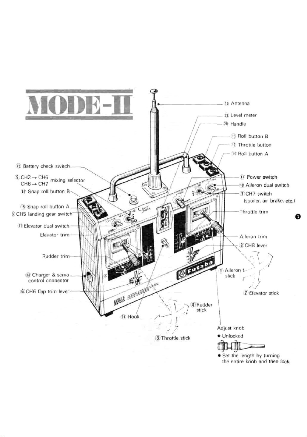
• TRANSMITTER CONTROLS
Fig.1
Page 6

Purpose of switches and trimmers in Fig. 2
The numbers in circles represent the channel
number. The channel numbers on the front of
the transmitter correspond to the receiver
connector output numbers.
Aileron reverse switch
NORM-REV This switch reverses the direction of rotation of the aileron servo.
Elevator reverse switch
NORM-REV This switch reverses the di-
rection of operation of the elevator servo.
Throttle reverse switch
NORM-REV This switch reverses the di-
rection of operation of the throttle servo.
Rudder reverse switch
NORM-REV This switch reverses the di-
rection of operation of the rudder servo.
ALT (Adjustable Limit Throttle)
This switch selects whether the operating angle
is varied at the HIGH side of the stick or the
LOW side of the stick when the maximum
operating angle of the servo is adjusted with
the throttle trim. Normally use at the LOW
side.
Aileron ATV (Adjustable Travel Volume) R
AIL, ATV-R This trimmer adjusts the
aileron travel in the right direction when
the aileron reverse switch is in the NORM
position.
Travel is continuously variable from 50%
to 100% of the total travel range.
Aileron ATVL
AIL, ATV-L This trimmer adjusts the
aileron travel in the left direction when the
aileron reverse switch is in the NORM
position. Adjustment range is the same as
that of above.
Aileron dual trimmer
AIL DUAL This trimmer adjusts the
aileron travel when the aileron dual rate is
ON. (This trimmer is adjusted at kick down.)
Travel is continuously variable from 40%
to 100% of the total travel range.
Page 7

Throttle button trimmer
THROT The throttle servo is operated at
the position set by this trimmer by pushing the throttle button.
The total travel can be set at throttle stick
neutral position.
Roll A button trimmer 1 ROLL (A)
Roll B button trimmer 1 ROLL (B)
This trimmer sets the aileron travel when the
roll button is pushed.
The travel is variable over the entire travel
range at aileron stick neutral.
Snap roll A button aileron trimmer
SNAP ROLL (A) 1 AIL
Snap roll B button aileron trimmer
SNAP ROLL (B) 1 AIL
These trimmers set the aileron travel when the
snap roll button is pushed.
The travel can be varied over the entire travel
range.
Snap roll A button elevator trimmer
SNAP ROLL(A) 2 ELEV
Snap roll B button elevator trimmer
SNAP ROLL(B-> 2 ELEV
This trimmer sets the elevator travel in the
same manner as trimmers and
Snap roll A button rudder trimmer
SNAP ROLL(A) RUD
Snap roll B button rudder trimmer
SNAP ROLL (B) RUD
These trimmers set the rudder travel in the
same manner as trimmer and
Elevator, flap MIX trimmer
MIX ELEV-> FLAP
This trimmer adjusts the amount of mixing
from the elevator to the flap.
The travel can be varied over the entire travel
range at flap channel neutral.
Spoiler (channel 7), flap (channel 6) MIX
trimmer
MIX SPOIL-> FLAP
This trimmer adjusts the amount of mixing
from the spoiler to the flap.
Travel range is the same as that of trimmer
Elevator dual trimmer
ELEV. DUAL
This trimmer adjusts the travel at elevator dual
rate ON.
The travel is continuously variable from 40%
to 100% of the total travel range.
Channel 6 flap neutral trimmer
MIX NEUTRAL
This
trimmer
nel 7) and flap (channel 6) mixing.
Neutral adjustment is possible in all spoiler
states.
sets
flap neutral at spoiler (chan-
Elevator ATV U trimmer
ELEV. ATV-U
This trimmer adjusts the elevator travel in the
UP direction when the elevator reverse switch
is in the NORM position. Adjustment range
is the same as that of the aileron ATV
Elevator ATV D trimmer
ELEV. ATV-D
This trimmer adjusts the elevator travel in the
DOWN direction when the elevator reverse
switch is in the NORM position. Adjustment
range is the same as that of the aileron ATV
Rudder ATV R trimmer
RUD. ATV-R
This trimmer adjusts the rudder travel in the
right
direction when the rudder
is in the NORM position. Adjustment range is
the same as that of aileron ATV
Rudder ATV L trimmer
RUD. ATV-L
This trimmer adjusts the rudder travel in
left direction when the rudder reverse switch
is in the NORM position. Adjustment range is
the same as that of aileron ATV
Transmitter module
The frequency, frequency band and modulation method can be changed by changing this
module. The method of changing this module
is shown in Fig. 12.
Trimmer panel
This panel is removed by sliding it in the direction of the OPEN arrow.
reverse
switch
Page 8

• USING THE TRANSMITTER
Before using the transmitter, charge the NiCd
battery.
•Connect the DIN connector of the FBC-2L
charger to the charging jack of the transmitter
and the 3P connector to the receiver servo NiCd
battery (NR-4H), and plug the charger into an
AC110V outlet as shown in Fig. 3. The Tx, Rx
charging indicator LED illuminate to indicate that
the battery is being charged.
•The charging time is normally 15 hours. But if the
battery has not be used for some time, charge it
for about 20 hours.
(If the battery is left in the discharged state for a
long time, its capacity and life will be adversely
affected.)
•The
transmitter and
be charged simultaneously, or independently.
•The battery can usually be used about 10 times
at a rate of about 10 minutes/time.
•Extend the antenna.
Pull the
counterclockwise until it locks as shown in Fig. 4.
•If the antenna is not locked, it will not be connected to the internal circuitry.
•The power switch is a lock type switch. When it
is set to ON while pulling it forward, the level
meter pointer will deflect, indicating the antenna
output. The transmitter is OK if the pointer
deflects to graduation 7 with the antenna extended fully.
The pointer indication is different when the
antenna is contracted and when it is extended
fully.
[The pointer indication will also be different
when the antenna is grasped with your hand and
when it is not grasped.)
When the antenna is contracted, the transmitter
does not deliver an output even though the level
meter pointer deflects. DO NOT USE THE
TRANSMITTER UNDER THIS STATE.
•Push the battery check switch. The level meter
pointer will indicate the battery voltage at this
time. The battery is OK if the meter pointer deflects to within the green zone. If the pointer deflects to near the boundary between the green
and red zones, recharge the battery.
•Using the D.S.C. function
The
by connecting the D.S.C. cord furnished with the
set to the connector (Fig. 1 ) of the transmitter and the C terminal of the receiver. This
allows adjustment of the aircraft while awaiting
your turn to fly.
first
servos
stage
can
receiver
of the antenna up and
be
operated
NiCd batteries
without
can
turn
transmitting
it
(Use this function with the power switch of the
transmitter set to the OFF position. Although
the D.S.C. Function will be operative when the
power switch is set to ON, it will be meaningless.)
•Using dual travel
(DR —aileron, DR —elevator)
When the dual travel switch is set to ON, the
steering angle becomes small (within the range
indicated by the hatched lines in Fig. 5). The
steering angle can be varied from 40% (minimum)
to 100% (maximum) of the total steering angle
by adjusting the trimmer
next to the switch with a screwdriver. The dual
switch should normally be set to OFF. However
on the trimmer panel for channel 8)
Page 9

when desiring to make the spin and other steering
angles large, set it to ON and adjust the horn, adjusters, and trimmers for level flight.
When the dual travel switch is set to OFF, kick
up is set, and the steering angle becomes large.
•Aileron,
DOWN) angle adjustment
[ATV (Adjustable Travel Volume)]
The aileron, elevator, and rudder steering angles
can be made small within the range of the hatched
lines in Fig. 6.
When the aileron right roll and left roll rates are
different, they can be made the same by adjusting
the and trimmers of Fig. 2.
This also applies to the elevator and rudder.
elevator UP and DOWN difference can also
provided for easier flying.
The elevator ATV trimmers are
The rudder ATV trimmers are
•Elevator and flap mixing adjustment
Connect the flap servo to channel 6 of the receiver.
When the MIX switch of Fig. 1 is set to
the elevator and flaps are mixed. Set the steering
elevator,
and rudder
of Fig. 2.
of
right
Fig. 2.
and left (UP.
An
be
point, linkage is extremely simple.
Dual travel is operative even at elevator and flap
mixing.
Use the CH6 flap trim lever of Fig. 1 to adjust
the flap neutral position. Use this trimmer is the
same manner as a trim lever (aileron trim and
elevator trim).
Mixing is released when the MIX switch is set to
the center position (• mark). The flap neutral
position is not changed at this time.
(NOTE) Channel 6 is for the flaps, but can also be
used as a spare channel. However, since the
travel range is slightly narrow, adjust the
linkage.
•Adjustment when mixing spoiler, etc. and flaps
(When using the flaps and spoiler as an air brake)
Connect the flap servo to channel 6 of the receiver and the spoiler servo to channel 7.
When the MIX switch of Fig. 1 is set to
. the spoiler is mixed with the flaps. When
the CH7 switch of Fig. 1 is set to , the
spoiler and flaps are operated simultaneously.
The amount of mixing at this time is adjusted
with the trimmer of Fig. 2.
The direction and amount can also be set.
When the MIX switch is set from RELEASE
to , the flap neutral position may deviate.
If this occurs, adjust the NEUTRAL
trimmer of Fig. 2 so that the flap neutral position
does not change when the MIX switch is set to
any position.
Page 10

(NOTE) Always release
CH7 switch
(spoiler) of Fig. 1 before releasing
MIX switch when releasing mixing.
If these switches are released in the reverse
order, only the flaps will be released and
the spoiler will remain open, placing the
aircraft into an extremely dangerous state.
•Roll
button
A (Fig. 1 ROLL[A])
The ailerons can be stopped at an arbitrary position while this button is being pushed. This is used
at slow roll, etc.
Adjust the steering angle with the ROLL
(A) trimmer of Fig. 2. Both right roll and left roll
can be adjusted. Neutral adjustment is also possible. (At neutral the button has no effect even if
pushed.)
•Roll button B (Fig. 1 ROLL[B])
This is the same as roll button A. Adjust the
steering angle with the ROLL(B) trimmer
of Fig. 2. (Using roll button A for right roll and
roll button B for left roll is extremely convenient.)
•Throttle button (Fig. 1 THROT)
The throttle can be stopped at an arbitrary position while this button is being pushed at snap
roll, etc. Adjust by setting the throttle stick
HIGH, and pushing the button.
Setting the engine to medium throttle with the
THROT trimmer of Fig. 2 is perfect.
•Snap roll button A (Fig. 1 S.ROLL[A])
The aircraft can be placed into a snap roll by
simply pushing this button.
The
direction and amount
of aileron, elevator,
and rudder can be freely switched with the
trimmer of Fig. 2.
Each servo can also be adjusted to neutral.
(At neutral the servos
are not operated even if
you push the button.)
•Snap roll B (Fig. 1 S.ROLL[B])
This is similar to snap roll A. The direction and
amount of aileron, elevator, and rudder are set
with the trimmer of Fig. 2.
Using snap roll button A for right snap roll and
snap roll button B for left snap roll is extremely
convenient. Adjust to match the aircraft.
The snap roll buttons may also be used as spin
buttons.
•Using the aileron, elevator, throttle, and rudder
reverses
(Devices which reverse the
direction of operation
of the servos)
There must
be no play in the aircraft linkage
direction.
The switches are
built
into
the
module
case
of
the transmitter.
Aileron Elevator Throttle Rudder
•Throttle ALT (Adjustable Limit Throttle) is a
new mechanism that trims only the LOW side of
the throttle control.
The trim lever is almost inoperative at the throttle
stick HIGH side, but is operative at the throttle
stick LOW side. The LOW side can be set to any
desired position with the trim lever by setting the
throttle rod at the engine HIGH side. This is very
convenient because the HIGH side remains unchanged even when the trim lever is operated.
Always use with this switch set to the LOW side.
•The
elevator
trim
lever
is
at the left
side
and
the
throttle trim lever is at the right side. The elevator
trim lever has been placed at the left side because
the right side (aileron, elevator) has priority in
MODE II.
to
(NOTE) The buttons should be set to neutral be-
fore you are completely familiar with the
set. Use these buttons only after you have
become completely familiar with the set.
Page 11

• USING THE RECEIVER SERVOS
Aileron servo
Page 12

•The
receiver
Stick the channel tabs furnished with the set
the servo lead wires for identification.
•Use an extension cord matched to the fuselage.
•Wrap the receiver in sponge and fasten to the
fuselage with rubber bands.
•Install the receiver so that the antenna wire is as
straight as possible.
•Mount
•Mount
hinges, and other steering mechanisms operated
smoothly.
Be especially careful when the steering angle is
large.
•When mounting the landing gear servo, match the
landing gear stroke and the landing gear servo
horn stroke precisely so that pulling and pushing
are neither excessive nor insufficient.
•Install
by wrapping it in sponge and attaching it to the
fuselage
receiver.
the
the
the
with
servo
servos
receiver
channel order
as
shown
in
so
that the flexible
servo
NiCd battery
rubber bands,
is
Fig.
the
shown
9.
same
in
Fig.
wire,
(NR-4H)
as
8.
to
the
•All the
•All the
•Pay careful attention to noise.
•When used in seaplanes and boats, pay careful
servos
can be controlled
(direct servo control system) by applying the
signals form the transmitter to terminal C of the
receiver. In this case the transmitter current drain
will drop to about 1/4 that when transmitting.
Connect the intermediate cord with lug to terminal C and fastening it to the side of the fuselage
as shown in Fig. 8 beforehand.
servos,
designed and manufactured to the same standards
and can be used at any channel.
This set is especially resistant to noise, but is not
completely noise-free.
The use of noiseless parts is recommended.
attention to waterproofing.
The servos are waterproof, but the receiver, connectors, and NiCd battery are not. Place these
components in a vinyl bag and amply waterproof
the entire mechanism chamber.
except
the landing
from
gear
the
servo,
receiver
are
Page 13

No.
1
2
3
4
5
6
7
8
9
10
11
12
13
14
15
16
17
18
19
20
21
22
23
24
25
26
27
Details
Upper case
Middle case
Bottom case
Pinion motor
1 st gear
2nd gear
3rd gear
Final gear
2nd shaft
Intermediate
shaft
Output shaft
Spacer washer
Seal ring
Radial ball
bearing
Pan head screw
Truss screw
Motor
Slider
Volume
Grommet
Name plate
Fiber washer
Servo horn
Toothed washer
Phillips pan
head screw
E ring
0 ring
Quantity
1
1
1
1
1
1
1
1
1
1
1
1
1
2
4
2
1
1
1
1
1
2
1
1
1
Remarks
M2x24
M2x5
16
M2
M2x5
Fig.
11
Page 14

• MODULES
The frequency, frequency band, and modulation
(AM, FM) of the J Module Series can be changed.
The transmitting and receiving modules are available as a pair.
EXAMPLE 1. : Switching from 27.195MHz to
27.045MHz
Replace both the transmitting and
receiving modules with the
MHz RF module.
EXAMPLE 2. : Switching from 27.145MHz to
72.080MHz
Replace both the transmitting and
receiving
MHz RF module.
EXAMPLE 3. : Switching from 72.240MHz
53.400MHz (AM)
Replace both the transmitting and
receiving modules with the 53.400
MHz (AM) RF module.
EXAMPLE 4. : Switching from 72.080MHz to
53.200MHz (FM)
Replace both the transmitting and
receiving modules with the 53.200
MHz (FM) RF module, and also
replace the receiver with an FM
receiver.
EXAMPLE 5.
: Switching
to 53.500MHz (AM)
Replace both the transmitting and
receiving modules with the 53.500
MHz (AM) RF module, and replace
the receiver with an AM receiver.
modules
with
from 53.100MHz
the
27.045
72.080
(FM)
to
Page 15

GUARANTEE
Your NEW FUTABA Digital Proportional R/C system is guaranteed against defects in
workmanship and material for 180 days from the date of purchase when the attached
registration card is returned to us within ten days of purchase.
This Guarantee is null and void if the R/C system has been improperly handled,
damaged in a crash, or tampered with and does not cover the replacement of plastic
housings or electronic components damaged due to the use of improper voltages.
When service is required, please take your equipment to your local authorized service
station or ship it directly to us. All postage, shipping, and insurance changes must be
paid by the user.
This guarantee only applies to the continental U.S.A., Hawaii, and Alaska.
FACTORY REPAIR SERVICE
To insure prompt service, please follow the instructions given below.
1. Charge the batteries for at least 18 hours prior to shipment.
2. Return the system only. Not your complete installation. Remove the servos from their mounts
and remove the foam padding from the receiver.
3. Plugs or other modifications which interfere with factory test procedures will be returned to
factory standard at your expense.
4. Carefully pack all components individually, using sufficient packing material to prevent damage
during shipment.
5. Include a brief but thorough explanation of all problems and service required and tape it to
the back of the transmitter. Place a label describing the functions of the servo on each servo.
6.
Be
sure
to
include
7. Include a packing list of all items being returned, and double check to make sure that all items
are packed.
8. Upon receipt of damaged equipment at the FUTABA factory, an estimate of the cost of repair
will
be
sent
payment.
This factory repair service applies only to the continental U.S.A., Hawaii, and Alaska.
to
you.
your
Your
full
address
equipment
and
will
zip
code inside the box
then
be
repaired and returned
as
well
as
to
on
you
the outside.
upon
receipt
of
Page 16

 Loading...