

Page 1

8FG SUPER
14-CHANNEL RADIO CONTROL SYSTEM
FASST-2.4GHz Multi-ch/7-ch mode selectable
INSTRUCTION MANUAL
1M23N22218
Page 2

TABLE OF CONTENTS
INTRODUCTION............................................... 4
●Support and Service ......................................... 4
●Application, Export, and Modication ........... 5
●Denitions of Symbols ...................................... 6
●Safety Precautions (do not operate without
reading) ............................................................. 6
BEFORE USE ................................................... 10
●Features of 8FG SUPER ................................ 10
●Contents and technical specications ........... 11
●Accessories ....................................................... 12
●Transmitter controls ....................................... 13
Cautions on handling antenna ...................... 14
LED monitor ................................................... 14
Switch (SA-SH) ............................................... 14
Volume (LD, RD) ............................................ 15
Slide Lever (LS, RS) ....................................... 15
Digital trim (T1-T4) ....................................... 15
Touch sensor ................................................... 16
Stick adjustment ............................................. 17
SD card ............................................................ 18
Connector/Plug ............................................... 19
Installation and removal of the battery ........ 20
●Range testing your R/C system...................... 29
RACEIVER AND SERVO INSTALLATION 30
●Receiver and servos connection ..................... 30
●Servo connection by model type .................... 31
●Safety precautions when installing receiver and
servos ............................................................... 35
●Receiver's antenna installation ...................... 36
MODEL BASIC SETTING PROCEDURE ...37
●Airplane/glider basic setting procedure ........37
●Helicopter basic setting procedure ................ 39
FUNCTIONS OF SYSTEM MENU ................ 43
Trainer ............................................................. 44
Display ............................................................. 47
User Name ....................................................... 48
Sound ............................................................... 49
H/W Setting ..................................................... 50
Start SEL. ....................................................... 50
Auto Lock ....................................................... 55
Information .................................................... 56
●Receiver nomenclature ................................... 21
BASIC OPERATION ....................................... 22
●Battery Charging ............................................ 22
How to charge the Ni-MH Battery ............... 22
●How to turn ON/OFF the transmitter ..........23
When turning on ............................................ 23
When turning off ............................................ 23
Low battery alarm and auto shut-down ...... 23
Warning display at power on ........................ 23
●Registration of the user's name ..................... 23
●Home screen .................................................... 24
User Menu ....................................................... 25
●Operation mode select (R6208SB) ................ 26
●S.BUS servo channel setting (R6208SB) ....... 27
●Link procedure (T8FGS/R6208SB) .............. 28
<Table of Contents>
2
FUNCTIONS OF LINKAGE MENU ............. 57
(Common Functions)
Linkage Menu functions table ...................... 57
Servo Monitor ................................................. 58
Model Select .................................................... 59
Model Type...................................................... 61
Frequency ........................................................ 63
Function .......................................................... 64
Sub-Trim ......................................................... 66
Servo Reverse ................................................. 67
Fail Safe ........................................................... 68
End Point ........................................................ 69
Throttle Cut (Air/Heli only) .......................... 70
Idle Down (Air only) ...................................... 71
Swash Ring (Heli only) .................................. 72
Swash (Heli only, except H-1) ........................73
T1-T4 Setting .................................................. 76
Page 3

Warning ...........................................................77
Data Reset ....................................................... 78
FUNCTIONS OF MODEL MENU ................. 79
●Common Functions ........................................ 79
Servo Monitor (Linkage Menu)
Condition Select (Glid/Heli only) .................. 80
Dual Rate ........................................................ 82
Program Mix ................................................... 84
Fuel Mix (Air/Heli only) ................................ 86
●Airplane/Glider Functions ............................. 88
Model Menu functions list ............................. 88
Pitch Curve (Air only) ................................... 90
Throttle Curve (Air only) .............................. 91
Throttle Delay (Air only) ............................... 92
AIL Differential (Except 1-AIL) ................... 93
Flap Setting (2-FLP and up) .......................... 94
AIL to Camber FLP (2-AIL+2-FLP and up)95
AIL to Brake FLP (Glid only, 4-FLP) .......... 96
AIL to RUD ..................................................... 97
RUD to AIL ..................................................... 98
Camber Mix (Except 1-AIL) ....................... 100
ELE to Camber (Except 1-AIL) .................. 102
Camber FLP to ELE (2-AIL+1-FLP and up) 103
Buttery (Glid only, normal wing 2-AIL and
up, ying wing 2-AIL+1FLP and up) ......104
Trim Mix (Glid only, 2-AIL and up) ........... 106
Airbrake (Air only, 2-AIL and up) ............. 108
Gyro (Air only, for GYA type gyro) ............ 110
V-tail .............................................................. 112
Ailevator ........................................................ 113
Winglet (Flying wing only) .......................... 114
Motor ............................................................. 115
RUD to ELE (Air only) ................................ 117
Snap Roll (Air only) ..................................... 118
Swash Mix ..................................................... 128
Throttle Mix .................................................. 129
PIT to RUD (Revolution mix) ..................... 130
Gyro (for GY type gyro) .............................. 131
Governor ....................................................... 133
APPENDIX ...................................................... 135
Timer ST1/ST2 ............................................. 136
Switch Setting Method ................................. 137
●Helicopter Functions .................................... 120
Model Menu functions list ........................... 120
PIT Curve/Pit trim ....................................... 121
THR Curve/Throttle hover trim/Throttle
limiter ......................................................... 124
Throttle Hold ................................................ 127
<Table of Contents>
3
Page 4

INTRODUCTION
®
Thank you for purchasing a Futaba
FASST-2.4GHz* 8FG SUPER series digital proportional R/C system. This
system is extremely versatile and may be used by beginners and pros alike. In order for you to make the best use
of your system and to y safely, please read this manual carefully. If you have any difculties while using your
system, please consult the manual, our online Frequently Asked Questions (on the web pages referenced below),
your hobby dealer, or the Futaba Service Center.
*FASST: Futaba Advanced Spread Spectrum Technology
Due to unforeseen changes in production procedures, the information contained in this manual is subject to
change without notice.
Support and Service: It is recommended to have your Futaba equipment serviced annually during your hobby’s
“off season” to ensure safe operation.
IN NORTH AMERICA
Please feel free to contact the Futaba Service Center for assistance in operation, use and programming. Please
be sure to regularly visit the 8FG Frequently Asked Questions web site at www.futaba-rc.com/faq/. This page
includes extensive programming, use, set up and safety information on the 8FG SUPER radio system and is
updated regularly. Any technical updates and US manual corrections will be available on this web page. If
you do not nd the answers to your questions there, please see the end of our F.A.Q. area for information on
contacting us via email for the most rapid and convenient response.
Don’t have Internet access? Internet access is available at no charge at most public libraries, schools, and other
public resources. We nd internet support to be a fabulous reference for many modelers as items can be printed
and saved for future reference, and can be accessed at any hour of the day, night, weekend or holiday. If you do
not wish to access the internet for information, however, don’t worry. Our support teams are available Monday
through Friday 8-5 Central time to assist you.
FOR SERVICE ONLY:
Futaba Service Center
3002 N. Apollo Drive, Suite 1
Champaign, IL 61822
Phone: 217-398-0007
www.futaba-rc.com/service.html
(PROGRAMMING AND USER QUESTIONS)
Please start here for answers to most questions:
FOR SUPPORT :
www.futaba-rc.com/faq/
Fax: 217-398-7721
Phone: 217-398-8970 option 2
Email: service@futaba-rc.com
OUTSIDE NORTH AMERICA
Please contact your Futaba importer in your region of the world to assist you with any questions, problems or
service needs.
Please recognize that all information in this manual, and all support availability, is based upon the systems sold
in North America only. Products purchased elsewhere may vary. Always contact your region’s support center for
assistance.
<Introduction>
4
Page 5

Application, Export, and Modication
1. This product may be used for model airplane or surface (boat, car, robot) use. It is not intended for use in
any application other than the control of models for hobby and recreational purposes. The product is subject to
regulations of the Ministry of Radio/Telecommunications and is restricted under Japanese law to such purposes.
2. Exportation precautions:
(a) When this product is exported from the country of manufacture, its use is to be approved by the laws
governing the country of destination which govern devices that emit radio frequencies. If this product is then reexported to other countries, it may be subject to restrictions on such export. Prior approval of the appropriate
government authorities may be required. If you have purchased this product from an exporter outside your
country, and not the authorized Futaba distributor in your country, please contact the seller immediately to
determine if such export regulations have been met.
(b) Use of this product with other than models may be restricted by Export and Trade Control Regulations, and
an application for export approval must be submitted. This equipment must not be utilized to operate equipment
other than radio controlled models.
3. Modication, adjustment, and replacement of parts: Futaba is not responsible for unauthorized modication,
adjustment, and replacement of parts on this product. Any such changes may void the warranty.
Compliance Information Statement (for U.S.A.)
This device, trade name Futaba Corporation of America, model number R6208SB, complies with part 15 of the
FCC Rules. Operation is subject to the following two conditions:
(1) This device may not cause harmful interference, and
(2) This device must accept any interference received, including interference that may cause undesired
operation.
The responsible party of this device compliance is:
Futaba Service Center
3002 N Apollo Drive Suite 1, Champaign, IL 61822 U.S.A.
TEL (217)398-8970 or E-mail: support@futaba-rc.com (Support)
TEL (217)398-0007 or E-mail: service@futaba-rc.com (Service)
The RBRC. SEAL on the nickel-cadmium battery contained in Futaba products indicates that
Futaba Corporation of America is voluntarily participating in an industry-wide program to collect
and recycle these batteries at the end of their useful lives, when taken out of service within the
United States. The RBRC. program provides a convenient alternative to placing used nickelcadmium batteries into the trash or municipal waste system, which is illegal in some areas.
(for USA)
You may contact your local recycling center for information on where to return the spent battery. Please
call 1-800-8BATTERY for information on Ni-Cd battery recycling in your area. Futaba Corporation of
America's involvement in this program is part of its commitment to protecting our environment and conserving
natural resources.
*RBRC is a trademark of the Rechargeable Battery Recycling Corporation.
<Introduction>
5
Page 6

Federal Communications Commission Interference Statement (for U.S.A.)
This equipment has been tested and found to comply with the limits for a Class B digital device, pursuant to Part
15 of the FCC Rules. These limits are designed to provide reasonable protection against harmful interference in
a residential installation.
This equipment generates, uses and can radiate radio frequency energy and, if not installed and used in
accordance with the instructions, may cause harmful interference to radio communications. However, there is
no guarantee that interference will not occur in a particular installation. If this equipment does cause harmful
interference to radio or television reception, which can be determined by turning the equipment off and on, the
user is encouraged to try to correct the interference by one or more of the following measures:
--Reorient or relocate the receiving antenna.
--Increase the separation between the equipment and receiver.
--Connect the equipment into an outlet on a circuit different from that to which the receiver is connected.
--Consult the dealer or an experienced radio/TV technician for help.
CAUTION:
To assure continued FCC compliance:
Any changes or modifications not expressly approved by the grantee of this device could void the user's
authority to operate the equipment.
Exposure to Radio Frequency Radiation
To comply with FCC RF exposure compliance requirements, a separation distance of at least 20cm must be
maintained between the antenna of this device and all persons.
This device must not be co-located or operating in conjunction with any other antenna or transmitter.
Meaning of Special Markings
Pay special attention to safety where indicated by the following marks:
DANGER - Procedures which may lead to dangerous conditions and cause death/serious injury if not
carried out properly.
WARNING - Procedures which may lead to a dangerous condition or cause death or serious injury to
the user if not carried out properly, or procedures where the probability of supercial injury or physical
damage is high.
CAUTION - Procedures where the possibility of serious injury to the user is small, but there is a danger of
injury, or physical damage, if not carried out properly.
= Prohibited = Mandatory
Warning: Always keep electrical components away from small children.
FLYING SAFETY
WARNING
To ensure the safety of yourself and others, please observe the following precautions:
Have regular maintenance performed. Although your 8FG SUPER protects the model memories with
non-volatile EEPROM memory (which does not require periodic replacement) and not a battery, the
transmitter still should have regular checkups for wear and tear. We recommend sending your system to
the Futaba Service Center annually during your non-ying-season for a complete checkup and service.
<Introduction>
6
Page 7

Ni-MH/Ni-Cd Battery
Charge the batteries! (See Charging the Ni-Cd batteries, for details.) Always recharge the transmitter and
receiver batteries before each ying session. A low battery will soon die potentially, causing loss of control
and a crash. When you begin your ying session, reset your T8FGS’s built-in timer, and during the session
pay attention to the duration of usage.
Stop ying long before your batteries become low on charge. Do not rely on your radio’s low battery
warning systems, intended only as a precaution, to tell you when to recharge. Always check your
transmitter and receiver batteries prior to each ight.
Where to Fly
We recommend that you y at a recognized model airplane ying eld. You can nd model clubs and elds
by asking your nearest hobby dealer, or in the US by contacting the Academy of Model Aeronautics.
You can also contact the national Academy of Model Aeronautics (AMA), which has more than 2,500
chartered clubs across the country. Through any one of them, instructor training programs and insured
newcomer training are available. Contact the AMA at the address or toll-free phone number below.
Academy of Model Aeronautics
5161 East Memorial Drive
Muncie, IN 47302
Tele. (800) 435-9262
Fax (765) 289-4248
or via the Internet at http:\\www.modelaircraft.org
Always pay particular attention to the flying field’s rules, as well as the presence and location of
spectators, the wind direction, and any obstacles on the eld. Be very careful ying in areas near power
lines, tall buildings, or communication facilities as there may be radio interference in their vicinity.
<Introduction>
7
Page 8

Ni-MH/Ni-Cd Battery Safety and Handling instructions
IMPORTANT!
Use only the Futaba special charger included with this set or other chargers approved by Futaba to
charge the Ni-MH batteries in the T8FGS transmitter included with this set.
It is important to understand the operating characteristics of Ni-MH/Ni-Cd batteries.Always read the
specications printed on the label of your Ni-MH/Ni-Cd battery and charger prior to use. Failure to follow the
proceeding precautions can quickly result in severe, permanent damage to the batteries and its surroundings and
possibly result in a FIRE!
IMPORTANT PRECAUTIONS
Do not attempt to disassemble Ni-MH/Ni-Cd packs or cells.
Do not allow Ni-MH/Ni-Cd cells to come in contact with moisture or water at any time.
Always provide adequate ventilation around Ni-MH/Ni-Cd batteries during charge, discharge, while in
use, and during storage.
Do not leave a Ni-MH/Ni-Cd battery unattended at any time while being charged or discharged.
Do not attempt to charge Ni-MH/Ni-Cd batteries with a charger that is NOT designed for Ni-MH/Ni-Cd
batteries, as permanent damage to the battery and charger could result.
Always charge Ni-MH/Ni-Cd batteries in a reproof location. Do not charge or discharge Ni-MH/Ni-Cd
batteries on carpet, a cluttered workbench, near paper, plastic, vinyl, leather or wood, or inside an R/C
model or full-sized automobile! Monitor the charge area with a smoke or re alarm.
Do not charge Ni-MH/Ni-Cd batteries at currents greater than the “1C” rating of the battery (“C” equals
the rated capacity of the battery).
Do not allow Ni-MH/Ni-Cd cells to overheat at any time! Cells which reach greater than 140 degrees
Fahrenheit (60°C) should be placed in a reproof location.
Ni-MH/Ni-Cd cells will not charge fully when too cold or show full charge.
It is normal for the batteries to become warm during charging, but if the charger or battery becomes
excessively hot disconnect the battery from the charger immediately!! Always inspect a battery which has
previously overheated for potential damage, and do not re-use if you suspect it has been damaged in any
way.
Do not use a Ni-MH/Ni-Cd battery if you suspect physical damage has occurred to the pack. Carefully
inspect the battery for even the smallest of dents, cracks, splits, punctures or damage to the wiring and
connectors. DO NOT allow the battery’s internal electrolyte to get into eyes or on skin—wash affected
areas immediately if they come in contact with the electrolyte. If in doubt, place the battery in a re-proof
location for at least 30 minutes.
Do not store batteries near an open ame or heater.
Do not discharge Ni-MH/Ni-Cd batteries at currents which exceed the discharge current rating of the
battery.
Always store Ni-MH/Ni-Cd cells/packs in a secure location away from children.
Secure Digital (SD) Memory Card Handling Instructions
(SD card is not included with this set)
Never remove the SD card or turn off power while
entering data.
Never store the SD card where it may be subject
to strong static electricity or magnetic elds.
Do not expose the SD card to direct sunlight,
excessive humidity or corrosive environments.
<Introduction>
8
Do not expose the SD card to dirt, moisture, water
or uids of any kind.
Always hold the SD card by the edges during
installation and removal.
Be certain to insert the SD card in the correct
direction.
Page 9

At the ying eld
To prevent possible damage to your radio gear, turn the power switches on and off in the proper sequence:
1. Pull throttle stick to idle position, or otherwise disarm your motor/engine.
2. Turn on the transmitter power and allow your transmitter to reach its home screen.
3. Conrm the proper model memory has been selected.
4. Turn on your receiver power.
5. Test all controls. If a servo operates abnormally, don’t attempt to y until you determine the cause of the
problem.
Test to ensure that the FailSafe settings are correct after adjusting them. Turn the transmitter off and
conrm the proper surface/throttle movements. Turn the transmitter back on.
6. Start your engine.
7. Complete a full range check.
8. After ying, bring your throttle stick to idle position, engage any kill switches or otherwise disarm your
motor/engine.
9. Turn off receiver power.
10. Turn off transmitter power.
If you do not turn on your system in this order, you may damage your servos or control surfaces, ood your
engine, or in the case of electric-powered or gasoline-powered models, the engine may unexpectedly turn on
and cause a severe injury.
While you are getting ready to y, if you place your transmitter on the ground, be sure that the wind
won't tip it over. If it is knocked over, the throttle stick may be accidentally moved, causing the engine to
speed up. Also, damage to your transmitter may occur.
In order to maintain complete control of your aircraft it is important that it remains visible at all times.
Flying behind large objects such as buildings, grain bins, etc. is not suggested. Doing so may result in the
reduction of the quality of the radio frequency link to the model.
Do not grasp the transmitter's antenna during ight. Doing so may degrade the quality of the radio
frequency transmission.
As with all radio frequency transmissions, the strongest area of signal transmission is from the sides of the
transmitter's antenna. As such, the antenna should not be pointed directly at the model. If your ying style
creates this situation, easily move the antenna to correct this situation.
Don’t y in the rain! Water or moisture may enter the transmitter through the antenna or stick openings
and cause erratic operation or loss of control. If you must y in wet weather during a contest, be sure to
cover your transmitter with a plastic bag or waterproof barrier. Never y if lightning is expected.
<Introduction>
9
Page 10
BEFORE USE
Features
FASST-2.4GHz system
The T8FGS transmitter is capable of transmitting in both FASST-2.4G 7-ch and Multi-ch modes. Select
the desired modulation mode in the Frequency Menu. For complete details on how to do so, please refer to
the Frequency Selection section located elsewhere in this manual. The compatibility is dependent upon the
receiver selected. The R6208SB receiver is capable of controlling models up to 8(eight) channels by using
the outputs for conventional system and up to 14(fourteen) channels including the 2(two) digital channels
by using the output for S.BUS system. R6208SB has two (2) operation mode as shown below.
Receiver: Normal mode/High Speed mode
The "Normal mode" accepts any type of servos or the peripherals as the frame rate of the output is 14ms.
The "High Speed mode" only accepts the digital servos for outputs from 1ch to 6ch. This includes the BLS
series, and most peripheral equipment such as gyros and brushless ESCs. The frame rate of the outputs is
7ms. The outputs for other channels indicated allow the use of any type of servos as the frame rate of these
outputs are still 14ms on the High Speed mode.
FASST-2.4GHz system features:
• 2.4GHz Spread Spectrum radio communication system.
• Exclusive ID code to avoid interference from other FASST systems.
• Fail Safe (F/S) function (for throttle channel at 7-ch mode)-F/S, Battery F/S
• Dual antenna diversity (R6208SB)
• Normal mode or High Speed mode is selectable (R6208SB)
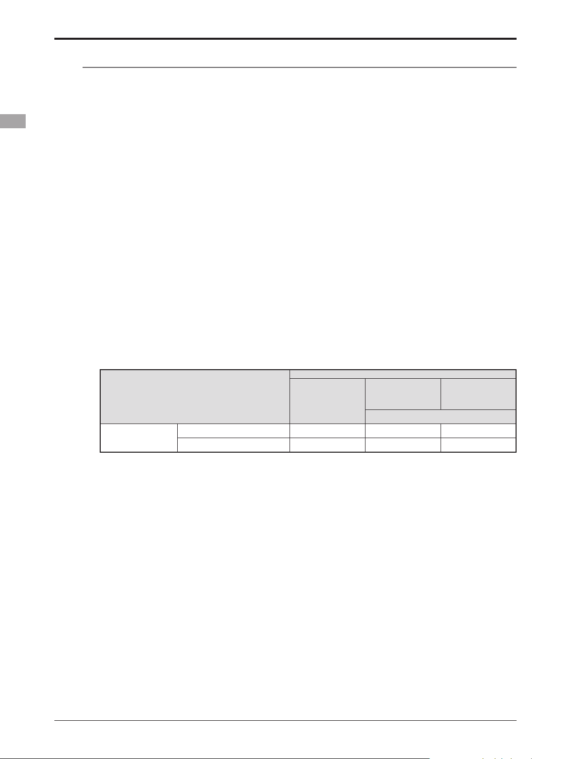
T8FGS-2.4GHz system and receiver compatibility
Receiver
T8FGS 2.4G System
R6004FF, R616FFM,
Transmitter
Multi-ch mode (MLT2/MULT) — — Okay
7-ch mode Okay Okay —
(*)Since these receivers have few ports, S.BUS is used for them when using many channels.
R606FS
R6106HF/HFC
R607FS, R617FS
R6203SB,R6203SBE,R6303SB,R6303SBE(
R608FS, R6208SB,
R6108SB
R6014FS/HS
)
*
Model types
Six swash types are available for helicopters. Six types of main wings and three types of tail wings are
available for airplanes and gliders. Functions and mixing functions necessary for each model type are set in
advance at the factory.
Data input
Large graphic LCD and new type Touch Sensor substantially improve ease of setup.
Stick
New stick design with improved feel, adjustable length and tension.
Ni-MH battery
T8FGS is operated by a 7.2 V/1,700 mAh Nickel-Metal Hydride battery.
SD card (Secure Digital memory card) (Not included)
Model data can be saved to an SD card (32MB-2GB). When T8FGS transmitter software files are
released, the software can be updated by using an SD card update.
<Before Use>
10
Page 11

Contents and Technical Specications
Your 8FG SUPER includes the following components:
(Specications and ratings are subject to change without notice.)
• T8FGS transmitter for airplanes or helicopters
• R6208SB Receiver
• HT6F1700B Ni-MH battery & Charger
• Switch harness
• Neck strap
*The set contents depend on the type of set.
Transmitter T8FGS
(2-stick, 14-channel, FASST-2.4G system)
Transmitting frequency: 2.4GHz band
Modulation: 2.4G 7-ch or 2.4G Multi-ch, switchable
Power supply: 7.2V HT6F1700B Ni-MH battery
Receiver R6208SB
(FASST-2.4G system, dual antenna diversity, S.BUS system)
Power requirement: 3.7V~7.4V battery or regulated
output from ESC, etc. (*1)
Size: 0.98 x 1.86 x 0.56 in. (24.9 x 47.3 x 14.3 mm)
Weight: 0.49 oz. (13.8g)
(*1) When using ESC's make sure that the regulated
output capacity meets your usage application.
Usage condition on "High Speed mode"
(R6208SB)
(Suggested Servo for use with your 8FG SUPER system)
Servo S9252 (Digital servo)
Control system: Pulse width control, 1.52 ms neutral
Power requirement: 4.8 V (from receiver)
Output torque: 91.7 oz.-in. (6.6 kg-cm) at 4.8V
Operating speed: 0.14 sec/60 at 4.8V
Size: 1.57 x 0.79 x 1.44 in. (40 x 20 x 36.6 mm)
Weight: 1.76 oz. (50 g)
Servo S9255 (Digital servo)
Control system: Pulse width control, 1.52 ms neutral
Power requirement: 4.8 V (from receiver)
Output torque: 125.0 oz.-in. (9.0 kg-cm) at 4.8V
Operating speed: 0.16 sec/60 at 4.8V
Size: 1.57 x 0.79 x 1.44 in. (40 x 20 x 36.6 mm)
Weight: 1.94 oz. (55 g)
Servo S3151 (Standard, Digital servo)
Control system: Pulse width control, 1.52 ms neutral
Power requirement: 4.8 V (from receiver)
Output torque: 43.1 oz.-in. (3.1 kg-cm) at 4.8V
Operating speed: 0.21 sec/60 at 4.8V
Size: 1.59 x 0.79 x 1.42 in. (40.5 x 20 x 36.1 mm)
Weight: 1.48 oz. (42 g)
CAUTION
When using the R6208SB in the high speed
(HS) mode, digital servos are required for
the rst six channels (1-6).
If an analog servo is connected to one of the first
six channels when in the high speed mode, the
servo will not function properly. Additionally,
while many peripheral devices will operate in either
the high speed or normal mode, some will not. If
there are any difficulties noted, please return the
reciever's operational mode to the "Normal" mode
to determine if this resolves the difculty.
If using the R6208SB in the high speed mode,
analog servos may be used for channels seven and
eight.
(For Operation Mode Selection, see p.26)
Servo S3001 (Standard, ball-bearing)
Control system: Pulse width control, 1.52 ms neutral
Power requirement: 4.8 - 6.0V (from receiver)
Output torque: 41.7 oz.-in. (3.0 kg-cm)
Operating speed: 0.22 sec/60
Size: 1.59 x 0.78 x 1.41 in. (40.4 x 19.8 x 36 mm)
Weight: 1.59 oz. (45.1g)
<Before Use>
11
Page 12

The following additional accessories are available from your dealer. Refer to a Futaba catalog for
more information:
• HT6F1700B Transmitter battery pack - the (1700mAh) transmitter Ni-MH battery pack may be easily
exchanged with a fresh one to provide enough capacity for extended ying sessions.
• Trainer cord - the optional training cord may be used to help a beginning pilot learn to fly easily by
placing the instructor on a separate transmitter. Note that the T8FGS transmitter may be connected to
another T8FGS system, as well as to any other models of Futaba transmitters. The T8FGS transmitter
uses one of the three cord plug types according to the transmitter connected. (Refer to the description at
the TRAINER function instructions). The part number of this cord is: FUTM4405.
• Neckstrap - a neckstrap may be connected to your T8FGS system to make it easier to handle and improve
your ying precision since your hands won’t need to support the transmitter’s weight.
• Y-harnesses, servo extensions, etc - Genuine Futaba extensions and Y-harnesses, including a heavy-duty
version with heavier wire, are available to aid in your larger model and other installations.
• Gyros - a variety of genuine Futaba gyros is available for your aircraft or helicopter needs.
• Governor (GY701) - for helicopter use. Automatically adjusts throttle servo position to maintain a
constant head speed regardless of blade pitch, load, weather, etc.
• Receivers - various models of Futaba receivers may be purchased for use in other models. (Receivers for
FASST-2.4GHz Multi-ch mode and 7-ch mode types are available.)
• Optional Charger - Futaba CR-2000 Ni-MH/Ni-Cd Transmitter/Receiver Battery Charger.
<Before Use>
12
Page 13

Transmitter controls
●Monitor LED
●Switch (SA,SB,SE,SF)
●Antenna
●Carring Handle
●Volume (LD,RD)
●Switch (SC,SD,SG,SH)
●Slide Lever (LS)
●Stick
(J3)
(J4)
●Digital Trim (T3,T4)
●Power Switch
●Neck Strap Attachment
●LCD Display
●Slide Lever (RS)
●Stick
(J2)
(J1)
●Digital Trim (T1,T2)
●SensorTouch
(SYS, LNK, MDL,
EXIT, RTN)
TM
<Before Use>
13
Page 14
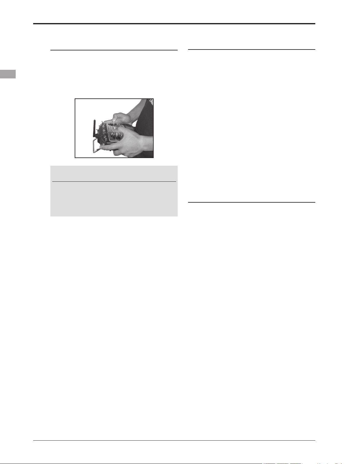
Transmitter's Antenna:
As with all radio frequency transmissions, the
strongest area of signal transmission is from the
sides of the transmitter's antenna. As such, the
antenna should not be pointed directly at the model.
If your flying style creates this situation, easily
move the antenna to correct this situation.
CAUTION
Please do not grasp the transmitter's
antenna during ight.
Doing so may degrade the quality of the RF
transmission to the model.
Monitor LED display
The status of the transmitter is displayed by LED
at the bottom left and right sides of the "T8FG
SUPER" logo.
LED (Left)
Displays the "non-default condition" warning.
• Blinking
Power switch is turned on when any
condition switch is activated (in the ON
state).
LED (Right)
Displays the state of radio frequency
transmission.
• Off
Radio waves are in the OFF state.
• On
Radio waves are being transmitted.
Switch (SA-SH)
(Switch Type)
• SA : 3 positions; Alternate; Short lever
• SB : 3 positions; Alternate; Long lever
• SC : 3 positions; Alternate; Long lever
• SD : 3 positions; Alternate; Short lever
• SE : 3 positions; Alternate; Short lever
• SF : 2 positions; Alternate; Long lever
• SG : 3 positions; Alternate; Short lever
• SH : 2 positions; Momentary; Long lever
<Before Use>
14
*You can choose switch and set the ON/OFF-direction in the
setting screen of the mixing functions.
Page 15
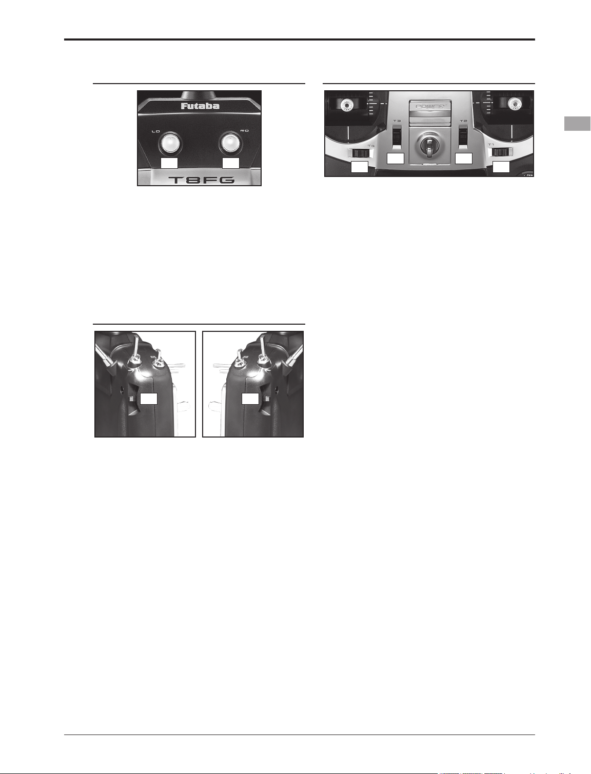
Volume
Digital Trim
LD RD
Volume LD and RD:
The volume LD and RD knobs allow analog
input.
*The T8FGS transmitter beeps when the volume knob
reaches the center position.
*You can use each setting screen of the mixing functions to
select volumes and dene the direction of a movement.
Slide Lever
RSLS
LS (Left), RS (right):
The slide lever LS and RS offer analog input.
*The T8FGS transmitter beeps when the lever comes to the
center.
*You can select a slide lever and set the movement direction
on the setting screen of mixing functions.
T4
T2T3
T1
Digital Trim T1, T2, T3 and T4:
This transmitter is equipped with four (4) digital
trims. Each time you press a trim button, the trim
position moves one step. If you continue pressing it,
the trim position starts to move faster. In addition,
when the trim position returns to the center, the
tone will change. You can always monitor trim
positions by referencing the LCD screen.
*You can select the trim step amount and the display unit
on the home screen on the T1-T4 setting screen within the
linkage menu.
Note: The trim positions you have set will be stored in the
non-volatile memory and will remain there.
<Before Use>
15
Page 16
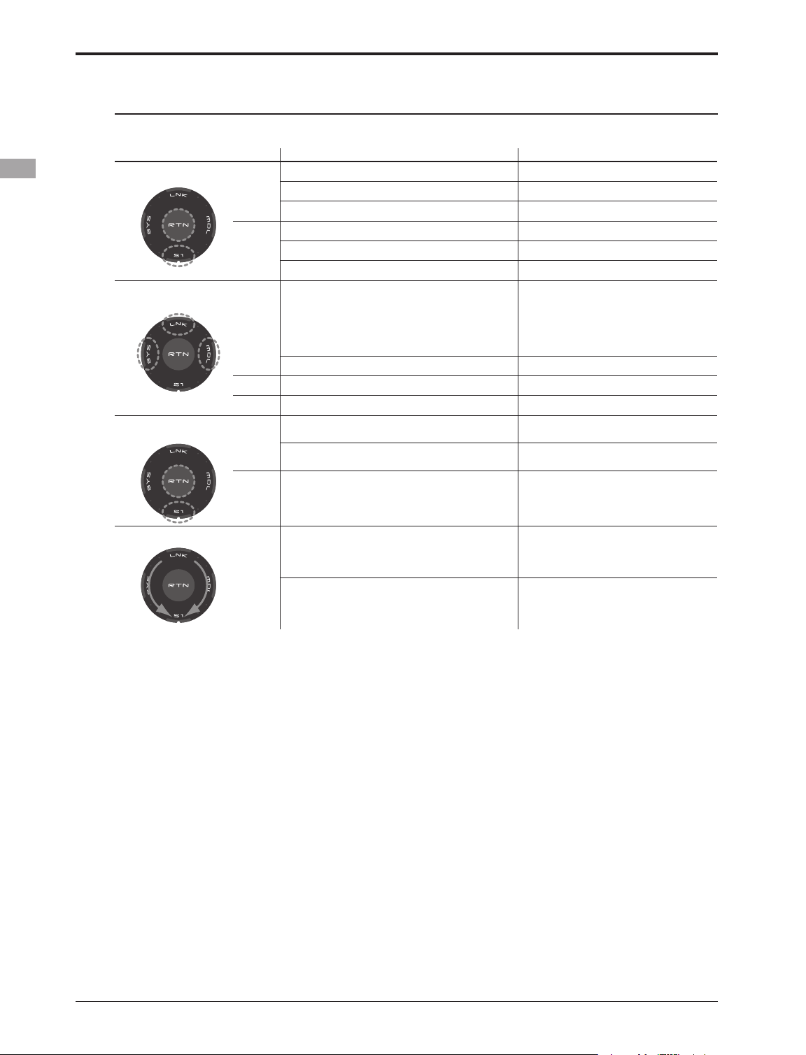
Touch sensor operation
Data input operation is performed using the touch sensor.
SensorTouch™ operation Condition Working
• Short 'tap'
• Two short 'taps'
• Touch and hold for
one (1) second.
If the screen has more than one page. (Ex. P-MIX screen)
If the screen have only one (1) page. The cursor moves to the top of page.
S1
If the input data mode with blinking the setting data. The input data is canceled.
At the moving cursor mode. Change to the input data mode.
At the input data mode. Change to the moving cursor mode.
RTN
At the input data mode with blinking the setting data. The data is entered.
Home screen, System menu, Linkage Menu, Model
menu, Selecting ON/OFF Switch, USER NAME,
MODEL NAME, DISPLAY, INFO, MODEL SELECT,
MODEL TYPE, FREQUECY, DATA RESET, TIMER,
SYS
Selecting Control, Selecting Function, SERVO
MONITOR
At all screens except those noted above. Jump to Servo Monitor screen directly.
At all screens Jump to Linkage Menu screen directly.
LNK
At all screens Jump to Model Menu screen directly.
MDL
At the HOME screen Key lock On or Off
S1
Except the HOME screen Jump to Home Screen directly.
The cursor moves to the top of next page.
Jump to System Menu screen directly.
At the input data mode without blinking the setting
RTN
data.
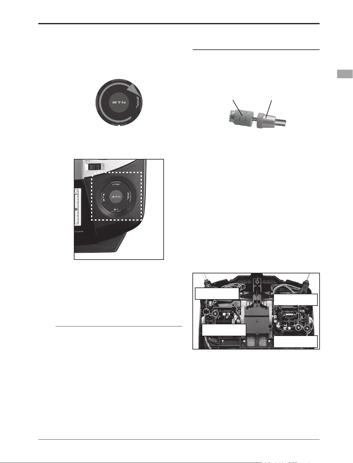
• Scrolling
Lightly circling the outside edge of the RTN button. The cursor moves accordingly.
Outline
of
“RTN”
During the data input mode. Increases or decreases values accordingly.
Movement of cursor, value input or mode selection
:
Movement of the cursor on the menu screen and
movement of the cursor among items on a setup
screen can be controlled by scrolling your finger
to the left and right in the direction of the arrow in
the scrolling diagram above. You can also go to the
next page, if there is a next page.
This scrolling technique is also used for data
input, value input, mode selection, and similar
operations. Examples include: Value, ON, OFF,
INH, ACT, etc.
RTN button:
Touch the RTN button when you want to open
a setup screen or to switch between cursor move
mode (reverse display) and data input mode (box
display).
This button can also be used as the enter button
when a confirmation message is displayed on the
screen, etc.
Reset to the initialized value.
S1 button:
When there is a next page on a menu screen or
setup screen, you can go to that page by touching
the S1 button. In this case, the cursor moves to the
screen title item of the page.
Exiting setup screen:
To end the operation on a setup screen and return
to the menu screen, move the cursor to the screen
title item and touch the RTN button.
To return to home screen directly, touch the S1
button for 1 second.
Alternatively, move the cursor to the screen title
item and touch the RTN button to return to the
home screen from a menu screen.
<Before Use>
16
Page 17
Note:
*Scroll operation: Circle your nger on the outside edge of
the RTN button. The sensors may mis-read your touch as a
reverse rotation if the circle is smaller, or performed on the
inside edge of the RTN button.
Stick Adjustment
Adjustment of the stick lever length
You can adjust the length of stick levers, as you
like. It is recommended to adjust the length of the
sticks in line with your hand size.
Lever Head
A
Lever Head
B
* The SensorTouch™ may not operate smoothly if your hand
is touching the surrounding case parts. As such, please
make sure that the tip of your nger is actually operating the
SensorTouch™.
*If the SensorTouch™ does not register your input, please
try again after lightly tapping your nger on the sensor once
again.
* Do not operate the SensorTouch™ with gloves worn. The
SensorTouch™ might not react.
1. Hold the lever head "B" and turn the lever
head "A" counter-clockwise. The lock will be
released.
2. Turn the lever-head "A" clockwise as you hold
the lever-head "B" after placing it as you like.
Adjustment of stick lever tension
The tension of the self-return type stick lever can
be adjusted.
1. First, Remove the battery cover on the
bottom of the transmitter. Next, unplug the
battery wire and remove the battery from
the transmitter.
2. Next, using a screwdriver, remove the five
screws that hold the transmitter's rear case
in position, and put them in a safe place.
Gently ease off the transmitter's rear case.
Now you'll see the view shown in the figure
below.
•Stick Tension (J2)
(Mode 2)
•Stick Tension (J4)
(Mode 1/2)
CAUTION
The touch sensor might not operate by
receiving the spark noise generated from
the gasoline engine etc. In this case, please
operate your transmitter from the noise
source apart.
•Stick Tension (J1)
(Mode 1/2)
2. Use a small Phillips screwdriver to adjust the
spring strength as you prefer by turning the
adjusting screw of the stick you want to
adjust.
*Turning the screw clockwise increases the tension.
CAUTION: If you loosen the screw too much,
the stick may not operate because it is
caught internally.
3) At the end of adjustment, re-install the rear
case.
•Stick Tension (J3)
(Mode 1)
<Before Use>
17
Page 18
SD Card (Secure Digital memory card) (Not
included)
The T8FGS transmitter model data can be stored
by using any commonly found SD card. When
T8FGS transmitter update software is released, the
software is updated using an SD card. The T8FGS
is capable of using SD cards with a memory size
between 32MB and 2GB.
Caution
Be sure to turn off the power to the
transmitter before inserting or removing
the SD card.
As the SD card is a precision device, do not
use excessive force when inserting.
Restrictions when using an SD card
The following restrictions apply when using an
SD card:
*The SD card must first be initialized using the T8FGS
dedicated format. The SD card cannot be used as is without
formatting for the T8FGS.
*Initializing destroys all the data previously saved on the
card.
*An SD card formatted to the T8FGS cannot be written
directly from a PC by Windows Explorer, etc. The files
must be converted and written by the Futaba File System
software. Files are identified by number instead of name.
This special conversion software can be downloaded from
Futaba's web site at:
http://www.futaba-rc.com/sellsheets/downloads.html
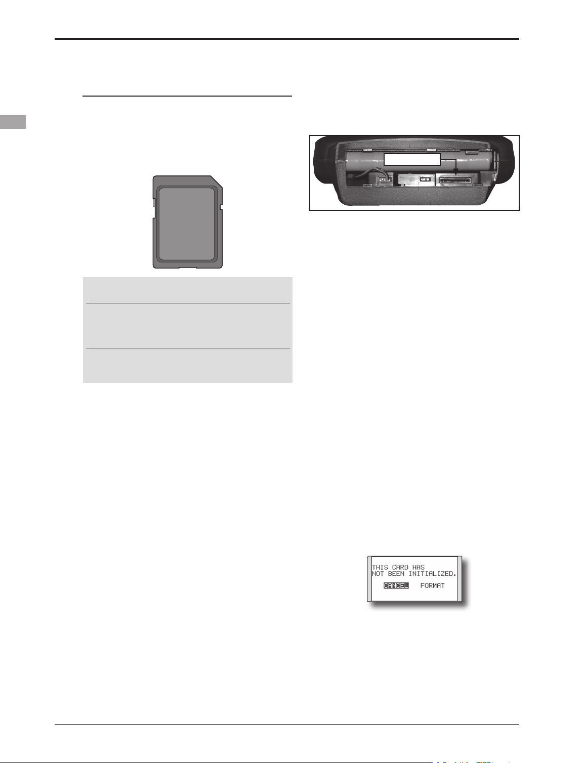
Inserting/removing the SD card
1. Turn off the transmitter power and then
open the battery cover at the bottom of the
transmitter.
2.
SD Card Slot
[Inserting the card]
Turn the SD card so that the front of the card
faces the rear of the transmitter and slide the
card into the card slot.
*Push in the card until it is rmly seated in the card slot.
[Removing the card]
When the SD card is pressed in once again,
the card will be released from the card slot.
and can be removed.
3. Close the battery cover.
SD card initialization
To use an SD card with the T8FGS, the card
must first be formatted. Once formatted, the card
does not have to be reformatted. Formatting is
performed by the T8FGS.
[IMPORTANT] When an SD card is formatted
for the T8FGS, all pre-existing data is
destroyed. Do not format a card containing
important data.
[Formatting procedure]
1. Insert the SD card into the SD card slot of the
T8FGS.
2. Turn on the T8FGS power. When an
unformatted card is inserted into the T8FGS,
the screen shown below appears.
<Before Use>
18
3. If the T8FGS is ready to format, move the
cursor to [FORMAT] and touch the RTN
button. (To cancel formatting, move the
cursor to [CANCEL] and touch the RTN
button.)
Page 19
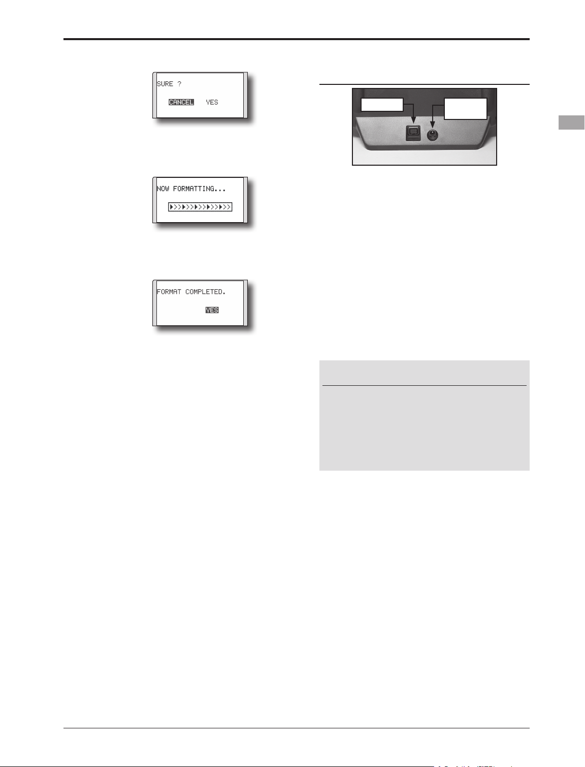
Connector/Plug
4. Move the cursor to [YES] and touch the RTN
button.
* Formatting starts. During formatting, the [NOW
FORMATTING...] message is displayed.
*When formatting is completed, The [FORMAT
COMPLETED] message is displayed. Depending on the
card capacity and speed, formatting may take as long as
several minutes.
[IMPORTANT] Do not turn off the power
until the [FORMAT COMPLETED] message is
displayed.
5. End formatting by touching the RTN button.
SD card reader/writer
Saving model data and update files (released
from Futaba) into the SD card, you can then
transfer those files to your T8FGS transmitter.
Equipment for reading and writing SD cards is
available at most electronics stores.
•Trainer •Battery
charge
Connector for trainer function
When you use the trainer function, connect the
optional trainer cable between the transmitters for
teacher and student.
*You can set the trainer function on the Trainer Function
screen in the System menu.
Connector for battery charger
This is the connector for charging the Ni-
MH battery HT6F1700B that is installed in the
transmitter. Do not use any other chargers except
the attached special charger corresponding to Ni-
MH battery.
Warning
Do not connect any other chargers except
the special charger to this charging
connector.
*If you take out the Ni-MH battery HT6F1700B from
the transmitter, you can use the optional quick charger
CR-2000 corresponding to Ni-MH battery.
Stored data
If you have a problem saving or reading data
after a long period of use, we suggest obtaining a
new SD card to avoid further difculties.
*Futaba is not responsible for compensating any failure or
damage to the data stored in the memory card. As such, we
suggest that you maintain a backup of your important data
contained on your SD card.
<Before Use>
19
Page 20
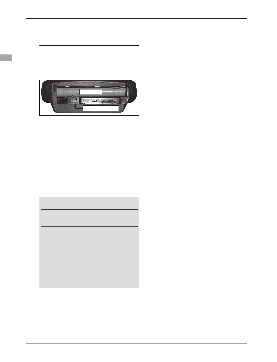
Installation and Removal of the HT6F1700B
Transmitter Battery
Attachment of the battery
1. Slide the battery cover on the bottom of the
transmitter toward the right side and open it.
2. Install the battery in the holder.
3. Connect the battery connector.
•Battery
•Battery Connector
4. Close the battery cover completely.
Battery Removal
Note: If you remove the battery while the
power is on, the data you have set will not
be saved.
1. Open the battery cover.
2. Disconnect the battery connector.
3. Pull up the right side of the battery and
remove the battery.
4. Close the battery cover completely.
Warning
Be careful not to drop the battery.
Never disconnect the battery connector
from the T8FGS transmitter after turning
off the power until the screen is completely
blank and the transmitter has shut down
completely.
* Internal devices such as memories may be damaged.
* If there is any problem, the message "Backup Error" will
be shown the next time when you turn on the power of
the transmitter. Do not use the transmitter as it is. Send it
to the Futaba Service Center.
<Before Use>
20
Page 21
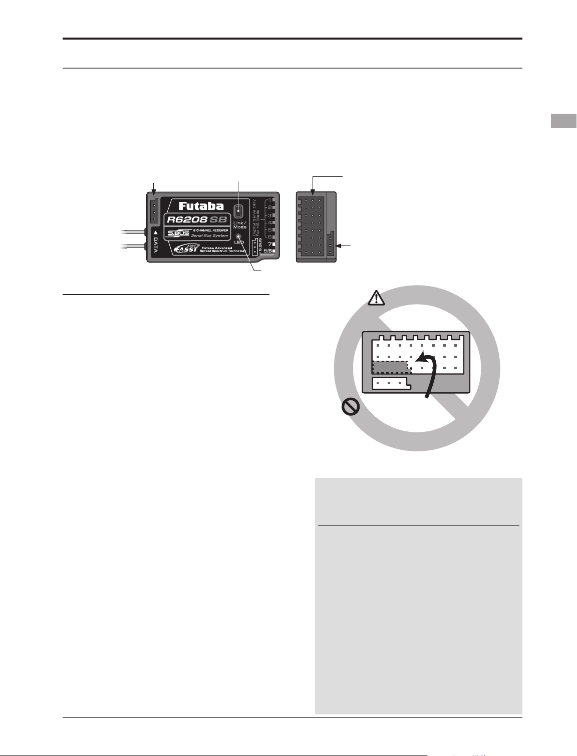
Receiver nomenclature
Before using the receiver, be sure to read the precautions listed in the following pages.
The R6208SB has an S.BUS system output port and a conventional system channel output. It can also be used
with conventional system servos, etc. in addition to S.BUS system compatible servos and gyros, etc.
In addition, the operating mode (high-speed mode/normal mode) can be selected.
DATA p o r t
Link/Mode switch
LEDR6208SB
Connector
"1 through 6": outputs for the channels 1 through 6.
(Digital servo only in the High Speed mode.)
"7", "8": outputs for the channels 7 and 8.
(Analog or digital servos regardless of mode.)
"B": connector for the power.
"S.BUS": output for the S.BUS system.
The R6208SB has two(2) operation modes as
shown below.
Receiver Normal mode/High Speed mode
The "Normal mode" accepts any type of servos
or peripherals as the frame rate of the output is
14ms. The "High Speed mode" only accepts digital
servos for outputs from 1ch to 6ch. This includes
the BLS series, and most peripheral equipment
such as gyros and brushless ESCs. The frame rate
of the outputs is 7ms. The outputs from 7ch to 8ch
allow the use of any type of servos as the frame
rate of these outputs are still 14ms ever in the High
Speed mode.
• Channel outputs for conventional
system (1 to 8)
• Battery terminal (B)
• S.BUS Port (S.BUS)
Danger
Receiver
Don't connect neither a switch
nor a battery in this way.
* It will short-circuit, if it connects in this way.
A short circuit across the battery terminals may
cause abnormal heating, fire and burns.
Usage condition on "High Speed mode"
CAUTION
When using the R6208SB in the high speed
(HS) mode, digital servos are required for
the rst six channels (1-6).
If an analog servo is connected to one of the first
six channels when in the high speed mode, the
servo will not function properly. Additionally,
while many peripheral devices will operate in either
the high speed or normal mode, some will not. If
there are any difficulties noted, please return the
reciever's operational mode to the "Normal" mode
to determine if this resolves the difculty.
If using the R6208SB in the high speed mode,
analog servos may be used for channels seven and
eight.
(For Operation Mode Selection, see p.26)
<Before Use>
21
Page 22
BASIC OPERATION
Battery Charging
Before charging batteries, read the "Cautions for handling battery and battery charger" in the section "Ni-
MH/Ni-Cd Battery Safety and Handling Instructions".
How to charge the Ni-MH battery HT6F1700B
for the transmitter
Danger
The Ni-MH battery HT6F1700B is only for
your T8FGS, T8FG and T12FG. Do not use
this battery for other equipment.
Be sure to use the attached special charger to
charge the battery.
*If you take out the Ni-MH battery HT6F1700B from the
transmitter, you can use the optional quick charger CR-2000
corresponding to Ni-MH battery.
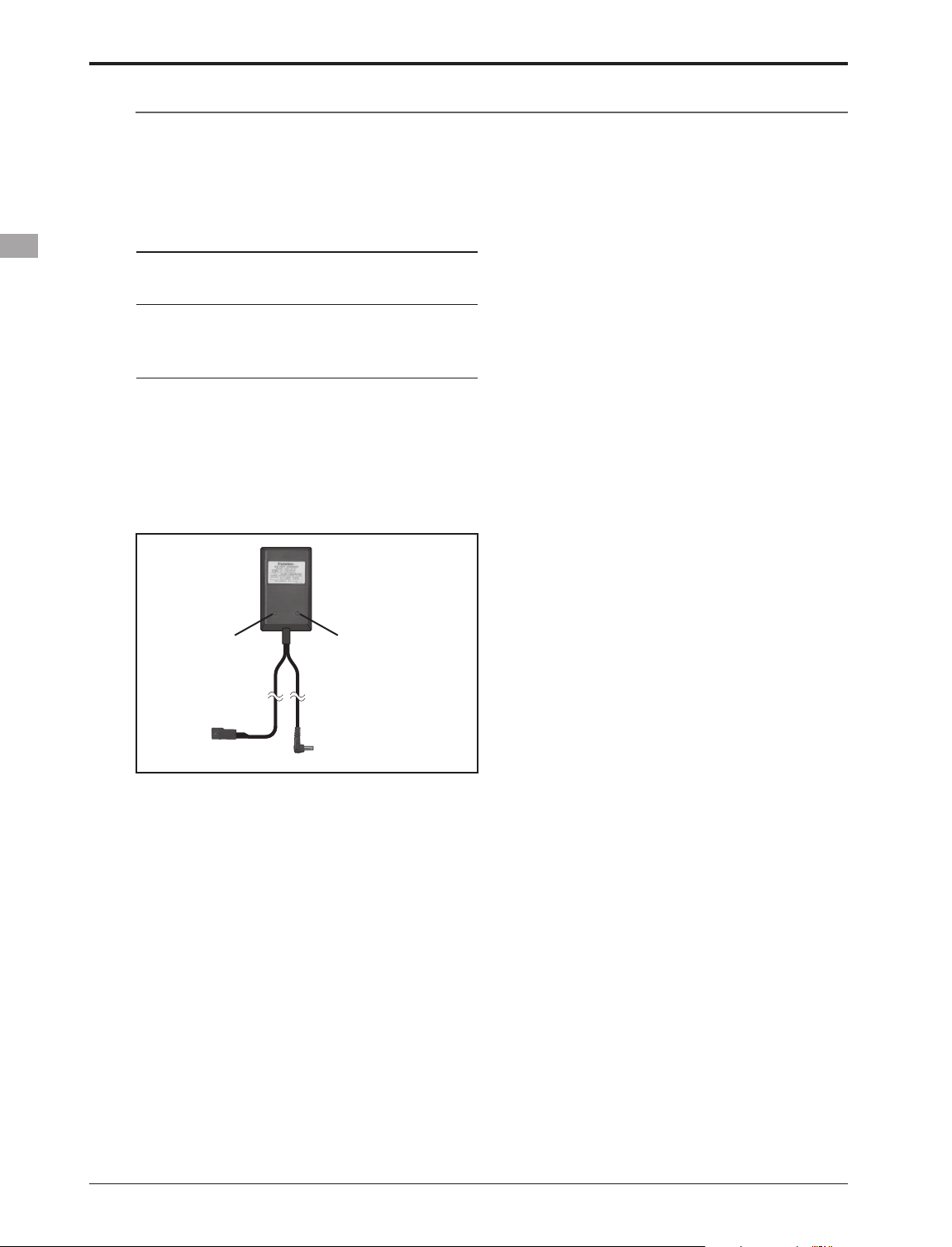
[Method of charging battery]
●Special charger
*Connect to AC outlet
specified.
Receiver Batt.
Charging display
Transmitter Batt.
Charging display
*Battery charging will not automatically stop. Remove the
battery and transmitter from the charger and remove the
charger from the wall socket.
*It is recommended to reactivate the battery by cycling
several times if the battery has not been used for a long
period.
*In the case of Ni-MH/Ni-Cd batteries, you may find poor
performance of the battery if you have used the battery
only for a short period or if you repeat charging while the
battery is not fully discharged. It is suggested to discharge
the battery to the recommended level after use. It is also
recommended to charge the battery just before use.
To T8FGS charge
connector
1. Connect the special charger to the wall
socket (AC outlet).
2. Connect the connectors to the T8FGS
charging connector.
*Conrm that the charging indicator, LED lamp, is on.
*Turn off the transmitter while charging the battery.
3. Remove the battery after 15 hours.
<Basic Operation>
22
Page 23
How to turn transmitter power ON/OFF
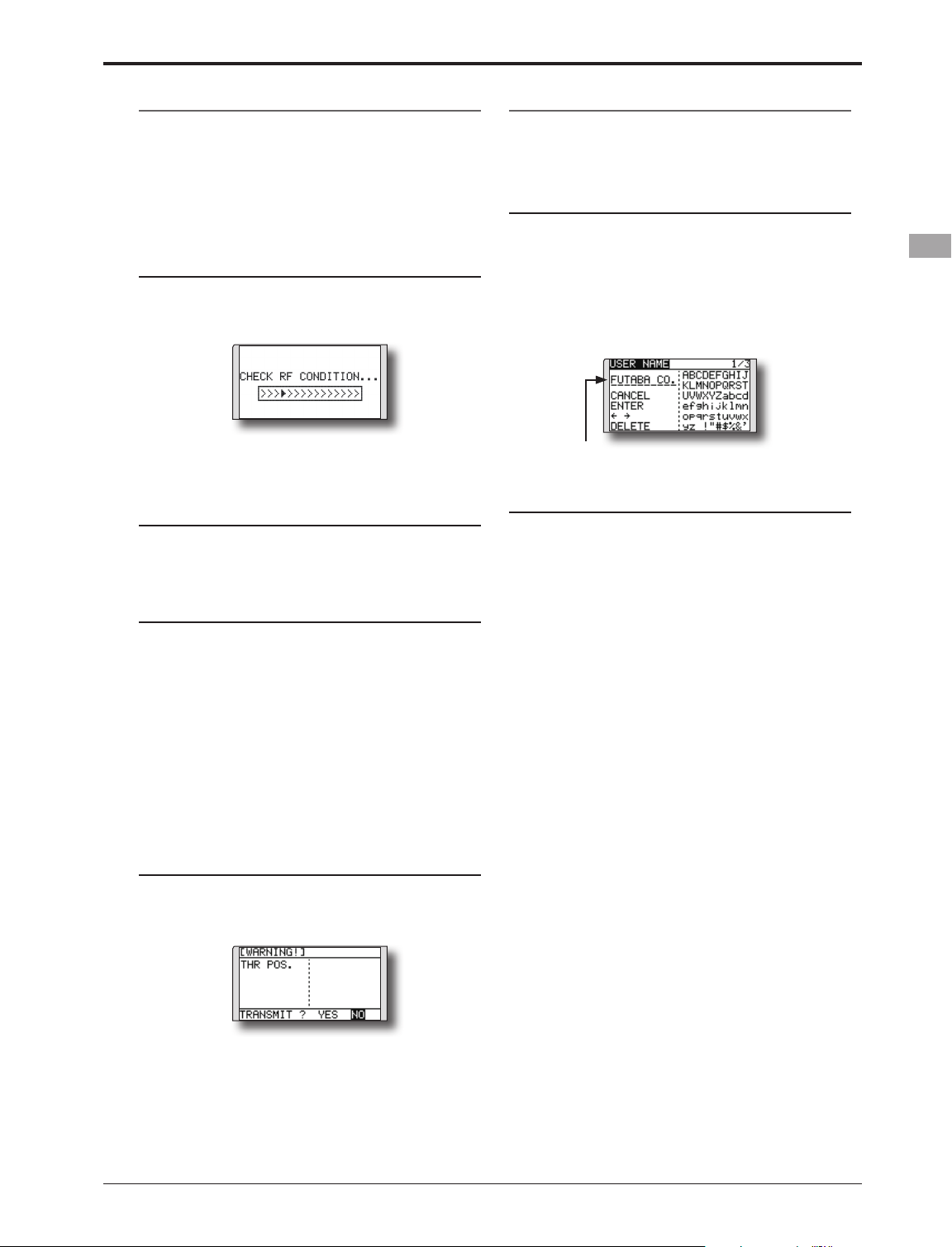
When turning on the power, the T8FGS
transmitter will begin emmiting RF automatically
after it conrms the surrounding RF conditions.
The T8FGS transmitter also offers the ability to
auto shut-down.
When turning on the power of the transmitter
1. Turn on the power switch of the transmitter.
*The message "CHECK RF CONDITION" is displayed for a
moment. At the same time the left LED monitor blinks.
Registration of the user's name
If so desired, the T8FGS transmitter can
indicate the owner's name.
User's name setup screen
1. Turn on the power of the transmitter.
*The home screen appears.
2. Lightly touch the SYS button twice rapidly
and the System menu appears.
2. Select [USER NAME] in the System menu and
touch the RTN button.
*The user name set up screen appears.
2. Then, you will see the home screen and the
transmitter begins to emit radio waves.
*The left and right LED monitors will change to solid red.
How to stop the transmitter
1. Turn off the power switch of the transmitter.
*The transmitter shuts down at once.
Low battery alarm and auto shut-down
When the battery voltage reaches 6.8V, an
audible alarm will sound. Land your aircraft
immediately.
When the battery voltage reaches 5.5V, the
transmitter will be turned off automatically.
*If you do not operate the transmitter (or move a stick,
knob, switch or digital trim) for 30 minutes, the message
"PLEASE TURN OFF POWER SWITCH" is displayed and
an audible alarm will sound.
Warning display at power ON (Airplane/
Helicopter)
When the throttle stick at power ON is at the
high side (1/3 or more the same as throttle cut
operation), a warning is displayed.
Input Box
*Current user name is displayed.
Changing the user name
1. Change the user name as described below:
[Moving cursor in input box]
Select [←] or [→], and touch the RTN button.
[Deleting a character]
When [DELETE] is selected and the RTN button
is touched, the character immediately after
the cursor is deleted.
[Adding a character]
When a character is selected from the
character list and the RTN button is touched,
that character is added at the position
immediately after the cursor.
*A name of up to 10 characters long can be entered as the
user name. (A space is also counted as one character.)
2. At the end of input, select [ENTER] and tuoch
the RTN button. (To terminate input and
return to the original state, select [CANCEL]
and touch the RTN button.)
* When the throttle stick is returned to SLOW, the warning
display goes off.
<Basic Operation>
23
Page 24
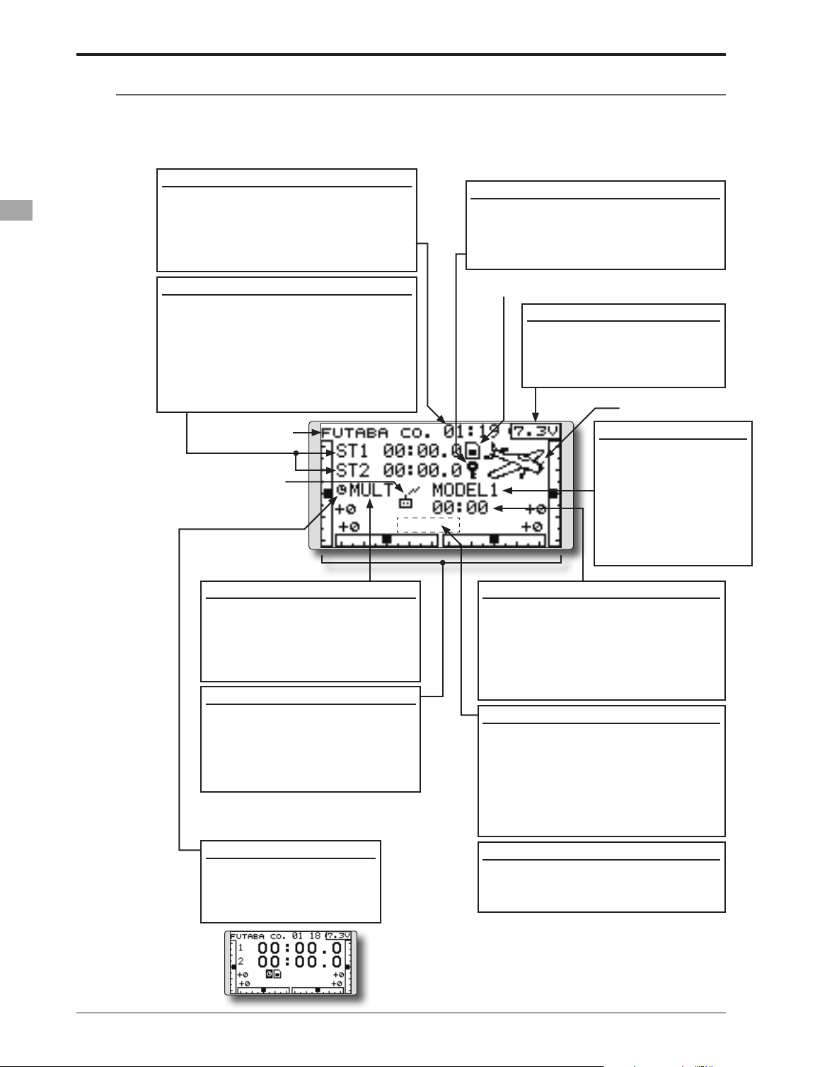
Home screen
Use the touch sensor to select the following display area to call each setting screen, and touch the RTN
button. The setting screen appears.
System timer
• This shows the accumulated time since
the latest reset. (Hour):(Minute)
• Use the cursor to highlight this, then
touch the RTN button for one second
to reset the system timer.
Up/Down timer (ST1, ST2)
• Timer is displayed here.
Touch the RTN button at the [xx]:[xx.x]
item to start/stop the timer.
• Use the cursor to highlight this, then
touch the RTN button at the ST1 or ST2
item to call the timer set-up screen.
*See the description at the back of this manual.
User's name
RF indicator
Key lock
• Touch the S1 button for one second
to lock/unlock the key operation.
In the key lock mode the key icon is
displayed here.
SD card indicator
Battery Indicator
• When the battery voltage
reaches 6.8V, the alarm will
beep. Land your aircraft
immediately.
Model type
Model Name
• The model name that
is currently used is
displayed here.
• Use the cursor to
highlight this, then
touch the RTN button
to call the model
select set-up screen.
FASST mode
• FASST mode is displayed here.
• Use the cursor to highlight this,
then touch the RTN button
to call the frequency set-up
screen.
Digital trim (T1 to T4)
• Trim position is displayed here.
• You can select the display unit
on the home screen on the
T1-T4 setting screen within the
linkage menu.
2nd Home screen
• Touch the RTN button at
the clock icon to call the
nd
2
home screen (large
size timer).
Model timer
• This shows the accumulated time
since the latest reset. (each model)
(Hour):(Minute)
• Use the cursor to highlight this,
then touch the RTN button for one
second to reset the model timer.
Condition name (Heli/Glider)
• In the normal condition, move the
cursor to the condition name and
touch the RTN button. The condition
name is changed and blinked.
It is possible to operate the
digital trim other than the normal
condition.
VPP condition # (Air)
• When VPP function is assigned to a
channel, the current VPP condition
# is displayed here.
<Basic Operation>
24
Page 25
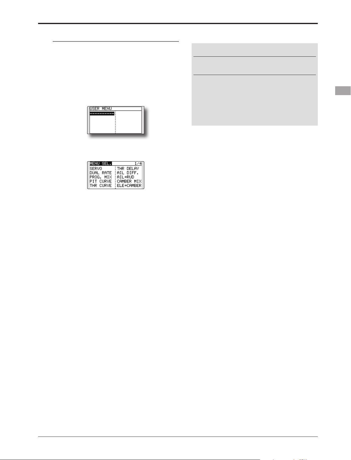
User Menu
A user menu which allows the user to customize
and display frequently used functions has been
added.
1. When the S1 button on the home screen is
touched, the user menu appears.
* Return to the home screen by touching the S1 button while
the user menu is being displayed.
2. When the cursor is moved to the "---------" button and the RTN button is touched ,the
menu selection screen appears.
3. When the cursor is moved to the setting
screen you want to register at the user menu
and the RTN button is touched, that setting
screen is registered at the user menu.
4. The registered setting screen can be called
by moving the cursor to it and touching the
RTN button.
Warning
Be sure to confirm the model name before
ying your aircraft.
Check the battery voltage as often as possible
and try to charge the battery earlier. If the
battery alarm makes a sound, land your
aircraft immediately.
*You can adjust the LCD contrast by the display setting in
the System menu.
*When you want to delete a registered screen from the user
menu, press the RTN button for one second.
<Basic Operation>
25
Page 26
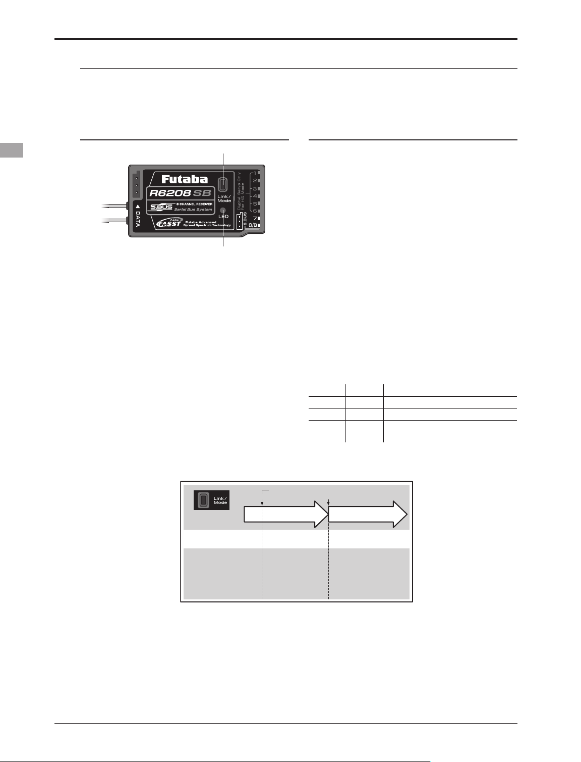
Operation Mode Select (R6208SB)
The receiver operation mode is on "Normal mode" from factory shipping. To change the mode, please
adhere to the following steps:
Changing the operation mode
Link/Mode Button
LED
1. Turn off the receiver.
2. Press and hold the Link/Mode button and
turn on the receiver. Continue holding the
button for more than one(1) second. The LED
begins ashing to indicate the current status.
3. Release the button.
4. Turn off the receiver.
By doing so, the receiver will change modes.
Conrming the operation mode
Please check the operation mode by observing
the LED when turning on the receiver.
If possible ensure that there's no FASST
transmitter in operation near the receiver.
1. When the receiver is turned on:
Red when on "Normal mode"
Initially flashes green and Red (making
Orange) when in "High Speed mode". After
two(2) seconds, change to Red.
If there are additional FASST transmitters turned
on near the receiver, the LED may show the above
status for a brief moment before changing to the
status indication as shown in the "LED indication"
table below.
LED Indication (R6208SB)
Green Red Status
Off Solid No signal reception
Solid Off Receiving signals
Blink Off
Receiving signals but ID is
unmatched
<Basic Operation>
26
Press and Hold time
(Function)
Status)
(LED
(Operation Mode Select)
Turn on the receiver.
0 sec. 1 sec.
0 to 1 sec. More than 1 sec.
No function
Showing the CURRENT
mode with blink.
Red Blink = Normal
Green/Red Blink =
High Speed
To change the mode between
Normal and High Speed
Solid as the mode changed.
Red Solid = Normal
Green/Red Solid = High
Speed
(Become Red after one (1)
second)
Page 27
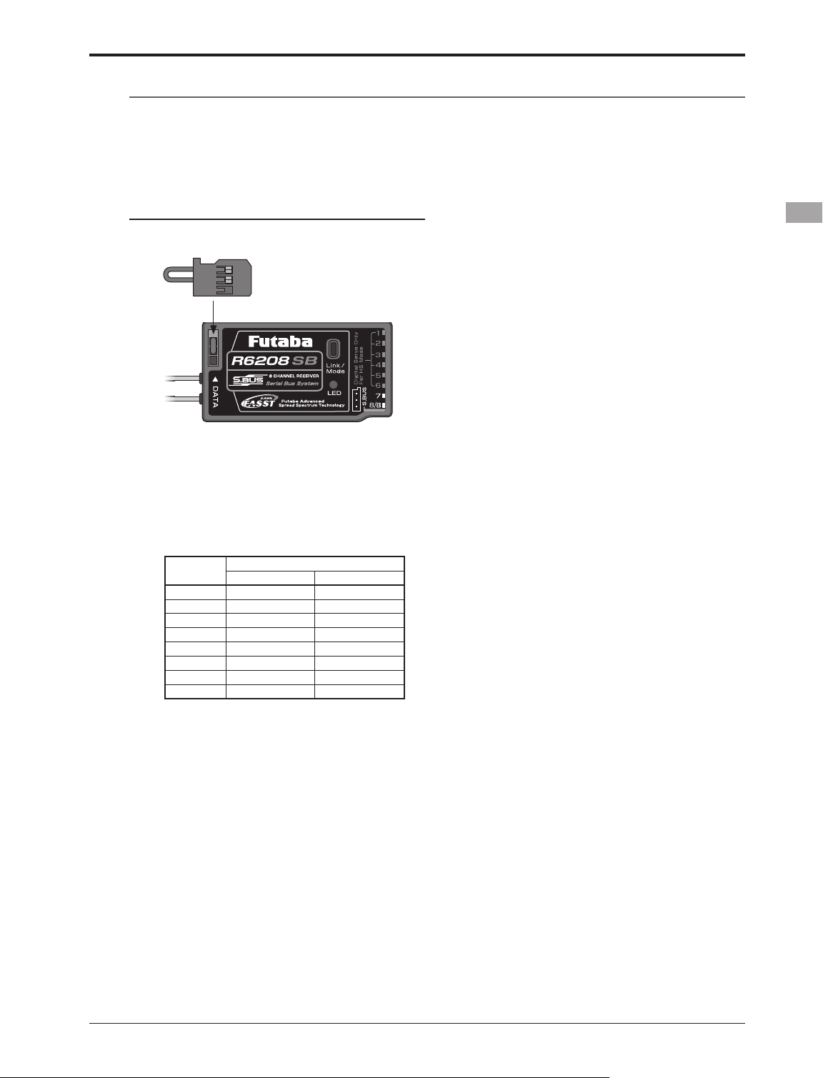
S.BUS Servo Channel Setting (R6208SB)
S.BUS servo channel setting can be performed by using an S.BUS compatible receiver, an SBC-1
channel changer or CIU-2 USB serial interface. To set the channel by using your R6208SB, please adhere
to the following steps:
Channel setting
1. Connect the accessory short-plug to the
DATA port of the receiver.
Short-plug
(accessory)
* Connect the short-plug to the DATA port only when an
S.BUS servo channel is set. Normally do not connect the
plug.
2. Connect an S.BUS servo to the conventional
system output connector(1 to 8)
corresponding to the channel you want to
set.
Output
connector
1 1 9
2 2 10
3 3 11
4 4 12
5 5 13
6 6 14
7 7 15
8 8 16
* Channel setting mode A (ch1 to 8 setting mode) or channel
setting mode B (ch9 to 16 setting mode) can be set.
3. Turn on the receiver.
* At once when turning on the receiver, the channel setting is
completed in mode A.
(To switch to mode B, press the Link/Mode
button until the red and green LED starts to
blink simultaneously. The channel setting is
completed in mode B.)
* The LED corresponding to the setting mode blinks.
Mode A: Red blinks 3 times
Mode B: Green blinks 3 times
4. Turn off the receiver.
Channel setting
Mode A Mode B
<Basic Operation>
27
Page 28
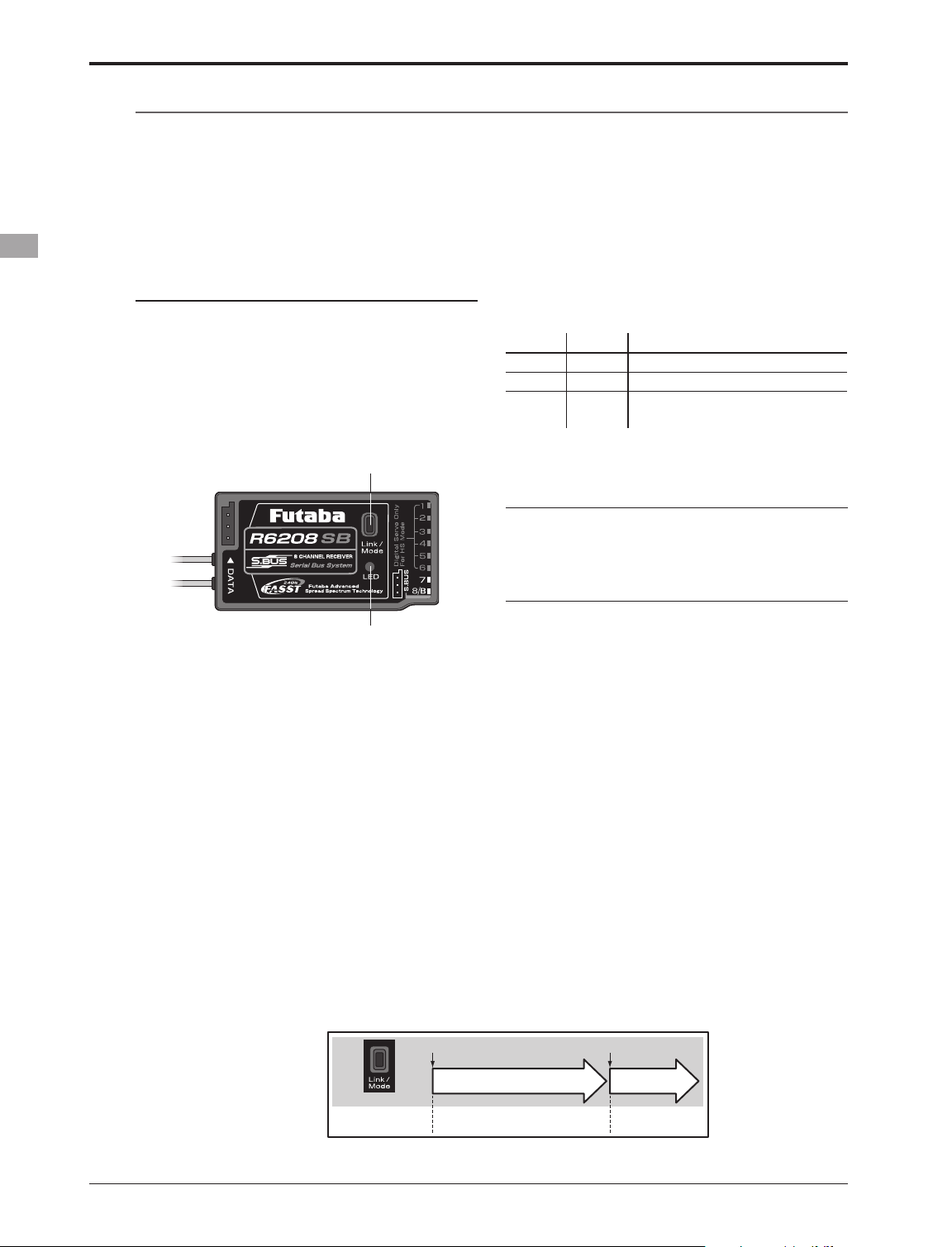
Easy Link (T8FGS/R6208SB)
Each transmitter has an individually assigned, unique ID code. In order to start operation, the receiver
must be linked with the ID code of the transmitter with which it is being paired. Once the link is made,
the ID code is stored in the receiver and no further linking is necessary unless the receiver is to be used
with another transmitter. When you purchase additional R6208SB receivers, this procedure is necessary;
otherwise the receiver will not work.
Link procedure
1. Place the transmitter and the receiver close
to each other within one (1) meter.
2. Turn on the transmitter.
3. Check the LED that is placed on the front
side of the transmitter to see if the RF signal is
active. When the right LED is ON solid, the RF
signal is being sent.
4. Turn on the receiver.
Link/Mode Button
LED Indication (R6208SB)
Green Red Status
Off Solid No signal reception
Solid Off Receiving signals
Blink Off
Receiving signals but ID is
unmatched
Warning
After the linking is done, please cycle receiver
power and check if the receiver to be linked is
really under the control by the transmitter to be
linked.
LED
5. Press down the Link/Mode button for more
than two seconds, and release the switch.
The receiver begins the linking operation.
6. When the linking is complete, the LED in the
receiver will change to solid green. Please
conrm that the servos are now operational
from your transmitter. Please refer to the
table below for the LED status of the
receiver's condition.
* If there are many FASST systems turned on around your
receiver, it might not link to your transmitter. In this case,
even if the receiver's LED stays solid green, unfortunately
the receiver might have established a link to one of other
transmitters. This is very dangerous if you do not notice
this situation. In order to avoid the problem, we strongly
recommend you to doublecheck whether your receiver is
really under control by your transmitter by giving the stick
input and then checking the servo response.
(Easy Link Operation)
0 sec. 2 sec.
Press and Hold
Do not perform the linking procedure with
motor's main wire connected or with the engine
operating as it may result in serious injury.
0 to 2 sec.
No function Re-link(ID set)
More than 2 sec.
<Basic Operation>
28
Page 29
Range Testing Your R/C System
It is extremely important to range check your models prior to each ying session. This enables you to
ensure that everything is functioning as it should and to obtain maximum enjoyment from your time ying.
The T8FGS transmitter incorporates a system that reduces its power output and allows you to perform such
a range check.
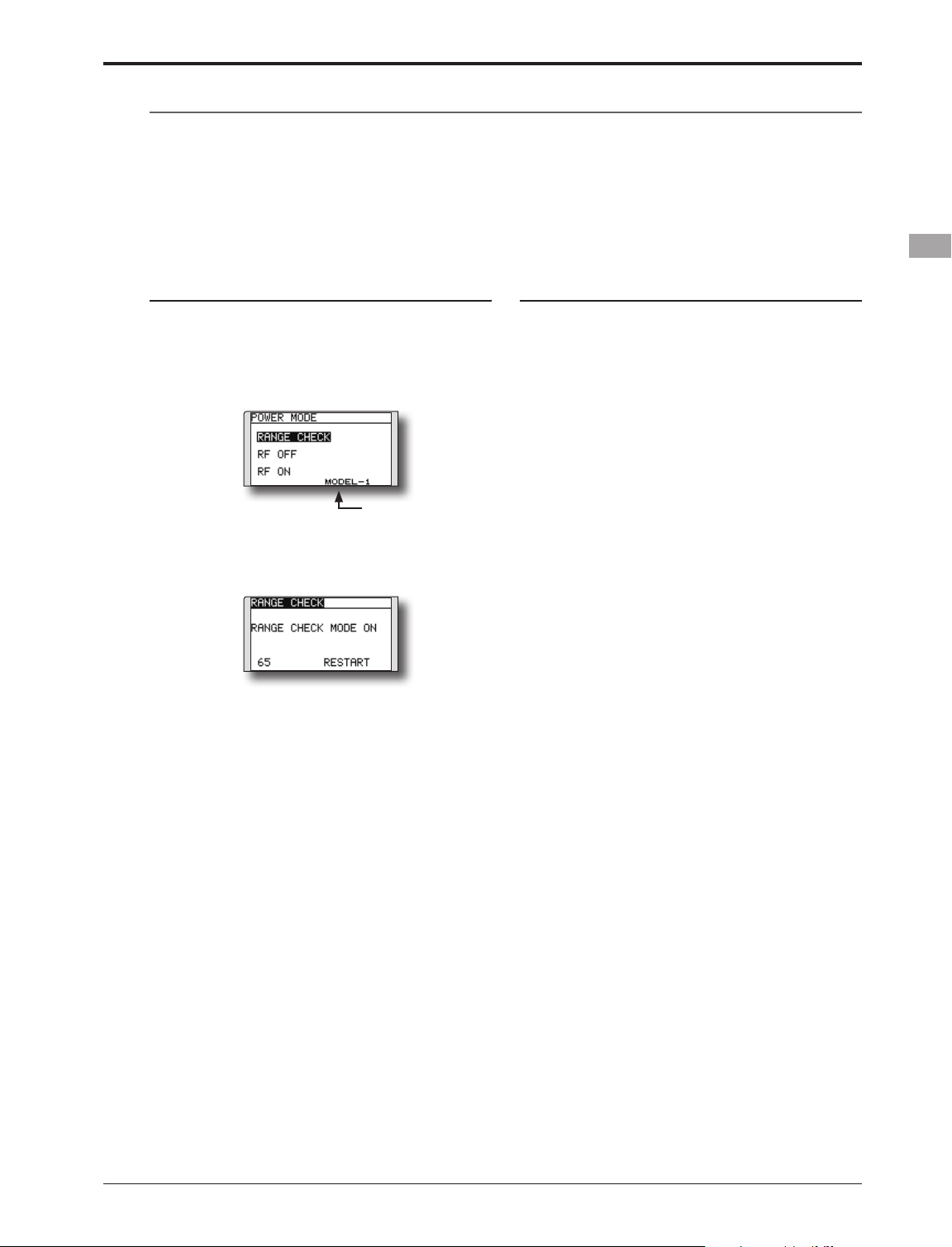
Range check mode
We have installed a special "Range check
mode" for doing a ground range check. To access
the "Range check mode" touch and hold the RTN
button while turning on the transmitter. Doing so
will bring up POWER MODE menu.
The present model
To activate the "Range check mode" touch the
RTN button and the range check mode screen will
appear.
During this mode, the RF power output is
reduced so the range test can be performed. In
addition, when this mode is activated the right
LED on the front of the transmitter starts blinking
and the transmitter gives users a warning with a
beeping sound every 3 seconds.
The "Range check mode" continues for 90
seconds and after that the power will return
to the normal level. To exit the "Range check
mode" before the 90 seconds, select the "RANGE
CHECK" at the top of the screen and touch the
RTN button again. This mode is available one
time only so if you need to re-use this function the
transmitter power must be cycled. NEVER start
ying when the "Range check mode" is active.
Should you require additional time to perform
a range check, highlight Restart before your time
expires and press the RTN button one time.
Range check procedure
1. With the "Range check mode" on, walk
away from the model while simultaneously
operating the controls. Have an assistant
stand by the model to confirm that all
controls are completely and correctly
operational. You should be able to walk
approximately 30-50 paces from the model
without losing control.
2. If everything operates correctly, return to
the model. Set the transmitter in a safe, yet
accessible, location so it will be within reach
after starting the engine or motor. Be certain
the throttle stick is in the low throttle position,
then start the engine or motor. Perform
another range check with your assistant
holding the aircraft with the engine running
at various speeds. If the servos jitter or move
inadvertently, there may be a problem. We
would strongly suggest you do not y until the
source of the difculty has been determined.
Look for loose servo connections or binding
pushrods. Also, be certain that the battery
has been fully charged.
<Basic Operation>
29
Page 30
RECEIVER AND SERVO INSTALLATION
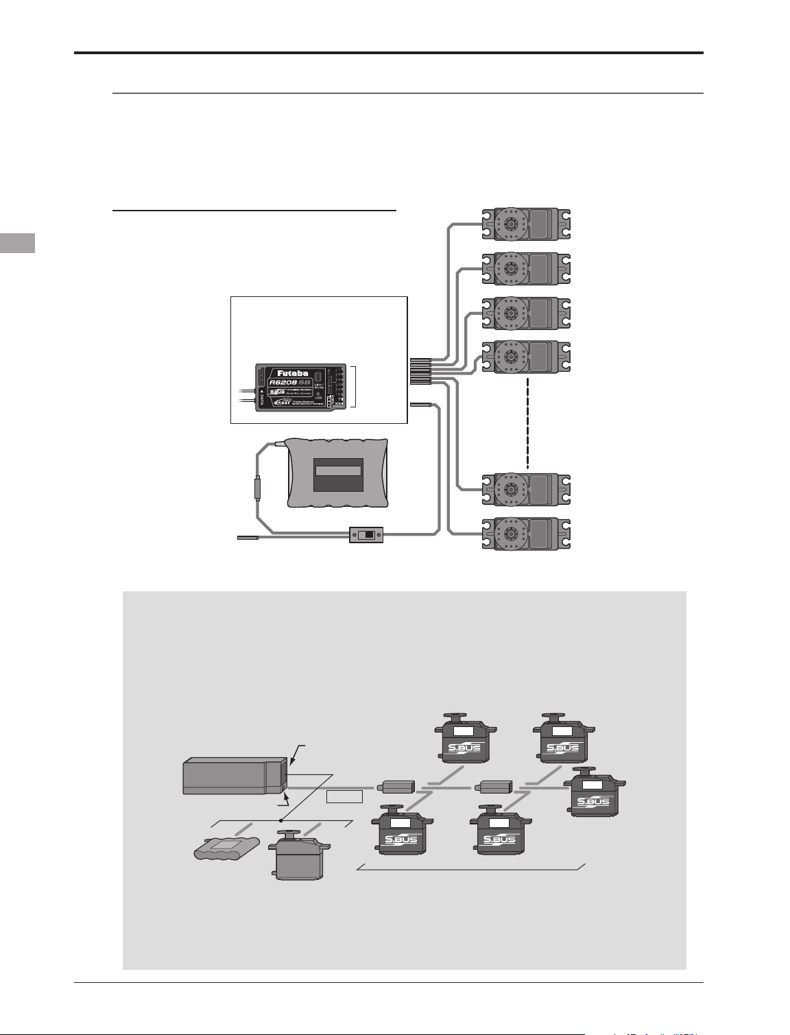
Receiver and servos connection
Connect the receiver and servos in accordance with the connection diagram shown below. Always read
[Precautions when mounting the receiver and servos] or [Before using]. When mounting the receiver and
servos to the fuselage, connect the necessary points in accordance with the model's instruction manual.
Receiver and servos connection diagram
Always connect the necessary number of servos.
The receiver channel assignment depends on the
model type. See the Servo connection by model
type tables.
R6208SB (output connector section)
•B: Power supply
•CH1~8: Output connectors 1~8
•S.BUS: Output for S.BUS system
•DATA port: (factory use only)
CH1~8,
S.BUS,
B
Receiver battery
Charging port
Receiver switch
Servos
• S.BUS system
Different from conventional radio control systems the S.BUS system uses data communication to
transmit control signals from a receiver to a servo, gyro, or other S.BUS compatible device. This data
includes commands such as “move the channel 3 servo to 15 degrees, move the channel 5 servo to
30 degrees” to multiple devices. The S.BUS devices execute only those commands for their own set
channel. For this reason, it can be used by connecting multiple servos to the same signal line.
[Connection by S.BUS system]
3ch 5ch
R6208SB
S.BUS output
Battery
Conventional
* Can also be used together with conventional servos.
* When using servos with a remote battery pack, use S.BUS Hub with Cable (2-way/remote battery pack use). Please refer
to the instruction manual of S.BUS Hub with Cable (2-way/remote battery pack use) for the connection method.
Ch output/
Battery terminal
servo
S.BUS hub S.BUS hub
S.BUS
2ch 4ch
6ch
S.BUS servo
<Receiver and Servo Installation>
30
Page 31

Servo connection by model type
The T8FGS transmitter channels are automatically assigned for optimal combination according to the
type selected with the Model Type function of the Linkage Menu. The channel assignment (initial setting)
for each model type is shown below. Connect the receiver and servos to match the type used.
*The set channels can be checked at the Function screen of the Linkage Menu. The channel assignments can also be changed. For
more information, read the description of the Function menu.
Airplane/glider
Normal wing and V-tail
(*1)
RX
CH
1 Aileron Aileron Aileron Aileron Aileron Aileron Aileron Aileron Aileron Aileron Aileron Aileron
2 Elevator Elevator Elevator Elevator Elevator Elevator Elevator Elevator Elevator Elevator Elevator Elevator
3 Throttle Motor Throttle Motor Throttle Motor Throttle Motor Rudder Rudder Rudder Rudder
4 Rudder Rudder Rudder Rudder Rudder Rudder Rudder Rudder Aileron2 Aileron2 Aileron2 Aileron2
5 Gear AUX7 Gear AUX7 Gear AUX6 Gear AUX5 Flap Flap Aileron3 Aileron3
6 VPP AUX6 Aileron2 Aileron2 Flap Flap Aileron2 Aileron2 Flap2 Flap2 Aileron4 Aileron4
7 AUX5 AUX5 VPP AUX6 Aileron2 Aileron2 Flap Flap Flap3 Flap3 Flap Flap
8 AUX4 AUX4 AUX5 AUX5 VPP AUX5 Flap2 Flap2 Flap4 Flap4 Flap2 Flap2
9/VC1 AUX1 AUX1 Camber Camber Camber Camber Camber Camber Camber Camber Camber Camber
1AIL
Airplane Glider Airplane Glider Airplane Glider Airplane Glider Airplane Glider Airplane Glider
2AIL
(*1)
2AIL+1FLAP
(*1)
2AIL+2FLAP
(*2)
2AIL+4FLAP
(*3)
4AIL+2FLAP
(*3)
10/VC2 AUX1 AUX1 AUX1 Buttery AUX1 Buttery VPP Buttery Gear Buttery Gear Buttery
11/VC3 AUX1 AUX1 AUX1 AUX1 AUX1 AUX1 AUX1 AUX1 Throttle Motor Throttle Motor
12/VC4 AUX1 AUX1 AUX1 AUX1 AUX1 AUX1 AUX1 AUX1 VPP AUX1 VPP AUX1
● The above table shows the channel allocation at the FASST MLT2 mode.
● The wing types which can be selected depend on the FASST MLT2/MULT or 7-ch, selected.
(*1)
These wing types are available on the MLT2, MULT and 7-ch mode. However, the ch8 doesn't work on the 7-ch mode.
(*2)
This wing type is available on the MLT2, MULT and 7-ch mode. However, since the ch8 doesn't work on the 7-ch mode, please
assign the ap2 to another channnel which isn't used.
(*3)
These wing types are available on the MLT2 and MULT mode only. (Except the airplane types on the MULT mode.)
<Receiver and Servo Installation>
31
Page 32

Ailvator (Dual Elevator)
(*1)
RX
CH
1 Aileron Aileron Aileron Aileron Aileron Aileron Aileron Aileron Aileron Aileron Aileron Aileron
2 Elevator Elevator Elevator Elevator Elevator Elevator Elevator Elevator Elevator Elevator Elevator Elevator
3 Throttle Motor Throttle Motor Throttle Motor Throttle Motor Rudder Rudder Rudder Rudder
4 Rudder Rudder Rudder Rudder Rudder Rudder Rudder Rudder Aileron2 Aileron2 Aileron2 Aileron2
5 Gear AUX7 Gear AUX7 Gear AUX6 Elevator2 Elevator2 Flap Flap Aileron3 Aileron3
6 VPP AUX6 Aileron2 Aileron2 Flap Flap Aileron2 Aileron2 Flap2 Flap2 Aileron4 Aileron4
7 Elevator2 Elevator2 Elevator2 Elevator2 Aileron2 Aileron2 Flap Flap Flap3 Flap3 Flap Flap
8 AUX4 AUX4 VPP AUX5 Elevator2 Elevator2 Flap2 Flap2 Flap4 Flap4 Flap2 Flap2
9/VC1 AUX1 AUX1 Camber Camber Camber Camber Camber Camber Camber Camber Camber Camber
10/VC2 AUX1 AUX1 AUX1 Buttery VPP Buttery Gear Buttery Gear Buttery Gear Buttery
11/VC3 AUX1 AUX1 AUX1 AUX1 AUX1 AUX1 VPP AUX1 Throttle Motor Throttle Motor
12/VC4 AUX1 AUX1 AUX1 AUX1 AUX1 AUX1 AUX1 AUX1 Elevator2 Elevator2 Elevator2 Elevator2
1AIL
Airplane Glider Airplane Glider Airplane Glider Airplane Glider Airplane Glider Airplane Glider
2AIL
(*1)
2AIL+1FLAP
(*2)
2AIL+2FLAP
(*3)
2AIL+4FLAP
(*4)
4AIL+2FLAP
● The above table shows the channel allocation at the FASST MLT2 mode.
● The wing types which can be selected depend on the FASST MLT2/MULT or 7-ch, selected.
(*1)
These wing types are available on the MLT2, MULT and 7-ch mode. However, the ch8 doesn't work on the 7-ch mode.
(*2)
This wing type is available on the MLT2, MULT and 7-ch mode. However, since the ch8 doesn't work on the 7-ch mode, please
assign the ap2 to another channnel which isn't used.
(*3)
These wing types are available on the MLT2 and MULT mode only. However, the glider type is available on the 7-ch mode,
please assign the ap2 to another channnel which isn't used.
(*4)
These wing types are available on the MLT2 mode only.
(*4)
<Receiver and Servo Installation>
32
Page 33

Flying wing, Delta wing (Winglet)
(*1)
RX
CH
1 Aileron Aileron Aileron Aileron Aileron Aileron Aileron Aileron Aileron Aileron
2 Rudder2 Rudder2 Rudder2 Rudder2 Rudder2 Rudder2 Aileron2 Aileron2 Aileron2 Aileron2
3 Throttle Motor Throttle Motor Throttle Motor Rudder Rudder Aileron3 Aileron3
4 Rudder Rudder Rudder Rudder Rudder Rudder Rudder2 Rudder2 Aileron4 Aileron4
5 Gear AUX7 Gear AUX6 Gear AUX6 Flap Flap Rudder Rudder
6 Aileron2 Aileron2 Flap Flap Flap Flap Flap2 Flap2 Rudder2 Rudder2
7 VPP AUX6 Aileron2 Aileron2 Aileron2 Aileron2 Flap3 Flap3 Flap Flap
8 AUX5 AUX5 VPP AUX5 Flap2 Flap2 Flap4 Flap4 Flap2 Flap2
9/VC1 Elevator Elevator Elevator Elevator Elevator Elevator Elevator Elevator Elevator Elevator
10/VC2 Camber Camber Camber Camber Camber Camber Camber Camber Camber Camber
11/VC3 AUX1 AUX1 AUX1 Buttery VPP Buttery Gear Buttery Gear Buttery
12/VC4 AUX1 AUX1 AUX1 AUX1 AUX1 AUX1 Throttle Motor Throttle Motor
2AIL
Airplane Glider Airplane Glider Airplane Glider Airplane Glider Airplane Glider
2AIL+1FLAP
(*1)
2AIL+2FLAP
(*2)
2AIL+4FLAP
(*3)
4AIL+2FLAP
(*3)
● The above table shows the channel allocation at the FASST MLT2 mode.
● The wing types which can be selected depend on the FASST MLT2/MULT or 7-ch, selected.
(*1)
These wing types are available on the MLT2, MULT and 7-ch mode. However, the ch8 doesn't work on the 7-ch mode.
(*2)
This wing type is available on the MLT2, MULT and 7-ch mode. However, since the ch8 doesn't work on the 7-ch mode, please
assign the ap2 to another channnel which isn't used.
(*3)
These wing types are available on the MLT2 and MULT mode only. (Except the airplane types on the MULT mode.)
<Receiver and Servo Installation>
33
Page 34

Helicopter
RX CH H-4, H4X Swash All Other
1 Aileron Aileron
2 Elevator Elevator
3 Throttle Throttle
4 Rudder Rudder
5 Gyro Gyro
6 Pitch Pitch
7 Governor Governor
8 Elevator2 Needle
9/VC1 Gyro2 Gyro2
10/VC2 Gyro3 Gyro3
11/VC3 AUX1 AUX1
12/VC4 AUX1 AUX1
● Since the ch8 doesn't work on the 7-ch mode, please
assign the elevator2 (H-4, H4X) or the needle (all
other) to 7 channnel if the governor is not used.
<Receiver and Servo Installation>
34
Page 35

Precautions when mounting the receiver and servos
Follow these guidelines to properly mount the servos, receiver and battery.
• Make certain the alignment tab on the battery,
switch and servo connectors is oriented correctly
and “keys” into the corresponding notch in the
receiver or connectors before plugging them
in. When unplugging connectors, never pull on
the wires. Always pull on the plastic connector
instead.
• If your aileron servo (or others) are too far away
to plug into the receiver, use a servo extension
cord to extend the length of the servo lead.
Additional Futaba extension cords of varying
lengths are available from your hobby dealer.
Always use an extension of the proper length.
Avoid plugging multiple extensions together to
attain your desired length. If distance is greater
than 18” or multiple or high current draw servos
are being used, use Futaba Heavy-Duty servo
extensions.
• Always mount the servos with the supplied
rubber grommets. Do not over tighten the
screws. No part of the servo casing should contact
the mounting rails, servo tray or any other part
of the airplane/helicopter structure. Otherwise,
vibration will be transmitted to the servo causing
premature wear and/or servo failure.
Servo
Rubber
grommet
Servo
Rubber
grommet
• Note the small numbers (1, 2, 3, 4) molded into
each arm on the Futaba 4-arm servo arms. The
numbers indicate how many degrees each arm
is “off” from 90 degrees to correct for minute
manufacturing deviations from servo to servo.
on the servo.
• After the servos are installed, operate each servo
over its full travel and check that the pushrods and
servo arms do not bind or contact each other. Also
make sure the controls do not require excess force
to operate. If there is an objectionable buzzing
sound coming from a servo, there is probably too
much resistance in the control. Find and correct
the problem. Even if there is no servo damage,
excess battery drain will result.
• Use the mounting plate from the receiver
on/off switch as a template for the cutout and
screw holes. Mount the switch on the side of the
fuselage opposite the engine exhaust, and where
it won’t be inadvertently turned on or off during
handling or storage. Be certain the switch moves
without restriction and “snaps” from ON to OFF,
and that the cutout allows full motion of the
switch in both directions.
• When you install the switch harness to the
helicopter, please use the switch cover. Generally
sandwich the frame between the switch and switch
cover and securely tighten the screws. Different
models might require different installations. If so,
please follow the model's instruction manual.
• To prevent the servo lead wires from being
broken by vibration during ight, provide a slight
amount of slack or extra so that the wire sticks
out slightly and fasten it at suitable points. In
addition, periodically check the wire during daily
maintenance.
• To center the servos, connect them to the receiver
and turn on the transmitter and receiver. Center
the trims on the transmitter, then nd the arm that
will be perpendicular to the pushrod when placed
Margin in the lead wire.
Fasten about 5-10cm
from the servo outlet so
that the lead wire is neat.
<Receiver and Servo Installation>
35
Page 36

Receiver's Antenna Installation
You will note that the R6208SB differs in appearance from the standard Futaba receiver. This receiver
incorporate two separate antennas into their design which enables them to receive the radio frequency
transmission at two different locations.
*Must be kept as straight as possible.
Antenna
Coaxial cable
R6208SB Receiver
Futaba's dual antenna diversity then seamlessly selects the best signal reception between these antennas
to ensure that there is no loss of signal.
To obtain the best results of the diversity
function, please refer to the following instructions:
1. The two antennas must be kept as straight as
possible. Otherwise it will reduce the effective
range.
2. The two antennas should be placed at 90
degrees to each other.
Antenna
This is not a critical figure, but the most
important thing is to keep the antennas
away from each other as much as possible.
Larger models can have large metal objects
that can attenuate the RF signal. In this case
the antennas should be placed at both
sides of the model. Then the best RF signal
condition is obtained at any ying attitude.
3. The antennas must be kept away from
conductive materials, such as metal, carbon
and fuel tank by at least a half inch. The
coaxial part of the antennas does not need
to follow these guidelines, but do not bend it
in a tight radius.
4. Keep the antennas away from the motor,
ESC, and other noise sources as much as
possible.
Antenna
*The two antennas should be placed at 90 degrees to each other.
*The main purpose of the photo demonstrates how the antenna should be placed.
*Receiver Vibration and Waterproong: The receiver contains precision electronic parts. Be sure to avoid vibration,
shock, and temperature extremes. For protection, wrap the receiver in foam rubber or other vibration-absorbing
materials. It is also a good idea to waterproof the receiver by placing it in a plastic bag and securing the open end of the
bag with a rubber band before wrapping it with foam rubber. If you accidentally get moisture or fuel inside the receiver,
you may experience intermittent operation or a crash. If in doubt, return the receiver to our service center for service.
<Receiver and Servo Installation>
36
Page 37

MODEL BASIC SETTING PROCEDURE
Airplane/glider basic setting procedure
1. Model addition and selection
Initially, the T8FGS assigns the first model to
model-01 in the transmitter. The Model Select
function of the Linkage Menu is used to add
models and to select amongst models which are
already set.
The T8FGS is capable of storing data for up
to 20 models in its internal memory. Additional
model data can also be saved to an optional SD
card.
The currently selected model name is displayed
in the center of the home screen. Before ying and
before changing any settings, always confirm the
model name.
When a new model is added, the Model type
select screen and FASST mode/Area select setup
screen automatically appear. Please be aware that
the transmitter will stop transmitting temporarily
when you change the model.
manual. For a description of the connection
method, see the Receiver and Servos Connection.
Note that even for the same "airplane
model", when the wing type and tail type
are different, the channel assignment may
be different. (The channel assigned to each
function can be checked at the Function
menu of the Linkage Menu.)
● If the direction of the servo is incorrect, adjust
the direction with the Reverse function of the
Linkage Menu.
● Adjust the neutral position and control
surface angle with the linkage, and fine
tune them with the Sub-Trim and End Point
functions (angle adjustment). To protect the
linkage, a limit position can also be set with
the End Point function. The End Point function
can adjust the amount of up/down and left/
right movement and limit of each channel.
2. Model type selection
Select the model type matched to the aircraft
with the Model Type select function of the Linkage
Menu. For an airplane, select the model type from
among the 2 types: airplane and glider. And then
select the wing type and the tail type matched to
the aircraft.
3. Fuselage linkage
Connect the ailerons, elevators, throttle, rudder,
etc. in accordance with the model's instruction
4. Throttle cut setting (Airplane)
Throttle cut can be performed with one touch by a
switch without changing the throttle trim position.
Set throttle cut with the Throttle Cut function of
the Linkage Menu. After activating the throttle cut
function and selecting the switch, adjust the throttle
position so that the carburetor becomes fully closed.
For safety, the throttle cut function operates the
throttle stick in the 1/3 or less (slow side) position.
<Model Basic Setting Procedure>
37
Page 38

5. Idle down setting (Airplane)
The idling speed can be lowered with one touch
by a switch without changing the throttle trim
position. Perform this setting with the Idle Down
function of the Linkage Menu. After activating the
Idle Down function and selecting the switch, adjust
the idle down speed. For safety, the idle down
function acts only when the throttle stick is in the
lowest part of its throw.
*While the Throttle Cut function is in operation, the Idle
Down function does not work.
6. D/R function
D/R function is used to adjust the throw and
operation curve of the stick functions (aileron,
elevator, rudder and throttle) for each switch
position (airplane) or each ight condition (glider).
This is normally used after the modeler has dened
the maximum throw directions in the End Point
settings.
(Airplane)
speed of the aileron, elevator, and ap servos can
be adjusted. You can also set the Auto Mode, which
will link Airbrake to a stick, switch, or dial. A
separate stick switch or dial can also be set as the
ON/OFF switch.
8. Addition of ight conditions (Glider)
The Condition Select function automatically
allocates the normal condition (NORMAL) for
each model. NORMAL is the default condition and
is the only one active when a new model type is
dened.
If you want to add ight conditions, please refer
to a description of the CONDITION function, p.80.
*The NORMAL is always on, and remains on until other
conditions are activated by switches, stick positions, etc.
Please refer to the section entitled Switch Selection Method
for additional information on how to do so.
*It is possible to customize the activation of the flight
conditions.
*The Condition Delay can be programmed for each channel.
The Condition Delay is used to change the servo throw
smoothly when switching conditions.
(Glider)
7. Airbrake (Airplane)
This function is used when an airbrake is
necessary when taking off or diving, etc. Please
note: this menu item is only available under certain
wing congurations. For example, it will not appear
if a single aileron wing type has been selected.
The pre-set elevator and ap offset amount can
be activated by a switch.
The offset amount of the aileron, elevator, and
flap servos can be adjusted as needed. Also the
<Model Basic Setting Procedure>
38
Page 39

Helicopter basic setting procedure
This section outlines examples of use of the helicopter functions of the T8FGS. Adjust the actual values,
etc. to match the fuselage used.
1. Model addition and selection
Initially, the T8FGS assigns the first model to
model-01 in the transmitter. To add new models
or to select a model already programmed, use the
Model Select function of the Linkage Menu.
This is convenient when selecting a model
after entering the model's names in advance. The
T8FGS is capable of storing up to 20 models in the
transmitter's internal memory. Additional models
can also be stored in an optional SD card.
The currently selected model is displayed in
the middle of the screen. Before flying and before
changing any settings, always confirm the model
name.
When a new model is added, the Model Type select
screen and Frequency setup screen automatically
appear. Change, or check that they match the swash
type and receiver type of the model used.
3. Flight condition addition
The transmitter offers up to ve ight conditions
per model.
The Condition Select function automatically
allocates ve conditions for helicopters.
(Initial setting)
● NORMAL
● IDLE UP1 (SW-E)
● IDLE UP2 (SW-E)
● IDLE UP3 (SW-F)
●HOLD (Hold switch is not assigned initially)
Note: Since you may accidentally activate
a condition that not previously setup during
ight which could cause a crash, we suggest
deleting conditions that are not used.
*For a description of the condition deletion, refer to the
Condition Select function, p.80.
The NORMAL condition is always on, and
remains on until other conditions are activated by
switches.
The priority is throttle hold/idle up 3/idle up
2/idle up 1/normal. Throttle hold has the highest
priority.
The Condition Delay can be programmed for
each channel and condition. The Condition Delay
is used to change the servo throw smoothly when
switching conditions.
2. Model type and swash type selection
If a different model type is already selected,
select helicopter with the Model Type function of
the Linkage Menu, and then select the swash type
matched to the helicopter.
*The Model Type function automatically selects the
appropriate output channels, control functions, and mixing
functions for the chosen model type. Six swash types are
available for helicopters.
*For a description of the swash type selection, refer to the
MODEL TYPE function, p.61-62.
(General ight condition setting example)
● Normal: (Use initial setting conditions/operate
when switch OFF)
Use from engine starting to hovering.
● Idle up 1: (Operate at SW-E center)
Use in 540º stall turn, loop, rolling stall turn, and other
maneuvers.
● Idle up 2: (Operate at SW-E forward side)
Use in rolls.
● Throttle hold: (Operate at SW-G forward side)
Use in auto rotation.
<Model Basic Setting Procedure>
39
Page 40

4. Servo Connection
Connect the throttle rudder, aileron, elevator,
pitch, and other servos in accordance with the
kit instruction manual. For a description of the
connection method, see "Receiver and Servos
Connection".
Note: The channel assigned to each function
can be checked at the Function menu of the
Linkage Menu.
● If the direction of operation of the servo
is incorrect, use the Reverse function of
the Linkage Menu. Also use the swash AFR
function in other than the H-1 mode.
5. Throttle/Pitch curve setting
This function adjusts the throttle or pitch
operation curve in relation to the movement of the
throttle stick for each condition.
<Throttle curve setting example>
Activate the throttle curve of each condition with
the condition select switch.
●Normal curve adjustment
Normal curve creates a basic throttle curve
centered near hovering. This curve is adjusted
together with the pitch curve (Normal) so that the
engine speed is constant and up/down control is
easiest.
●Idle up curve adjustment
The low side Throttle curve creates a curve
matched for aerobatics (loop, roll, 3D, etc.).
●Throttle hold curve adjustment
The curve is not used when performing auto rotation
dives.
Conrm that the rate of the slowest position (0%) of
the stick is 0% (initial setting).
● Adjust the direction of operation of the gyro.
(Gyro side function)
● Connect the throttle linkage so that the
carburetor can fully close at full trim throttle
cut.
● Adjust the neutral position at the linkage side
and ne tune with the Sub-Trim function and
End Point function. To protect the linkage,
a limit position can also be set with the End
Point function.
● Swash plate correction (Except H-1 mode)
*If any interactions are noticed, for a description of the
linkage correction function, please refer to the SWASH
function, p.73.
<Example of pitch curve setting>
Activate the pitch curve of each condition with
the condition select switch.
●Pitch curve (Normal)
Make the pitch at hovering approximately +5º~6º.
Set the pitch at hovering with the stick position at
the 50% point as the standard.
*Stability at hovering may be connected to the throttle curve.
Adjustment is easy by using the hovering throttle function
and hovering pitch function together.
●Pitch curve (Idle up 1)
The idle up 1 pitch curve function creates a curve
matched to airborne ight.
Set to -7º~+12º as standard.
●Pitch curve (Idle up 2)
The high side pitch setting is less than idle up 1.
The standard is +8º.
●Pitch curve (Hold)
At auto rotation, use the maximum pitch at both
the high and low sides.
[Pitch angle setting example]
Throttle hold: -7º~+12
º
<Model Basic Setting Procedure>
40
Page 41

6. D/R function
D/R function is used to adjust the throw and
operation curve of aileron, elevator and rudder for
each condition.
*For throttle and pitch curve settings, refer to the afore-
mentioned "Throttle/Pitch curve setting"
This is normally used after End Point has dened
the maximum throw directions.
7. Gyro sensitivity and mode switching
The gyro sensitivity and mode switching
function is utilized to adjust the gyro mixing of the
model, and can be set for each condition.
● Normal condition (hovering): Gyro sensitivity
maximum
● Idle up 1/Idle up 2/Throttle hold: Gyro
sensitivity minimum
● However, during auto rotations with a tail-
driven helicopter, this function may not have
any effect on the high gyro sensitivity.
8. Pitch to RUD mixing setting
Note: When using a GY601, GY502, GY520,
GY401, or other heading hold gyro, this
Pitch to RUD mixing should not be used. The
reaction torque is corrected by the gyro.
When operating the gyro in the AVCS mode,
the mixed signal will cause neutral deviation
symptoms and the gyro will not operate
normally.
for each condition. (At initial setting, this function
is in the "INH" state. To use it, set it to the "ON"
state.)
<Setting example>
Activate the mixing curve of each condition with
the condition select switch.
A curve setting example is shown below.
●Pitch to RUD mixing curve (Normal)
Use the hovering system and set this curve to
match take off and landing and vertical climb at a
constant speed.
●Pitch to RUD mixing (Idle up 1)
Use this curve in 540º stall turn, loop, and rolling stall
turn, and adjust it so the fuselage is facing straight
ahead when heading into the wind.
●Pitch to RUD mixing (Hold)
This function is set so that the fuselage is facing
straight ahead at straight line auto rotation. The
pitch of the tail rotor becomes nearly 0º.
9. Throttle hold setting
*If throttle hold is necessary, please refer to the THR HOLD
function, p.127.
10. Throttle cut setting
Throttle cut provides an easy way to stop the
engine, by ipping a switch with the throttle stick
at idle. The action is not functional at high throttle
to avoid accidental dead sticks. The switch’s
location and direction must be chosen, as it defaults
to NULL.
Use this function when you want to suppress
the torque generated by the changes in the pitch
and speed of the main rotor during pitch operation.
Adjust it so that the nose does not swing in the
rudder direction. However, when using a heading
hold gyro like those shown above, do not use Pitch
to rudder mixing.
Activate the Pitch to rudder (Pit -->RUD) mixing
function from the Model Menu, and set the curve
*With throttle stick at idle, adjust the cut position until the
engine consistently shuts off, but throttle linkage is not
binding.
11. Swash Mix corrects aileron, elevator and
pitch interaction
The swash mix function is used to correct the
swash plate in the aileron (Left/Right Cyclic)
and elevator (Forward/Aft Cyclic) direction
corresponding to each operation of each condition.
<Model Basic Setting Procedure>
41
Page 42

12. Throttle mixing setting
*If throttle mixing is necessary for a compensation for
slowing of engine speed caused by swash plate operation
during aileron or elevator operation, please refer to the
THROTTLE MIX function, p.129.
13. Other special mixings
●Pitch to Needle mixing
This mixing is used with engines with a design which
allows needle control during flight (fuel-air mixture
adjustment). A needle curve can be set.
●Governor mixing
This mixing is dedicated governor mixing when a
GV-1 (governor) is used.
<Model Basic Setting Procedure>
42
Page 43

TRAINER
DISPLAY
USER NAME
SOUND
H/W SET
START SEL.
AUTO LOCK
INFO
SYSTEM MENU
SYSTEM MENU
The System Menu sets up functions of the
transmitter: This does not set up any model data.
● Call the system menu shown below by
touching the SYS button twice at the home
screen, etc.
<SensorTouch™>
● Select [SYSTEM MENU]
and return to the home
screen by touching the
RTN button.
● Select the function you want to set and call
the setup screen by touching the RTN button.
Scrolling
● Moving cursor
●Access setup screen
System Menu functions table
[TRAINER]: Starts and sets the trainer system.
[DISPLAY]: LCD and back-light adjustment
[USER NAME]: User name registration
[SOUND]: Turns off the buzzer.
[H/W SET]: H/W reverse and stick mode
[START SEL.]: Immediately, a model selection can be performed
[AUTO LOCK]: The automatic lock function of two kinds of touch sensors
[INFO]: Displays the program version, SD card information, product ID, and language selection.
<Functions of System Menu>
43
Page 44

TRAINER
Trainer system starting and setting
The Trainer function makes it possible for the
instructor to choose which functions
(*1)
and channels
are to be used for instruction, making it possible to
match the training ability to the student's skill level.
Two transmitters must be connected by an optional
trainer cord, and the instructor's transmitter should
be programmed for trainer operation, as described
below.
When the Instructor activates the trainer switch,
the student has control of the aircraft (if MIX or
FUNC mode is turned on, the Instructor can make
corrections while the student has control). When
the switch is released the Instructor regains control.
This is very useful if the student gets the aircraft
into an undesirable situation.
You can select the channel input data from the
student transmitter as either "FUNC" or "MIX"
mode. These options make it easier to use a variety
of receivers, transmitters, etc.
It is also possible to use the virtual channel (VC)
at “FUNC” or “MIX” mode or to use the trainer
system with ying wing airplanes.
When using T8FGS as the student transmitter,
the trainer function is not used.
(*1)
You can select the operation mode for each channel.
(NORM/MIX/FUNC/OFF)
NOTE: This trainer system can be used in the
following manner;
1. With the T8FGS transmitter and a conventional
transmitter, if the channel order is different,
it is necessary to match the channel order
before using this function.
You can select the channel of input data
from student's transmitter in the "FUNC" or
"MIX" mode.
2. When the T8FGS is used as the instructor’s
transmitter, set the modulation mode of the
student’s transmitter to PPM.
If being used as the student, T8FGS can be
connected to the instructor's transmitter which
the PPM mode as the student's modulation
mode is required. T8FGS always sends PPM
mode signal from the trainer jack.
3. Be sure that all channels work correctly in
both transmitters before ying.
T8FGS/T8FG/T12FG special trainer cable
Use the T8FGS/T8FG/T12FG special trainer cable (FUTM4405) when using the T8FGS,
T8FG or T12FG transmitter at the trainer function instructor side. Operation may not be
normal with a conventional trainer cable.
*If the T8FGS, T8FG or T12FG transmitter is used as the student transmitter when the instructor transmitter is
not a T8FGS, T8FG or T12FG, a conventional trainer cable may be used.
Instructor Student Trainer cable
T4EX, T6EX, T7C, T9C, T10C T12FG special trainer cable
T8FGS, T8FG,
T12FG, FX-20
Other than
T8FGS, T8FG,
T12FG, FX-20
T8FGS, T8FG, T12FG, T12Z,
T14MZ, FX-40, FX-20
T4V Conventional trainer cable (Rect. - Round)
T6X, T7U, T8U, and T9Z are not applicable.
T8FGS, T8FG, T12FG, FX-20
Conventional trainer cable (Rect. - Rect.)
Conventional trainer cable (Rect. - Rect.) or
Conventional trainer cable (Rect. - Round)
*The direction that the T8FGS/T8FG/T12FG special trainer cable connects is fixed.
Connect the instructor cable adapter connector of the cable to the instructor T8FGS, T8FG or
T12FG and connect the student connector to the student transmitter. If the cable is connected
in reverse, the student's transmitter power will not be turned on even if the instructor side
power is set to ON.
*If the instructor side T8FGS, T8FG or T12FG trainer function is not enabled, the
student's power will not be turned ON even if the connection direction is correct.
<Functions of System Menu>
44
Page 45

● Select [TRAINER] in the System menu and enter the
setup screen shown below by touching the RTN
button.
● Select the function name
and return to the System
menu by touching the
RTN button.
Mode and switch selection
1. Access the setup screen page 4 shown
below by touching the S1 button three times.
2. Move the cursor to the [ACT] or [12/8CH]
item and touch the RTN button to switch to
the data input mode.
3. Select the mode by scrolling the touch
sensor. The display blinks. Touch the RTN
button to change the mode. (To terminate
the mode change, touch the S1 button.)
"ACT": Enable operation by changing to [OFF]
or [ON].
"12/8 CH": When the student uses the
T8FGS(MLT2 mode), T14MZ, T12Z, T12FG or FX40, select [12CH]. Otherwise select [8CH].
If changing the trainer switch:
4. Move the cursor to the [SW] item and touch
the RTN button to access the switch setup
screen.
(See "Switch selection method" at the end of
this manual for selection method details.)
"SW": Select the desired switch.
Initial setting: SH
*The switch mode can also be selected when setting the ON
position on the switch setup screen. When [ALTERNATE
OFF] is selected, normal ON/OFF operation is performed.
When [ALTERNATE ON] is selected, the trainer function
is alternately turned on and off each time the switch is
operated. This allows alternate ON/OFF switching even
when a momentary switch (SH) is used.
<SensorTouch™>
Scrolling
● Moving cursor
● Selecting mode
● Adjusting value
● To next page
Note: The trainer function won’t be turned
on unless the Instructor's transmitter receives
signals from the student's transmitter. Be
sure to confirm this after connecting your
trainer cable.
Operating mode selection
(Setup screen page 1-3)
1. Move the cursor to the [MODE] item of the
channel you want to change and touch the
RTN button to switch to the data input mode.
2. Select the mode by scrolling the touch
sensor. The display blinks. Touch the RTN
button to change the mode. (To terminate
the mode change, touch the S1 button.)
"MODE": Select the desired operation mode
for each channel.
NORM: The model is controlled by signals from the student
transmitter.
MIX mode: The model is controlled by signals from the
instructor and student transmitters. (Reset the student's
model data to the default condition.)
FUNC mode (function mode): The model is controlled by
signals from the student transmitter with the instructor 's
setting. (Reset the student's model data to the default
condition.)
OFF: Only the instructor side operates.
Adjusting the student's rate.
*The setting above allows setting of the servo throw relative
to the amount of student side operation when [MIX] or
[FUNC] was selected.
<Functions of System Menu>
45
Page 46

1. Move the cursor to the [RATE] item of the
channel you want to change and touch the
RTN button to switch to the data input mode.
2. Adjust the rate by scrolling the touch sensor.
"RATE": Adjust the desired rate.
Setting range: 0~100%
Initial value: 100%
*When you want to reset the value to the initial state, touch
the RTN button for one second.
3. To end adjustment, touch the RTN button
and return to the cursor mode.
Changing the student's channel
*The setting above allows setting of the channel assignment
of student side when [MIX] or [FUNC] was selected.
1. Move the cursor to the [STU. CH] item of the
channel you want to change and touch the
RTN button to switch to the data input mode.
2. Select the channel by scrolling the touch
sensor. The display blinks. Touch the RTN
button to change the channel. (To terminate
the mode change, touch the S1 button.)
"STU. CH": Match the channel order of the
Instructor's and student's transmitter.
<Functions of System Menu>
46
Page 47

DISPLAY
LCD contrast, back-light brightness and back-
light off-timer adjustment are possible:
● Select [DISPLAY] at the system menu and access
the setup screen shown below by touching the
RTN button.
LCD and back-light adjustment
● Select the function name
and return to the System
menu by touching the
RTN button.
LCD contrast adjustment
1. Select "CONTRAST" and touch the RTN button
to switch to the data input mode and adjust
the contrast by scrolling the touch sensor.
"CONTRAST": Adjust the contrast to the
desired value while watching the screen
display.
Setting range: (Lighter) 0 to 15 (Darker)
Initial value: 5
*When you want to reset the value to the initial state, touch
the RTN button for one second.
2. Touch the RTN button to end adjustment and
return to the cursor mode.
Back-light brightness adjustment
1. Select "BRIGHTNESS" and touch the RTN
button to switch to the data input mode and
adjust the back-light brightness by scrolling
the touch sensor.
"BRIGHTNESS": Adjust the brightness to the
desired value while watching the screen
display.
Setting range: OFF, 1 to 20(Lighter)
Initial value: 10
<SensorTouch™>
Scrolling
● Moving cursor
● Adjusting value
*When you want to reset the value to the initial state, touch
the RTN button for one second.
2. Touch the RTN button to end adjustment and
return to the cursor mode.
Back-light off-timer
1. Select "OFF TIMER" and touch the RTN button
to switch to the data input mode and adjust
the back-light off-timer by scrolling the touch
sensor.
"OFF TIMER": Adjust the time when the back-
light turns off after operating the touch
sensor.
Setting range: 10 to 240 sec (each 10 sec),
OFF (always on)
Initial value: 10 sec
*When you want to reset the value to the initial state, touch
the RTN button for one second.
2. Touch the RTN button to end adjustment and
return to the cursor mode.
<Functions of System Menu>
47
Page 48

USER NAME
This function allows the modelers to change the
T8FGS user name.
*A name of up to 10 characters can be entered as the user
name. Please note that a space is also counted as one
character.
● Select [USER NAME] at the System menu and
access the setup screen shown below by touching
the RTN button.
User name registration
User name (candidate)
● Select the function name
and return to the System
menu by touching the
RTN button.
User name registration
1. Change the user name as described below:
[Moving cursor in user name (candidate)]
Select [←] or [→], and touch the RTN button.
[Deleting a character]
When [DELETE] is selected and the RTN button
is touched, the character immediately after
the cursor is deleted.
[Adding a character]
When a character is selected from the
character list and the RTN button is touched,
that character is added at the position
immediately after the cursor.
*A name of up to 10 characters long can be entered as the
user name. (A space is also counted as 1 character.)
<SensorTouch™>
Scrolling
● Moving cursor
(Character list 1/3)
(Character list 2/3)
(Character list 3/3)
2. Upon completing the input, select [ENTER]
and touch the RTN button. (To terminate
input and return to the original state, select
[CANCEL] and touch the RTN button.)
<Functions of System Menu>
48
Page 49

SOUND
The warning sound and other sound of the
T8FGS transmitter can be turned off.
*When “WARNING” was set to OFF, the no operation alarm
(30 minutes), mixing warning sound, and low battery alarm
sounds are turned OFF.
● Select [SOUND] at the system menu and access
the setup screen shown below by touching the
RTN button.
Turns off the buzzer.
● Select the function name
and return to the System
menu by touching the
RTN button.
On/off operation
1. Move the cursor to the [TIMER][WARNING]
or [OTHER SOUND] item and touch the RTN
button to switch to the data input mode.
2. Select the ON or OFF by scrolling the touch
sensor.
*The display blinks.
3.Touch the RTN button.
Low Battery Alarm
The T8FGS includes an audible alarm that sounds
when the transmitter’s battery voltage drops below
a pre-determined setting; adjustable for cell types
and voltages.
<SensorTouch™>
Scrolling
● Moving cursor
● Selecting mode
Accessing and Activating the Low Battery
Alarm
1. The Low Battery (LOW BATTERY) alarm
voltage is accessed through the T8FG’s
System Menu. Within the System Menu, use
the SensorTouch™ to highlight the SOUND
option and then press the Return (RTN)
button to conrm the selection.
2. Use the SensorTouch to scroll to the Low
Battery (LOW BATTERY) alarm, and then press
the Return (RTN) button to access the voltage
settings. Using the SensorTouch, adjust the
voltage as desired and/or determined by
the transmitter battery pack being utilized.
The voltage options range from 6.0V to 7.4V.
Suggested voltage settings are as follows:
6-Cell NiCd or NiMH: 6.8V
2-Cell LiFe: 6.0-6.2V
2-Cell LiPo: 7.2-7.4V
<Functions of System Menu>
49
Page 50

H/W SETTING
Hardware reverse and stick mode
H/W reverse
This function reverses the operation direction of
the sticks, switches, trimmer levers, and knobs.
Note: This setting reverses the actual operation
signal, but does not change the display
indicators. Use the Normal mode as long as
there is no special reason to use the Reverse
mode.
Stick mode
This function changes the stick mode of
transmitter.
● Select [H/W SET] at the system menu and access
the setup screen shown below by touching the
RTN button.
● Select the function name
and return to the System
menu by touching the
RTN button.
Note: This will not change the throttle ratchet,
etc. Those are mechanical changes that
must be performed by a Futaba service
center.
Note: After changing the mode, these changes
are only applied to new models. It is not
applied to an existing model.
Stick calibration
J1-J4 stick correction can be performed.
<SensorTouch™>
Scrolling
● Moving cursor
●Access setup screen
Operation direction reversal method
1. Select [H/W REVERSE] and access the setup
screen shown below by touching the RTN
button.
2. Move the cursor to the item corresponding
to the H/W (hardware) you want to reverse
and touch the RTN button to switch to the
data input mode.
3. Select the mode by scrolling the touch
sensor. The display blinks. When the RTN
button is touched, the operation direction is
reversed. (To terminate the mode change,
touch the S1 button.)
"NORM": Normal operation direction
"REV" : Operation direction is reversed.
Changing stick mode
1.Select [STICK MODE] and access the setup
screen shown below by touching the RTN
button.
2. Move the cursor to the "STICK MODE" item
and touch the RTN button to switch to the
data input mode.
3. Select the mode. The display blinks. When
the RTN button is touched, the stick mode is
changed. (To terminate the mode change,
touch the S1 button.)
(J3)
(J4)
Mode J1 J2 J3 J4
1 Aileron Throttle Elevator Rudder
2 Aileron Elevator Throttle Rudder
3 Rudder Throttle Elevator Aileron
4 Rudder Elevator Throttle Aileron
(J2)
(J1)
<Functions of System Menu>
50
Page 51

Stick calibration method
*J3 and J4 correction is described below. J3 and J4 correction
is performed using the same procedure.
1.Select [CALIBRATION] and access the setup
screen shown below by touching the RTN
button.
2.Move the cursor to the J3-J4 button and
touch the RTN button.
3.Move the J3 or J4 sticks to the neutral position
and press the RTN button for one second.
4.Set the J3 and J4 sticks fully to the bottom
right and wait until the buzzer sounds.
5.Set the J3 and J4 sticks fully to the top left and
wait until the buzzer sounds.
6.The above completes the correction
operation. Operate and check if stick
correction was performed normally.
<Functions of System Menu>
51
Page 52

MODE
OFF
START SEL.
START SEL.
Immediately, a model selection can be performed
START SEL is a function which starts and can
perform a model selection immediately.
Each time, it is convenient for the modeler
which is enjoying two or more models by one of a
transmitter.
Quick Select Screen
As the name suggests, the Quick Model Select
Function enables the modeler to change the
selected models rapidly each time the transmitter is
● Select the function name
and return to the System
menu by touching the
RTN button.
START SEL.
MODE
OFF
Setting Up and Adjusting the Quick Select Models
1. The Start Selection (START SEL.) menu is
accessed through the T8FG’s System Menu.
Turn the transmitter ON and then press the
SYS (System) button two times. Use the
SensorTouch™ to highlight the Start Selection
(START SEL.) and then press the Return (RTN)
button to conrm the selection.
2.The Start Selection (START SEL.) menu option
defaults to OFF meaning that Quick Select
and Model Select are not applicable. To
activate the Quick Select or Model Select,
use the SensorTouch to scroll to the OFF
setting as denoted in the image. With the
OFF indication highlighted, press the Return
(RTN) button and rotate the SensorTouch once
again to scroll amongst the options. With the
Quick Select (QUICK SEL.) indicated, press the
Return (RTN) button once again to make the
desired selection as indicated.
Quick Select Activation:
With the Quick Select (QUICK SEL.) option
activated, there are two additional options available
for customization; ALWAYS and MDL (Model).
These options determine if/when the Quick Select
<Functions of System Menu>
52
turned ON. With a few quick touches, it is possible
to change models whereas before it would require
a multi-step process. The T8FGS stores up to four
models in the Quick Select offerings.
Model Select Screen
The transmitter is turned on, it will move to the
screen of a model selection immediately
<SensorTouch™>
information will appear on-screen. ALWAYS,
as the name suggests, indicates that each time
the transmitter is powered-up, the Quick Select
information will appear on-screen. The MDL
(Model) setting indicates that the Quick Select
information will appear on-screen only when
the MDL button is pressed simultaneously as the
transmitter is turned ON. With the Quick Select
mode highlighted, use the SensorTouch to move to
the activation setting options. Model (MDL) is the
default setting. Press the Return (RTN) button to
bring forth the options, then scroll to the ALWAYS
setting using the SensorTouch pad. Press the Return
(RTN) button once again to nalize the selection.
Assigning models to the sensor buttons:
There are four sensors/buttons that correspond
with the SensorTouch: Link (LNK), Model (MDL)
System (SYS) and S1. As such, it is possible to offer
up to four models available through the Quick Select
function. We suggest using the models that you y
most often.
1. Use the SensorTouch, scroll to the desired
sensor/button for the rst model; for example,
Link (LNK).
Page 53

2. With the input next to the desired sensor
highlighted, press the Return (RTN) button one
time.
3. Using the SensorTouch, scroll through the
available models. To select the desired model,
press the Return (RTN) button.
4. Repeat as desired for the remaining sensors.
Using the sensors to select the model:
1. Turn ON the transmitter, activating the Quick
Select screen. If Model (MDL) has been
selected, please be sure to press the Model
(MDL) sensor when powering up the transmitter.
* Please note: Even if the Quick Select function is active, the
Power Mode screen will appear when the transmitter is turned
ON while simultaneously pressing the Return (RTN) button.
2. To select the model assigned to a particular
sensor, double-click the desired sensor. For
example, MODEL- 03 is assigned to S1, doubleclick S1 to bring forth all settings, etc. for Model
-03. The T8FGS offers an audible and visual
confirmation as the selected model memory is
changed accordingly.
* If the Return (RTN) button is double-clicked, the T8FGS the
current model is selected as indicated on the display. That is,
the model that was used prior to the last time the transmitter
was turned OFF.
Model Select Screen
This update also allows the Model Select screen to be
accessed immediately upon turning ON the transmitter.
* Please note: this function cannot be utilized at the same time as
the Quick Select function. If more than four models are own
regularly, we suggest that the Model Select function be utilized
as it will save time when selecting the desired aircraft. If four,
or fewer, models are own, the Quick Select option would be the
best choice.
* Please note: the Model Select function does not allow access
to the RENAME, COPY or DELETE options. To utilize one
of these options, please access the Model Select screen in the
typical manner as described in the complete instruction manual.
1.The Start Selection (START SEL.) menu is accessed
through the T8FG’s System Menu. Turn the
transmitter ON and then press the SYS (System)
button two times. Use the SensorTouch™ to
highlight the Start Selection (START SEL.) and
then press the Return (RTN) button to conrm the
selection.
2. The Start Selection (START SEL.) menu option
defaults to OFF meaning that Quick Select
and Model Select are not applicable. To
activate the Quick Select or Model Select, use
the SensorTouch to scroll to the OFF setting as
denoted in the image. With the OFF indication
highlighted, press the Return (RTN) button and
rotate the SensorTouch once again to scroll to
the Model Select (MODEL SEL.). Press the Return
(RTN) button once again to activate Model
Select as indicated.
Model Select Activation:
With the Model Select (MODEL SEL.) option
activated, there are two additional options available
for customization; ALWAYS and MDL (Model).
These options determine if/when the Model Select
information will appear on-screen. ALWAYS, as the
name suggests, indicates that each time the transmitter
is powered-up, the Model Select information will
appear on-screen. The MDL (Model) setting indicates
that the Model Select information will appear onscreen only when the MDL button is pressed
simultaneously as the transmitter is turned ON.
With the Model Select mode highlighted, use the
SensorTouch to move to the activation setting options.
Model (MDL) is the default setting. Press the Return
(RTN) button to bring forth the options, then scroll
to the ALWAYS setting using the SensorTouch pad.
Press the Return (RTN) button once again to nalize
the selection.
Using the Model Select Function:
<Functions of System Menu>
53
Page 54

1. Turn ON the transmitter, activating the Model
Select screen. If Model (MDL) has been
selected, please be sure to press the Model
(MDL) sensor when powering up the transmitter.
*Please note: Even if the Model Select function is active, the
Power Mode screen will appear when the transmitter is turned
ON while simultaneously pressing the Return (RTN) button.
2. The SensorTouch is used to select amongst the
on-screen models. The most recently used
model memory will automatically highlighted
when the transmitter is turned ON. To select
this memory, press the Return (RTN) button. If a
different model is desired, use the SensorTouch
to scroll through the available options; each
highlighted accordingly. Again, to select
a model, press the Return (RTN) button
accordingly. The T8FGS offers an audible and
visual confirmation as the selected model
memory is changed.
<Functions of System Menu>
54
Page 55

LOCK TIMER
OFF
START LOCK
OFF
AUTO LOCK
AUTO LOCK
The automatic lock function of two kinds of SensorTouch
The Auto Lock function makes it possible to
automatically lock the transmitter to prevent any
unwanted programming/input when in use.
The auto lock function can be set in two ways.
LOCK TIMER
Auto Lock functions automatically when there is
no operation from the HOME screen display for a
chosen number of seconds.
AUTO LOCK
● Select the function name
and return to the System
menu by touching the
RTN button.
Auto lock method
1. Open the Auto lock screen in the system
menu.
LOCK TIMER
START LOCK
START LOCK
Auto Lock functions automatically when the
model changes or power is turned on.
*To temporarily allow access to the T8FG/S' programming
press and hold the S1 key for one second. Please note, the
Auto Lock function timer will resume immediately once
again.
● Manual lock
If S1 button is touched 1 second
or more from a HOME screen, a
SensorTouch locks manually.
<SensorTouch™>
OFF
OFF
● Lock release
Every lock function's touch [ 1 second
or more ] of S1 button will release a
lock.
2. Adjust the activation timer for the Auto
Lock function. The timer will begin counting
immediately when the HOME screen is not
used. The timer is adjustable in one second
increments up to 30 seconds. If the timer
value is OFF, this function is not applicable.
AUTO LOCK
LOCK TIMER SEC
START LOCK
5
OFF
3.The Start Lock setting will, if enabled,
automatically lock the T8FG/S when the
transmitter is powered up. To allow access to
the transmitter's functions, press and hold the
S1 key for one second.
AUTO LOCK
LOCK TIMER SEC
START LOCK
*If neither the Lock Timer or Start Lock functions are active
(OFF), then the key lock remains even if the power is turned
off.
*If the Lock Timer is enabled and the Start Lock is off, the key
lock status if canceled each time the T8FG/S is turned on.
5
ON
● Display of a lock
If locked, there will be sound and the
icon of a key will come out.
Danger
The Lock a SensorTouch during a
ight. If a SensorTouch is touched on
accidentally, a setup will change and
control will become impossible.
<Functions of System Menu>
55
Page 56

INFO
Displays the program version, SD card information, and product ID.
The T8FGS system program version information,
SD card information (current and maximum
number of model data and other les), and product
ID are displayed on the Information screen.
*When the SD card is not inserted, the SD card information is
not displayed.
● Select [INFO] at the system menu and access the
setup screen shown below by touching the RTN
button.
● Select the function name
and return to the System
menu by touching the
RTN button.
The language displayed in home, menu, and
setup screen is selectable.
<SensorTouch™>
Scrolling
● Moving cursor
● Selecting mode
Information
"PRODUCT": Product ID number
"VERSION": T8FGS system program version
information
"CARD SIZE": Current/Maximum number of
model data and other les (SD card)
Language selection
1. Move the cursor to the "LANGUAGE" item
and touch the RTN button to switch to the
data input mode.
2. Change the language by scrolling the touch
sensor. The display blinks. When the RTN
button is touched, the language is changed.
(To terminate the mode change, turn the
EDIT dial or push the S1 button.)
<Functions of System Menu>
56
Page 57

FUNCTIONS OF LINKAGE MENU
The Linkage Menu is made up of functions
which perform model addition, model type
selection, frequency setting, end point setting, and
other model basic settings.
● Access the Linkage menu shown below by
tapping the LNK button two times.
● Select [LINKAGE MENU]
and return to the home
screen by touching the
RTN button.
The functions which can be selected depend on
the model type. A typical menu screen is shown
below.
<SensorTouch™>
Scrolling
● Moving cursor
●Calling setup screen
*The display screen is an example. The
screen depends on the model type.
● Select the function you want to set and call
the setup screen by touching the RTN button.
Linkage Menu functions table
[SERVO]: Displays the servo test and operation position
[MODEL SEL]: Model addition, call, deletion, copy, model name setting
[MODEL TYPE]: Model type, wing type, swash type, etc. selection
[FREQUENCY]: FASST mode selection and area mode selection
[FUNCTION]: Channel assignment of each function can be changed
[SUB-TRIM]: Adjusts the neutral position of each servo
[REVERSE]: Reverses the servo travel direction
[FAIL SAFE]: Fail safe function and battery fail safe function setting
[END POINT]: Servo travel adjustment and limit setting
[THR CUT]: Stops the engine safely and easily (airplane and helicopter only)
[IDLE DOWN]: Lowers the idle speed of the engine (airplane only)
[SWASH RING]: Limits the swash plate travel to within a xed range. (helicopter only)
[SWASH]: Swash AFR and linkage correction function (helicopter only)
[T1-T4 SET.]: Control step amount and mode selection of the digital trim
[WARNING]: Mixing warning normal reset
[DATA RESET]: Model memory set data reset
<Functions of Linkage Menu>
57
Page 58

SERVO MONITOR
Servo Test & Graph Display / Displays servo positions.
This is used for testing servo movement.
“Moving Test” (repetition mode) and “Neutral
Test” (xed position mode) are available.
The “Neutral Test” is good for finding the
neutral position of a servo horn.
● Select [SERVO] in the Linkage menu and access
the setup screen shown below by touching the
RTN button.
● Select the function name
and return to the Linkage
menu by touching the
RTN button.
In order to prevent any potential difficulties,
the servo test function will be inoperable, or
inaccessible, under certain conditions. Specically,
the Servo Test function is not operational if the
Throttle Cut is ON in either airplane or helicopter
modes; or if the Throttle Hold is ON in Helicopter
mode.
<SensorTouch™>
Scrolling
● Moving cursor
● Selecting mode
Servo test operation
1. Move the cursor to the [OFF] item and touch
the RTN button to switch to the data input
mode.
Select the test mode by scrolling the touch
sensor and touch the RTN button. The display
blinks. Touch the RTN button to change the
mode. (To terminate mode change, touch
the S1 button.)
[MOVING]: Mode which repeats operation of
each servo
[NEUTRAL]: Mode which locks each servo in
the neutral position
2. Move the cursor to the [MOVING] or
[NEUTRAL] item and touch the RTN button to
switch to the data input mode.
Select the [OFF] by scrolling the touch sensor
and touch the RTN button. Testing is stopped.
<Functions of Linkage Menu>
58
Page 59

MODEL SELECT
The Model Selection function performs model addition, selection,
deletion, copy, and model name setting.
This function is used to load the settings of the
desired model into the T8FGS’s memory.
The settings may be selected from either the
transmitter’s internal memory or an SD card (32MB2GB). Remember that up to 20 model memories are
available in the transmitter.
The name of the model stored in the transmitter and
the SD card may be changed. This can be very useful
to tell different models settings apart. Each model name
can be as long as 10 characters, and the model name
● Select [MODEL SELECT] in the Linkage menu
and access the setup screen shown below by
touching the RTN button.
● Select the function name
and return to the Linkage
menu by touching the
RTN button.
always appears in the display screen.
The Copy function is used to copy parameters,
settings, etc. from one model data into a second
memory. It may be used for getting a head-start on
setting up models with almost the same settings (only
differences need to be modied, instead of entering the
complete model from scratch). Also, this function may
be used to make a backup copy of a model setup before
any changes are made.
Current model
<SensorTouch™>
Scrolling
● Moving cursor
● Selecting mode
(Model list)
Model selection
*Model data saved on the transmitter memory other than the
model currently used can be selected.
1. Move the cursor to the save destination
display ("TX" or "CARD") and touch the RTN
button to switch to the data input mode.
Select the save destination by scrolling the
touch sensor and touch the RTN button.
[TX]: Transmitter memory
[CARD]: SD card
2. After moving the cursor to the desired model
in the model list, touch the RTN button.
3. Move to [SELECT].
4.Touch the RTN button. A confirmation
message is displayed. Touch the RTN button
for one second and selection is complete.
*The display screen is an example. The
screen depends on the model type.
Model addition
*A new model can be added to the transmitter memory. It can
not be added to the SD card.
1. Move the cursor to [NEW].
2. Touch the RTN button. A confirmation
message appears. Touch the RTN button for
one second.
*The model type setup screen and frequency setup screen are
automatically displayed. Conrm or change the model type
and FASST mode.
*Transmission stops and then starts in the state of the new
model.
*The added model appears in the model list of the model
select setup screen.
*Transmission stops and then starts in the state of the new
model.
<Functions of Linkage Menu>
59
Page 60

Model deletion
*The model stored in the transmitter memory or an SD card
can be deleted.
*The current model can not be deleted.
1. Move the cursor to the save destination
display ("TX" or "CARD") and touch the RTN
button to switch to the data input mode.
Select the save destination by scrolling the
touch sensor and touch the RTN button.
[TX]: Transmitter memory
[CARD]: SD card
2. Move the cursor to the model you want to
delete in the model list and then touch the
RTN button.
3. Move the cursor to [DELETE].
4. Touch the RTN button. When a conrmation
message is displayed and the RTN button
is touched for one second, the model is
deleted.
Model name change
*The model name of the model stored in the transmitter
memory or a SD card can be changed.
1. If changing the location:
Move the cursor to the save destination
display ("TX" or "CARD") and touch the RTN
button to switch to the data input mode.
Select the save destination by scrolling the
touch sensor and touch the RTN button.
[TX]: Transmitter memory
[CARD]: SD card
2. Move the cursor to the model you want to
change in the model list and then touch the
RTN button.
3. Move to [RENAME].
4. Touch the RTN button.
*The model name setup screen is displayed.
User name (candidate)
4. Change the model name as described
below:
[Moving cursor in the user name (candidate)]
Select [←] or [→], and touch the RTN button.
[Deleting a character]
When [DELETE] is selected and the RTN button
is touched, the character immediately after
the cursor is deleted.
[Adding a character]
When a character is selected from the
character list and the RTN button is touched,
that character is added at the position
immediately after the cursor.
*A name of up to 10 characters long can be entered as the
model name. (A space is also counted as one character.)
5. After the desired information has been input,
select [ENTER] and touch the RTN button.
(To terminate input and return to the original
state, select [CANCEL] and touch the RTN
button.)
Model copy
*A copy can be made of the model stored in the transmitter
memory or an SD card.
1. If changing the location:
Move the cursor to the save destination
display ("TX" or "CARD") and touch the RTN
button to switch to the data input mode.
Select the save destination by scrolling the
touch sensor and touch the RTN button.
[TX]: Transmitter memory
[CARD]: SD card
2. Select the model you want to copy in the
model list and then touch the RTN button.
2. Move to [COPY].
3. Touch the RTN button.
*The copy screen appears.
4. If replacing the model stored in the
transmitter memory:
Move to [ADD-LIST] and touch the RTN button
to switch to the data input mode.
Select the destination model by scrolling the
touch sensor and touch the RTN button.
[ADD-LIST]: adding the model to the list
[(model name)]: replacing the model
*The model stored in the SD card can be replaced.
If changing the location:
Move the cursor to the copy destination
display ("TX" or "CARD") and touch the RTN
button to switch to the data input mode.
Select the save destination by scrolling the
touch sensor and touch the RTN button.
5. Move to [COPY].
6. Touch the RTN button. When a conrmation
message is displayed and the RTN button is
touched for one second, the model data is
copied.
<Functions of Linkage Menu>
60
Page 61

MODEL TYPE
This function selects the model type from among airplane, helicopter,
and glider.
Six swash types are available for helicopters.
Six types of main wings and three types of tail
wings are available for airplanes and gliders.
Functions and mixing functions necessary for each
model type are set in advance at the factory.
Note: The Model Type function automatically
selects the appropriate output channels,
control functions, and mixing functions for the
chosen model type.
When the Model Type selection command
is accessed, all of the data in the active
memory is cleared (except the following
swash type.) Be sure that you don’t mind
losing this data, or back it up to another
memory using the copying functions.
● Select [MODEL TYPE] in the Linkage menu and
access the setup screen shown below by touching
the RTN button.
● Select the function name
and return to the Linkage
menu by touching the
RTN button.
When changing the helicopter swash type
within the following groups, you can leave
the settings other than the SWASH function.
However, this is initialized when you change
the swash type to the other swash type
group.
Swash type group A:
H-1, H-3, HR3, and HE3
Swash type group B:
H-4, H-4X
<SensorTouch™>
Scrolling
● Moving cursor
● Selecting mode
Model type selection
1. Move the cursor to the item you want to
change and touch the RTN button to switch
to the data input mode.
Select the desired type by scrolling the
touch sensor and touch the RTN button. A
confirmation message appears. Touch the
RTN button for one second.
Move to [YES] and Touch the RTN button for
one second.
(To terminate input and return to the original
state, touch the S1 button or select [NO] and
touch the RTN button.)
"TYPE": Model type
"WING " (airplane/glider): Wing type
"TAIL" (airplane/glider): Tail type
"SWASH" (helicopter): Swash type
*The wing types which can be selected depend on the FASST
mode, Multi-ch or 7-ch, selected.
(The display screen is an example. The
screen depends on the model type.)
2. If resetting the data when changing the
helicopter swash type:
(Helicopter)
Move the cursor to [OFF] and touch the RTN
button to switch to the data input mode.
Select [ON] by scrolling the touch sensor
and touch the RTN button. A confirmation
message appears. Touch the RTN button.
Activate the swash type setting. The swash
setting parameters are reset.
<Functions of Linkage Menu>
61
Page 62

Model type selection (Airplane, Glider)
●Wing type (Normal)
●Wing type (Tailless wing)
●Rudder type
●Tail type
Model type selection (Helicopter)
●Swash type
<Functions of Linkage Menu>
62
Page 63

FREQUENCY
FASST mode selection and area mode selection
FASST mode selection
The receiver type will determine whether you
utilize MULTI(MLT2/MULT) or 7CH setting in
"FASST".
MLT2/MULT: FASST-2.4GHz system Multi-ch mode
7CH: FASST-2.4GHz system 7ch mode
*Select the MLT2 or MULT setting for all Futaba FASST-
2.4G Multi-ch mode receivers, regardless of number of
channels (e.g., R6208SB/R6108SB/6008HS/R6014HS/
R608FS/R6014FS).
7CH setting for all Futaba FASST-2.4G 7ch mode receivers,
regardless of number of channels (e.g., R6004FF/R616FFM/
R607FS/R617FS).
For the most up-to-date list of receivers and their
respective compatibility, please refer to our web site at:
http://2.4gigahertz.com/receivers/index.html
● Select [FREQUENCY] in the Linkage menu and
access the setup screen shown below by
touching the RTN button.
● Select the function name
and return to the Linkage
menu by touching the
RTN button.
*When MLT2 mode is selected, the 12 linear CH output
mode is activated. In the MLT2 mode, 1-12CH setting is
possible on the function/sub-trim/servo reverse/fail safe/end
point/trainer screens. Virtual channels cannot be used in the
MLT2 mode.
*When MULT mode is selected, the 8 linear CH output and
the 4 virtual CH mode is activated.
Area mode selection (Frequency range)
The T8FGS transmitter has been designed
to function in many countries. If you will be
utilizing this transmitter in a country other than
France, please make sure that [AREA] is set to
"GENERAL". If, however, this transmitter will be
utilized in France, it must be set to "FRANCE" in
order to comply with French regulations.
<SensorTouch™>
Scrolling
● Moving cursor
● Selecting mode
FASST mode selection
1. Move the cursor to the "FASST" item and
touch the RTN button to switch to the data
input mode.
Select the mode by scrolling the touch
sensor. A confirmation message appears.
Touch the RTN button to change the mode.
(To terminate input and return to the original
state, touch the S1 button.)
*Transmission stops and then starts in the mode selected.
Area mode selection
1. Move the cursor to the "AREA" selection and
touch the RTN button to switch to the data
input mode.
Select the Area by scrolling the touch sensor.
A confirmation message appears. Touch
the RTN button to change the mode. (To
terminate input and return to the original
state, touch the S1 button.)
*Transmission stops and then starts in the mode selected.
<Functions of Linkage Menu>
63
Page 64

FUNCTION
Channel assignment of each function can be changed.
When you select model and wing (swash) types,
you will find that the optimized combinations of
servo output channels and functions have been
already preset. If you would like, you can freely
change combinations of servo output channels,
functions (aileron, elevator, etc), and control (sticks,
switches, and trim levers).
*You can also assign the same function to multiple servo
output channels such as assigning elevator function to CH2
and CH3.
Channel Replacement
When the channel is replaced by using this
channel replacement function, the replacement is
automatically done as for the setting data (ATV,
SUB-TRIM, REVERSE, F/S, and B-F/S, etc.) set
to those channels respectively.
V1~V4 (virtual channels)
These four channels can be set as virtual
functions that do not have servo output channels.
You can freely change combinations between
functions (aileron, elevator, etc) and input controls
(sticks, switches, and trim levers).
● Select [FUNCTION] in the Linkage menu and
access the setup screen shown below by touching
the RTN button.
● Select the function name
and return to the Linkage
menu by touching the
RTN button.
Servo Output Channels
For FASST MLT2 mode, you can set 12 linear
channels and two digital channels. For FASST
MULT mode, you can set 8 linear channels and two
digital channels. For FASST 7CH mode, you can
set only seven linear channels.
*DG1/2 (digital channels)
These channels can function as switched channels. You can
freely change combinations between servo output channels
and input controls (sticks, switches, and trim levers).
Motor Function
If you have either a Glider or Airplane Model
Type selected, and choose to activate the Motor
function, a reverse setting screen is displayed.
*If YES is selected, the output is reversed. If NO is selected,
the output is normal.
WARNING
As a safety precaution to prevent the motor
from starting unexpectedly, please switch
off the motor accordingly. We also suggest
removing the propeller from the motor as an
additional precaution.
● Trim operation mode
"COMB": Combination mode
"SEPAR": Separate mode
<SensorTouch™>
Scrolling
● Moving cursor
● Selecting mode
● Adjusting value
Function change
1. Move the cursor to the function item of the
channel you want to change and touch the
RTN button.
*The function selection screen is displayed.
2. Move the cursor to the function name you
want to set and touch the RTN button.
*The function name blinks.
3. Touch the RTN button to execute the
change. (When you want to cancel this
operation, touch the S1 button.)
*Multiple channels can be assigned to one function.
<Functions of Linkage Menu>
64
● To next page
(The display screen is an example. The
screen depends on the model type.)
Operation control change
1. Move the cursor to the "CTRL" item of the
channel you want to change and touch the
RTN button.
*The control selection screen is displayed.
2. Move the cursor to the control you want to
change, and touch the RTN button.
*The same control can be assigned to multiple channels.
Camber/Motor/Buttery control setting (glider)
*Camber/Motor/Buttery function control can be changed for
each condition.
Page 65

Camber, Motor or Butterfly control group/
single setting is performed at the function
setup screen.
"G": Group (common to all conditions)
"S": Single (set for each condition)
Trim setting
Move the cursor to the "TRIM" item of the
channel you want to change and touch the
RTN button.
*The trim setup screen is displayed.
[ATL]: ATL operation mode. Maximum
change near idle or low-stick position,
normally used with throttle trim. It is also
possible to reverse the travel.
*[NORMAL]/[REVERS] selection is possible at the "ATL"
item.
Throttle trim (helicopter only)
* The throttle trim at conditions other than normal condition
can be inhibited.
When other than normal condition is
selected, move the cursor to throttle trim on
the function setup screen and touch the RTN
button for 1 second.
*When "X" is displayed, THR trim is inhibited at conditions
other than normal condition.
The following items can be set at the trim
setup screen:
Trim selection
Move the cursor to the trim, lever, etc. you
want to set and touch the RTN button.
*The setting can be changed.
Trim rate setting
Move the cursor to the [RATE] item and
touch the RTN button to switch to the data
input mode.
Set the trim rate by scrolling the touch sensor.
Initial value: +30%
Adjustment range : -150~+150%
(When the RTN button is touched for one second, the trim
rate is reset to the initial value.)
Touch the RTN button to end adjustment and
return to the cursor mode.
Trim mode selection
Move the cursor to the [MODE] item and
touch the RTN button to switch to the data
input mode.
Select the trim mode by scrolling the touch
sensor. A confirmation message appears.
Touch the RTN button to change the mode.
(To terminate input and return to the original
state, touch the S1 button.)
Channel replacement
Move the cursor to the channel # you want
to replace and touch the RTN button to
switch to the data input mode.
Select the destination channel # by scrolling
the touch sensor. A confirmation message
appears. Touch the RTN button to replace
the channel. (To terminate input and return
to the original state, touch the S1 button.)
[NORM]: Normal mode. Normal trim (parallel
shift trim) operation.
<Functions of Linkage Menu>
65
Page 66

SUB-TRIM
Setting of neutral position of each servo.
The Sub-Trim function is used to set the servo
neutral position, and may be used to make fine
adjustments to the control surface after linkages
and pushrods are hooked up. When you begin to set
up a model, be sure that the digital trims are set to
their center position.
● Select [SUB-TRIM] in the Linkage menu and access
the setup screen shown below by touching the
RTN button.
● Select the function name
and return to the Linkage
menu by touching the
RTN button.
Sub-trim adjustment
1. Move the cursor to the channel you want to
adjust and touch the RTN button to switch to
the data input mode.
2. Adjust the rate by scrolling the touch sensor.
Initial value: 0
Adjustment range: -240~+240 (steps)
(When the RTN button is touched for one second, sub-trim is
reset to the initial value.)
*Before sub-trim adjustment, it is very important to adjust the
linkages at the control surface so that you do not use sub-
trim, except for very minute adjustments.
3. Touch the RTN button to end adjustment and
return to the cursor mode.
4. Repeat this procedure for each channel.
<SensorTouch™>
Scrolling
● Moving cursor
● Adjusting value
(The display screen is an example. The
screen depends on the model type.)
<Functions of Linkage Menu>
66
Page 67

REVERSE
Use to reverse the throw direction.
Servo Reverse changes the direction of an
individual servo’s response to a control input.
For CCPM helicopters, be sure to read the
section on Swash AFR before reversing any servos.
With CCPM helicopters, always complete your
servo reversing prior to any other programming.
If you use pre-built Airplane/Sailplane functions
that control multiple servos, it may be confusing
● Select [REVERSE] in the Linkage menu and access
the setup screen shown below by touching the
RTN button.
● Select the function name
and return to the Linkage
menu by touching the
RTN button.
to tell whether the servo needs to be reversed or a
setting in the function needs to be reversed. See the
instructions for each specialized function for further
details. Always check servo direction prior to every
ight as an additional precaution to conrm proper
model memory, hook ups, and radio function.
<SensorTouch™>
Scrolling
● Moving cursor
● Selecting mode
Servo reversing procedure
*Upon setup completion of a new model, check whether or
not each servo is connected to the correct channel.
*Next, determine whether you need to reverse any channels
by moving each stick and/or other control inputs.
1. Move the cursor to the channel you want to
reverse and touch the RTN button to switch
to the data input mode.
2. Select the direction by scrolling the touch
sensor. A conrmation message appears.
[NORM]: Normal
[REV]: Reverse
3. Touch the RTN button to change the
direction. (To terminate input and return to
the original state, touch the S1 button.)
*Repeat the operation above for each channel that must be
reversed.
(The display screen is an example. The
screen depends on the model type.)
<Functions of Linkage Menu>
67
Page 68

FAIL SAFE
Sets the servos operating position when transmitter signals can no
longer be received or when the receiver battery voltage drops.
The Failsafe function may be used to set up
positions that the servos move to in the case of
radio interference.
You may set either of two positions for each
channel: Hold, where the servo maintains its last
commanded position, or Failsafe, where each
servo moves to a predetermined position. You may
choose either mode for each channel. (FASST 7CH
mode: CH3 only)
The T8FGS system also provides you with an
advanced battery monitoring function that warns
you when the receiver battery has only a little
power remaining. In this case, each servo is moved
to the defined failsafe position. (FASST 7CH
mode: CH3 only) The battery failsafe may be
released by operating a predefined control on the
transmitter (default is throttle), do not continue
● Select [FAIL SAFE] in the Linkage menu and access
the setup screen shown below by touching the
RTN button.
● Select the function name
and return to the Linkage
menu by touching the
RTN button.
to fly, land as soon as possible. Remember, if the
predefined control suddenly moves to a position
you did not command, land at once and check your
receiver battery.
Denes servo position when signals are lost and
when receiver battery voltage becomes low.
WARNING
For safety, always set the fail safe functions.
●Especially set the throttle channel fail safe function so that
the servo moves to the maximum slow side for airplanes and
to the slow side from the hovering position for helicopters.
Crashing of the model at full high when normal radio waves
cannot be received due to interference, etc., is very dangerous.
●If the battery fail safe is reset by throttle stick, it may be mistaken
for an engine malfunction and will be reset at throttle slow and the
model will continue to y. If you have any doubts, immediately
land.
(The display screen is an example. The
screen depends on the model type.)
<SensorTouch™>
Scrolling
● Moving cursor
● Selecting mode
● Adjusting value
Fail safe setting procedure
1. Move the cursor to the "F/S" item of the
channel you want to set and touch the RTN
button to switch to the data input mode.
2. Select the F/S mode by scrolling the touch
sensor. A conrmation message appears.
*The display blinks.
3. Touch the RTN button. (Touch the S1 button
to stop setting.)
*The channel switches to the F/S mode.
4. Move the cursor to the "POS" item.
Hold the corresponding stick, knob, slider,
etc. in the position you want the servo
to move to when the fail safe function is
activated and Touch the RTN button for one
second.
*The set position is displayed in percentage.
*If you want to return that channel to the hold mode, move
the cursor to the "F/S" item and touch the RTN button
to switch to the data input mode. Select the F/S mode by
scrolling the touch sensor. A conrmation message appears
and then change the mode by touching the RTN button.
● To next page
Battery fail safe setting procedure
Battery fail safe can be set for each channel
by the same method as the fail safe setting
procedure. Select and set the "B.F/S" item.
[ON]: Battery fail safe function ON
[OFF]: Battery fail safe function OFF
Battery fail safe release switch setting
This function temporarily releases the battery
fail safe function for the fuselage to recover
after the battery fail safe function was
activated by a drop in the receiver battery
voltage. This setting selects the switch which
releases the battery fail safe function.
1. Move the cursor to the [RELEASE B.F/S] item in
the setup screen (last page).
2. Touch the RTN button.
*The switch selection screen is called.
*For a detailed description of the switch selection and ON/
OFF direction setting method, see [Switch Setting Method]
at the back of this manual.
<Functions of Linkage Menu>
68
Page 69

END POINT
Sets the travel and limit point of each servo.
The End Point function adjusts the left and right
servo throws, generates differential throws, and
will correct improper linkage settings.
The travel rate can be varied from 30% to 140%
in each direction on channels 1 to 8(12: FASST
MLT2 mode). Also, the limit point where servo
throw stops may be varied from 0% to 155%.
● Select [END POINT] in the Linkage menu and
access the setup screen shown below by touching
the RTN button.
(The display screen is an example. The
screen depends on the model type.)
● Select the function name
and return to the Linkage
menu by touching the
RTN button.
(limit point)
(travel)
Servo travel adjustment
1. Move the cursor to the travel item of the
channel you want to adjust and touch the
RTN button to switch to the data input mode.
2. Ajust the rate by scrolling the touch sensor.
Initial value: 100%
Adjustment range: 30%~140%
*When the RTN button is touched for one second, the rate is
reset to the initial value.
Touch the RTN button to end adjustment and
return to the cursor mode.
3. Repeat this procedure for each rate.
<SensorTouch™>
Scrolling
● Moving cursor
● Adjusting value
● To next page
(limit point)
(travel)
Limit point adjustment
1. Move the cursor to the limit point item of the
channel you want to adjust and touch the
RTN button to switch to the data input mode.
2. Ajust the limit point by scrolling the touch
sensor.
Initial value: 135%
Adjustment range: 0%~155%
*When the RTN button is touched for one second, the limit
point is reset to the initial value.
Touch the RTN button to end adjustment and
return to the cursor mode.
3. Repeat this procedure for each limit point.
<Functions of Linkage Menu>
69
Page 70

THR CUT
Stops the engine safely and easily.(airplane and helicopter only)
Throttle cut provides an easy way to stop the
engine. Generally speaking, modelers will do so
by ipping a switch with the throttle stick at idle.
The action is not functional at high throttle to
avoid accidental dead stick landings. The switch’s
location and direction must be chosen, as it defaults
to NULL.
Individually adjust the Throttle Cut activation
setting for each condition. (helicopter)
● Select [THR CUT] in the Linkage menu and access
the setup screen shown below by touching the
RTN button.
● Select the function name
and return to the Linkage
menu by touching the
RTN button.
● Current throttle position
Throttle cut setting procedure
1. Activate the function:
Move the cursor to the [ACT] item and touch
the RTN button to switch to the data input
mode.
Select the ACT mode by scrolling the touch
sensor.
*The display blinks.
Touch the RTN button to activate the
function and return to the cursor mode.
*Since conditions are not offered when an Airplane is selected,
the Throttle Cut options will vary from the options noted
below.
*The Throttle Cut POS and SW settings are utilized for all
conditions.
*If the Throttle Cut switch is activated, or on, this status will
continue even if the condition is changed to an inhibited
setting.
*If the condition is inhibited (INH) the Throttle Cut is off if
the SW is in the off position and the throttle stick is low.
<SensorTouch™>
Scrolling
● Moving cursor
● Selecting mode
● Adjusting value
● Cut position
Touch the RTN button to end the adjustment
and return to the cursor mode.
*With the selected cut switch ON and the throttle stick at idle;
adjust the rate until the engine consistently cuts off.
However, be sure that the throttle linkage is not pulled too
tight or unreasonable force is not applied to the servo.
● Individually adjust the Throttle Cut activation
setting for each condition. (helicopter)
● Throttle
cut status
2. Switch selection:
Move the cursor to the [SW] item and access
the switch setup screen by touching the
RTN button and select the switch and ON
direction.
*For a detailed description of the setting method, see [Switch
Setting Method] at the back of this manual.
3. Throttle cut position setting:
Move the cursor to the [POS] item and touch
the RTN button to switch to the data input
mode.
Adjust the servo operation position at throttle
cut operation by scrolling the touch sensor.
Initial value: 17%
Adjustment range: 0%~50%
*When the RTN button is touched for one second, the servo
operation position is reset to the initial value.)
<Functions of Linkage Menu>
70
Designating a Throttle Cut setting position.
(helicopter)
*A throttle cut function acts in the low side of the throttle
position.
*"THRO" setting is common with all condition.
WARNING
It is usually set in a little above idle.
1. To add the Throttle Cut position, use the
cursor to select the THRO percentage
desired, then press and hold the RTN button
for one second.
● Throttle
cut status
● Throttle
stick position
Page 71

IDLE DOWN
Lowers the engine idling speed.(airplane only)
The Idle Down function lowers the engine to
its idle position. Like Throttle Cut, this is usually
accomplished by ipping a switch with the throttle
stick at idle. The action is not functional at high
throttle to avoid accidental dead sticks. The switch’
s location and direction must be chosen, as it
defaults to NULL.
● Select [IDLE DOWN] in the Linkage menu and
access the setup screen shown below by touching
the RTN button.
● Select the function name
and return to the Linkage
menu by touching the
RTN button.
● Current throttle position
Idle down setting procedure
1. Activate the function:
Move the cursor to the [ACT] item and touch
the RTN button to switch to the data input
mode.
Select the ACT mode by scrolling the touch
sensor.
*The display blinks.
Touch the RTN button to activate the
function and return to the cursor mode.
2. Switch selection:
Move the cursor to the [SW] item and access
the switch setup screen by touching the RTN
button. Select the switch and ON direction.
*For a detailed description of the setting method, see [Switch
Setting Method] at the back of this manual.
<SensorTouch™>
Scrolling
● Moving cursor
● Selecting mode
● Adjusting value
* When a minus rate is input, an offset is applied at the high
side.
*Maximum offset amount is near maximum slow.
* When the RTN button is touched for one second, the offset
rate is reset to the initial value.
Touch the RTN button to end the adjustment
and return to the cursor mode.
3. Offset rate setting:
Move the cursor to the [OFFSET] item and
touch the RTN button to switch to the data
input mode.
Adjust the servo offset rate at idle down
operation by scrolling the touch sensor.
Initial value: 0%
Adjustment range: -100%~0%~+100%
<Functions of Linkage Menu>
71
Page 72

SWASH RING
Limits the swash plate travel to within a xed range. (Helicopter only)
This function limits the swash travel to a fixed
range in order to prevent damaging the swash
linkage by simultaneous operation of the ailerons
and elevators. It is very useful in 3D aerobatics
which use a large travel.
● Select [SWASH RING] in the Linkage
menu and access the setup screen
shown below by touching the RTN
button.
● When the swash ring function is activated,
a circle is displayed in the operating
range display area and the rate input box
is displayed. Stick operation is limited to
the area of this circle.
● Select the function name
and return to the Linkage
menu by touching the
RTN button.
● The operating range display area:
The vertical direction shows the
elevator travel. The horizontal
direction shows the aileron travel.
Swash ring setting procedure
1. Activate the function:
Move the cursor to the [ACT] item and touch
the RTN button to switch to the data input
mode.
Select the ACT mode by scrolling the touch
sensor.
*The display blinks.
Touch the RTN button to activate the
function and return to the cursor mode.
<SensorTouch™>
Scrolling
● Moving cursor
● Selecting mode
● Adjusting value
● The marker shows the
stick position.
2. Rate setting:
Move the cursor to the [RATE] item touch the
RTN button to switch to the data input mode.
Set the rate by scrolling the touch sensor.
Initial value: 100%.
Adjustment range: 50 to 200%.
*Adjust the rate to maximum swash tilt.
*When the RTN button is touched for one second, the rate is
reset to the initial value.
Touch the RTN button to end adjustment and
return to the cursor mode.
<Functions of Linkage Menu>
72
Page 73

SWASH
Swash AFR and linkage correction function. (helicopter only, except
swash type H-1)
Neutral Point
At your linkages, if the servo horn deviates from
a perpendicular position at neutral, the linkage
compensation functions in this menu may not
compensate effectively. To correct this use the
Neutral Point function. This will move the neutral
point of the servos to the actual perpendicular
position. However, this adjustment changes only
the axis point of the compensation functions in this
menu, and does not affect the neutral position of
other functions.
Swash AFR
Swash AFR function reduces, increases, or
reverses the rate (travel) of the aileron, elevator and
collective pitch functions, by adjusting or reversing
the motion of all servos involved in that function,
only when using that function.
Mixing Rate
This mixing is used to compensate the swash-
plate as necessary during specific control inputs.
● Select [SWASH] in the Linkage menu and access
the setup screen shown below by touching the
RTN button.
The following compensation mixing is possible;
PIT to AIL, PIT to ELE, AIL to PIT, ELE to AIL,
and ELE to PIT (HR3 mode.) It adjusts the swash-
plate to for proper operation of each control using
the corresponding compensation mixing.
Linkage Compensation
This compensation mixing is used to correct the
swash-plate for pitch control at low pitch and high
pitch.
Speed Compensation
This function is used to cancel the reaction that
is generated by the difference in the movements of
each servo when the swash-plate moves.
Subtrim
Subtrim for aileron, elevator and pitch can be set
during swash setting.
Pitch adjustment function
High, neutral and low pitch xed outputs can be
used while adjusting the pitch.
● Select the function name
and return to the Linkage
menu by touching the
RTN button.
Neutral point setting procedure
The neutral point becomes the correction
standard point.
*Adjusting the servo horn so that the neutral point is near the
50% position makes the mixing amount small.
1. Neutral point setting
Move the cursor to the [POS] item and hold
the pitch operation so that the servo horn is
at a right angle to the linkage rod and Touch
the RTN button for one second. This value
indicates the servo's neutral position.
After reading the neutral point, use the
other correction functions to make further
adjustments.
<SensorTouch™>
Scrolling
● Moving cursor
● Selecting mode
● Adjusting value
● To next page
Swash AFR setting procedure
The swash AFR function makes adjustments so
that the servos travel the specied amount by [AIL],
[ELE], and [PIT] operation.
1. Move the cursor to the function you want to
adjust and touch the RTN button to switch to
the data input mode.
2. Adjust the AFR rate by scrolling the touch
sensor.
Initial value: +50%
Adjustment range: -100%~+100%
*When the RTN button is touched for one second, the AFR
rate is reset to the initial value.
Touch the RTN button to end adjustment and
return to the cursor mode.
<Functions of Linkage Menu>
73
Page 74

Mixing rate setting procedure
The HR3 swash-plate type will be used as an
example to describe mixing rate setting. The mixing
used in other swash modes may be different,
however, the setting procedure is the same.
*Set the throttle stick to the preset neutral point. Adjust the
length of the linkage rod so that the swash plate is horizontal
at this position.
*The sub-trim function can be used to make small
adjustments.
*Adjust so that the pitch curve is a straight line and the
helicopter achieves maximum pitch.
*Move the cursor to the item you want to adjust and touch
the RTN button to switch to the data input mode. Touch
the RTN button to end adjustment and return to the cursor
mode.
1. Adjusting the aileron operation [AIL to PIT]
Adjust the AIL to PIT rate so there is no binding
in the elevator or pitch movement when the
aileron stick is moved to the left and right.
*Adjust by scrolling the touch sensor.
*The left and right sides can be adjusted individually.
2. Adjusting the elevator operation [ELE to AIL]/
[ELE to PIT]
Adjust the ELE to AIL and ELE to PIT rates so
there is no binding in the aileron or pitch
movement when the elevator stick is moved
up and down.
*Adjust by scrolling the touch sensor.
*The up and down sides can be adjusted individually.
3. Adjusting the pitch operation [PIT to AIL][PIT
to ELE]
Adjust the PIT to AIL and PIT to ELE rates so
that the swash plate moves to the level/
horizontal position when the throttle stick was
moved to maximum low and full high.
*Adjust by scrolling the touch sensor.
*The slow and high sides can be adjusted individually.
*When making the following setting, Move the cursor to the
item you want to set and touch the RTN button to switch
to the data input mode. Touch the RTN button to end
adjustment and return to the cursor mode.
1. Compensating aileron input [AIL]
Set the throttle to the lowest position. Move
the aileron stick to the left and right and
adjust the aileron compensation amount
so that interference in the elevator or pitch
direction is minimal.
*Adjust by scrolling the touch sensor.
*The left and right sides can be adjusted individually.
*If the interference increases when the compensation amount
was increased, make adjustments with the compensation
direction [DIR.] as "-".
2. Compensating elevator input [ELE]
Adjust the elevator compensation amount
so that the aileron or pitch direction
interference when the elevator stick was
moved up and down is minimal.
3. Repeat steps 1 and 2 above, perform aileron
and elevator compensation similarly at full
throttle.
Speed compensation setting procedure
1. Move the cursor to the "SPEED" item and
touch the RTN button to switch to the data
input mode.
2. Set the throttle stick to the neutral point
position. Quickly move the elevator stick and
adjust the speed compensation amount
[SPEED] for minimum interference in the pitch
direction.
*Adjust by scrolling the touch sensor.
Touch the RTN button to end adjustment and
return to the cursor mode.
Linkage compensation setting procedure
*Prior to utilizing the linkage compensation settings, it is
important to adjust the mixing rate settings.
*Linkage compensation overrides interference from the
aileron operation with the elevator or elevator operation
with the aileron at collective pitch control for low pitch and
high pitch.
<Functions of Linkage Menu>
74
Page 75

Subtrim setting procedure
SUB-TRIM
SWASH
AIL
ELE
PIT
PITCH ADJ.
HIGH
NEUTRAL
LOW
MOVING 10
+0
+0
+0
6/6
SUB-TRIM
SWASH
AIL
ELE
PIT
PITCH ADJ.
+0
+0
+0
6/6
HIGH
NEUTRAL
LOW
MOVING 10
SUB-TRIM
SWASH
AIL
ELE
PIT
PITCH ADJ.
+0
+0
+0
6/6
HIGH
NEUTRAL
LOW
MOVING 10
SUB-TRIM
SWASH
AIL
ELE
PIT
PITCH ADJ.
+0
+0
+0
6/6
HIGH
NEUTRAL
LOW
MOVING 15
Subtrim can be set at the last page of the swash
setting screen.
*The sub-trim value set here is reflected at sub-trim of the
linkage menu.
Pitch adjustment procedure
The pitch adjustment function can be used at the
last page of the swash setting screen.
1. Call the last page of the swash setting
screen.
2. When the cursor is moved to a pitch
adjustment button and the RTN button is
touched, the corresponding pitch is output.
* In the pitch adjustment mode an * is displayed at the left
side of the current output setting button.
*If the cursor is moved to another button and the RTN
button is touched during pitch adjustment output the pitch
adjustment mode is deactivated.
Function details are as follows:
Button Function
High High pitch xed output mode
Neutral Neutral pitch xed output mode
Low Low pitch xed output mode
Moving Cyclic pitch output mode
*The cyclic pitch speed can be set with the button at the right
side of the “Moving” button.
Setting range: 1 to 100
*When the set value is large, motion becomes fast and when
the set value is small, motion becomes slow.
<Functions of Linkage Menu>
75
Page 76

T1-T4 SET.
Digital trim settings
This function adjusts the digital trim's step
amount and operation mode (T1~T4.)
When the flight conditions are set, the trim
operation can be coupled with the conditions when
combination mode is selected.
The T8FGS's unit of trim is displayed on the
home screen.
● Select [T1-T4 SET.] in the Linkage menu and access
the setup screen shown below by touching the
RTN button.
● Select the function name
and return to the Linkage
menu by touching the
RTN button.
Control step amount setting
1. Move the cursor to the [STEP] item and touch
the RTN button to switch to the data input
mode.
2. Set the control step amount by scrolling the
touch sensor.
Initial value: 4
Adjustment range: 1~200
*When the RTN button is touched for one second, the control
step amount is reset to the initial value.
*When the value is increased, the change per step becomes
larger.
3. Touch the RTN button to end adjustment and
return to the cursor mode.
Separate/combination mode selection
1. Move the cursor to the [MODE] item and
touch the RTN button to switch to the data
input mode.
2. Select the mode by scrolling the touch
sensor. A conrmation message appears.
*The display blinks.
[COMB.]: Combination mode. The trim's data
is reected in all ight conditions.
[SEPAR]: Separate mode. Trim adjustments
are made individually for each flight
condition.
3. Touch the RTN button. (To terminate the input
and return to the original state, touch the S1
button.)
Display unit selection
1. Move the cursor to the [UNIT] item and
Only the trim displayed on the home screen can
be moved to the center position without changing
the actual trim's memory position.
● Trim operation mode
"COMB.": Combination mode
"SEPAR": Separate mode
<SensorTouch™>
Scrolling
● Moving cursor
● Selecting mode
● Adjusting value
● To next page
(The display screen is an example. The
screen depends on the model type.)
touch the RTN button to switch to the data
input mode.
2. Select the mode by scrolling the touch
sensor. A conrmation message appears.
*The display blinks.
[--]: A step number is displayed on the home
screen. There is no unit display.
[ %]: "%" is displayed as a unit.
3. Touch the RTN button. (To terminate the input
and return to the original state, touch the S1
button.)
Trim Memory Operation procedure
1. Move the cursor to the [T1-T4 MEMORY] item
and touch the RTN button to switch to the
data input mode.
2. Select the ACT mode by scrolling the touch
sensor. A conrmation message appears.
*The display blinks.
[INH]: Inhibited
[ACT]: Activated
3. Touch the RTN button. (To terminate the input
and return to the original state, touch the S1
button.)
4. At the home screen, move the cursor to the
trim you want to change and touch the RTN
for one second. The trim display is moved to
the center position.
*When the function is inhibited, the trim position returns to
the actual trim position.
<Functions of Linkage Menu>
76
Page 77

WARNING
Mixing warning normal reset
Mixing warning at power ON can be normally
reset to OFF.
● Select [WARNING] in the Linkage menu and
access the setup screen shown below by touching
the RTN button.
● Select the function name
and return to the Linkage
menu by touching the
RTN button.
Warning normally resetting method
1. Move the cursor to the item you want to
normally reset to OFF and touch the RTN
button to switch to the data input mode.
2. Select the OFF mode by scrolling the touch
sensor.
*The display blinks.
3. Touch the RTN button. (To terminate the input
and return to the original state, touch the S1
button.)
Warning display:
Airplane: Throttle cut/Idle down/Throttle
position/Snap-roll/Motor position/Airbrake/
Motor
Helicopter: Condition/Throttle cut/Throttle
position/Throttle Hold
Glider: Condition/Motor position/Trim-mix/Motor
<SensorTouch™>
Scrolling
● Moving cursor
● Selecting mode
● Adjusting value
● To next page
<Functions of Linkage Menu>
77
Page 78

DATA RESET
Model memory setting data reset.
This function is designed to allow you to reset
trim settings or all of the settings saved in the active
model memory. You may individually choose to
reset the following data;
T1~T4:
Reset the digital trim setting.
*The trim step amount and trim rate are not reset.
● Select [DATA RESET] in the Linkage menu and
access the setup screen shown below by touching
the RTN button.
● Select the function name
and return to the Linkage
menu by touching the
RTN button.
All model setting:
Resets all Linkage and Model Menu functions
except for Frequency, Model Select, and Model
Type.
If the Model Type selected is Glider, the motor function
*
channel is automatically reversed in the Reverse menu; all
other channels remain normal.
<SensorTouch™>
Scrolling
● Moving cursor
Data resetting method
1. Move the cursor to the item you want to
reset and touch the RTN button.
*A conrmation message appears.
2. Execute reset by touching the RTN button for
one second. (Touch the S1 button to cease
resetting.)
[T1-T4]: Resets only the T1-T4
[ALL MODEL SETTING]: Resets all the functions
in the Linkage menu and Model menu
except the frequency, model select, and
model type functions.
<Functions of Linkage Menu>
78
Page 79

MODEL MENU (COMMON FUNCTIONS)
This section describes the D/R, program mixing,
and other functions common to all model types.
Before setting the model data, use the Model
Type function of the Linkage menu to select the
model type matched to the aircraft. If a different
model type is selected afterwards, the D/R, program
mixing, and other parameters are reset.
If either a helicopter or glider have been selected
as the model type, then the specic functions in the
Model menu can be set for each ight condition. If
you want to switch the settings for each condition
by switch, stick position, etc., use the Condition
Select function to add ight conditions. (Up to ve
conditions can be used)
● Access the model menu shown below by
touching the MDL button twice at the home
screen, etc.
● Select [MODEL MENU]
and return to the home
screen by touching the
RTN button.
Note: The T8FG is designed so that the airplane
and glider (including EP glider) model types
are compatible with aircraft of similar type
wings.
This section outlines the relationship between
the functions common to airplanes and
gliders, except some dedicated functions,
and model type.
The setting menus will depend on the number
of servos and other differences according to
the wing type used. The setup screens in the
instruction manual are typical examples.
<SensorTouch™>
Scrolling
● Moving cursor
● Select the function you want to set and
access the setup screen by touching the RTN
button.
Model Menu functions (Common) list
●SERVO
Servo test and servo position display (For a
description of its functions, see the Linkage Menu
section.)
●CONDITION (applicable to helicopter and
glider selections)
Flight conditions addition, deletion, copy,
condition renaming, and condition delay can be set.
●DUAL RATE
The D/R curve of a T8FG transmitter may be
activated from a switch, stick, position, etc. For
● To next page
*The Model menu screen depends on the
model type.
information on how to do so, please refer to the
Switch Setting Method located at the back of this
manual.
●PROG. MIX
The T8FG transmitter allows up to five
completely customizable program mixes.
<Model Menu (Common Functions)>
79
Page 80

CONDITION
Flight condition's switch assignment, copy, priority change and
condition delay can be set. [except airplane type]
This function, in the Model menu, can be used
to switch the settings of up to 5 ight conditions.
Please note this is not applicable to airplane type
selections.
Note: To prevent accidental activation of any
unused ight conditions during ight, set the
switch setting of those unused conditions to
null [--].
● Select [CONDITION] at the Model menu and
access the setup screen shown below by touching
the RTN button.
● Select the function name
and return to the Model
menu by touching the
RTN button.
● A Condition Delay function can be set.
Unnecessary fuselage motion which may be
generated when there are sudden changes
in the servo positions and when there are
variations in the operating time between
channels during condition switching. The
delay can be set for each channel to ensure
maximum performance from your aircraft.
When setting the delay function for a specic
ight condition, the related function changes
after a delay corresponding to the set
amount.
● If multiple conditions were set, their
operational priority may be customized as
desired.
(Currently selected condition name)
<SensorTouch™>
Scrolling
● Moving cursor
● Selecting mode
● Adjusting value
● To next page
(Condition name) (Condition switch)
Condition switch selection/deletion
1. Move the cursor to the switch item of the
condition you want to select/delete and
access the switch setup screen by touching
the RTN button and select the switch and ON
direction.
*For a detailed description of the setting method, see [Switch
Setting Method] at the back of this manual.
Condition copy
(Setup screen page 3)
1. Move the cursor to the [SOURCE] item and
touch the RTN button to switch to the data
input mode.
Select the copy source condition by scrolling
the touch sensor. Then, touch the RTN button.
2. Move the cursor to the [DESTIN.] item and
touch the RTN button.
Select the copy destination condition by
scrolling the touch sensor. Then, touch the
RTN button.
*The current condition can not be selected for the copy
destination condition.
3. Move the cursor to the [COPY] item and
touch the RTN button. A confirmation
message appears.
*The display blinks.
3. Touch the RTN button for one second and
the copying is completed. (Touch the S1
button to stop copying.)
Priority change
1. Move the cursor to the priority up-arrow or
down-arrow you want to change and touch
the RTN button.
The priority of the corresponding condition is
changed. (The last condition becomes the
highest priority.)
*The normal condition cannot be shifted. The priority is the
lowest.
<Model Menu (Common Functions)>
80
Page 81

Condition delay setting
(Setup screen page 2)
1. Select the condition for which you want to
set.
2. Move the cursor to the "DELAY" item of the
channel you want to set and touch the RTN
button to switch to the data input mode.
Adjust the delay amount by scrolling the
touch sensor.
Initial value: 0
Adjustment range: 0~27 (maximum delay)
3. Touch the RTN button to end adjustment and
return to the cursor mode.
<Model Menu (Common Functions)>
81
Page 82

DUAL RATE
The angle and curve of each stick function can be set. [All model types]
Dual rate function is used to adjust the amount
of throw and the operational curve of the stick
functions (aileron, elevator and rudder) for each
ight condition or up to 5 rates for each function.
For airplane type, it is also possible to adjust the
operational curve of the throttle function.
This is normally used after the End Point
programming has been completed to define the
maximum throw. When mixing is applied from one
channel to another channel, both channels can be
adjusted at the same time by adjusting the operation
rate through the dual rate function.
● Select [DUAL RATE] at the Model menu and access
the setup screen shown below by touching the
RTN button.
[Airplane]
● Select the function name
and return to the Model
menu by touching the
RTN button.
●Function selection
Neutral position of the dual rate curve can be
set.
Dual rate curve of FLAP, FLAP3, BUTTERFLY,
and CAMBER function can be set. (Airplane/
Glider)
*FLAP3 and BUTTERFLY are glider only functions.
*EXP rate setting is not performed at the FLAP, FLAP3,
BUTTERFLY, and CAMBER functions.
*Individual switch setting is not performed at the FLAP,
FLAP3, and BUTTERFLY, CAMBER functions. (Condition
switching only)
●Left/right (up/down) rate
●Operation curve (left/right, up/down)
<SensorTouch™>
Scrolling
● Moving cursor
● Selecting mode
● Adjusting value
● To next page
●Neutral position
(Currently selected circuit #)
●Switch selection
*Up to ve rates for each function
[Helicopter/glider]
●Condition selection
●Switch mode
selection
<Model Menu (Common Functions)>
82
●Switch selection
●Switch mode
selection
Page 83

Dual rate setting procedure
1. Function selection
Move the cursor to the function selection
item and touch the RTN button to switch to
the data input mode.
Select the function you want to adjust by
scrolling the touch sensor.
Touch the RTN button to the cursor mode.
2. Switch selection
Move the cursor to the circuit # item and
access the switch setup screen by touching
the RTN button. Select the switch activation
method and the activation position (if
applicable).
*For a detailed description of the setting method, see [Switch
Setting Method] at the back of this manual.
3. Left/right (up/down) rate adjustment
*Perform the settings below after changing to the circuit # or
condition you want to adjust.
Move the cursor to the rate item you want to
adjust and touch the RTN button to switch to
the data input mode.
Adjust the rate by scrolling the touch sensor.
Initial value: 100%
Adjustment range: 0%~140%
*When the RTN button is touched for one second, the servo
operation position is reset to the initial value.)
Touch the RTN button to end the adjustment
and return to the cursor mode.
Repeat this procedure for additional rate
and other functions as desired.
4. Operation curve (EXP curve) adjustment
*Perform the settings below after changing to the circuit # or
condition you want to adjust.
Move the cursor to the EXP item you want to
adjust and touch the RTN button to switch to
the data input mode.
Adjust the rate by scrolling the touch sensor.
Initial value: 0%
Adjustment range: -100%~+100%
*When the RTN button is touched for one second, the servo
operation position is reset to the initial value.)
*Using the EXP curve is effective to smoothe or soften the
control inputs around center to avoid over-controlling the
model. This is often used for the ailerons, elevator and
rudder and may be used with the throttle in the case of an
airplane selection to smoothe the engine controls as well.
Touch the RTN button to end adjustment and
return to the cursor mode.
Repeat this procedure for all other rates and
functions as desired.
5. Neutral position adjustment
*Perform the settings below after changing to the circuit # or
condition you want to adjust.
Move the cursor to the [NT] item and touch
the RTN button to switch to the data input
mode.
Adjust the rate by scrolling the touch sensor.
Initial value: 0%
Adjustment range: -100%~+100%
*When the RTN button is touched for one second, the neutral
position is reset to the initial value.)
Touch the RTN button to the cursor mode.
<Model Menu (Common Functions)>
83
Page 84

PROG. MIX
Program mixing which can be freely customized. Up to five mixings
can be used for each model. [All model types]
Programmable mixing may be used to correct
undesired tendencies of the aircraft, and it may also be
used for unusual control congurations. Mixing means
that the motion of a command channel, called the
"master," is added to the motion of the mixed channel,
called "slave."
You may choose to have the Master's trim added to
the Slave channel response ("Trim" setting). The mixing
curve (Linear/5-point) can be changed. You may select
● Select [PROG. MIX] at the Model menu and access
the setup screen shown below by touching the
RTN button.
● Select the function name
and return to the Model
menu by touching the
RTN button.
●Mix #
Mix setup screen call
● Move the cursor to the mix # whose function you want to activate
and access the setup screen by touching the RTN button.
Mixing ON/OFF switch, control or you may choose to
have mixing remaining on all the time.
The Programmable mixing includes a powerful link
function, which allows Programmable mixing to be
linked with the special mixing functions, or with other
programmable mixing functions. The link function can
be set up for Master and Slave channel individually.
<SensorTouch™>
Scrolling
● Moving cursor
● Selecting mode
● Adjusting value
● To next page
●Mixing rate (Left/right, up/down)
[Linear curve] [5-point curve]
●Curve selection ●Curve selection●Offset rate(X, Y)
●Current mix No.
●Slave CH
●Master CH
●Switch selection
●ON/OFF
●Link setting
●Trim mode setting
●Point rate (point1-5)
Prog. mix setting procedure
●Activate the function.
Move the cursor to the [ACT] item and touch
the RTN button to switch to the data input
mode.
Select the ACT mode by scrolling the touch
sensor.
*The display blinks.
Touch the RTN button to activate the
function and return to the cursor mode.
*The function is activated. (ON or OFF display)
*ON/OFF switch and mix rate are not set even though the
function is activated.
<Model Menu (Common Functions)>
84
Page 85

●ON/OFF switch setting
Move the cursor to the switch item and
access the switch setup screen by touching
the RTN button and select the switch and ON
direction.
*For a detailed description of the setting method, see [Switch
Setting Method] at the back of this manual.
*Always on when [--].
●Master channel setting
1. Move the cursor to the [MASTER] item and
touch the RTN button to switch to the data
input mode.
Select the function by scrolling the touch
sensor.
*The display blinks.
Touch the RTN button to change the function
and return to the cursor mode.
2. When you want to link this mixing with other
mixes, move the cursor to the [LINK] item and
touch the RTN button to switch to the data
input mode.
Select the link mode, either [+] or [-], by
scrolling the touch sensor.
*The display blinks.
Touch the RTN button to set the link mode
and return to the cursor mode.
*Check to ensure that the link mode is functioning properly
by operating the mix accordingly.
*Master channel control can be set to activate based on the
amount of stick input, or VR input, neither of which include
ATV, D/R, and mixing selection. In this case, the switch
setup screen is displayed by touching the RTN button with
"H/W" selected in the function selection. Select master
channel control. (To terminate the "H/W" selection, select
the [--] display and touch the RTN button.
●Slave channel setting
1. Move the cursor to the [SLAVE] item and
touch the RTN button to switch to the data
input mode.
Select the function by scrolling the touch
sensor.
*The display blinks.
Touch the RTN button to change the function
and return to the cursor mode.
2. When you want to link this mixing with other
mixes, move the cursor to the [LINK] item and
touch the RTN button to switch to the data
input mode.
Select the link mode to [+] or [-] by scrolling
the touch sensor.
*The display blinks.
Touch the RTN button to set the link mode
and return to the cursor mode.
*Check the direction by actual operation.
●Trim mode ON/OFF setting
1. When changing the trim mode, move the
cursor to the [TRIM] item and touch the RTN
button to switch to the data input mode.
Select ON/OFF by scrolling the touch sensor.
*The display blinks.
Touch the RTN button to change the trim
mode ON/OFF and return to the cursor
mode.
*To incorporate the mixing from the master trim select [ON].
If trim is not desired, select [OFF].
*Effective when a function is set in the master channel.
●Linear curve setting
[Rate setting]
1. Move the cursor to the mixing rate setting
item and touch the RTN button to switch to
the data input mode.
Adjust the rate by scrolling the touch sensor.
Initial value: 0%
Adjustment range: -100%~+100%
*When the RTN button is touched for one second, the servo
operation position is reset to the initial value.
Touch the RTN button to end adjustment and
return to the cursor mode.
2. Repeat this procedure for all other rates as
desired.
[Offsetting the curve horizontally in the vertical
or horizontal direction]
1. Move the cursor to the [OFFS] setting item
and touch the RTN button to switch to the
data input mode.
Adjust the offset rate by scrolling the touch
sensor.
Initial value: 0%
Adjustment range: -100%~+100%
*When the RTN button is touched for one second, the servo
operation position is reset to the initial value.)
Touch the RTN button to end the adjustment
and return to the cursor mode.
2. Repeat this procedure for the other direction.
●5-point curve setting
[Rate setting]
1. Move the cursor to the point rate setting item
you want to adjust and touch the RTN button
to switch to the data input mode.
Adjust the rate by scrolling the touch sensor.
Initial value: 0%
Adjustment range: -100%~+100%
*When the RTN button is touched for one second, the servo
operation position is reset to the initial value.)
Touch the RTN button to end the adjustment
and return to the cursor mode.
2. Repeat this procedure for each point as
desired.
<Model Menu (Common Functions)>
85
Page 86

FUEL MIX
Dedicated mixing used to adjust the fuel mixture of applicable
engines. [Airplane/helicopter]
This function is utilized to rene inight needle
adjustments of engines that offer mixture control
carburetors.
● Select [FUEL MIX] at the Model menu
and access the setup screen shown
below by touching the RTN button.
[Airplane type]
● Select the function name
and return to the Model
menu by touching the
RTN button.
Note: Initial settings does not assign fuel mix to
any channel. Prior to utilizing the Fuel Mix
settings, select an unused channel on your
receiver and assign it accordingly for the
mixture control. Additionally, please make
sure that your [Control] and [Trim] are set to
null [--].
<SensorTouch™>
Scrolling
● Moving cursor
● Selecting mode
● Adjusting value
● To next page
●Needle high trim
selection
[Helicopter type]
●Acceleration setting
●Mixing curve copy function
Move the COPY item and touch the RTN
button to switch to the data input mode.
Select the copy destination condition by
scrolling the touch sensor and touch the
RTN button. Select the [YES] and touch
the RTN button.
●Engine cut setting
<Model Menu (Common Functions)>
86
Page 87

Setting method
*Before using this function, assign the [FUEL MIX] function
to an unused channel in the Linkage menu [FUNCTION]
function.
●Activate the function.
1. Move the cursor to the [ACT] item and touch
the RTN button to switch to the data input
mode.
Select the ACT mode by scrolling the touch
sensor.
*The display blinks.
Touch the RTN button to activate the
function and return to the cursor mode. (ON
is displayed.)
2. Move the cursor to the [MIX] item and touch
the RTN button to switch to the data input
mode.
Select the mixing mode you want to change
by scrolling the touch sensor.
*The display blinks.
Touch the RTN button to change the mode
and return to the cursor mode.
*When [MIX] is selected at the [MIX] item, the throttle curve
setting data becomes the mixing master side data. When
[UNMIX] is selected, the throttle stick position becomes the
mixing master.
●5-point curve setting
1. Move the cursor to the point rate setting item
you want to adjust and touch the RTN button
to switch to the data input mode.
Adjust the rate by scrolling the touch sensor.
Initial value: 0%
Adjustment range: -100%~+100%
*When the RTN button is touched for one second, the servo
operation position is reset to the initial value.)
Touch the RTN button to end adjustment and
return to the cursor mode.
2. Repeat this procedure for each point.
●Needle high trim setting
1. Move the cursor to the needle high trim
selection item and access the switch setup
screen by touching the RTN button. Select
the needle high trim lever.
*For a detailed description of the setting method, see [Switch
Setting Method] at the back of this manual.
2. Move the cursor to the TRIM rate item and
touch the RTN button to switch to the data
input mode.
Adjust the trim rate by scrolling the touch
sensor.
Initial value: 0%
Adjustment range: -30%~+30%
*When the RTN button is touched for one second, the rate is
reset to the initial value.)
Touch the RTN button to end adjustment and
return to the cursor mode.
*Needle high trim works as high trim based on the center.
(Works like ATL trim.)
●Acceleration setting (Airplane)
*This function is used to adjust the needle/engine rise
characteristics during acceleration. This enables an
acceleration function which temporarily increases the needle
operation from the throttle stick.
This function is used when there are symptoms of the
mixture being too lean or too rich, which would be
generated by sudden throttle stick inputs.
[Acceleration rate setting (RATE)]
*Acceleration can be adjusted for at both high and low
settings.
[Damping rate setting (DUMPING)]
*The return time after operation (Dumping) can be set.
Move the cursor to the rate item you want to
change and touch the RTN button to switch
to the data input mode.
Adjust the rate by scrolling the touch sensor.
*When the RTN button is touched for one second, the rate is
reset to the initial value.)
Touch the RTN button to end adjustment and
return to the cursor mode.
[Operation point setting (ACT POS)]
*The operation point at which the acceleration setting will
occur. If this point is exceeded, acceleration is performed.
Move the cursor to the [ACT POS] item and
hold the throttle stick to the position you
want to change and touch the RTN button
for one second.
Note: When using the acceleration funtion,
since the needle stroke is large, adjust your
settings so there is no binding of your linkage.
●Engine cut setting
* Operation linked with the throttle hold function, throttle cut
function, and idle down function is possible. The throttle cut
position can be adjusted accordingly. Set it to the full closed
position.
Move the cursor to the throttle cut or idle
down item and touch the RTN button to
switch to the data input mode.
Adjust the servo position by scrolling the
touch sensor.
Initial value: THR CUT: 17%, IDLE DOWN: 0%
Adjustment range: THR CUT: 0~50%, IDLE
DOWN: 0~100%
*When the RTN button is touched for one second, the rate is
reset to the initial value.)
Touch the RTN button to end the adjustment
and return to the cursor mode.
<Model Menu (Common Functions)>
87
Page 88

MODEL MENU (AIRPLANE/GLIDER FUNCTIONS)
The dedicated mixes, etc. that are applicable
when an airplane or glider model type is selected
are displayed in this Model menu functions
section. Prior to adjusting any of these mixes, etc.
use the Model Type function in the Linkage menu
to select the model type, wing type, and tail type
matched to the aircraft. Other settings reset the
data used in mixing function, etc.
For glider, many dedicated mixes can be set
for each flight condition, as required. To switch
the settings for each condition by switch or stick
● Access the model menu shown below by
touching the MDL button twice at the home
screen, etc.
● Select the function name
and return to the Model
menu by touching the
RTN button.
position, use the Condition Select function to add
flight conditions. (Up to five conditions can be
used)
Note: The T8FG is designed so that the airplane and
glider model types can utilize aircraft of the same
wing type.
The functions common to airplanes and gliders, with
the exception of some dedicated functions, are
written without regard to the model type.
While there may be differences, depending on the
number of servos, etc. the wing type used, etc. the
setup screens in the instruction manual are typical
examples.
*The Model menu screen depends on
the model type.
<SensorTouch™>
Scrolling
● Moving cursor
● To next page
Model Menu functions list
PITCH CURVE
Compatible with VPP (Variable Pitch Propeller)
function. [Airplane, general]
THR CURVE
THR curve function adjusts the throttle operation
curve for optimum engine speed to throttle stick
movement. [Airplane/glider, general]
THR DELAY
THR-DELAY function is used to slow the
response of the throttle stick to simulate the slow
response of a turbine engine, etc. [Airplane,
general]
AIL DIFFERENTIAL
The left and right aileron differential can be
● Select the function you
want to set and access
the setup screen by
touching the RTN button.
adjusted independently. For glider, the differential
rate in buttery mixing can be adjusted.
[Airplane/glider, 2 ailerons or more]
FLAP SETTING
The up/down travel of each ap can be adjusted
independently for each servo according to the wing
type. [Airplane/glider, 2 aps or more]
AIL to CAMB.FLP
This mix operates the camber aps in the aileron
mode. It improves the roll axis characteristics.
[Airplane/glider, 2 ailerons + 2 aps or more]
AIL to BRKFLP
This mix operates the brake aps in the aileron
mode. It improves the roll axis characteristics.
<Model Menu (Airplane/Glider Functions)>
88
Page 89

[Glider, 4 aps]
AIL to RUD
This mix is used when you want to coordinate
the rudder with aileron operation for banking at
shallow angles. [Airplane/glider, general]
RUD to AIL
This function is used when you want to mix
the ailerons with rudder input. Rudder is applied
during rolling maneuvers such as knife edge ight.
[Airplane/glider, general]
CAMBER MIX
This mix adjusts the camber and corrects the
elevators. [Airplane/glider, 2 ailerons or more]
ELE to CAMBER
This mix is used when you want to the mix
camber aps with elevator to increase the lift of the
model. [Airplane/glider, 2 ailerons or more]
CAMB.FLP to ELE
This mix is used to correct for changes in attitude
when the camber flaps are utilized. [Airplane/
glider, 2 ailerons + 1 ap or more]
BUTTERFLY (Crow)
This function is used to quickly slow the aircraft
and/or reduce the altitude. [Glider, 2 ailerons or
more (Flying: 2 ailerons + 1 ap or more)]
TRIM MIX
The ailerons, elevators, and aps trim offset rate
can be accessed by selecting a switch or condition
selection as desired. [Glider, 2 ailerons or more]
AIRBRAKE
This function is used when airbrakes are
necessary when landing or when diving, etc. during
ight. (Airplane, 2 ailerons or more)
GYRO
This is a dedicated mix when a GYA Series gyro
is used. [Airplane/glider, general]
V-TAIL
This function incorporates the elevators and
rudder input for use with V-tail models. [Airplane/
glider, V-tail specications]
AILEVATOR (DUAL ELEVATOR)
This function adjusts the elevators and ailerons
of models with elevator specifications. [Airplane/
glider, ailevator specications]
WINGLET
This function adjusts the left and right rudders
of winglet models. [Airplane/glider, winglet
specications]
MOTOR
This function adjusts the operation speed when
the motor of an F5B or other such EP glider is
started by a switch. [Airplane/glider, general]
RUD to ELE
This function is used to correct rolling maneuvers
such as, knife edge ight. [Airplane, general]
SNAP ROLL
This function selects the snap roll switch and
adjusts the amount of servo input. Servo speed can
also be adjusted. [Airplane general]
FLP 4
(Brake Flap)
(Camber Flap)
AILVATOR
ELEVATOR ELEVATOR 2
(AILERON 5)
FLP 2
AIL 2
(Main Aileron)
(AILERON 6)
( )
AIL 4
(Chip Aileron)
RUDDER 2
Winglet
AIL 3
AIL1
(Main Aileron)
RUDDER
(ELEVATOR 2)
(Camber Flap)
RUDDER 1
Winglet
at Flying wing at Flying wing
( )
(Chip Aileron)
ELEVATOR
(RUDDER 2)
FLP 1
V-TAIL
FLP 3
(Brake Flap)
<Model Menu (Airplane/Glider Functions)>
89
Page 90

PIT CURVE
[Corresponding model type]: Airplane, general
This function adjusts the pitch curve for VPP
(Variable Pitch Propeller) airplane.
*Up to 3 conditions can be set.
*The priority increases in condition 1→2→3 order.
● Select [PIT CURVE] at the Model menu
and access the setup screen shown
below by touching the RTN button.
● Select the function name
and return to the Model
menu by touching the
RTN button.
●Curve rate
●Curve point
NOTE: When VPP is not assigned to any
channel, the pitch curve is not displayed in
the model menu. In this case, assign VPP to
any channel on the function screen.
<SensorTouch™>
Scrolling
● Moving cursor
● Selecting mode
● Adjusting value
● To next page
Setting method
●VPP condition selection
1. Move the cursor to the # button at the top
right side of the screen and touch the RTN
button to switch to the data input mode.
Select the VPP condition by scrolling the
touch sensor.
*The display blinks.
Touch the RTN button to call the setting
screen and return to the cursor mode.
2. Move the cursor to the switch item and
touch the RTN button to access the selection
screen. Select the switch and set its ON
direction.
*For a description of the switch selection method, see the
description at the back of this manual.
Set the VPP condition 2 and 3 switch.
*The VPP conditions can also be checked at the HOME
screen.
item you want to adjust and touch the RTN
button to switch to the data input mode.
Adjust the rate by scrolling the touch sensor.
Initial value: 0%
Adjustment range: 0%~100%
*When the RTN button is touched for one second, the rate is
reset to the initial value.)
Touch the RTN button to end the adjustment
and return to the cursor mode.
2. Repeat this procedure for each point.
[Moving curve point]
1. Move the cursor to the curve point setting
item you want to adjust and touch the RTN
button to switch to the data input mode.
Adjust the curve point by scrolling the touch
sensor.
Initial value: P1: (0%), P2: 25%, P3: 50%, P4:
75%, P5: (100%)
Adjustment range: Up to 2.5% in front of the
adjoining point
*When the RTN button is touched for one second, the curve
position is reset to the initial value.)
Touch the RTN button to end the adjustment
and return to the cursor mode.
2. Repeat this procedure for each point.
●5-point curve setting
[Curve rate setting]
1. Move the cursor to the curve rate setting
<Model Menu (Airplane/Glider Functions)>
90
[Deleting/returning curve point]
Move the cursor to the curve point setting
item you want to delete/return and touch
the RTN button for one second.
Page 91

THR CURVE
[Corresponding model type]: Airplane/glider, general
This function adjusts the throttle curve for
optimum engine speed from throttle stick input.
*When throttle curve is set to ON when there is no throttle
function; this curve acts as the motor function curve.
● Select [THR CURVE] at the Model menu
and access the setup screen shown
below by touching the RTN button.
● Select the function name
and return to the Model
menu by touching the
RTN button.
●Curve rate
●Curve point
NOTE: If this throttle curve function is activated,
you can not use the THR-EXP function within
the DUAL RATE function simultaneously.
<SensorTouch™>
Scrolling
● Moving cursor
● Selecting mode
● Adjusting value
● To next page
Setting method
●Activate the function.
1. Move the cursor to the [ACT] item and touch
the RTN button to switch to the data input
mode.
Select the ON mode by scrolling the touch
sensor.
*The display blinks.
Touch the RTN button to activate the
function and return to the cursor mode.
●5-point curve setting
[Curve rate setting]
1. Move the cursor to the curve rate setting
item you want to adjust and touch the RTN
button to switch to the data input mode.
Adjust the rate by scrolling the touch sensor.
Initial value: 0%
Adjustment range: 0%~100%
*When the RTN button is touched for one second, the rate is
reset to the initial value.)
Touch the RTN button to end the adjustment
and return to the cursor mode.
2. Repeat this procedure for each point.
[Moving curve point]
1. Move the cursor to the curve point setting
item you want to adjust and touch the RTN
button to switch to the data input mode.
Adjust the curve point by scrolling the touch
sensor.
Initial value: P1: (0%), P2: 25%, P3: 50%, P4:
75%, P5: (100%)
Adjustment range: Up to 2.5% in front of the
adjoining point
*When the RTN button is touched for one second, the curve
position is reset to the initial value.)
Touch the RTN button to end the adjustment
and return to the cursor mode.
2. Repeat this procedure for each point.
[Deleting/returning curve point]
Move the cursor to the curve point setting
item you want to delete/return and touch
the RTN button for one second.
<Model Menu (Airplane/Glider Functions)>
91
Page 92

THR DELAY
[Corresponding model type]: Airplane, general
THR-DELAY function is used to slow the
response of the throttle stick to simulate the slow
response of a turbine engine, etc.
● Select [THR DELAY] at the Model menu
and access the setup screen shown
below by touching the RTN button.
● Select the function name
and return to the Model
menu by touching the
RTN button.
Setting method
●Operation speed (delay) setting
1. Move the cursor to the [DELAY] item and
touch the RTN button to switch to the data
input mode.
Adjust the delay rate by scrolling the touch
sensor.
Initial value: 0
Adjustment range: 0~27 (maximum delay)
*When the RTN button is touched for one second, the rate is
reset to the initial value.)
Touch the RTN button to activate the
function and return to the cursor mode.
<SensorTouch™>
Scrolling
● Moving cursor
● Selecting mode
● Adjusting value
● To next page
<Model Menu (Airplane/Glider Functions)>
92
Page 93

AIL DIFF.
The left and right aileron differential can be
adjusted independently.
For glider, the differential rate in buttery mixing
can be adjusted.
[Corresponding model type]: Airplane/glider, 2 ailerons or more
● Select [AIL DIFF.] at the Model menu
and access the setup screen shown
below by touching the RTN button.
[Airplane (2A+2F)]
● Select the function name
and return to the Model
menu by touching the
RTN button.
● Aileron left/right
adjustment
[Glider (4A+2F)]
AIL1
(Main Aileron)
AIL 3
(Chip Aileron)
*The display screen is an example. The actual
screen depends on the Model Type.
<SensorTouch™>
(Currently selected condition name)
AIL 2
(Main Aileron)
(Chip Aileron)
Scrolling
● Moving cursor
● Selecting mode
● Adjusting value
● To next page
AIL 4
Setting method
●Aileron left/right adjustment
Move the cursor to the aileron (AIL) 1~4 left (or
right) setting item and touch the RTN button
to switch to the data input mode.
Adjust the aileron angles by scrolling the
touch sensor when the stick is moved to the
left (or right) end.
Initial value: 100%
Adjustment range: 0~120%
*When the RTN button is touched for one second, the rate is
reset to the initial value.)
Touch the RTN button to end the adjustment
and return to the cursor mode.
●Aileron differential adjustment in buttery
mixing
Move the cursor to the [BUTTERFLY ADJUST]
item and touch the RTN button to switch to
the data input mode.
Adjust the differential rate by scrolling the
touch sensor.
Initial value: 0%
Adjustment range: -120~+120%
*When the RTN button is touched for one second, the rate is
reset to the initial value.)
Touch the RTN button to end the adjustment
and return to the cursor mode.
<Model Menu (Airplane/Glider Functions)>
93
Page 94

FLAP SET.
[Corresponding model type]: Airplane/glider, 2 aps or more
The up/down travel of each ap (camber aps:
FLP1/2, brake flaps: FLP3/4) can be adjusted
independently for each servo according to the
wing type.
● The operation reference point of each ap can be
offset
The camber flaps of a 4-flap model can
be mixed with the brake flaps. (BRKFLP to
CMBFLP)
● An ON/OFF switch can be set.
FLP 3
(Brake Flap)
FLP 1
(Camber Flap)
FLP 4
(Brake Flap)
FLP 2
(Camber Flap)
● Select [FLAP SET.] at the Model menu and
access the setup screen shown below
by touching the RTN button.
● Select the function name
and return to the Model
menu by touching the
RTN button.
●Up /Down
adjustment
●Operation
reference point
offset
Setting method
●Flap up/down adjustment
Move the cursor to the flap (FLP) 1~4 Up or
Down item according to the wing type and
touch the RTN button to switch to the data
input mode. Adjust the travel independently
by scrolling the touch sensor.
Initial value: +100%
Adjustment range: -120~+120%
*When the RTN button is touched for one second, the rate is
reset to the initial value.)
Touch the RTN button to end the adjustment
and return to the cursor mode.
●Reference point adjustment
Move the cursor to the [OFFSET] item and
touch the RTN button to switch to the data
input mode. Adjust the operation reference
point of each flap by scrolling the touch
sensor.
Initial value: 0%
Adjustment range: -100~+100%
*The display screen is an example. The actual
screen depends on the model type.
<SensorTouch™>
Scrolling
● Moving cursor
● Selecting mode
● Adjusting value
● To next page
(Glider: Currently selected condition name)
*When the RTN button is touched for one second, the
reference point is reset to the initial value.)
Touch the RTN button to end the adjustment
and return to the cursor mode.
●Activate the Brake FLP to Camber FLP mixing
Move the cursor to the [ACT] item and touch
the RTN button to switch to the data input
mode. Select the ACT mode by scrolling the
touch sensor.
*The display blinks.
Touch the RTN button to activate the
function and return to the cursor mode. (ON
is displayed.)
To select a switch, move the cursor to the
[SW] item and touch the RTN button to call
the selection screen. Select the switch and
set its ON direction. (Always ON at "--" setting)
*For a description of the switch selection method, see the
description at the back of this manual.
<Model Menu (Airplane/Glider Functions)>
94
Page 95

AIL to CMBFLP
[Corresponding model type]: Airplane/glider, 2 ailerons + 2 flaps or
more
This mix operates the camber flaps (FLP1/2)
in the aileron mode. When the aileron stick
is manipulated, the ailerons and camber flaps
perform aileron operation simultaneously to
signicantly improve the roll axis.
● The aileron left/right mixing rate of each ap servo
can be independently adjusted.
● An ON/OFF switch can be set.
● Linking is possible: Link this mix to other mixes.
(Main Aileron)
AIL 3
(Chip Aileron)
FLP 1
(Camber Flap)
AIL1
FLP 2
(Camber Flap)
AIL 2
(Main Aileron)
(Chip Aileron)
AIL 4
● Select [AIL to CMBFLP] at the Model
menu and access the setup screen
shown below by touching the RTN
button.
● Select the function name
and return to the Model
menu by touching the
RTN button.
● Adjustment of each
ap servo
Setting method
●Activate the function
Move the cursor to the [ACT] item and touch
the RTN button to switch to the data input
mode. Select the ACT mode by scrolling the
touch sensor.
*The display blinks.
Touch the RTN button to activate the
function and return to the cursor mode. (ON
is displayed.)
When selecting a switch, move the cursor to
the [SW] item and touch the RTN button to
call the selection screen. Select the switch
and set its ON direction. (Always ON at "--"
setting)
*For a description of the switch selection method, see the
description at the back of this manual.
*The display screen is an example. The actual
screen depends on the model type.
(Glider: Currently selected condition name)
<SensorTouch™>
Scrolling
● Moving cursor
● Selecting mode
● Adjusting value
● To next page
Initial value: 0%
Adjustment range: -120~+120%
*When the RTN button is touched for one second, the rate is
reset to the initial value.)
Touch the RTN button to end the adjustment
and return to the cursor mode.
●Link mode setting
When linking a mix, move the cursor to the
[LINK] item and touch the RTN button to
switch to the data input mode. Select the
ON mode by scrolling the touch sensor.
*The display blinks.
Touch the RTN button to set the link mode
and return to the cursor mode.
●Mixing rate adjustment
Move the cursor to the flap (FLP) 1~2 left
or right item according to the wing type
and touch the RTN button to switch to the
data input mode. Adjust the mixing rate
independently by scrolling the touch sensor.
<Model Menu (Airplane/Glider Functions)>
95
Page 96

AIL to BRAKEFLP
[Corresponding model type]: Glider, 4 aps
This mix operates the brake flaps (FLP3/4)
in the aileron mode. When the aileron stick is
manipulated, the aileron and brake aps perform
the aileron operation simultaneously and the roll
axis is improved.
● The aileron left and right mixing rates can be
adjusted separately for each ap servo.
● Mixing during flight can be turned ON/OFF by
setting a switch. (Always ON at [--] setting)
● Linking can be set: Link this mix to other mixes.
(Main Aileron)
AIL 3
(Chip Aileron)
FLP 3
(Brake Flap)
AIL1
FLP 4
(Brake Flap)
AIL 2
(Main Aileron)
AIL 4
(Chip Aileron)
● Select [AIL to BRKFLP] at the Model
menu and access the setup screen
shown below by touching the RTN
button.
● Select the function name
and return to the Model
menu by touching the
RTN button.
● Adjustment of each
ap servo
Setting method
●Activate the function
Move the cursor to the [ACT] item and touch
the RTN button to switch to the data input
mode. Select the ACT mode by scrolling the
touch sensor.
*The display blinks.
Touch the RTN button to activate the
function and return to the cursor mode. (ON
is displayed.)
When setting a switch, move the cursor to
the [SW] item and touch the RTN button
to access the selection screen. Select the
switch and set its ON direction. (Always ON
at "--" setting)
*For a description of the switch selection method, see the
description at the back of this manual.
*The display screen is an example. The actual
screen depends on the model type.
(Currently selected condition name)
<SensorTouch™>
Scrolling
● Moving cursor
● Selecting mode
● Adjusting value
● To next page
Adjustment range: -120~+120%
*When the RTN button is touched for one second, the rate is
reset to the initial value.)
Touch the RTN button to end the adjustment
and return to the cursor mode.
●Link mode setting
To activate the mixing, move the cursor to
the [LINK] item and touch the RTN button to
switch to the data input mode. Select the
ON mode by scrolling the touch sensor.
*The display blinks.
Touch the RTN button to set the link mode
and return to the cursor mode.
●Mixing rate adjustment
Move the cursor to the flap (FLP) 3~4 left or
right item and touch the RTN button to switch
to the data input mode. Adjust the mixing
rate independently by scrolling the touch
sensor.
Initial value: 0%
<Model Menu (Airplane/Glider Functions)>
96
Page 97

AIL to RUD
[Corresponding model type]: Airplane/glider, general
Use this mix when you want to mix the rudders
with aileron operation. This allows the aircraft to
bank at a steep angle.
● Mixing during flight can be turned ON/OFF by a
switch. (Always ON at [--] setting)
● The mixing rate can be adjusted.
AIL1
(Main Aileron)
AIL 3 AIL 3
(Chip Aileron)
RUDDER 1
Winglet
( )
at Flying wing at Flying wing
V-TAIL
AIL 2
(Main Aileron)
(Chip Aileron)
RUDDER 2
Winglet
( )
● Select [AIL to RUD] at the
Model menu and access the
setup screen shown below by
touching the RTN button.
(Glider: Currently selected condition name)
● Select the function name
and return to the Model
menu by touching the
RTN button.
Setting method
●Activate the function
Move the cursor to the [ACT] item and touch
the RTN button to switch to the data input
mode. Select the ACT mode by scrolling the
touch sensor.
*The display blinks.
Touch the RTN button to activate the
function and return to the cursor mode. (ON
is displayed.)
When selecting a switch, move the cursor to
the [SW] item and touch the RTN button to
call the selection screen. Select the switch
and set its ON direction. (Always ON at "--"
setting)
*For a description of the switch selection method, see the
description at the back of this manual.
RUDDER 2
RUDDER
RUDDER
<SensorTouch™>
Scrolling
● Moving cursor
● Selecting mode
● Adjusting value
● To next page
*The display screen is an example.
The actual screen depends on the
model type.
●Mixing rate adjustment
Move the cursor to the left or right item
and touch the RTN button to switch to the
data input mode. Adjust the mixing rate
independently by scrolling the touch sensor.
Initial value: 0%
Adjustment range: -100~+100%
*When the RTN button is touched for one second, the rate is
reset to the initial value.)
Touch the RTN button to end the adjustment
and return to the cursor mode.
<Model Menu (Airplane/Glider Functions)>
97
Page 98

RUD to AIL
[Corresponding model type]: Airplane/glider, general
This function is used when you want to mix
the ailerons with rudder input. It is used when
rudder is applied during roll maneuvers such
as, knife edge flight. It can be used to turn or
bank scale models, large models, etc. like a full-
size aircraft.
● Mixing during flight can be turned ON/OFF by
setting a switch. (Always ON at [--] setting)
● Linking can be set: Link this mix to other mixes.
● The mixing rate can also be adjusted.
● A 5-point curve can be set at airplane model type.
● Select [RUD to AIL] at the Model
menu and access the setup screen
shown below by touching the RTN
button.
AIL1
(Main Aileron)
AIL 3 AIL 3
(Chip Aileron)
RUDDER 1
Winglet
( )
at Flying wing at Flying wing
V-TAIL
RUDDER 2
(Glider: Currently selected condition name)
RUDDER
(Main Aileron)
RUDDER
AIL 2
(Chip Aileron)
( )
RUDDER 2
Winglet
● Select the function name
and return to the Model
menu by touching the
RTN button.
Setting method
●Activate the function
Move the cursor to the [ACT] item and touch
the RTN button to switch to the data input
mode. Select the ACT mode by scrolling the
touch sensor.
*The display blinks.
Touch the RTN button to activate the
function and return to the cursor mode. (ON
is displayed.)
When setting a switch, move the cursor to
the [SW] item and touch the RTN button to
call the selection screen. Select the switch
and set its ON direction. (Always ON at "--"
setting)
*For a description of the switch selection method, see the
description at the back of this manual.
<SensorTouch™>
Scrolling
● Moving cursor
● Selecting mode
● Adjusting value
● To next page
*The display screen is an example.
The actual screen depends on the
model type.
●Mixing rate adjustment (glider)
Move the cursor to the left or right item
and touch the RTN button to switch to the
data input mode. Adjust the mixing rate
independently by scrolling the touch sensor.
Initial value: 0%
Adjustment range: -100~+100%
*When the RTN button is touched for one second, the rate is
reset to the initial value.)
Touch the RTN button to end the adjustment
and return to the cursor mode.
●Link mode setting
To activate the link mixing, move the cursor
to the [LINK] item and touch the RTN button
to switch to the data input mode. Select the
ON mode by scrolling the touch sensor.
*The display blinks.
Touch the RTN button to set the link mode
and return to the cursor mode.
<Model Menu (Airplane/Glider Functions)>
98
Page 99

●5-point curve setting (airplane)
[Curve rate setting]
1. Move the cursor to the curve rate setting
item (left side) you want to adjust and touch
the RTN button to switch to the data input
mode.
Adjust the rate by scrolling the touch sensor.
Adjustment range: -100%~+100%
*When the RTN button is touched for one second, the rate is
reset to the initial value.)
Touch the RTN button to end the adjustment
and return to the cursor mode.
2. Repeat this procedure for each point.
[Moving curve point]
1. Move the cursor to the curve point setting
item you want to adjust and touch the RTN
button to switch to the data input mode.
Adjust the curve point by scrolling the touch
sensor.
Adjustment range: Up to 2.5% in front of the
adjoining point
*When the RTN button is touched for one second, the curve
position is reset to the initial value.)
Touch the RTN button to end the adjustment
and return to the cursor mode.
2. Repeat this procedure for each point.
[Deleting/returning curve point]
Move the cursor to the curve point setting
item you want to delete/return and touch
the RTN button for one second.
<Model Menu (Airplane/Glider Functions)>
99
Page 100

CAMBER MIX
[Corresponding model type]: Airplane/glider, 2 ailerons or more
This function adjusts the rate of camber
operation for the wing camber (ailerons, camber
flaps, brake flaps) in the negative and positive
directions. The aileron, flap, and elevator rates
can also be adjusted independently and attitude
changes caused by camber operation can be
corrected.
*Initial setting assigns camber operation to side lever LS.
● Select [CAMBER MIX] at the Model
menu and access the setup screen
shown below by touching the RTN
button.
● Select the function name
and return to the Model
menu by touching the
RTN button.
●Condition delay
setting
●Condition delay
cut switch
● The up/down side rates of the aileron, flap, and
elevator servos can be adjusted. When the mixing
direction is reversed by the linkage, adjustments
can be made by changing the mixing rate
polarity (+ or -).
● Mixing during flight can be turned ON/OFF by
setting a switch. (Always ON at [--] setting)
● A condition delay can be set. A cut switch which
can turn OFF the delay function can be set.
*The display screen is an example. The actual
screen depends on the model type.
<SensorTouch™>
Scrolling
● Moving cursor
● Selecting mode
● Adjusting value
● To next page
●Aileron rate
adjustment
●Flap rate
adjustment
●Elevator rate
adjustment
(Glider: Currently selected
condition name)
<Model Menu (Airplane/Glider Functions)>
100
 Loading...