

Page 1
7C-2.4GHz
INSTRUCTION MANUAL
for Futaba 7C-2.4GHz
Technical updates and additional programming examples available at: www.futaba-rc.com\faq\7c-faq.html
Entire Contents © Copyright 2007
7-channel FASST
Radio control system
for Airplanes/Helicopters
1M23N13612
Page 2

TABLE OF CONTENTS
INTRODUCTION ............................................................ 3
Additional Technical Help, Support and Service.......... 3
Application, Export and Modification .......................... 4
Usage Precaution........................................................... 4
Meaning of Special Markings....................................... 5
Safety Precautions (do not operate without reading).... 5
Introduction to the 7C ................................................... 7
Contents and Technical Specifications ......................... 9
Accessories.................................................................. 10
Transmitter Controls & Switch
Identification/Assignments.......................................... 11
Charging the Ni-Cd Batteries...................................... 14
Stick Adjustments........................................................ 15
Radio Installation ........................................................ 16
Range Checking & Link Procedure ............................ 18
Transmitter Displays and Buttons............................... 19
Warning and Error Displays........................................ 20
AIRPLANE FUNCTIONS ............................................. 21
Map of Functions ........................................................ 22
Quick Guide to Setting up a 4-channel Airplane........ 23
ACRO BASIC MENU FUNCTIONS ............................... 25
MODEL Submenu: MODEL SEL., COPYand NAME....... 25
Parameter(PARA.) Submenu: RESET,TYPE,CH5 & CH7 28
Servo REVERSE........................................................... 30
End Point (E. POINT) ................................................... 31
Idle Management: THR-CUT........................................ 32
DualRates and Exponential (D/R,EXP) ........................ 33
TIMER........................................................................... 36
TRAINER ...................................................................... 37
TRIM............................................................................. 38
SUB-TRIM..................................................................... 39
Fail Safe (F/S) (Throttle channel only) ...................... 40
ACRO ADVANCE MENU FUNCTIONS.......................... 41
Wing types................................................................... 41
Flaperon(FLAPRN).................................................... 42
Flap Trim(FL-TRIM).................................................. 43
ELEVON (see tail types) ........................................... 44
Tail types ..................................................................... 44
ELEVON.................................................................... 44
Twin Elevator Servos(AI LVATOR )............................ 45
V-TAIL ....................................................................... 46
SNAP ROLL................................................................. 47
Mixes: definitions and types ....................................... 48
ELE-FLP.................................................................... 49
Air Brake(A.BRAKE) ................................................ 52
FLP-ELE.................................................................... 50
AIL-RUD.................................................................... 51
Prog. Mixes(P-MIX1-3).............................................. 53
HELICOPTER FUNCTIONS......................................... 57
Table of contents and reference info for helicopters .. 57
Getting Started with a Basic Helicopter ..................... 58
HELI-SPECIFIC BASIC MENU FUNCTIONS ............. 61
MODEL TYPE(PARA. submenu).................................... 61
SWASH AFR(swashplate surface direction and travel
correction) (not in H1)................................................. 63
Setting up the Normal Flight Condition ..................... 65
TH-CUT(specialized settings for helicopter
specificmodels) ........................................................... 66
HELI-SPECIFIC ADVANCEMENU FUNCTIONS......... 67
Throttle Hold
(TH-HOLD)............................................. 67
TH-CRV,PI-CRV andRevolution Mix(REVO) ................. 68
Idle-ups........................................................................ 69
Trims/offset ................................................................. 70
Hovering setups........................................................... 71
Throttle Mixing(SWASH-THR)..................................... 72
Gyros and Governor.................................................... 73
Glossary .......................................................................... 78
Note that in the text of this manual, beginning at this point,
any time we are using a feature’s specialized name or
abbreviation, as seen on the screen of the 7C, that name,
feature, or abbreviation will be exactly as seen on the
radio's screen, including capitalization, and shown in a
DIFFERENT TYPE STYLE for clarity.
Any time we mention a specific control on the radio itself,
such as moving S
WITCH A, KNOB VR, or the T HROTTLE
STICK, those words will be displayed as they are here.
Other Equipment............................................................. 56
2
Page 3

INTRODUCTION
Thank you for purchasing a Futaba7C-2.4GHz FASST*1 digital proportional R/C system. This system is extremely
versatile and maybe used by beginners and pros alike. In order for you to make the best use of your system and to fly
safely, please read this manual carefully. If you have any difficulties while using your system, please consult the manual,
our online FrequentlyAsked Questions (on the web pages referenced below), your hobby dealer, or the Futaba Service
Center.
*1. FASST: Futaba Advanced Spread Spectrum Technology
Owner's Manual and Additional Technical Help
This manual has been carefully written to be as helpful to you, the new owner, as possible. There are many pages of setup
procedures and examples. However, it need not be your sole resource of setup guidelines for your 7C. For example, pages
22-24 include setup instructions for a basic 4-channel airplane. The Frequently Asked Questions web page referenced
below includes this type of step-by-step setup instructions for a variety of other model types, including multi-engine,
complex gear installation, 7-servo aerobatic models, 140 degree CCPM, etc.
Due to unforeseen changes in production procedures, the information contained in this manual is subject to change without notice.
Support and Service: It is recommended to have your Futaba equipment serviced annually during your hobby's "off
season" to ensure safe operation.
IN NORTH AMERICA
Please feel free to contact the Futaba Service Center for assistance in operation, use and programming. Please be sure to
regularly visit the 7C Frequently Asked Questions web site at www .futaba-rc.com\faq\faq-7c.html. This page includes
extensive programming, use, set up and safety information on the 7C radio system and is updated regularly. Any technical
updates and US manual corrections will be available on this web page. If you do not find the answers to your questions there,
please see the end of our F.A.Q. area for information on contacting us via email for the most rapid and convenient response.
Don’t have Internet access? Internet access is available at no charge at most public libraries, schools, and other public
resources. We find internet support to be a fabulous reference for many modelers as items can be printed and saved for future
reference, and can be accessed at any hour of the day, night, weekend or holiday. If you do not wish to access the internet for
information, however, don't worry. Our support teams are available Monday through Friday 8-5 Central time to assist you.
FOR SERVICE ONLY: FOR SUPPORT :
Hobby Services (U.S. only) (PROGRAMMING AND USER QUESTIONS)
3002N, Apollo Drive, Suite 1 Please start here for answers to most questions:
Champaign, IL 61822 U.S.A. www.futaba-rc.com\faq\faq-7c.html
(217)398-0007
www.hobbyservices.com
FACSIMILE: 217-398-7721
PHONE: 217-398-8970 option 4
Please contact your Futaba importer in your region of the world to assist you with any questions, problems or service needs.
Please recognize that all information in this manual, and all support availability, is based upon the systems sold in North
America only. Products purchased elsewhere may vary. Always contact your region' s support center for assistance.
OUTSIDE NORTH AMERICA
3
Page 4

Application, Export, and Modification
1.This product may be used for model airplanes or helicopters. It is not intended for use in any application other than the
control of models for hobby and recreational purposes. The product is subject to regulations of the Ministry of
Radio/Telecommunications and is restricted under Japanese law to such purposes.
2. Exportation precautions:
(a) When this product is exported from the country of manufacture, its use is to be approved by the laws governing the
country of destination which govern devices that emit radio frequencies. If this product is then re-exported to other
countries, it may be subject to restrictions on such export. Prior approval of the appropriate government authorities may
be required. If you have purchased this product from an exporter outside your country, and not the authorized Futaba
distributor in your country, please contact the seller immediately to determine if such export regulations have been met.
(b) Use of this product with other than models may be restricted by Export and Trade Control Regulations, and an application for export approval must be submitted. This equipment must not be utilized to operate equipment other than radio
controlled models.
3. Modification, adjustment, and replacement of parts: Futaba is not responsible for unauthorized modification, adjustment, and
replacement of parts on this product. Any such changes may void the warranty.
FCC Information
To assure continued FCC compliance:
(1) Any changes or PRGL¿FDWLRQV not expressly approved by the grantee of this device could void the user's authority to
operate the equipment.
FCC Label Compliance Statement:
This device complies with Part 15 of the FCC Rules. Operation is subject to the following two conditions: (1) this device
may not cause harmful interference, and (2) this device must accept any interference received, including interference
that may cause undesired operation.
The RBRC
™
SEAL on the nickel-cadmium battery contained in Futaba products indicates that Futaba
Corporation of America is voluntarily participating in an industry-wide program to collect and recycle these
batteries at the end of their useful lives, when taken out of service within the United States. The RBRC
program provides a convenient alternative to placing used nickel-cadmium batteries into the trash or municipal
waste system, which is illegal in some areas.
(for USA)
You may contact your local recycling center for information on where to return the spent battery. Please call
1-800-8-BATTERY for information on Ni-Cd battery recycling in your area. Futaba Corporation of Americaís involvement
in this program is part of its commitment to protecting our environment and conserving natural resources.
RBRC is a trademark of the Rechargeable Battery Recycling Corporation.
Usage Precautions
(1) Prior to utilizing any radio control system, it is strongly recommended that you read and abide by the Safety Code
created by the Academy of Model Aeronautics as well as any site VSHFL¿F rules and regulations that might exist. Doing so
will greatly increase your enjoyment of the hobby.
™
(2) In order to maintain complete control of your aircraft it is important that it remains visible at all times. Flying behind
large objects such as buildings, grain bins, etc. is not suggested. Doing so may result in the reduction of the quality of the
radio frequency link to the model.
(3) Please do not grasp the transmitter module's antenna during ÀLJKW. Doing so may degrade the quality of the radio
frequency transmission.
4
Page 5
Meaning of Special Markings
Pay special attention to safety where indicated by the following marks:
DANGER - Procedures which may lead to dangerous conditions and cause death/serious injury if not carried out properly.
WARNING - Procedures which may lead to a dangerous condition or cause death or serious injury to the user if not
carried out properly, or procedures where the probability of superficial injury or physical damage is high.
CAUTION - Procedures where the possibility of serious injury to the user is small, but there is a danger of injury, or
physical damage, if not carried out properly.
= Prohibited = Mandatory
Warning: Always keep electrical components away from small children.
FLYING SAFETY
To ensure the safety of yourself and others, please observe the following precautions:
Have regular maintenance performed. Although your 7C protects the model memories with non-volatile EEPROM
memory (which does not require periodic replacement) and not a battery, it still should have regular checkups for wear
and tear. We recommend sending your system to the Futaba Service Center annually during your non-flying-season
for a complete checkup and service.
Ni-Cd Battery
Charge the batteries! (See Charging the Ni-Cd batteries, p. 14, for details.) Always recharge the transmitter and
receiver batteries for at least 15 hours before each flying session. A low battery will soon die, causing loss of control
and a crash. When you begin your flying session, reset your 7C's built-in timer, and during the session pay attention
to the duration of usage.
Stop flying long before your batteries become low on charge. Do not
rely on your radio’s low battery warning
systems, intended only as a precaution, to tell you when to recharge. Always check your transmitter and
receiver batteries prior to each flight.
Where to Fly
We recommend that you fly at a recognized model airplane flying field. You can find model clubs and fields by asking
your nearest hobby dealer, or in the US by contacting the Academy of Model Aeronautics.
You can also contact the national Academy of Model Aeronautics (AMA), which has more than 2,500 chartered clubs across the
country. Through any one of them, instructor training programs and insured newcomer training are available. Contact the AMA
at the address or toll-free phone number below.
Academy of Model Aeronautics
5151 East Memorial Drive
Muncie, IN 47302-9252
Tele. (800) 435-9262
Fax (765) 741-0057
or via the Internet at http:\\www.modelaircraft.org
5
Page 6

Always pay particular attention to the flying field's rules, as well as the presence and location of spectators, the
wind direction, and any obstacles on the field. Be very careful flying in areas near power lines, tall buildings, or
communication facilities as there may be radio interference in their vicinity.
At the flying field
To prevent possible damage to your radio gear, turn the power switches on and off in the proper sequence:
1. Pull throttle stick to idle position, or otherwise disarm your motor/engine.
2. Turn on the transmitter power and allow your transmitter to reach its home screen.
3. Confirm the proper model memory has been selected.
4.5.Turn on your receiver power.
Test all controls. If a servo operates abnormally, don’t attempt to fly until you determine the cause of the problem.
(Test to ensure that the Fail Safe settings are correct by turning the transmitter off and confirming the proper throttle
movements. Turn the transmitter back on.)
6. Start your engine.
7. Complete a full range check (see p. 18).
8. After flying, bring your throttle stick to idle position, engage any kill switches or otherwise disarm your motor/engine.
9. Turn off receiver power.
10. Turn off transmitter power.
If you do not turn on your system in this order, you may damage your servos or control surfaces, flood your engine, or in the
case of electric-powered or gasoline-powered models, the engine may unexpectedly turn on and cause a severe injury.
While you are getting ready to fly, if you place your transmitter on the ground, be sure that the wind won't tip
it over. If it is knocked over, the throttle stick may be accidentally moved, causing the engine to speed up. Also,
damage to your transmitter may occur.
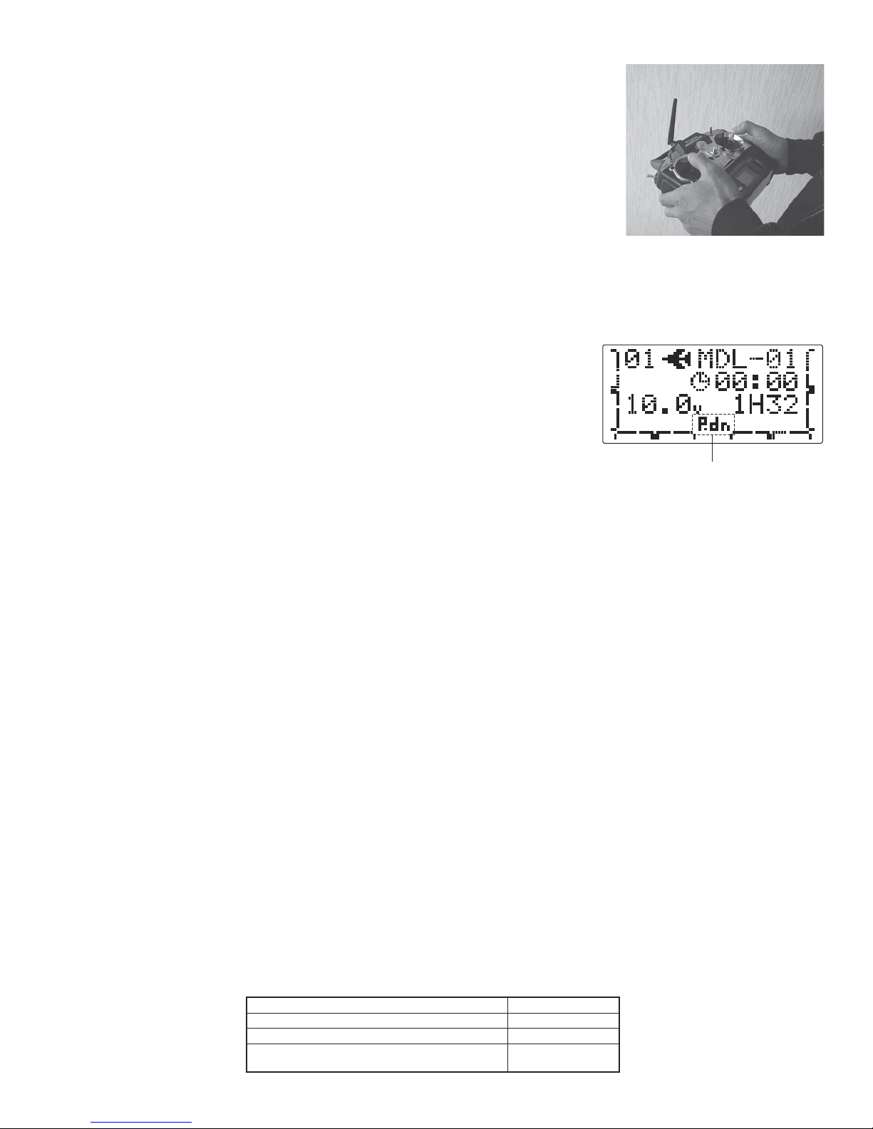
NEVER start taxiing and flying when the “Power Down Mode” is active.
The “Power Down Mode” will reduce your flying range and cause a loss of control. It is a good idea to avoid pointing
the transmitter antenna directly at the model, since the signal is weakest in that direction. (”Power Down Mode”: see
p.18)
Don't fly in the rain! Water or moisture may enter the transmitter through the antenna or stick openings and cause erratic
operation or loss of control. If you must fly in wet weather during a contest, be sure to cover your transmitter with a plastic
bag or waterproof barrier. Never fly if lightning is expected.
6
Page 7

A QUICK INTRODUCTION T O THE 7C SYSTEM
Note that in the text of this manual, beginning at this point, any time we are using a feature’s specialized name or abbreviation
as seen on the screen of the 7C, that name, feature, or abbreviation will be exactly as seen on the radio’s screen, including
capitalization, and shown in a DIFFERENT TYPE STYLE for clarity. Any time we mention a specific control on the radio itself,
such as moving SWITCHA, KNOBVR, or the THROTTLE STICK, those words will be displayed as they are here.
TRANSMITTER:
Large graphic liquid-crystal display panel with 4 buttons and an easy set up turn-and-press Dial for quick, easy setup.
•
All transmitters include all 2 aircraft types with specialized programming for each, including:
•
Airplane (ACRO)
•
V-TAIL
•
ELEVON
•
Air Brake
•
Helicopter (6 swashplate types, including CCPM, see page 61) (H-1,H-2,HR3,HN3,H-3,HE3)
•
2 Idle Ups
•
Revo. Mixing
•
BASIC menu for quick, easy set up of less complex models.
•
Twin Aileron Servos (FLAPRN )
•
Twin Elevator Servos(AI LVATOR )
•
Snap Roll
•
Throttle and Pitch Curves per Condition
•
Gyro Mixing including Separate Settings per Condition
•
Governor Mixing
•
ADVANCE menu for more complex, unique setups.
•
Four electronic TRIM LEVERS for rapid yet precise trim adjustment - no remembering to "store trims" between models
•
and no more "bumped trims" during transport.
TH-CUT (ACRO/HELI) (engine shut off) setups to allow precise engine control for taxi and landings.
•
10 complete model memories
•
New stick design with improved feel, adjustable length and tension.
•
Triple rates available by setting dual rates to 3-position switches.
•
Six SWITCHES and 1 DIALS; assignable in some applications.
•
Trainer system includes the "functional" (F ) setting, which allows the student to use the 7C's mixing, helicopter, and
•
other programming functions even with a 4-channel buddy box. (Optional trainer cord required.)
Permanent memory storage via EEPROM with no backup battery to service or have fail.
•
7CA transmitter features airplane friendly switch layout, with the trainer switch at the left hand, and a notched throttle
•
to minimize throttle changes with rudder input. Defaults to ACRO MODEL TYPE.
7CH transmitter features helicopter-friendly switch layout, with idle-up switch at the left hand, and
•
a smooth, ratchet-less (unsprung) throttle for perfect hovering. Defaults to H-1 MODEL TYPE.
7
Page 8

RECEIVER: R617FS
• Futaba’s small and light weight, powerful 2.4GHz FASST R617FS receiver for flight system can control giant-scale
models as easily as park flyers.
FASST transmitter module, system and receiver
compatibility
* Please note: The TM-7 module is NOT compatible with the R606FS receiver!
.
Transmitter
TM-7 Module — Okay
T6EX 2.4G System Okay Okay
T7C 2.4G System Okay Okay
Receiver
R606FS R617FS/R607FS
SERVOS
• Please see technical specifications page for specifics on the servos included with your system.
• The included receiver is compatible with all J-plug Futaba servos, including retract, winch, and digital servos.
8
Page 9

CONTENTS AND TECHNICAL SPECIFICATIONS
(Specifications and ratings are subject to change without notice.)
Your 7C-2.4GHz (packaged with a 7-channel FASST receiver) system includes the following components:
R617FS Receiver
•
Servos, S3004, S3152 or S3001, with mounting
•
hardware and servo arm assortment
Switch harness
•
Extension cord
•
Receiver battery
•
Transmitter battery or battery holder
•
1
10V wall charger (North America)
•
(The contents depend on the type of set.)
Transmitter T7C-2.4G
7-channel transmitter of FASST system.
Transmitting on 2.4GHz band.
Operating system: 2-stick, 7 channels
Power supply: 9.6V NT8S600B Ni-Cd battery
Current drain: 170 mA
Receiver R617FS
7-channel receiver of FASST system.
Receiving on 2.4GHz band.
Power requirement: 4.8 or 6.0V Ni-Cd battery or
regulated output from ESC, etc.
Current drain: 80mA (at no signal)
Size: 1.64 x 1.08 x 0.36 (41.6 x 27.5 x 9.2 mm)
Weight: 0.34 oz (9.8 g)
Channels: 7
Servo S3152 ( Standard, digital )
Control system: Pulse width control, 1.52 ms neutral
Power requirement: 4.8V (from receiver)
Output torque: 69.4 oz-in(5.0 kg-cm) at 4.8V
Operating speed: 0.22 sec/60 at 4.8V
Size: 1.57 x 0.79 x 1.50 (40 x 20 x 38.1 mm)
Weight: 1.51 oz (42.8 g)
Servo S3001 (Standard, ball-bearing)
Control system: Pulse width control, 1.52 ms neutral
Power requirement: 4.8 - 6.0V (from receiver)
Output torque: 41.7 oz-in (3.0 kg-cm)
Operating speed: 0.22 sec/60
Size: 1.59 x 0.78 x 1.41 (40.4 x 19.8 x 36 mm)
Weight: 1.59 oz (45.1g)
Servo S3004 (Standard, ball-bearing)
Control system: Pulse width control, 1.52 ms neutral
Power requirement: 4.8 - 6.0V (from receiver)
Output torque: 44.4 oz-in (3.2 kg-cm) at 4.8V
Operating speed: 0.23 sec/60 at 4.8V
Size: 1.59 x 0.78 x 1.41 (40.4 x 19.8 x 36 mm)
Weight: 1.31 oz (37.2 g)
Note: NEVER use dry battery for R617FS as it
cause malfunction.
9
Page 10

The following additional accessories are available from your dealer. Refer to a Futaba catalog for more information:
NT8S Transmitter battery pack - the (600mAh) transmitter Ni-Cd battery pack may be easily exchanged with a fresh
•
one to provide enough capacity for extended flying sessions.
Trainer cord - the optional training cord may be used to help a beginning pilot learn to fly easily by placing the instructor on
•
a separate transmitter. Note that the 7C transmitter may be connected to another 7C system, as well as to many other models
of Futaba transmitters. The 7C transmitter uses the newer rectangular type cord plug. Both new-to-new and new-to-round plug
style trainer cords are available.
FTA8 Neckstrap - a neckstrap may be connected to your T7C system to make it easier to handle and improve your flying
•
precision, since your hands won't need to support the transmitter's weight.
Y-harnesses, servo extensions, etc - Genuine Futaba extensions and Y-harnesses, including a heavy-duty version with heavier
•
wire, are available to aid in your larger model and other installations.
5-cell (6.0V) receiver battery packs - All Futaba airborne equipment (except that which is specifically labeled otherwise) is
•
designed to work with 4.8V (Ni-Cd 4 cells) or 6.0V (Ni-Cd 5 cells or alkaline 4 cells). Using a 6.0V pack increases the current
flow to the servos, which accelerates their rate of response and their torque. However, because of this faster current draw, a 5cell battery pack of the same mAh rating will last approximately ¾ the time of a 4-cell pack.
Gyros - a variety of genuine Futaba gyros are available for your aircraft or helicopter needs. See p. 56 for aircraft or
•
p. 73 for helicopter gyro information.
10
Page 11
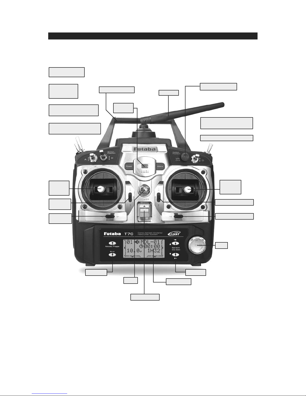
TRANSMITTER CONTROLS - AIRPLANE
SW(F)
Snap Roll or
Trainer Switch
SW(E)
Landing Gear
Switch
/CH5
SW(B)
Rudder Dual Rate Switch
/CH7
SW(A)
Elevator Dual Rate Switch
/TH-CUT/P-MIX/TIMER
Carrying Handle
Power
LED*
Antenna
VR
Flap Trim Control
This controls CH6, and if flaperon mixing
is activated controls the flap.
SW(G)
Elevator - Flap Mixing or
Airbrake Mixing Switch
SW(D)
Aileron Dual Rate Switch
Rudder
/Throttle
Stick
Throttle
Trim Lever
Rudder
Trim Lever
Edit Keys
Hook
(for optional neckstrap)
Power Switch
(Up position: ON)
Edit keys
LCD Panel
Elevator
/Aileron
Stick
Elevator Trim Lever
Aileron Trim Lever
Dial
This figure shows the default switch assignments for a Mode 2 system as supplied by the factory.
You can change many of the switch positions or functions by selecting a new position within
the setting menu for the function you wish to move. (Example: move aileron dual rates to switch G
to create triple rates. See p. 33 for details.)
* Power LED blinks to indicate if any mix switches are activated.
11
Page 12
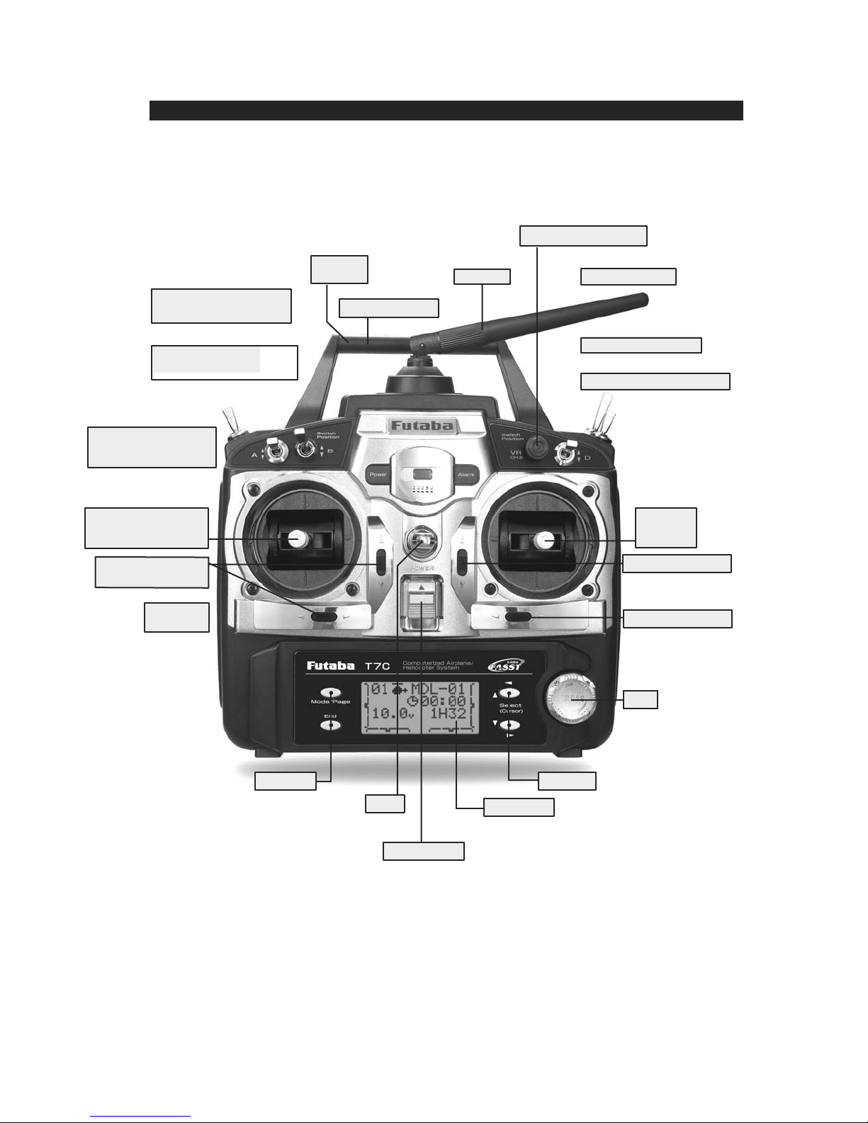
TRANSMITTER CONTROLS - HELI
VR
Hovering - Pitch Knob
SW(B)
Rudder Dual Rate Switch
/CH7
SW(A)
Elevator Dual Rate Switch
/TH-CUT/P-MIX/TIMER
SW(E)
Idle-up 1&2 Switch
/CH5/OFFSET/GYRO
Throttle/Collective
Pitch & Rudder Stick
Throttle/Collective
Trim Lever
Rudder
Trim Lever
Power
LED*
Carrying Handle
Antenna
SW(H)
Trainer Switch
SW(G)
Throttle - Hold Switch
SW(D)
Aileron Dual Rate Switch
Elevator
/Aileron
Stick
Elevator Trim Lever
Aileron Trim Lever
Edit Keys
This figure shows the default switch assignments for a Mode 2 system as supplied by the factory.
You can change many of the switch positions or functions by selecting a new position within
the setting menu for the function you wish to move.
* Power LED blinks to indicate if any mix switches are activated.
Hook
(for optional neckstrap)
Power Switch
(Up position: ON)
Dial
Edit keys
LCD Panel
12
Page 13
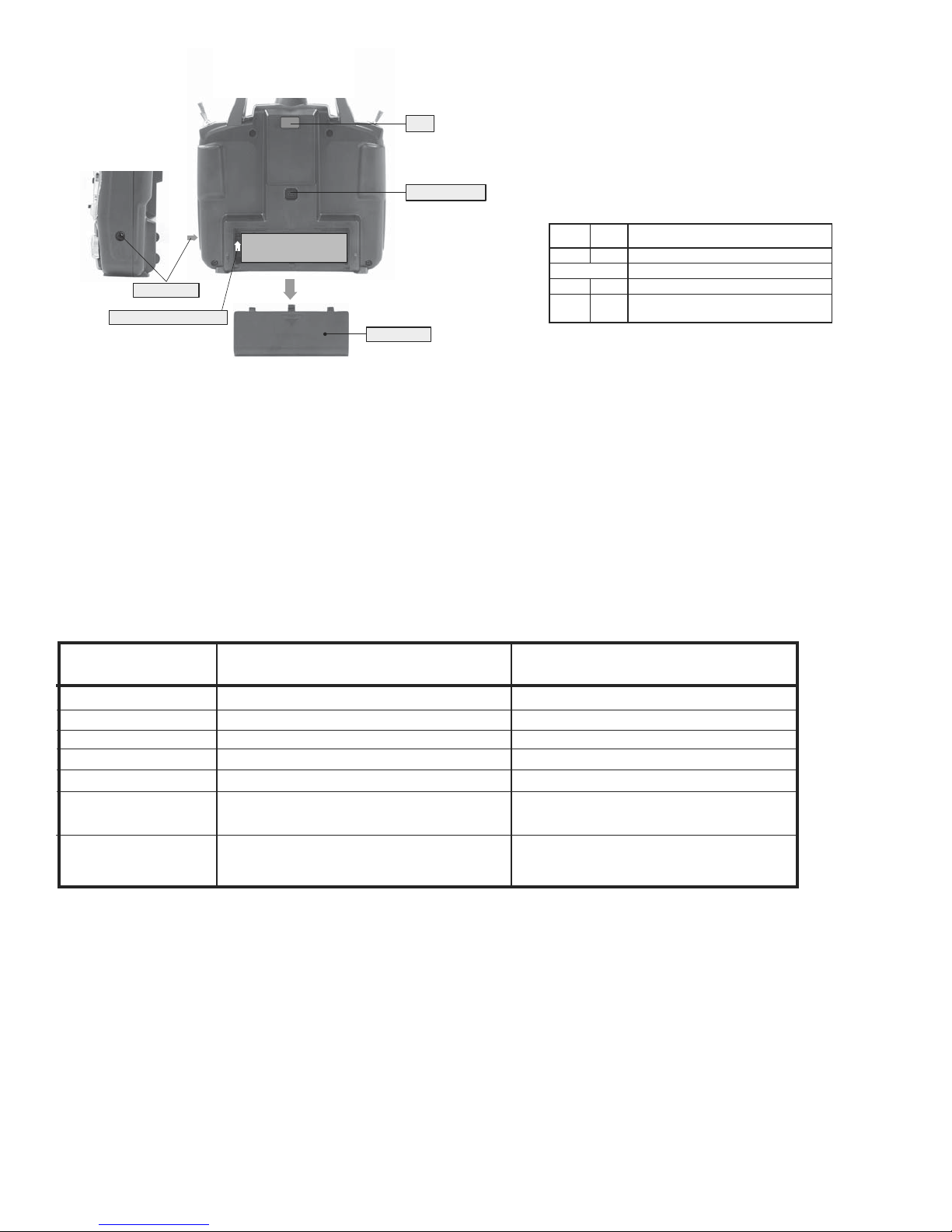
LED
Trainer connector
LED indication
When the transmitter is powered up, the LEDs on
the rear of the transmitter will begin to glow or
blink accordingly. The chart below provides you
with an easy reference as to the meaning of the
LEDs.
Ni-Cd battery pack
Charging jack
Battery connector location
Battery cover
Green Red Status
Solid Solid Initializing (When Power Up)
Alternate blink Check RF condition nearby
Solid Off RF power on
Solid Blink
RF power on (Power reduced to perform the
range check function.)
NOTE: If you need to remove or replace the transmitter battery, do not pull on its wires to remove it. Instead,
gently pull on the connector's plastic housing where it plugs into the transmitter.
SWITCH ASSIGNMENT TABLE
The factory default functions activated by the switches and knobs for a Mode 2 transmitter are shown below.
•
Most 7C functions may be reassigned to non-default positions quickly and easily.
•
Basic control assignments of channels 5 & 7 are quickly adjustable in PARA (see p. 28). For example, the channel 5
•
servo, which defaults to S
WITCH E for retract use, can easily be unassigned (NULL) to allow for easy use as a second
rudder servo in a mix, or to a dial for bomb door or other control.
Note that most functions need to be activated in the programming to operate.
•
Mode 1 transmitter functions are similar but reverse certain switch commands. Always check that you have the desired
•
switch assignment for each function during set up.
Switch/Knob Airplane (ACR O) Helicopter (HELI)
A or H Tx.
WITCH A elevator dual rate elevator dual rate
S
Switch B rudder dual rate rudder dual rate
WITCH D aileron dual rate aileron dual rate
S
Switch E
Switch F
WITCH G OR E* idle-up 1 and 2,
S
NOB VR flap/ch 6 HOVERING PIT
K
OR G* landing gear/ch 5 throttle hold
OR H* snap roll/trainer trainer
up = ELE-FLP on
down = AIRBRAKE
on
ch5/OFFSET/GYRO
(flap trim if FLAPERON on)
* On the 7CA (mode 2) transmitters, the Top Left Switches are spring-loaded switch and 2-position switch. On the 7CA (mode 1) and 7CH
transmitters, the Top Left Switch is a 3-position with the spring loaded switch on the top right.
13
Page 14
r
RECEIVER AND SERVO CONNECTIONS
Receiver Aircraft (
A
CRO
) Helicopter (
H
ELI
)
Output and
Channel
1 ailerons/combined right flap & aileron
1
aileron (cyclic roll)
2 elevator elevator (cyclic pitch)
3 throttle throttle
4 rudder rudder
5 spare/landing gear/combined left flap and aileron
6 spare/ flap(s)/combined left flap and aileron pitch (collective pitch)
7 spare/combined left flap and aileron spare/governor
1
Flaperon mode. (See p. 42).
2
Within flaperon, the second aileron servo can be assigned to channel 5, 6 or 7. (See p. 42)
1,2
1,2
1,2
spare/gyro
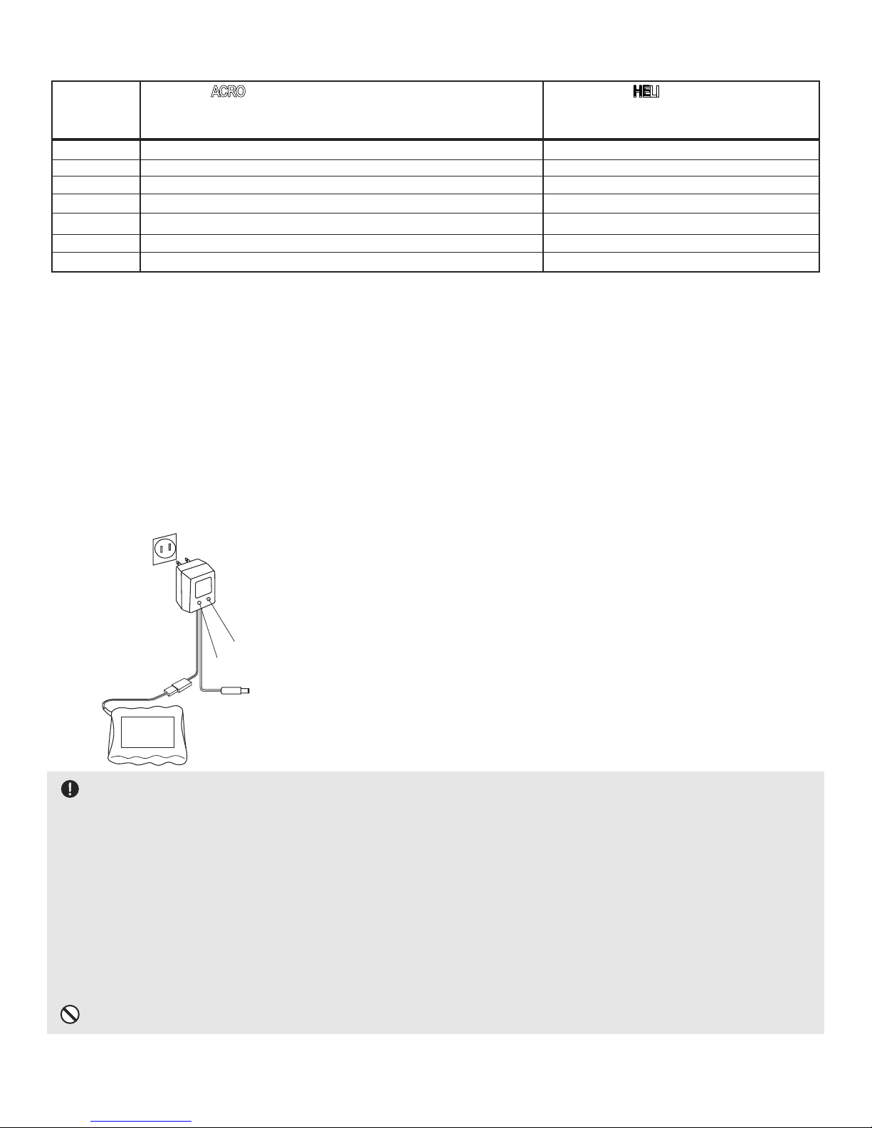
CHARGING THE Ni-Cd BATTERIES
Charging Your System’s Batteries
1. Connect the transmitter charging jack and airborne Ni-Cd batteries to the transmitter and receiver connectors of the charger.
2. Plug the charger into a wall socket.
3. Check that the charger LED lights.
The initial charge, and any charge after a complete discharge,
should be at least 18 hours to ensure full charge. The batteries
Charger
should be left on charge for about 15 hours when recharging the
standard NR-4J, NR-4RB and NT8S600B Ni-Cd batteries.
TX: Transmitter charging indicato
RX: Receiver charging indicator
To transmitter charging jack
We recommend charging the batteries with the charger
supplied with your system. Note that the use of a fast charger
Receiver Ni-Cd battery
may damage the batteries by overheating and dramatically
reduce their lifetime.
You should fully discharge your system's Ni-Cd batteries periodically to prevent a condition called memory. For
example, if you only make two flights each session, or you regularly use only a small amount of the batteries' capacity , the
memory effect can reduce the actual capacity even if the battery is fully charged. You can cycle your batteries with a commercial
cycling unit*, or by leaving the system on and exercising the servos by moving the transmitter sticks until the transmitter shuts
itself off. Cycling should be done every four to eight weeks, even during the winter or periods of long storage. Keep track of the
batteries' capacity during cycling; if there is a noticeable change, you may need to replace the batteries.
*Note that your 7C transmitter system is protected from accidental reverse polarity, power surges and other electrical
damage by a diode. The transmitter battery must be removed from the system to cycle. The battery easily unplugs from the
battery compartment and has a standard J-plug for easy cycling.
DO NOT attempt to charge your 8-cell transmitter pack on the 4-cell receiver plug of the wall charger!
14
Page 15
Adjusting the length of the non-slip control sticks
You may change the length of the control sticks to make your transmitter more
Stick tip A Locking piece B
comfortable to hold and operate. To lengthen or shorten your transmitter’s sticks,
first unlock the stick tip by holding locking piece B and turning stick tip A
counterclockwise. Next, move both pieces up or down (to lengthen or shorten).
When the length feels comfortable, lock the position by turning locking piece B
counterclockwise, while holding piece A.
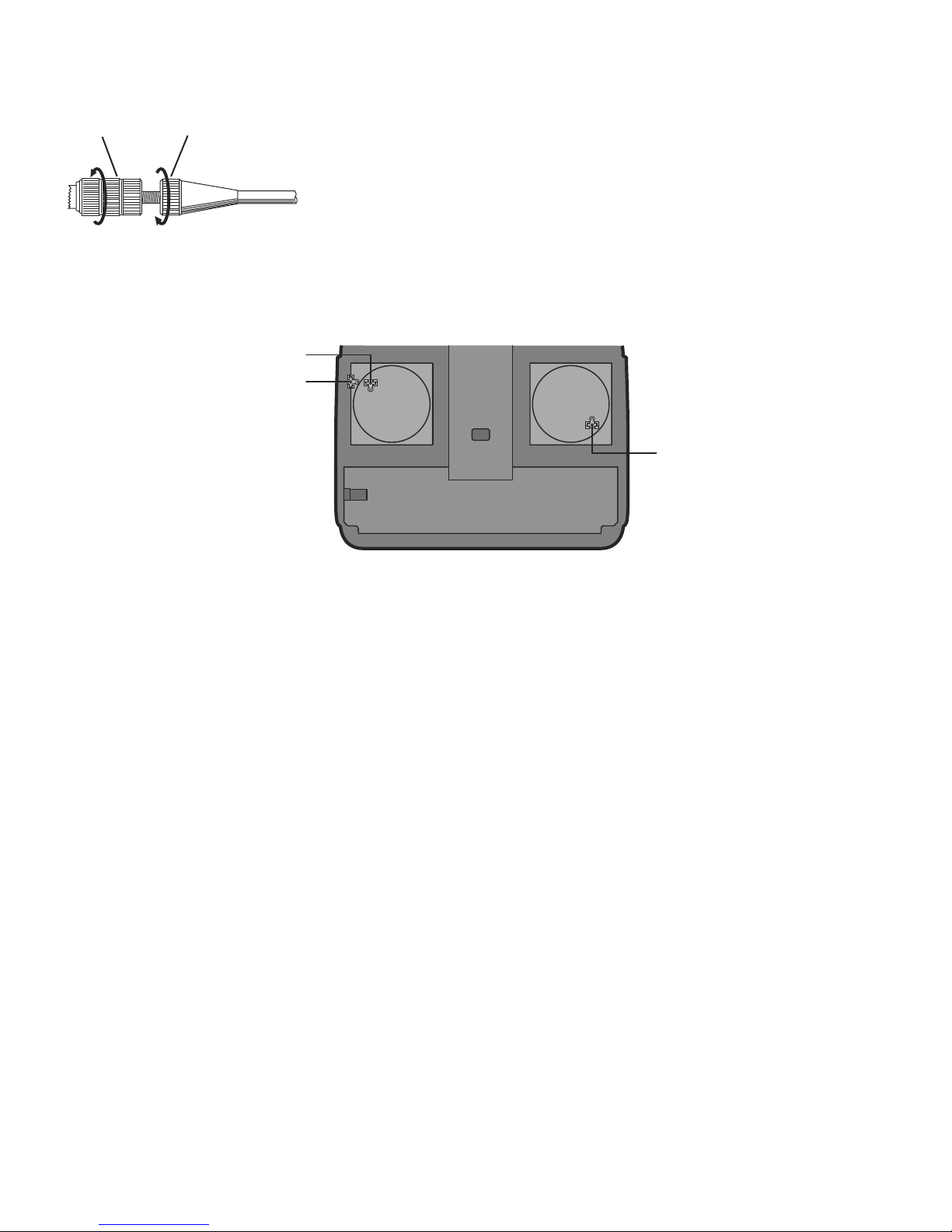
Stick lever tension adjustment
Aileron
Elevator
Stick Stick
Mode 2 transmitter with rear cover removed.
You may adjust the tension of your sticks to provide the feel that you prefer for flying.
Rudder
To adjust your springs, you’ll have
to remove the rear case of the transmitter. First, remove the battery cover on the rear of the transmitter. Next, unplug the
battery wire and remove the battery from the transmitter.
Next, using a screwdriver, remove the four screws that hold the transmitter’s rear cover in position, and put them in a safe
place. Gently ease off the transmitter’s rear cover.
Now you'll see the view shown in the figure above.
Using a small Phillips screwdriver, rotate the adjusting screw for each stick for the desired spring tension. The tension
increases when the adjusting screw is turned clockwise.
When you are satisfied with the spring tensions, reattach the transmitter's rear cover. Check that the upper printed circuit
board is on its locating pins.
When the cover is properly in place, reinstall and tighten the four screws. Reinstall the battery cover.
Adjusting Display Contrast
To adjust the display contrast, from the home menu press and hold the End button.
Turn the dial while still holding End button:
clockwise to brighten
counterclockwise to darken the display
Let go off the dial and the button.
Changing Modes:
Hold down the Mode and End buttons while turning on the transmitter. The screen reads "STK-MD". Change this to
the correct mode. Note that this will NOT change the throttle and elevator rachets, etc. Those are mechanical changes
that must be done by a service center.
15
Page 16

RADIO INSTALLATION
Follow these guidelines to properly mount the servos, receiver and battery.
• Make certain the
alignment tab
on the battery, switch and servo connectors is oriented correctly and “keys” into the corresponding
notch in the receiver or connectors before plugging them in. When unplugging connectors, never pull on the wires. Always pull on the
plastic connector instead.
• If any servo wires are not long enough to reach the receiver, servo extension wires (available separately) may be used.
• Always mount the servos with the supplied
rubber grommets
. Do not over tighten the
screws. No part of the servo casing should contact the mounting rails, servo tray or any
Servo
Rubber
grommet
Servo
Rubber
grommet
other part of the airplane/helicopter structure. Otherwise, vibration will be transmitted to
the servo causing premature wear and/or servo failure.
• Note the small numbers (1, 2, 3, 4) molded into each arm on the Futaba 4-arm servo arms. The numbers indicate
how many degrees each arm is “off” from 90 degrees to correct for minute manufacturing deviations from servo to
servo.
• To center the servos, connect them to the receiver and turn on the transmitter and receiver.
Center the trims on the transmitter, then ¿nd the arm that will be perpendicular to the pushrod
when placed on the servo.
• After the servos are installed, operate each servo over its full travel and check that the pushrods and servo arms do not bind or contact
each other. Also make sure the controls do not require excess force to operate. If there is an objectionable buzzing sound coming from
a servo, there is probably too much resistance in the control. Find and correct the problem. Even if there is no servo damage, excess
battery drain will result.
• Use the
mounting plate
from the receiver on/off switch as a template for the cutout and screw holes. Mount the switch on the side of
the fuselage opposite the engine exhaust, and where it won’t be inadvertently turned on or off during handling or storage. Be certain the
switch moves without restriction and “snaps” from ON to OFF, and that the cutout allows
full motion
of the switch in
both
directions.
• When you install the switch harness to the helicopter, please use the switch cover. Generally sandwich the frame by switch and switch
cover and securely tighten the screws. Different models might require different installations. In that case, please follow the model
instruction manual.
• To prevent the servo lead wires from being broken by vibration during flight,
provide a margin so that the wire sticks out slightly and fasten it at suitable points.
In addition, periodically check the wire during daily maintenance.
Margin in the lead wire.
Fasten about 5-10cm
from the servo outlet
so that the lead wire
is neat.
16
Page 17
•
IMPORTANT
: Since the 2.4GHz have different characteristics than that of the conventional 27MHz and 72MHz frequencies, please
read this section carefully to enjoy safe Àight with the 2.4GHz system.
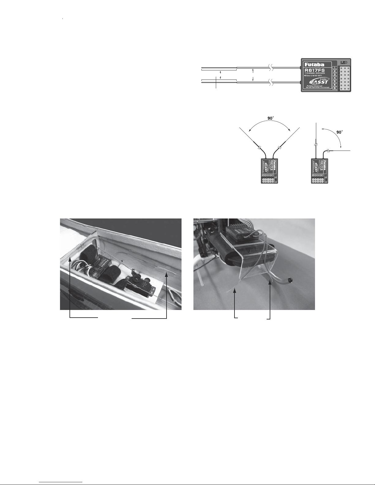
Receiver's Antenna Installation:
• The R617FS has two antennas. These antennas have a diversity
function to decrease the chance of a receiving error.
• Since the wavelength of the 2.4GHz is much shorter than that of the
Antenna
Coaxial cable
conventional frequencies 27MHz and 72MHz, it is very susceptible to
loss of signal which results in a receiving error. In order to avoid this
phenomenon, the R617FS adopted a diversity antenna system.
*Must be kept as straight as possible.
R617FS Receiver
• To obtain the best results of the diversity function, please refer to the following instructions;
1. The two antennas must be kept as straight as possible. Otherwise it will reduce the
effective range.
2. The two antennas should be placed at 90 degrees to each other.
This is not a critical ¿gure, but the most important thing is to keep the antennas away
from each other as much as possible.
Larger models can have large metal objects that can attenuate the RF signal.In this
case the antennas should be placed at both sides of the model. Then the best RF signal
condition is obtained at any Àying attitude.
3. The antennas must be kept away from conductive materials, such as metal and carbon by at least a half inch. The coaxial part of the
antennas does not need to follow these guidelines, but do not bend it in a small radius.
4. Keep the antennas away from the motor, ESC, and other noise sources as much as possible.
Antenna Antenna
*The two antennas should be placed at 90 degrees to each other.
*The main purpose of the photo demonstrates how the antenna should be placed.
For actual installation the receiver must be wrapped with a sponge or placed with
floating material to protect it from vibration.
• The receiver contains precision electronic parts. It is the most delicate radio component on-board the model and should be protected
from vibration, shock and temperature extremes. To protect the receiver, wrap it in R/C foam rubber or other vibration-absorbing
material. If appropriate, waterproof the receiver by placing it in a plastic bag and closing the open end with a rubber band before
wrapping it in foam. If moisture enters the receiver, intermittent operation or a failure may result. Wrapping the receiver in a plastic bag
also protects it from fuel and exhaust residue which, in some models, can work its way into the fuselage.
17
Page 18
Transmitter Antenna
1. The transmitter antenna is adjustable so please make sure that the antenna is never pointed directly
at the model when Àying as this creates a weak signal for the receiver.
2. Keep the antenna perpendicular to the transmitter's face to create a better RF condition for the
receiver. Of course this depends on how you hold the transmitter, but in most cases, adjusting the
transmitter antenna so that it is perpendicular to the face will give the best results. Please adjust the
transmitter antenna to the way you hold the transmitter.
3.
NEVER
grip the antenna when Àying as this degrades RF quality.
Range Check the Radio
A range check
be performed before the
must
Àight of a new model. It is not necessary to do a range check before every Àight (but
first
is not a bad idea to perform a range check before the ¿UVt Àight of each day). A range check is the ¿nal opportunity to reveal any radio
malfunctions, and to be certain the system has adequate operational range.
1. We have installed a special "Power Down Mode" for doing a ground range check. To activate
the "Power Down Mode" please hold down the
During this mode, the RF power is reduced so the range test can be performed.
and then turn the transmitter switch on.
Dial
When this
mode is active the red LED on the back of the transmitter starts blinking and the green LED
is solid. In addition, when the mode is activated the transmitter gives users a warning with a
beep sound every 3 seconds, and visual indication.
2. Walk away from the model while simultaneously operating the controls. Have an assistant
stand by the model and signal what the controls are doing to confirm that they operate
flash
correctly. You should be able to walk approximately 30 - 50 paces from the model without
losing control.
3. If everything operates correctly, return to the model. Set the transmitter in a safe, yet accessible location so it will be within reach after
starting the engine. Be certain the throttle stick is all the way
, then start the engine. Perform another range check with your
down
assistant holding the plane and the engine running at various speeds. If the servos jitter or move inadvertently, there may be a problem.
Do not fly
the plane! Look for loose servo connections or binding pushrods. Also be certain that the battery has been fully charged.
4. The "Power Down Mode" continues for 90 seconds and after that the power will go back to the normal level.
To exit the "Power Down Mode" before the 90 seconds, press the
again. This mode is available 1 time only so if you need to re-use
Dial
this function the transmitter power must be cycled.
5.
NEVER
start Àying when the "Power Down Mode" is active.
Link Procedure
Each transmitter has an individually assigned, unique ID code. In order to start operation, the receiver must be linked with the ID code of
the transmitter with which it is being paired. Once the link is made, the ID code is stored in the receiver and no further linking is necessary
unless the receiver is to be used with another transmitter. When you purchase another R617FS, this procedure is necessary; otherwise the
receiver will not work.
1. Place the transmitter and the receiver close to each other within one (1) meter
2. Turn on the transmitter.
3. Check the LED that is placed on the back side of the transmitter to see if the RF signal is active. When the green LED is ON solid, the
RF signal is being sent.
4. Turn on the receiver.
5. Press down the "
Easy Link(ID SET)
" switch for more than one second, and release the switch. The receiver starts the linking
operation.
6. When the linking is complete, the LED in the receiver will change to solid green. Please con¿Um that the servos will now operate by
your transmitter. Please refer to the table below for the LED status of the receiver's condition.
No signal reception Red : On
Receiving signals Green: On
Receiving signals, but ID is unmatched. Green: Blink
Unrecoverable failure (EEPROM, etc.)
Red and Green
turn on alternately.
18
Page 19

TRANSMITTER DISPLAYS & BUTTONS
When you first turn on your transmitter, a confirmation double beep sounds, and the screen shown below appears. Before
flying, or even starting the engine, be sur
e that the model type and name appearing on the display matches the model that
you are about to fly! If you are in the wrong model memory, servos may be reversed, and travels and trims will be wrong,
leading to an immediate crash.
Edit buttons and Start-up Screen (appears when system is first turned on):
Model
Model
number
type
Model
name
Elevator trim
display
Throttle trim
display
Mode
key
End
key
Rudder trim
display
Battery voltage
Aileron trim
display
Select
keys
Dial
MODE/PAGE BUTTON: (key)
Press and hold M
BASIC and ADVANCE menus. HELI only: Press M
ODE BUTTON for one second to open programming menus. Press MODE BUTTON to switch between
ODE BUTTON to scroll between conditions in certain functions.
END BUTTON: ( key)
Press END BUTTON to return to previous screen. Closes functions back to menus, closes menus to start-up screen.
SELECT/CURSOR BUTTONS: ( key)
Press SELECT/CURSOR BUTTON to scroll through and select the option to edit within a function.
Press S
ELECT/CURSOR BUTTON to page up/page down within BASICor ADVANCE menu.
Turn Dial:
Turn D
IAL clockwise or counterclockwise to quickly scroll through functions within each menu.
Turn DIAL clockwise or counterclockwise to scroll through choices within an option of a function (for example, to
select which switch controls dual/triple rates).
Press Dial:
Press DIAL to select the actual function you wish to edit from the menu.
Press DIAL and hold one second to confirm major decisions, such as the decision to: select a different model from
memory, copy one model memory over another, trim reset, store channel position in FailSafe, change model type, reset
entire model. System will ask if you are sure. Press D
IAL again to accept change.
19
Page 20
WARNING & ERROR DISPLAYS
An alarm or error indication may appear on the display of your transmitter for several reasons, including when the
transmitter power switch is turned on, when the battery voltage is low, and several others. Each display has a unique sound
associated with it, as described below.
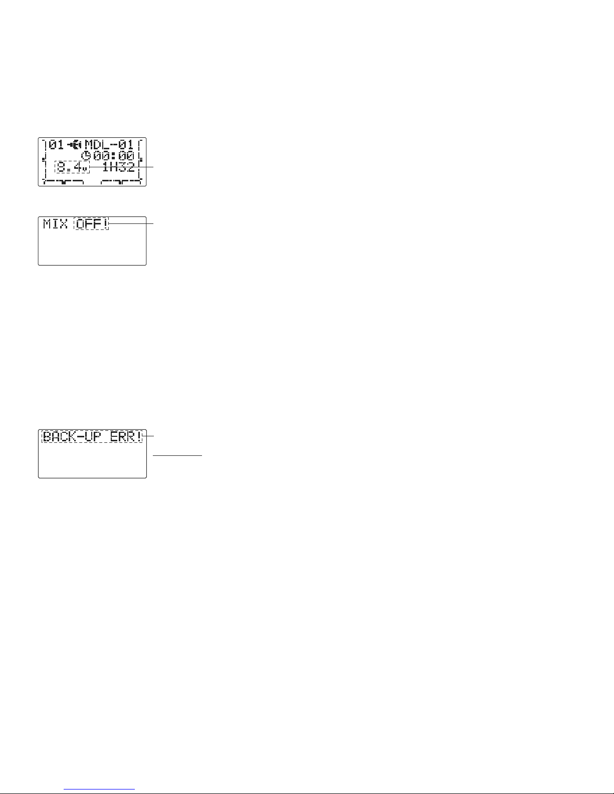
LOW BATTERY ERROR: Warning sound: Continuous beep until transmitter is powered off.
The LOW BATTERY warning is displayed when the transmitter battery voltage drops below 8.5V.
Land your model as soon as possible before loss of control due to a dead battery.
flash
MIXER ALERT WARNING: Warning sound: 5 Beeps (repeated until problem resolved or overridden)
flash
The MIXER ALERT warning is displayed to alert you whenever you turn on the transmitter with any of the
mixing switches active. This warning will disappear when the offending switch or control is deactivated.
Switches for which warnings will be issued at power-up are listed below:
ACRO: Throttle cut, snap roll, airbrake HELI: Throttle hold, idle-up
If turning a switch OFF does not stop the mixing warning: When the warning does not stop even when the mixing switch
indicated by the warning display on the screen is turned off, the functions described previously probably use the same
switch and the OFF direction setting is reversed. In short, one of the mixings described above is not in the OFF state. In
this case, reset the warning display by pressing both S
ELECT BUTTONS simultaneously. Then change one of the switch
settings of the mixings duplicated at one switch.
BACKUP ERROR: Warning sound: 4 beeps (repeated continuously)
The BACKUP ERROR warning occurs when the transmitter memory is lost for any reason. If this occurs, all of the data will
be reset when the power is turned on again.
flash
Do not fly when this message is displayed - all programming has been erased and is not
available. Return your transmitter to Futaba for service.
20
Page 21

AIRCRAFT (ACRO) MENU FUNCTIONS
Please note that all BASIC menu functions are the same for airplanes (ACRO) and helicopters (H-1/H-2/HR3/HN3/H-3/HE3);
the helicopter BASIC menu includes additional features (swashplate adjustment and throttle/pitch curves and revo for Normal
flight mode) that are discussed in the Helicopter section.
AIRPLANE FUNCTIONS ............................................. 21
Map of Functions ........................................................ 22
Quick Guide to Setting up a 4-channel Airplane........ 23
ACRO BASIC MENU FUNCTIONS ............................... 25
MODEL Submenu: MODEL SEL., COPYand NAME....... 25
Parameter(PARA.) Submenu: RESET,TYPE,CH5 & CH7 28
Servo REVERSE........................................................... 30
End Point (E. POINT) ................................................... 31
Idle Management: THR-CUT........................................ 32
DualRates and Exponential (D/R,EXP) ........................ 33
TIMER........................................................................... 36
TRAINER ...................................................................... 37
TRIM............................................................................. 38
SUB-TRIM..................................................................... 39
Fail Safe (F/S) (Throttle channel only) ...................... 40
ACRO ADVANCE MENU FUNCTIONS.......................... 41
Wing types................................................................... 41
Flaperon(FLAPRN).................................................... 42
Flap Trim(FL-TRIM).................................................. 43
Tail types ..................................................................... 44
ELEVON.................................................................... 44
Twin Elevator Servos(AI LVATOR )............................ 45
V-TAIL ....................................................................... 46
SNAP ROLL................................................................. 47
Mixes: definitions and types ....................................... 48
ELE-FLP.................................................................... 49
Air Brake(A.BRAKE) ................................................ 52
FLP-ELE.................................................................... 50
AIL-RUD.................................................................... 51
Prog. Mixes(P-MIX1-3).............................................. 53
21
Page 22
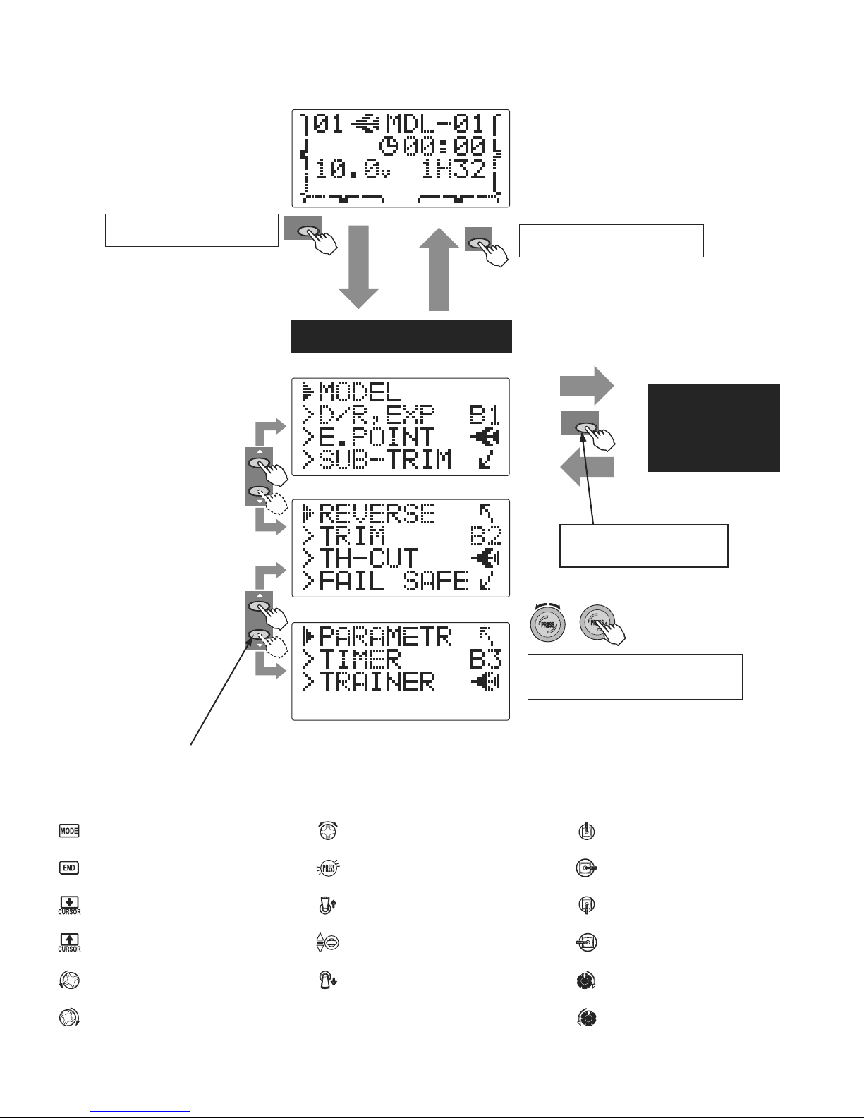
(Startup screen)
To enter the Basic Menu, press the
ode key for one second.
M
Select
(Cursor)
Select
(Cursor)
Mode/Page
( for one second)
ACRO Basic Menu
(Basic Menu 1)
(Basic Menu 2)
(Basic Menu 3)
End
To return to the Startup screen, press the
End key.
Mode/Page
ACRO
ADVANCE
Menu
Press Mode/Page key to toggle back
and forth between BASIC and
ADVANCE menus.
Press Select/Cursor keys to page up and down through the 3 pages of
screens in each menu.
Mode/Page Select
End Selection
Cursor Down
Cursor Up
Dial Left
Dial Right or Left
Press Button
Switch Up
Switch at Center
Switch Down
Dial Right
Turn the
Dial
highlight function in Menu screen. Then press the
Dial to choose that function.
clockwise or counterclockwise to
Stick Up
Stick Right
Stick Down
Stick Left
Turn Knob Right
Turn Knob Left
22
Page 23
A QUICK GUIDE: GETTING STARTED WITH A BASIC 4-CHANNEL AIRCRAFT
This guide is intended to help you get acquainted with the radio, to give you a jump start on using your new radio, and to give you
some ideas and direction in how to do even more than you may have already considered. It follows our basic format of all
programming pages: a big picture overview of what we accomplish; a "by name" description of what we're doing to help acquaint
you with the radio; then a step-by-step instruction to leave out the mystery when setting up your model.
For additional details on each function, see that function's section in this manual. The page numbers are indicated in the
goals column as a convenience to you.
See p.22 for a legend of symbols used.
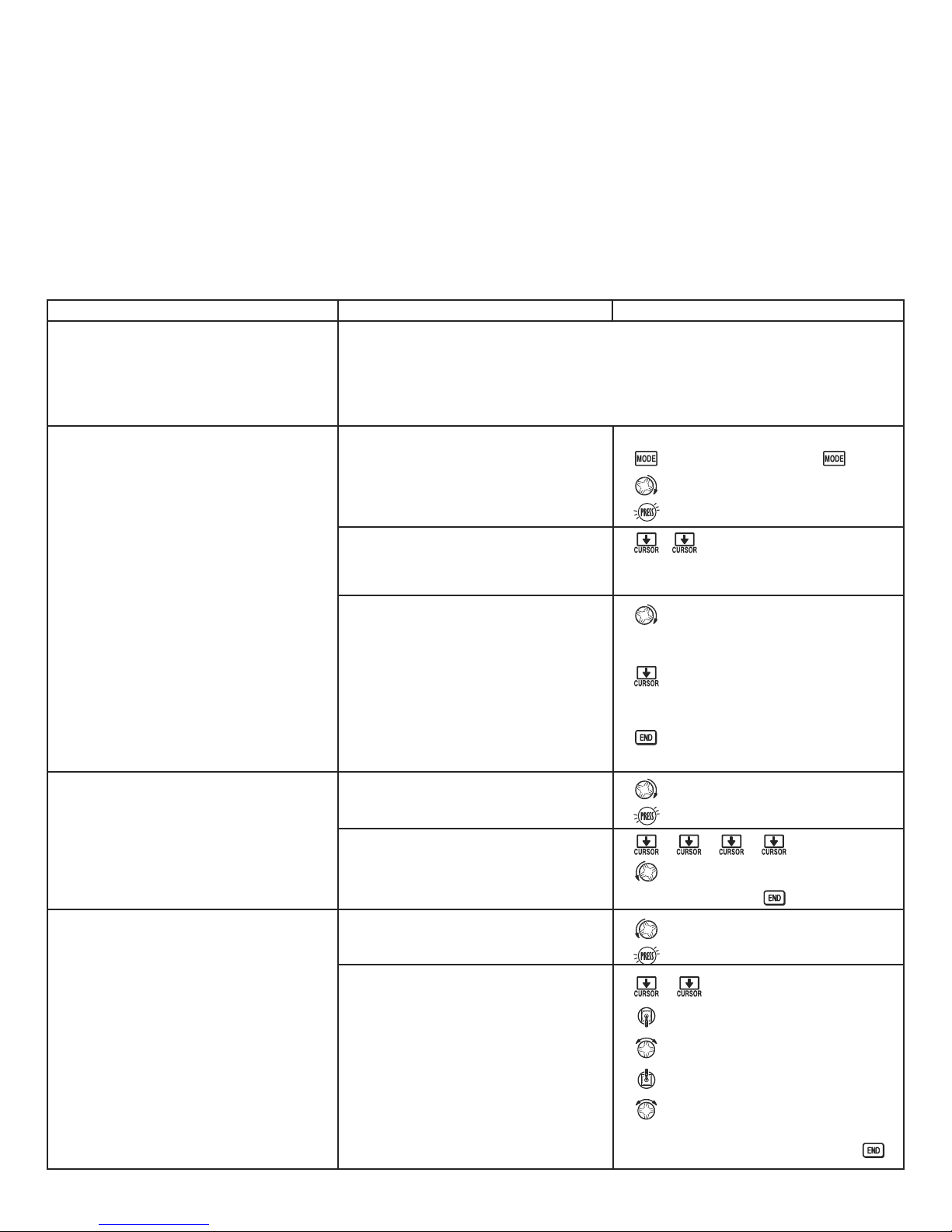
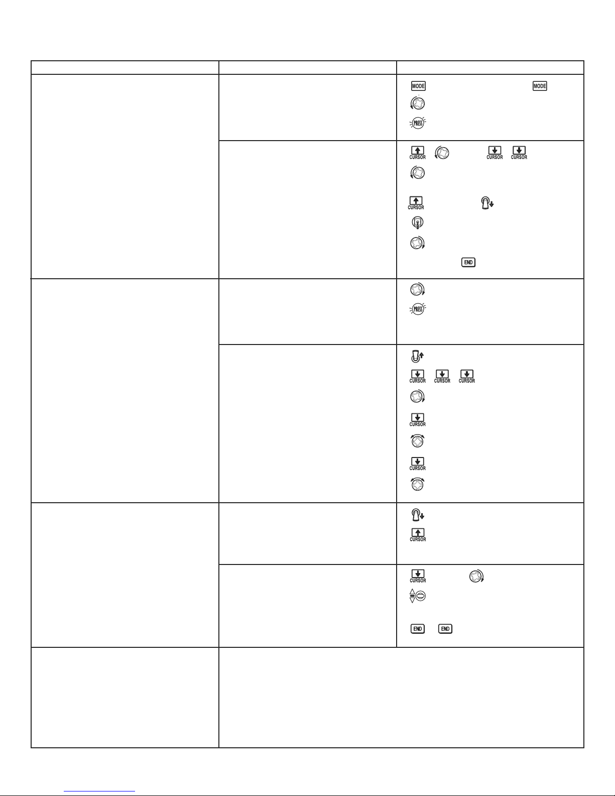
GOALS of EXAMPLE STEPS INPUTS for EXAMPLE
Prepare your aircraft. Install all servos, switches, receivers per your model's instructions.
Turn on transmitter then receiver; adjust all linkages so surfaces are nearly centered.
Mechanically adjust all linkages as close as possible to proper control throws.
Check servo direction.
Make notes now of what you will need to change during programming.
Name the model.
P. 27.
Open the BASIC menu, then open the
MODEL submenu.
Turn on the transmitter.
for 1 second.
(If ADVANCE, again.)
[Note that you do not need to do
anything to "save" or store this data.
Only critical changes such as a MODEL
RESET require additional keystrokes to
accept the change.]
Reverse servos as needed for proper
control operation.
P. 30.
Adjust Travels as needed to match
model's recommended throws (usually
listed as high rates). P. 31.
Go to MODEL NAME.
Input aircraft's name.
Close the MODEL submenu.
In the BASIC menu, open (servo)
REVERSE.
Choose desired servo and reverse its
direction of travel. (Ex: reversing
rudder servo.)
From BASIC menu, choose END POINT.
Adjust the servo's end points.
(Ex: throttle servo)
Close the function.
as needed to highlight MODEL.
to choose MODEL.
to NAME.
(First character of model's name is flashed.)
to change first character.
When proper character is displayed,
to move to next character.
Repeat as needed.
to return to BASIC menu.
4 steps to REVERSE.
to choose REVERSE.
to CH4: RUDD.
so REVis selected.
Repeat as needed.
2 steps to END POINT.
to choose END POINT.
to THROTTLE.
T
HROTTLE STICK.
until carb barrel closes as desired.
THROTTLE STICK.
until throttle arm just opens carb
fully at full THROTTLE STICK.
Repeat for each channel as needed.
23
Page 24
With digital trims you don't shut the engine off with THROTTLE TRIM. Let's set up throttle cut (THR-CUT) now.
GOALS of EXAMPLE STEPS INPUTS for EXAMPLE
THR-CUT shuts the engine off completely
with the flip of a switch. P. 32.
From the BASICmenu, choose THR-CUT.
for 1 second.
to THR-CUT.
(If ADVANCE, again.)
to choose THR-CUT.
Set up dual/triple rates and
exponential (D/R,EXP).
P. 33.
(Note that in the middle of
the screen is the name of the
channel AND the switch position you
are adjusting. Two or even THREE
rates may be set per channel by
simply choosing the desired switch
and programming percentages with
the switch in each of its 2 or 3
positions.)
Activate, assign S
WITCH and adjust.
Close the function.
From the BASIC menu, choose
D/R,EXP.
Choose the desired control, and set the
first (Ex: high) rate throws and
exponential.
to OFF.toSW.
to desired switch and position.
(default: A and down position)
to RATE . A to down position.
HROTTLE STICK.
T
until throttle barrel closes
completely.
to D/R,EXP.
to choose D/R,EXP.
A to up position.
to CH> .
to choose CH>2 (elevator).
to D/R .
to set desired percentage.
Where next?
to EXP.
to set desired percentage.
Set the second (low) rate throws and
exponential.
A to down position.
to D/R .
Repeat steps above to set low rate.
Optional: change dual rate switch
to SW. to G or E.
assignment. Ex: elevator to switch G
(7CA) or E (7CH) with 3 positions.
G or E to center position.
Repeat steps above to set 3rd rate.
(Other functions you may wish to set up for your model.)
TRAINER p. 37.
Multiple wing and/or tail servos: see wing types and tail types, p. 41, 44.
Elevator-to-flap, flap-to-elevator , and other programmable mixes p. 48.
Retractable Gear, Flaps on a Switch, Smoke systems, kill switches,
auxiliary channel (ch5 and ch7) setups. p. 30.
24
Page 25
A LOOK AT THE RADIO'S FUNCTIONS STEP BY STEP
MODEL submenu: includes three functions that manage model memory: MODEL SELECT, MODEL COPY and MODEL NAME.
Since these functions are all related, and are all basic features used with most models, they are together in the MODEL
submenu of the BASIC menu.
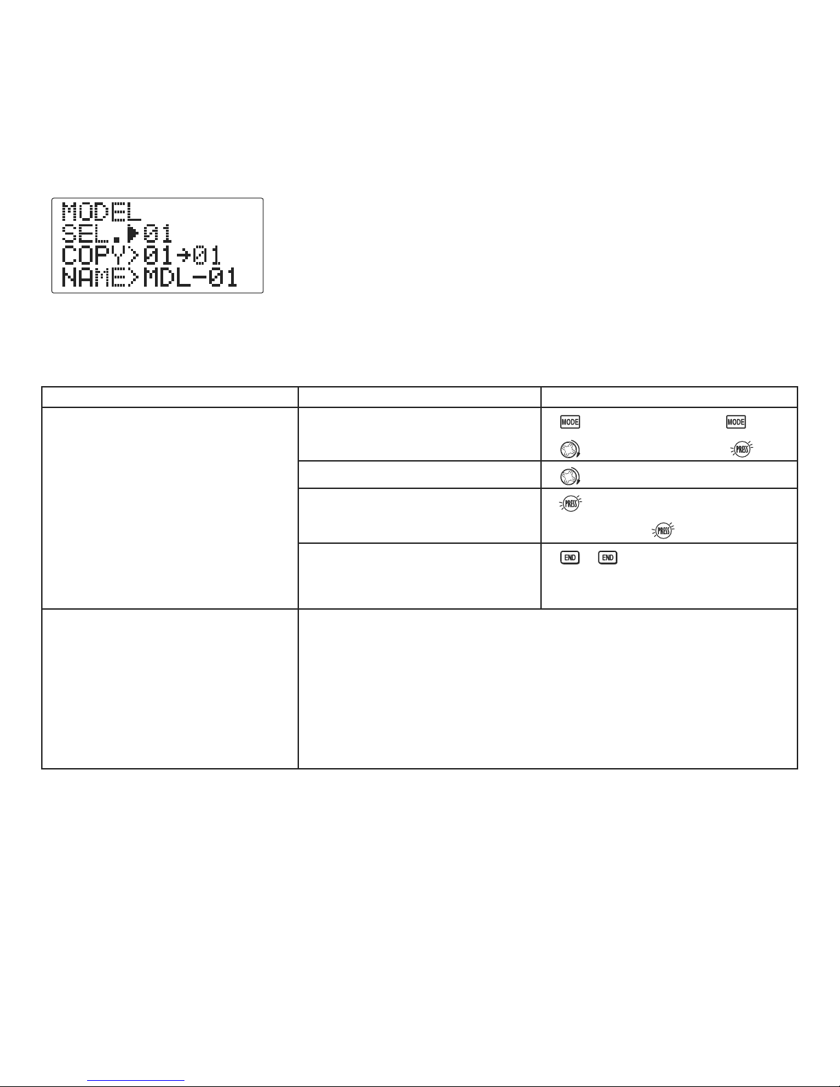
MODEL SELECT: This function selects which of the 10 model memories in the
transmitter to set up or fly.
(Each model memory may be of a different model type from the other memories.)
GOAL: STEPS: INPUTS:
Select Model #3.
Open BASIC menu, then open MODEL
for 1 second.
(If ADVANCE, again.)
submenu.
NOTE: This is one of several functions
for which the radio requires
confirmation to make a change.
Choose Model #3.
Confirm your change.
if required to MODEL.
to 3.
for 1 second.
Where next?
sure? displays.
Close.
NAME the model: see p. 27.
Change MODELTYPE (aircraft, heli): see p. 28.
Utilize servo REVERSE: see p. 30.
Adjust END POINTs: see p. 31.
Set up TH-CUT for throttle management: see p. 32.
25
Page 26
MODEL COPY: copies the current model data into another model memory in the transmitter.
The number of the model memory you are copying from and into is displayed.
Notes:
Any data in the model copied to will be written over and lost, including name and type.
•
It cannot be recovered.
Examples:
Start a new model that is similar to one you have already programmed.
•
Copy the current model data into another model memory as a backup or before experimenting with new settings.
•
Edit a copy of your model’s data to fly the model in different conditions (i.e. Helicopter using heavier weight blades;
•
airplane model at extreme altitudes).
GOAL of EXAMPLE: STEPS: INPUTS:
Copy model 3 into model 5.
NOTE: This is one of several
functions for which the radio requires
confirmation to make a change.
Where next?
*Radio shows progress on screen as the model memory is being copied. Note that if the power switch is turned off prior to completion,
the data will not be copied.
Open the BASIC menu, then open
MODEL submenu.
Confirm you are currently using the
proper model memory. (Ex: 3)
Go to MODEL COPY and choose the
model to copy into. (Ex: 5)
Confirm your change.
Close.
SELECT the copy you just made: see p. 25.
Rename it (it is currently named exactly the same as the model copied): see p. 27.
for 1 second.
to MODEL.
If SELECT does not indicate 3,
use MODEL SELECT, p. 25.
for 1 second.
sure? displays. *
(If ADVANCE, again.)
to 5.
26
Page 27

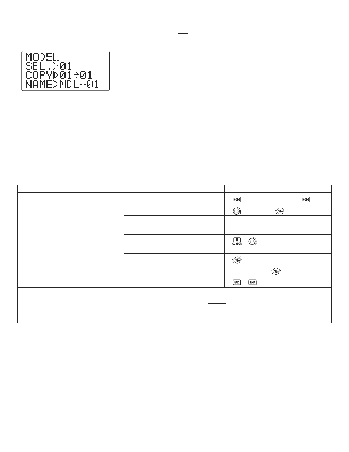
MODEL NAME: assigns a name to the current model memory. By giving each model a name that is immediately
recognizable, you can easily comfirm the correct model, and minimize the chance of flying the wrong model memory which
could lead to a crash.
Adjustability and values:
Up to 6 characters long.
•
Each character may be a letter, number, blank, or a symbol.
•
The default names assigned by the factory are in MDL-xx format (MDL-01 for
•
first model memory, etc.)
NOTE: When you COPY one model memory over another, everything is copied, including the model's name. Similarly, if you
change MODEL TYPE or do a MODEL RESET, the entire memory is reset, including MODEL NAME. So the first thing you will want
to do after you COPY a model, change its type, or start from scratch, is rename the new copy to avoid confusion.
GOAL of EXAMPLE: STEPS: INPUTS:
Name model 3 "CAP-01" (where
the underline represents a blank
space.)
Open MODEL submenu.
Confirm you are currently using the
proper model memory. (Ex: 3)
Go to NAME and change the first
character. (Ex: M to C)
Choose the next character to change.
for 1 second.
to MODEL.
If SELECT does not indicate 3,
perform MODEL SELECT, p. 25.
(If ADVANCE, again.)
to C.
Where next?
Repeat the prior steps to complete
naming the model.
Close.
Change the MODEL TYPE to helicopter: see p. 28.
Utilize servo REVERSE : see p. 30.
Adjust servo travel with END POINT : see p. 31.
Set up dual/triple rates and exponential (D/R,EXP): see p. 33.
to A
Repeat.
27
Page 28

PARAMETER submenu: sets those parameters you would likely set once, and then not disturb again.
Once you have selected the correct model you wish to work with, the next step is
setting up the proper parameters for this specific model:
What is the model's type?
•
Assign the desired SW to CH5 and CH7.
•
First it is important to clear out any old settings in the memory from prior use, using the MODEL RESET.
MODEL RESET: completely resets all data in the individual model you have currently selected. Don't worry - there is no way
you can accidentally delete all models in your radio with this function. Only a service center can completely reset your
radio's entire memory at once. To delete each model in your radio's memory (for example when selling), you must SELECT
each model, reset that memory, then go SELECT the next memory, etc.
Note that when you COPY one model memory into another or change the model's type, you need not delete all existing data
first by using this function. COPY completely overwrites anything in the existing model memory, including MODEL NAME.
The MODEL TYPE function overwrites all data except name.
GOAL of EXAMPLE: STEPS: INPUTS:
Reset model memory 1.
NOTE: This is one of several
functions for which the radio requires
confirmation to make a change.
Where next?
Confirm you are currently using the
proper model memory. (Ex: 1)
Open PARAMETER submenu.
Reset the Memory.
Confirm the change.
Close.
Now that the memory is reset, name has returned to the default (Ex: MDL-01).
NAME the model: p. 27.
COPY a different model into this memory: p. 25.
SELECT a different model to edit or delete: p. 25.
Change the MODEL TYPE to helicopter: see p. 28.
Utilize servo REVERSE: see p. 30.
Adjust servo travel with END POINT: see p. 31.
Set up dual/triple rates and exponential (D/R,EXP): see p. 33.
On home screen, check model name and
number on top left and right. If it is not
correct, use MODEL SELECT, p. 25.
for 1 second.
to 3rd page of menu.
to PARAMETER.
for one second.
sure? displays. *
(If ADVANCE, again.)
*Radio shows progress on screen as the model memory is being reset. Note that if the power switch is turned off prior to completion,
the data will not be reset.
28
Page 29

MODEL TYPE: sets the type of programming used for this model.
The 7C has 10 model memories, which can each support:
One powered aircraft (ACR O) memory type (with multiple wing and tail
•
configurations. See FLAPERON, ELEVON and V-TAIL for further information.);
Six helicopter swashplate types, including CCPM. See Helicopter MODEL TYPE
•
for details, p. 61.
Before doing anything else to set up your aircraft, first you must decide which MODEL TYPE best fits this particular aircraft.
(Each model memory may be set to a different model type.) If your transmitter is a 7CA, the default is ACRO. If it is a 7CH,
the default is H-1.
If you are using a heli
your model setup. Note that changing
GOAL of EXAMPLE: STEPS: INPUTS:
Select the proper MODEL TYPE for your
model. Ex: ACRO.
[NOTE: This is one of several functions
that requires confirmation to make a
change. Only critical changes require
additional keystrokes to accept
the change.]
MODEL TYPE
, please go to that chapter now to select the proper model type and support
MODEL TYPE
Open the BASIC menu, then open the
PARAMETER submenu.
Go to MODEL TYPE.
Select proper MODEL TYPE.
Ex: ACRO.
Confirm the change. Close PARAMETER.
resets all data for the model memory, including its name.
Turn on the transmitter.
for 1 second.
then to highlight PARAMETER.
to choose PARAMETER.
to TYPE.
to ACRO. for 1 second.
sure? displays. to confirm.
to return to BASIC menu.
(If ADVANCE, again.)
29
Page 30

Auxiliary channel function (CH5 and CH7): defines the relationship between the transmitter
controls and the receiver output for channels 5 and 7.
Adjustability:
Channels 5 and 7 may be assigned to any SWITCH (A-H) or none (null).
•
(for example, moving flaps to a switch)
Multiple channels may be assigned to the same switch.
•
Channels set to "NULL" are only controlled by mixes.
•
GOAL of EXAMPLE: STEPS: INPUTS:
Change channel 5 to switch D.
Open BASIC menu then PARAMETER
submenu.
for 1 second.
(If ADVANCE, again.)
to PARAMETER.
Go to channel 5 switch assignment.
Change to D.
Close.
Remember that if you assign primary control of a channel to a switch which you later use for other functions (like
dual/triple rates or airbrakes), every time you use that other function you will also be moving the auxiliary channel.
Servo reversing (REVERSE): changes the direction an individual servo responds to a CONTROL STICK motion.
For CCPM helicopters, be sure to read the section on SWASH AFR (p. 63) before reversing any servos.
Except with CCPM helicopters, always complete your servo reversing prior
other programming. If you use pre-built ACRO functions that control multiple servos,
such as FLAPERON or V-TAIL, it may be confusing to tell whether the servo needs to be
reversed or a setting in the function needs to be reversed. See the instructions for each
specialized function for further details.
Always check servo direction prior to every flight as an additional precaution to confirm proper model memory,
hook ups, and radio function.
to CH5-SW.
to D.
to any
NOTE: THR-REV is a special function that reverses the entire throttle control, including moving the trim functionality to the
Stick's upper half. To use THR-REV, turn off the transmitter, hold down the MODE and END keys, turn on. CURSOR DOWN to
THR-REV and turn the DIAL to REV. Turn the transmitter off and back on. This change affects all models in the radio.
GOAL of EXAMPLE: STEPS: INPUTS:
Reverse the direction of the elevator
servo.
Where next?
Open REVERSE function.
Choose proper channel and set
direction. (Ex: ELE REV)
Close.
Adjust servo travel with END POINT: see p. 31.
Set up dual/triple rates and exponential (D/R,EXP): see p. 33.
Set up flight timers: see p. 36.
Set up trainer functions: see p. 37.
30
for 1 second.
to REVERSE.
to ELE.
to REV.
(If ADVANCE, again.)
Page 31

End Point of servo travel adjustment (E.POINT , also called EPA): The most flexible version of travel adjustment
available. It independently adjusts each end of each individual servo’s travel, rather than one setting for the servo that
affects both directions. Again, for CCPM helicopters, be sure to see SWASH AFR (see p. 63) prior to adjusting end points.
Adjustability:
Can set each direction independently.
•
Ranges from 0% (no servo movement at all) to 140%. At a 100% setting, the throw of
•
the servo is approximately 40° for channels 1-4 and approximately 55° for channels 5-8.
Reducing the percentage settings reduces the total servo throw in that direction.
•
Examples:
Adjust the throttle high end to avoid binding at the carburetor, and low end to allow for proper carburetor closure.
•
Adjust flap so up travel is only sufficient for straight and level flight trimming, with full down travel.
•
END POINT may be adjusted to 0 to keep a servo from moving one direction, such as flaps not intended to also operate
•
as spoilers.
Retract servos are not proportional. Changing END POINT will not adjust the servo.
•
END POINT adjusts only the individual servo. It will have no effect on any other servo that is operated in conjunction with
this servo via mix or preset programming such as FLAPERON , etc. This is so that each individual servo can be
carefully fine-tuned to avoid binding and other conflicts. To adjust the total travel of a function
the adjustments in that function's controls. For CCPM helicopters, adjust the total travel of the function
pitch, in SWASH AFR.
such as FLAPERON, make
, such as collective
Adjust the linkage or the END POINT? It is nearly always best to adjust your linkages to get as close as possible prior to
utilizing END POINT. The higher the END POINT setting, the better position accuracy and the more servo power available at
nearly any position (except if using digital servos). Higher END POINT values also mean longer travel time to reach the
desired position, as you are utilizing more of the servo's total travel. (For example, using 50% END POINT would give you
only half the steps of servo travel, meaning every click of trim has twice the effect and the servo gets there in half the time).
End point (and moving the linkage) = torque, accuracy, but transit time to get there.
•
End point (instead of adjusting linkages) = travel time, but torque, accuracy.
•
GOAL of EXAMPLE: STEPS: INPUTS:
Decrease the flap servo throw in the
upward direction to 5% to allow
trimming of level flight only and down
travel to 85% to prevent binding.
Where next?
Open END POINT function.
Choose proper channel and set
direction. (Ex: flap up 5%)
Close.
Move auxiliary channels 5 or 7 to different switch(es): see p. 28.
Set up THR-CUT to cut the engine: see p. 32.
Set up dual/triple rates and exponential (D/R,EXP): see p. 33.
Set up flight timers: see p. 36.
Set up trainer functions: see p. 37.
Set up twin aileron servos: see p. 42.
for 1 second.
to END POINT.
flap control [default is V
to 5%.*
V
R to 85%.
(If ADVANCE, again.)
to flap.
R ].
*You can reset to the initial values by pressing the DIAL for one second.
31
Page 32

Engine idle management: THR-CUT: Functions which work with the digital THROTTLE TRIM to provide a simple,
consistent means of engine operation. No more fussing with getting trim in just the right spot for landings!
Throttle cut (TH-CUT) (ACRO/HELI): Provides an easy way to stop the engine by flipping a switch (with THROTTLE STICK
at idle). The movement is largest at idle and disappears at high throttle to avoid accidental dead sticks. In HELI, there is an
additional setting, TH-CUT See p. 66.
GOAL of EXAMPLE: STEPS: INPUTS:
Decrease the throttle setting (at idle) to
stop the engine with the flip of a switch.
Open BASIC menu, then open
THR-CUT function.
for 1 second.
(If ADVANCE, again.)
to THR-CUT.
(default: SWITCH A in the down
position)
Activate the function. Choose desired
switch, and the position which
activates the function.
to ON(OFF).
to SW.
to select the desired
switch and position.
With T
HROTTLE STICK at idle, adjust the
A to down position.
rate until the engine consistently shuts
off but throttle linkage is not binding.*
THROTTLE STICK.
to RATE. until shuts off.
Close.
Where next?
Set up dual/triple rates and exponential (D/R,EXP): see p. 33.
Set up TRAINER functions: see p. 37.
Set up twin aileron servos: see p. 42.
*Normally, a setting of 10-20% is sufficient. Viewing the carburetor barrel until it fully closes is adequate to get an approximate setting; then test with
engine running to confirm.
32
Page 33

Dual/triple rates and exponential (D/R,EXP): assigns adjusted rates and exponential.
Dual/Triple Rates: Reduce/increase the servo travel by flipping a switch,
or (AC RO ) they can be engaged by any stick position. Dual rates affect the control
listed, such as aileron, not just a single (ex: channel 1) servo. For example, adjusting
aileron dual rate will affect both aileron servos when using FLAPERON, ELEVON, and
a CCPM helicopter.
Activation:
Any SWITCH, A-H. If you choose a 3-position switch, then that dual rate instantly becomes a triple rate (see example).
•
Stick position (ACRO ). (Ex: On rudder you normally use only the center 3/4 of the stick movement except
•
for extreme maneuvers such as snaps/spins/stalls. As long as your R
throw, the rudder responds at your lower rate, allowing small, gentle corrections. When the stick passes 90% (ie. stall
turn), the rudder goes to high rate's 90%, which is a MUCH higher amount of travel than your low rate at 89%.)
Ex: EPA = 1" Low Rate = 50% High Rate = 100%
At 89% Low Rate = .45"
At 90% High Rate = .9"
UDDER STICK does not exceed 90% of maximum
100% 100%
90% 90%0%
Adjustability:
Range: 0 - 140% (0 setting would deactivate the control completely.)
High Rate
Low Rate
Exponential: Changes the response curve of the servos relative to the stick position to make flying more pleasant. You
can make the servo movement less or more sensitive around neutral for rudder, aileron, elevator, and throttle (except HELI
type - use THROTTLE CURVE instead).
Why use expo? Many models require a large amount of travel to perform their best tricks. However, without exponential,
they are “touchy” around neutral, making them unpleasant to fly and making small corrections very difficult. Additionally,
by setting different exponentials for each rate, you can make the effectiveness of small corrections similar in each rate, as
in our example below.
The best way to understand exponential is to try it:
Having made no changes yet in the D/R,EXP screen, move S
•
Cursor down to EXPand dial to 100%.
•
Move SWITCH D up. Hold the AILERON STICK at 1/4 stick and move SWITCH D down.
•
Notice how much less travel there is.
•
Go to 3/4 stick and repeat. Notice how the travel is much closer, if not identical.
•
High Rate
High RateLow Rate
100%30%0%
•
Initial value=100%
WITCH D to "down" (toward the AILERON STICK
).
33
Page 34

Adjustability:
More sensitive around neutral. (positive exponential, see example)
•
Less sensitive around neutral. (negative exponential, see example)
•
For ACRO throttle, exponential is applied at the low end to help nitro and gasoline engines have a linear throttle response,
so that each 1/4 stick increases engine RPM 25% of the available range. (In most engines this ranges from 5-60%.)
GOAL of EXAMPLE: STEPS: INPUTS:
Set up dual rates and exponential
Open
D/R,EXP.
for 1 second.
(If ADVANCE, again.)
in ACRO mode.
to D/R,EXP.
Choose channel and switch position.
to desired channel.
Set rate (Ex: high rate = 95%)
to 95%.
Set expo (Ex: expo = -15%)
Go to 2
nd
switch position and set rate
to different position.
(Ex: low rate 70%)
nd
Set 2 expo (Ex: expo = -3%)
Optional: if using a 3 position switch,
set 3rdrate.
Close.
GOAL of EXAMPLE: STEPS: INPUTS:
Set up dual rates and exponential in
Open D/R,EXP.
for 1 second.
HELI mode.
to D/R,EXP.
Note: In HELI mode the switch does
not change the rate being adjusted.
Choose channel and switch position.
to desired channel and
switch position.
Change switch channel and switch
position with mode button.
Set rate (Ex: high rate = 95%.)
to 95%.
to -15%.
to 70%.
to -3%.
(If ADVANCE, again.)
Set expo (Ex: expo = -15%)
34
to -15%.
Page 35

GOAL of EXAMPLE: STEPS: INPUTS:
Set up aileron triple rates on SWITCH G
Open D/R,EXP function.
for 1 second.
with travel settings of 75% (normal),
25% (slow roll) and 140% (extreme
aerobatics) and exponential settings of
0%, +15%, and -40% respectively.
Choose the channel to change
(Ex: aileron is already selected)
to D/R,EXP.
Optional: change switch assignment.
NOTE: This normal rate has no
exponential so it has a very linear,
normal feel. This slow roll rate has
Confirm switch is in desired position
and set rate. (Ex: up = high rate, 75%).
G to up position.
positive exponential (the opposite of
what most people normally use),
which makes the servos more
responsive around center. This makes
the servos feel the same around center
Move S
WITCH to 2nd rate position and
set this particular rate.
(Ex: center = low rate, 25%).
G to center position.
in the normal and low rates, but still
gives a very slow roll rate at full stick.
The 3D rate (extreme aerobatics) has a
very high distance of travel B nearly
twice that of the normal rate.
Therefore, using a very high negative
exponential setting softens how the
servos respond around center stick.
This makes the servos respond
similarly around center stick for a
more comfortable feel.
Optional: if using a 3 position
SWITCH, move SWITCH to 3rd position
and set this rate (Ex: down = 3D rate,
140%).
Optional: instead of using a switch,
you can set high rates to be triggered
when the stick moves past a certain
point. To test this, set aileron high
rate to 25%.
AILERON STICK
Move
to the right
G to down position.
and notice the huge jump in travel
Many modelers like to set up all 3
triple rates on a single 3-position
switch, creating a "slow and pretty
mode", a "normal mode", and a "wild
after the stick moves 90% of its
distance.
You may also change the trigger point
by holding the stick at the desired point,
then pressing and holding the
stunts mode" all with the flip of a
single switch. To do so, simply set up
rates for all 3 controls and assign all 3
to the same 3-position switch.
Set each rate's EXP.
(Ex: 0%, +15%, -40%)
G to up position.
confirm EXP reads 0.
(If ADVANCE, again.)
to desired channel.
to G.
to 75%
to 25%
to 140%
to 1.
to 25%
DIAL.
Where next?
G to down position.
to 15%
G to center position.
to -40%
Repeat above steps for elevator and rudder.
Close.
Set up flight timers: see p. 36.
Set up TRAINER functions: see p. 37.
Adjust the sensitivity of the trims: see p. 38.
Set up twin aileron servos: see p. 42.
Set up programmable mixes to meet your specific needs: see p. 53.
35
Page 36

TIMER submenu (stopwatch functions): controls an electronic clock used to keep track of allowed time remaining in a competition,
flying time on a tank of fuel, amount of time on a battery, etc.
Adjustability:
Count down timer: starts from the chosen time, displays time remaining. If the time is exceeded, it continues to count
•
below 0.
Count up timer: starts at 0 and displays the elapsed time up to 99 minutes 59 seconds.
•
Independent to each model, and automatically updates with model change.
•
In either TIMER mode, the timer beeps once each minute. During the last twenty seconds, there's a beep each two seconds.
•
During the last ten seconds, there's a beep each second. A long tone is emitted when the time selected is reached.
To Reset, choose the desired timer with the SELECT key (while at the startup screen), then press and hold DIAL for 1 second.
•
Activation by either direction of
•
fuel remaining, or for an electric, how much battery is left.
To quickly reset any timer from the home screen, cursor down until the timer blinks. Press dial to reset.
•
GOAL of EXAMPLE: STEPS: INPUTS:
Set timer to count down 4-1/2
minutes, being controlled by
THROTTLE STICK position. This is
utilized to keep track of actual
Throttle on time to better correlate
with fuel/battery usage.
WITCH A-H, by STICK (1-4) . THROTTLE STICK is convenient if you are keeping track of
S
Open BASIC menu, then
open TIMER function.
Activate the function.
Adjust time to 4 min. 30 sec., count down.
Assign to T
trigger point (if timer is to trigger
BELOW this throttle point, so
arrow points down).
HROTTLE STICK and set
for 1 second.
to page 3.
to TIMER.
to 4. to 30.
to SW.
to 3(arrow points up).
HROTTLE STICK to desired
T
position (Ex: 1/4 stick).
(If ADVANCE, again.)
Where next?
for 1 second to set.
Close.
Adjust END POINTs after first flight test: see p. 31.
Adjust auxiliary channel assignments: see p. 28.
Set up TRAINER functions: see p. 37.
36
Page 37

TRAINER: For training novice pilots with optional trainer cord connecting 2 transmitters. The instructor has several levels
of controllability.
Adjustability:
"N": When the TRAINERSWITCHis ON, the channel set to this mode can be
•
controlled by the student. The set channel is controlled according to any
programming set in the student's transmitter.
"F": When the TRAINERSWITCHis ON, the channel set to this mode can be controlled
•
by the student, controlled according to any mixing set in the instructor's transmitter.
"-": The channel set to this mode cannot be controlled by the student even when the TRAINER SWITCH is ON. The set
•
channel is controlled by the instructor only, even when the T
SWITCH: controlled by spring-loaded SWITCH F (7CA) or H (7CH) only. Not assignable.
•
Compatibility: The 7C may be master or student with any Futaba FM transmitter compatible with the cord. Simply
•
plug the optional trainer cord (For 7C series, sold separately) into the trainer connection on each transmitter, and
follow the guidelines below.
Examples:
When throttle/collective are set to "F", 5-channel helicopter practice is possible with a 4-channel transmitter.
•
Set up the model in a second transmitter, use "N" mode to quickly and safely check proper operation of all
•
functions, then allow the student radio to fully fly the model.
Using "N" mode, set lower throws, different exponentials, even different auxiliary channel settings on the student
•
radio (if it has these features).
To ease the learning curve, elevator and aileron may be set to the "N" or "F" mode, with the other channels set to
•
"-" and controlled by the instructor.
RAINER SWITCH is ON.
Precautions:
NEVER turn on the student transmitter power.
•
ALWAYS set the student transmitter modulation mode to PPM. (If using conventional system.)
•
BE SURE that the student and instructor transmitters have identical trim settings and control motions. Verify by
•
switching back and forth while moving the control sticks.
FULLY extend the instructor's antenna. Collapse the student's antenna. (If using conventional system.)
•
Always remove the student transmitter's RF module. (If using conventional system.)
•
When the TRAINER function is active, the snap roll function is deactivated. Other functions, such as THR-CUT,
•
which have been assigned to the same switch, are not deactivated. Always double check your function assignments
prior to utilizing the TRAINER function.
When you select a different model, the TRAINER function is deactivated in the current model for safety reasons.
•
GOAL of EXAMPLE: STEPS: INPUTS:
Turn on the TRAINER system and set
up so student has: fully functional
control of aileron to
FLAPERON ;
normal control of rudder to allow
lowered travel; and no throttle
channel control (with the instructor
for safety).
support
Open BASIC menu, then open
TRAINER function.
Activate TRAINER.
Choose desired channel(s) and proper
training type(s).
Close.
for 1 second.
to page 3. to TRAINER.
to OFF.
past AIL and ELE(default OK).
to THR,
to RUD,
(If ADVANCE, again.)
to "-": OFF.
to "N": NORM.
Where next?
TEST student radio function fully prior to attempting to fly!
Set up dual/triple rates and exponential (D/R,EXP) on student 7C: see p. 33.
Reset trims on student 7C: see p. 38.
37
Page 38

TRIM submenu: Resets and adjusts effectiveness of digital trims.
The 7C has digital trims which are different from conventional mechanical trim sliders.
Each T
RIM LEVER is actually a two-direction switch. Each time the TRIM LEVER is
pressed, the trim is changed a selected amount. When you hold the T
speed increases. The current trim position is graphically displayed on the start up screen.
The TRIM submenu includes two functions that are used to manage the trim options.
RIM LEVER, the trim
HELI models only: OFFSET is available in the idle ups. If OFFSET is inhibited, adjustment of the T
RIM LEVERS will adjust the
trims for all flight conditions. If OFFSET is active, then moving the trims within any one condition will affect only that
condition. See OFFSET, p. 70.
Trim reset (CLR): Electronically centers the trims to their default values. Note that the SUB-TRIM settings and the trim
STEP rate are not reset by this command.
GOAL of EXAMPLE: STEPS: INPUTS:
Reset trims to neutral after having
adjusted all linkages.
Open BASIC menu, then open
TRIM submenu.
for 1 second.
(If ADVANCE, again.)
to TRIM.
NOTE: This is one of several
Request and confirm the reset.
for 1 second.
functions for which the radio requires
.
confirmation to make a change.
Beep sounds.
Close.
Where next?
Adjust SUB-TRIMs: see p. 39.
Adjust trim rate (STEP): see below.
Adjust END POINTs: see p. 31.
Set up dual/triple rates and exponential (D/R,EXP): see p. 33.
Trim step: Changes the rate at which the trim moves when the TRIM LEVER is activated. It may be set from 1 to 40
units, depending on the characteristics of the aircraft. Most ordinary aircraft do well at about 2 to 10 units. Generally larger
trim steps are for models with large control throws or for first flights to ensure sufficient trim to properly correct the model.
Smaller trim steps are later used to allow very fine adjustments in flight.
GOAL of EXAMPLE: STEPS: INPUTS:
Double the sensitivity (larger step) of
the AILERON TRIM LEVERS for a first
flight of an aerobatic model to ensure
sufficient range to trim the model for
level flight.
Where next?
Open
TRIM submenu.
for 1 second.
to TRIM.
Choose the STEP you wish to change.
to CH1.
(Ex: aileron)
Adjust the size of the step. (Ex: incr. to 8)
Repeat as desired for other channels.
to 8.
to ELEV. to new setting.
Repeat as needed.
Close.
Adjust sub trims: see p. 39.
Adjust END POINTs: see p. 31.
Set up dual/triple rates and exponential (D/R,EXP): see p. 33.
38
(If ADVANCE, again.)
Page 39

SUB-TRIM: Makes small changes or corrections to the neutral position of each servo. Range is -120 to +120, with 0 setting,
the default, being no SUB-TRIM.
We recommend that you center the digital trims before making SUB-TRIM
changes, and that you try to keep all of the SUB-TRIM values as small as
possible. Otherwise, when the SUB-TRIMs are large values, the servo's
range of travel is restricted on one side.
The recommended procedure is as follows:
Measure and record the desired surface position;
•
Zero out both the trims (TRIM RESET menu) and the SUB-TRIMs (this menu);
•
Mount servo arms and linkages so that the control surface's neutral is as correct as possible; and
•
Use a small amount of SUB-TRIM to make fine corrections.
•
GOAL of EXAMPLE: STEPS: INPUTS:
Adjust the flap servo's SUB-TRIM until
its center exactly matches the aileron
servo's center, as they will work
together as flaperons.
Open BASIC menu, then open
SUB-TRIM.
Choose the channel to adjust, and
adjust until surfaces match. (Ex: flap)
Repeat for other channels.
Close.
for 1 second.
as needed. to each channel,
as needed.
(If ADVANCE, again.)
to SUB-TRIM.
Where next?
Adjust trim steps: see p. 38.
Adjust END POINTs: see p. 31.
Set up dual/triple rates and exponential (D/R,EXP): see p. 33.
39
Page 40

FailSafe (loss of clean signal and low receiver battery) submenu (F/S): Sets responses in case of loss of signal or low Rx
battery .
FailSafe (F/S ): instructs a receiver what to do in the event radio interference is received.
Adjustability:
Only channel 3(throttle) may be set.
•
The NOR (normal) setting holds the servo in its last commanded position.
•
The F/S (FailSafe) function moves servo to a predetermined position.
•
NOTE: the setting of F/S also applies to the Battery F/S(see below).
•
Examples:
Set the throttle channel so that the engine idles when there is interference (ACRO). This may give enough time to fly away
•
from and recover from the radio interference and minimize damage if crashed.
For helicopters, NOR is typically the safest choice.
•
Updating F/S Settings: If you specify a F/S setting, the FailSafe data is automatically transmitted always.
When you choose the F/S mode, check that your settings are as desired by turning off the transmitter power switch and
verifying that the servos move to the settings that you chose.
GOAL of EXAMPLE: STEPS: INPUTS:
Change the receiver FailSafe command
for channel 3 to a preset position.
Open the BASIC menu, then open
F/S function.
for 1 second.
to F/S .
(If ADVANCE, again.)
NOTE: This is one of several functions
for which the radio requires
confirmation to make a change.
Where next?
Battery FailSafe (F/S ): A second battery low warning feature (built into the 2.4GHz receiver).
When the airborne battery voltage drops below approximately 3.8V, the receiver’s battery F/S function moves the throttle to a
predetermined position. When the Battery F/S function is activated, your engine will move to idle (if you haven't set
a position) or a preset position. You should immediately land. You may temporarily reset the Battery F/S function by
moving the THROTTLE STICK to idle. You will have about 30 seconds of throttle control before the battery function
reactivates.
Set and confirm fail safe command.
Close.
Wait two minutes and confirm F/S settings as described above.
Read below for information on Battery FailSafe.
Adjust END POINTs to gain proper F/S responses if needed: see p. 31.
Adjust SUB-TRIM to gain proper F/S responses if needed: see p. 39.
throttle stick to desired position
(idle position: ACRO)
to F/S .
for 1 second to store.
Adjustability:
NOR F/S setting for throttle results in Battery F/S going to the servo position reached by moving THROTTLE STICK to the
•
bottom with T
POS F/S setting for throttle results in Battery F/S also going to the same throttle servo position as the regular F/S .
•
If using a 6V (5-cell) receiver battery, it is very likely that your battery will be rapidly running out of charge before
battery FailSafe takes over. It is not a good idea to count on battery Fail Safe to protect your model at any time, but
especially when using a 5-cell battery.
RIM LEVER centered;
40
Page 41

ACRO ADVANCE MENU FUNCTIONS:
Aircraft wing types (ACRO):
There are 3 basic wing types in aircraft models:
v Simple. Model uses one aileron servo (or multiple servos on a Y-harness into a single receiver channel) and has a tail.
This is the default setup and requires no specialized wing programming.
v Twin Aileron Servos. Model uses 2 aileron servos and has a tail. see Twin Aileron Servos.
v Tail-less model (flying wing). Model uses 2 wing servos working together to create both roll and pitch control.
see ELEVON.
Twin Aileron Servos (with a tail) (ACR O): Many current generation models use two aileron servos, plugged into two
separate receiver channels. (If your model is a flying wing without separate elevators, see ELEVON, p. 44.)
Benefits:
v Ability to adjust each servo's center and end points for perfectly matched travel.
v Redundancy, for example in case of a servo failure or mid-air collision.
v Ease of assembly and more torque per surface by not requiring torque rods for a single servo to drive 2 surfaces.
v Having more up aileron travel than down travel for straighter rolls – aileron differential. (see glossary for definition.)
v Using the two ailerons not only as ailerons but also as flaps, in which case they are called flaperons.
Options:
v 5-channel receiver. Set up AIL-2 (see p. 42) in FLAPERON.
v FLAPERON:
v Uses CH6 for the second servo (see AIL-2 to use CH5 orCH7.)
v Allows flap action as well as aileron action from the ailerons.
v Provides FLAP-TRIM function to adjust the neutral point of the flaperons for level flight.
v Also allows aileron di
fferential in its own programming.
Channel 6 = normal flaperons, 2 servos operate together as flaps;
Channel 5 or 7 = act like aileron differential did in prior radios; channel 6 is still FLAPS, and the 2 ailerons
never act together as flaps EXCEPT in the airbrake function.
NOTE: Only one of the two wing-type functions (FLAPERON and ELEVON) can be used at a time. Both functions
cannot be activated simultaneously. To activate a different wing type, the first must be inhibited.
GOAL of EXAMPLE: STEPS: INPUTS:
De-activate FLAPERON so that
Open the FLAPERON function.
for 1 second.
(If basic, again.)
ELEVON can be activated.
to FLAPERON.
Inhibit the function.
to INH.
Close function.
Where next?
Set up ELEVON (see p. 44).
41
Page 42

Using FLAPERON (ACRO):
The FLAPERON mixing function uses one servo on each of the two ailerons, and uses them
for both aileron and flap function. For flap effect, the ailerons raise/lower simultaneously.
Of course, aileron function (moving in opposite directions) is also performed.
Once FLAPERON is activated, any time you program CH6 or "Flap" (ie. FLAP-ELEVATOR mixing), the radio commands both
servos to operate as flaps. A trimming
feature is also available (see
FLAP-TRIM) to adjust both neutral positions together
for straight-and-level flight or slight increases/decreases of the flap angle.
END POINT and SUB-TRIM both still adjust each servo individually.
Second aileron servo (AIL-2): The default for the second aileron servo is CH6 and this allows both servos to work
as ailerons and flaps. If CH5 or CH7 is selected the flap function only works CH6, and the two aileron servos
function only as ailerons except in the air brake (A. BRAKE) function. In the air brake function the flap servo CH6
and the aileron servos CH1 and (CH5 or CH7) work together.
GOAL of EXAMPLE: STEPS: INPUTS:
Activate twin aileron servos, FLAPERON.
Input 10% more up travel than down
travel (aileron differential) within the
FLAPERON programming.
Open the FLAPERON function.
Activate the function.
Optional: adjust the aileron
for 1 second.
to FLAPERON.
to +10%.
(If basic, again.)
*
differential.(Ex: +10%)
Optional: If using a 5 channel
receiver, change AIL-2 from CH6
to CH5.
Close menu.
Where next?
Set FLAP-TRIM: see p. 43.
Set up AIRBRAKE mix: see p. 52.
View additional model setups on the internet: www.futaba-rc.com/faq/faq-7c.html
*If the FLAPERON function does not activate there is a conflicting mix activated such as ELEVON.
to CH5.
42
Page 43

FLAP-TRIM allows the flap action to be set in a way that it can be adjusted with the VR
dial. AIRBRAKE will also move the flaps to a specified position via movement of a switch.
The flaps can also be moved with switch using a programmable mix. See offset as master
p.53.
Add FLAP-TRIM to allow the model's
Open FLAP-TRIM.
for 1 second.
(If basic, again.)
ailerons to drop 30% together as flaps
to
from the VR dial.
FLAP-TRIM.
The function is automatically activated with the FLAPERON.
The FLAPERON function must be
active with the second servo set to CH6.
Set the dial to desired zero flap side.
full left.
Set the OFS so that the flap will work
for the full range of the dial.
Set the dial to desired full flap side.
full right.
Set flap throw (Ex 30%).
to 30%.
Close menu.
*If the FLAP-TRIM is inhibited the flap control defaults to the VR dial. You can use E.POINT to set the travel of the flap if you are using one flap servo.
If you are using flaperons with CH1 and CH6 DO NOT inhibit FLAP-TRIM.
43
Page 44

There are 4 basic tail types in aircraft models:
• Simple. Model uses one elevator servo and one rudder servo (or multiple servos on a Y-harness). This is the default.
• Dual Elevator servos. Model uses 2 elevator servos, see AILVATO R(ACRO.) see p. 45.
• Tail-less model. Model uses 2 wing servos together to create roll and pitch control. see ELEVON. see p. 44.
• V-TAIL. Model uses 2 surfaces, at an angle, together to create yaw and pitch control. see V-TAIL . see p. 46.
Note
: Only one of the three tail-type functions (AILVATOR, V-TAIL, and ELEVON) can be used at a time.
(See the wing type example on page 41.)
Using ELEVON(ACRO ): Used with delta wings, flying wings, and other tailless aircraft that combine aileron and
elevator functions, using two servos, one on each elevon. The aileron/elevator travel can be adjusted independently.
This is also popular for ground model use, such as tanks, which drive two motors together for forward, and one motor
forward/one backward for turning. Also aileron differential can be adjusted in this programming.
Adjustability:
• Requires use of CH1 and CH2.
• Independently adjustable aileron/elevator travel.
• Adjustable aileron differential.
NOTE: If ELEVON is active, you cannot activate FLAPERON or AILVATOR. You must inhibit the last function to activate
ELEVON.
NOTE:
Be sure to move the elevator and aileron sticks to full deflection during setup. If a large amount of travel is specified,
when the AILERON and ELEVATOR STICKS are moved at the same time the controls may bind.
(For details on setting up a complex aerobatic plane, such as "space shuttle" style controls, please visit
www.futaba-rc.com\faq\faq-7c.html. Many other setup examples are also available at this location.)
GOAL of EXAMPLE: STEPS: INPUTS:
Activate ELEVON.
Adjust aileron differential to +10%.
Open the ELEVON function.
for 1 second.
to ELEVON.
(If basic, again.)
Activate the function.
Optional: adjust the aileron
to +10%.
differential.
(Ex: +10%. )
Optional: adjust the aileron/elevator
(Elevator travel)
travel as desired.
(Aileron travel)
Where next?
Close menu.
Adjust individual servo's SUB-TRIMs: see p. 39 and END POINTs: see p. 31.
Set up dual/triple rates and exponential (D/R,EXP) : see p. 33.
View additional model setups on the internet: www.futaba-rc.com\faq\faq-7c.html
44
Page 45

Dual Elevator Servos (with a rudder) (AILEVATOR)(ACRO): Many models use two elevator servos, plugged in separate
receiver channels. (Flying wings without a separate aileron control use ELEVON. V-shaped tail models use V-TAIL, p. 51.
Benefits:
• Ability to adjust each servo's center and end points for perfectly matched travel.
• Ease of assembly, not requiring torque rods for a single servo to drive 2 surfaces.
• Elevators acting also as ailerons for extreme stunt flying or more realistic jet
flying (optional).
• Redundancy, for example in case of a servo failure or mid-air collision.
Adjustability:
v Direction of each servo 's travel may be reversed in REVERSE or the set percentages may be reversed here.
v Elevator travels independently adjustable (both directions and percent).
v Optional action as ailerons (defaults to 50% response). This response cannot be activated/deactivated in flight.
Setting AIL3 and 4 to 0 disables this feature. Note: if you want this, but on/off with a switch, set AIL3 and 4 to 0 here, and use
2mixes– AIL-to-ELEV and AIL-to-AUX2(assign a switch) – to get aileron action from the elevator servos when the assigned
switch is on.
The AILEVATOR mixing function uses one servo on each of the two elevators, and combines the elevator function with the
aileron function (unless aileron travel is set to 0). For aileron effect, the elevators are raised and lowered opposite of one
another in conjunction with the ailerons.
Once AILEVATOR is activated, unless you zero out the aileron figures (see below), any time you move your ailerons or any
programming moves your ailerons (ie. RUDDER-AILERON mixing), the radio automatically commands both elevator servos
to also operate as ailerons. To deactivate this action, simply set the 2 aileron travel settings to 0 in the AILEVATOR function.
This way the elevators will work only as elevators.
If using the elevators as ailerons as well, be sure to move the elevator/aileron stick while checking the servo motions. If a
large amount of travel is specified, when the sticks are moved at the same time, the controls may bind.)
OG
Activate twin elevator servos.
Open the AILEVATORfunction.
:STUPNI:SPETS:ELPMAXEfoLA
for 1 second.
(If basic, again.)
Deactivate the elevator-acting-asailerons portion of this function.
to AILEVATOR.
Activate the function.
Note: Depending upon your model's
geometry, you may need to reverse one
servo or set a negative percentage here.
Optional: adjust up/down travel
when operating as ailerons. (Ex: 0.)
Optional: adjust total elevator travel
to 0%.
to 0%.
to 98%.
of each servo. (Ex: right servo
elevator travel to 98%, left to 96%.)
to 96%.
Close menu.
Where next?
Adjust individual servo's SUB-TRIMs: see p. 41 and END POINTs: see p. 31.
Set up Twin Aileron Servos: see p. 43.
Set up AIRBRAKE mix: see p. 52.
45
Page 46

Using V-TAIL(ACRO):
V-TAIL mixing is used with v-tail aircraft so that both elevator and rudder functions
are combined for the two tail surfaces. The elevator and rudder travel can be
adjusted independently.
NOTE: If V-TAIL is active, you cannot activate AILEVATOR or ELEVON functions. See the wing example on page 41.
NOTE:
Be sure to move the elevator and rudder sticks regularly while checking the servo motions. If a large amount of travel
is specified, when the sticks are moved at the same time, the controls may bind. Decrease the travel until no binding occurs.
Adjustability:
• Independently adjustable elevator/rudder travels.
CH (2/1 CH): This allows you to utilize V-TAIL function with v-tail aircraft so that elevator and aileron are combined.
Ex: A v-tail polyhedral wing with no ailerons would use this option. The v-tail will have both pitch and roll on the right
stick.
(For details on setting up a complex plane, such as one with a v-tail AND a separate steerable nosewheel, please visit our
FAQ at www.futaba-rc.com\faq\faq-7c.html. Many other setup examples are also available at this location.)
GOAL of EXAMPLE: STEPS: INPUTS:
Activate V-TAIL.
Adjust the elevator/rudder travels
as desired.
Open the V-TAIL function.
Activate the function.
for 1 second.
to V-TAIL.
(If basic, again.)
Where next?
optional: adjust the travels separately
(Elevator travel)
as desired.
(Rudder travel)
optional: change the channel from
to 2/1CH.
4 to 1. (If needed.)
Close menu.
Adjust END POINTs: see p. 31 and SUB-TRIMs: see p. 39.
Set up dual/triple rates and exponential (D/R,EXP) : see p. 33.
Set up ELEV-FLAP mix: see p. 49.
View additional model setups on the internet: www.futaba-rc.com\faq\faq-7c.html.
46
Page 47

Snap Rolls at the flick of a switch (SNAP-ROLL) (ACRO):
This function allows you to execute snap rolls by flipping a switch, providing the
same input every time. It also removes the need to change dual rates on the 3
channels prior to performing a snap, as SNAP-ROLL always takes the servos to the
same position, regardless of dual rates, inputs held during the snap, etc.
Note: Every aircraft snaps differently due to its C.G., control throws, etc.
Some models snap without aileron; others snap on elevator alone. Most models snap
most precisely with a combination of all 3 surfaces. Additionally , rate of speed and
acceleration when using the snap switch will affect how the model snaps. For
information on using gyros with airplanes for cleaner precision maneuvers, such as
snaps and spins without over rotation, see p. 56.
Adjustability:
• Travel: Adjust the amount and direction of elevator , aileron and rudder travel.
• Range: -120 to +120 on all 3 channels. Default is 100% of range of all 3 channels.
• Directions: (up/right, down/right, up/left, down/left).
This snap-roll function is fully adjustable regarding travels and direction on each of the 3 channels.
AIL ELE RUD
Right positive(up) + + +
Right negative(down) + - Left positive(up) - + Left negative(down) - - +
Note:Always deactivate the TRAINER function prior to activating SNAP-ROLL function.
GOAL of EXAMPLE: STEPS: INPUTS:
Activate SNAP-ROLL. Adjust elevator
Open the SNAP-ROLL function.
travel to 55%, rudder travel to 120% in
the right/up snap.
Activate the function.
Adjust the travels as needed. (Ex:
elevator to +55%, rudder to +120%.)
Where next?
Close menu.
Set up programmable mixes: see p. 53.
View additional setups on the internet: www.futaba-rc.com\faq\faq-7c.html.
for 1 second.
to SNAP-ROLL.
to OFFor ON.
to +55%.
to +120%.
(If basic, again.)
47
Page 48

MIXES: the backbone of nearly every function
Mixes are special programs within the radio that command one or more channels to act together with input from only one
source, such as a stick, switch or knob.
There are a variety of types of mixes.
Types:
• Linear: Most mixes are linear. A 100% linear mix tells the slave servo to do exactly what the master servo is doing,
using 100% of the slave channel's range to do so. An example is FLAPERON. When aileron stick is moved, the flap
servo is told to move exactly the same amount. A 50% linear mix would tell the slave servo, for example, to move to
50% of its range when the master' s control is moved 100%.
• Offset: An OFFSET mix is a special type of linear mix. When the mix is turned on (usually a flip of a switch), the slave
servo is moved a set percent of its range. An example of this is AIRBRAKE --- moving flaps, flaperons, and elevator all
to a set position at the flip of a switch. (see p. 52.)
Essentially every feature in the radio's programming is really a mix, with all assignments/programming set up and ready
to use. Additionally, the7C ACRO and HELI programs provide 3 linear fully-programmable mixes that allow you to
set up special mixes to resolve flight difficulties, activate additional functions, etc.
Let's look quickly at a few examples that are features we've already covered. This may help to clarify the mix types and
the importance of mixes.
Additional examples:
• Exponential is a preprogrammed curve mix that makes the servos’ response more (+) or less (-) sensitive around center
stick (works in conjunction with dual rate, a linear mix that adjusts the total range). see D/R,EXP, p. 33.
• THR-CUT is an OFFSET pre-programmed mix. This tells the throttle servo, when below a certain point, to move toward
idle an additional set percentage to help close the carburetor. See p. 32.
• ELEV-TO-FLAP mixing is a pre-programmed linear mix to move the flaps proportionally to elevator control, helping the
model loop even tighter than it can on elevator alone. (see p. 49.)
Next, we'll get an in-depth look at some pre-programmed mixes (mixes whose channels are predefined by Futaba for
simplicity) we've not covered yet, and last, look at the fully-programmable mix types.
48
Page 49

ELEV-FLAP mixing (ACRO):
ELEV-FLAP mixing is the first pre-programmed mix we'll cover. This mix makes the
flaps drop or rise whenever the ELEVATOR STICK is moved. It is most commonly used
to make tighter pylon turns or squarer corners in maneuvers. In most cases, the flaps
droop (are lowered) when up elevator is commanded.
Adjustability:
• Rate: -100% (full up flap) to +100 (full down flap), with a default of +50% (one-half of the flap range is achieved
when the ELEVATOR STICK is pulled to provide full up elevator.)
• Switch: assignable, or null (mix is always active.)
GOAL of EXAMPLE: STEPS: INPUTS:
Activate ELEV-FLAP mixing. Adjust
Open the ELEV-FLAP function.
for 1 second.
flap travel to 45% flaps.
Activate the function.
Adjust the travels as needed.
(Ex: +45%)
Set switch assignment to null so the
mix is always active.
Optional: change SWITCH control. Ex:
change to NULL so flaps only respond
to ELEVATOR STICK input.
to NULL. (--)
Close menu.
Where next?
Adjust flaperons' flap travel available ( FLAPERON): see p. 42.
Set up AIRBRAKE: see p. 52.
Set up programmable mixes (ex: FLAP-ELEVATOR): see p. 50.
View additional setups on the internet: www.futaba-rc.com\faq\faq-7c.html.
(If basic, again.)
to ELEV-FLAP.
to 45%.
49
Page 50

FLAP-ELEVmixing (ACR O ):
FLAP-ELEV mixing is a pre-programmed linear mix. This mix makes the elevator
move whenever the flaps are moved. This mix is used to compensate for any
pitching created by the flap.
Adjustability:
• Rate: -100% (full up elevator) to +100 (full down elevator), with a default of +50% (one-half of the elevator range is
achieved when the flaps are lowered to full range.)
• Offset: offsets the elevator's center relative to the flaps.
GOAL of EXAMPLE: STEPS: INPUTS:
Activate FLAP-ELEV mixing. Adjust
elevator travel to 45%.
Where next?
Open the FLAP-ELEV function.
Activate the function.
Adjust the travels as needed.
(Ex: +45%)
Close menu.
for 1 second.
(If basic, again.)
to FLAP-ELEV.
to 45%.
View additional setups on the internet: www.futaba-rc.com\faq\faq-7c.html.
to ON.
50
Page 51

AILE-RUDD mixing (ACRO):
Adjustability:
AILE-RUDD mixing is a pre-programmed linear mix. This mix is used to mix
rudder operation with aileron operation automatically, to make realistic
coordinated turns. It is especially effective when turning and banking scale
models or large models that resemble full-sized aircraft.
• Rate: -100% to +100, with a default of +50% (one-half of the rudder range is achieved when the A
pulled to provide full left or right aileron.)
GOAL of EXAMPLE: STEPS: INPUTS:
Activate AILE-RUDD mixing. Adjust
Open the AILE-RUDD function.
for 1 second.
rudder travel to 45%.
to AILE-RUDD.
Activate the function.
Adjust the travels as needed.
(Ex: +45%)
to 45%.
Close menu.
Where next?
View additional setups on the internet: www.futaba-rc.com\faq\faq-7c.html.
ILERON STICK is
(If basic, again.)
51
Page 52

AIRBRAKE mixing(ACRO):
Like FLAPERON, AIRBRAKE is one function that is really made up of a series of pre-programmed mixes all done for you
within the radio. AIRBRAKE simultaneously moves the flap and elevator, and is usually used to make steep descents or
to limit increases in airspeed in dives.
This function is often used even on models without flaps as an easy way to use the flaperons.
Adjustability:
• Activation: Set positions by flipping S
WITCH G.
Provides AIRBRAKE response immediately upon switch movement, going to a pre-set travel on each active channel
without means of in-flight adjustment.
Channels controlled: Elevator and flap may be set independently in AIRBRAKE , including set to 0 to have no effect.
Note: If using FLAPERON with channel 5 or 7 the AIRBRAKE has separate settings for the aileron servos working
as flaperons and the flap.
GOAL of EXAMPLE: STEPS: INPUTS:
Activate AIRBRAKE on a FLAPERON
model. Adjust the flap travel to 50%,
with negative elevator (push) of 10%.
Confirm FLAPERON is active.
Open the AIRBRAKEfunction.
see FLAPERON instructions.
for 1 second.
(If basic, again.)
to AIRBRAKE.
Activate the function.
Switch G in up position.
to OFF.
Adjust the travels as needed. (Ex:
Flap 50%, Elevator -10%.)
to -10%.
to 50%.
Close menu.
Where next?
Adjust flaperons' total flap travel available ( FLAPERON): see p. 42.
Set up ELEV-FLAP mixing: see p. 49.
View additional model setups on the internet: www.futaba-rc.com\faq\faq-7c.html.
52
Page 53

PROGRAMMABLE MIXES (PROG.MIX1-3):
Your 7C contains three separate linear programmable mixes.
There are a variety of reasons you might want to use these mixes. A few are listed here.
Sample reasons to use linear programmable mixes:
•
To correct bad tendencies of the aircraft (such as rolling in response to rudder input).
To automatically correct for a particular action (such as lowering elevator when flaps are lowered).
•
To operate a second channel in response to movement in a first channel (such as increasing the amount of smoke oil
•
in response to more throttle application, but only when the smoke switch is active).
To turn off response of a primary control in certain circumstances (such as simulating one engine flaming-out on a
•
twin, or throttle-assisted rudder turns, also with a twin).
Adjustability:
Defaults : The 3 programmable mixes default to aileron to rudder mixes.
•
• PROG.MIX1-3 aileron-to-rudder for coordinated turns
• Channels available to mix: All three mixes may be changed to use any combination of CH1-7.
Offset may also be set to the master channels. (see below.)
• Master: The controlling channel. The channel whose movement is followed by the slave channel.
• Another channel: Most mixes follow a control channel. (Ex: rudder-to-ailerons, 25%, no switch, corrects roll coupling.)
MASTER SLAVE SWITCH & POSITION RATE OFFSET
RUDD AILE NULL (--) 25% center(default)
• Offset as master: To create an OFFSETmix, set the master as OFST. (Ex: move flap 20% of their total
throw when S
WITCH A is in down position.)
MASTER SLAVE SWITCH & POSITION RATE
OFST CH6 A DOWN 20%
53
Page 54

• Slave: The controlled channel. The channel that is moved automatically in response to the movement of the master
channel. The second channel in a mix’s name (i.e. aileron-to-rudder).
• On/off choices:
• S
WITCH: Any of the positions of any of the 5 switches may be used to activate a mix. Up&Cntr, Cntr&Dn options
allow the mix to be ON in 2 of the 3 positions of a 3-position SWITCH.
• NULL (--): No SWITCH can turn this mix OFF. This mix is active at all times.
• Rate: the percentage of the slave
's range it will move upon maximum input from the master channel. Ex: RUDDER-
AILERON mix, 50%. Ail range=1". When rudder is moved full right, ailerons move 1/2".
MASTER SLAVE SWITCH & POSITION RATE OFFSET
RUDD AILE NULL (--) 50% center(default)
• Offset: Offsets the slave's center relative to the master. Ex: Smoke valve opens wider per throttle servo position when
smoke S
WITCH is ON. Smoke servo's neutral is moved down from THROTTLE STICK center to the bottom.
MASTER SLAVE SWITCH & POSITION RATE OFFSET
THRO CH7 E DOWN 0%(Hi) half throttle(default)
100%(Lo)
*Assign the CH7 switch to NULL(--). See p.28.
54
Page 55

GOAL of EXAMPLE: STEPS: INPUTS:
Set up a Smoke system:
Open an unused programmable mix.
for 1 second.
(Ex: use PROG.MIX3.)
ON when S
down position.
*Adjust the CH7 switch to NULL
WITCH E is in the
Activate the function.
Choose master and slave channels.
prior to this setting. See page. 28.
(If basic, again.)
to PROG.MIX3 .
to CH3.
to CH7.
Where next?
Assign S
WITCH and position.
to E DOWN.
(Ex: E DOWN.)
Set rates. (Ex: Lo=100%, Hi=0%.)
T
HROTTLE STICK past center.
to +100%.
THROTTLE STICK past center.
to 0%.
Set OFFSET, if needed.
Stick to desired point.
for 1 second to set.
Close menu.
View numerous additional mix setups: www.futaba-rc.com\faq\faq-7c.html.
Other Examples:
• RUD-THR(HELI) mix: When right rudder is applied, additional torque is needed from the motor to drive the tail left. Left
rudder requires less torque. A rudder-throttle mix, positive on the left side and negative on the right, adjusts for this.
• RUD-ELEV(ACRO) mix: Compensate for pitching up or down when rudder is applied.
•
ELEV-PIT(HELI) mix: Compensate for the loss of lift when tilting the model.
55
Page 56

Special Additions, Functions, And Added Equipment Commonly Used On Powered Aircraft
Gyros: Just as torque rotates an aircraft on the runway during take-off, helicopters struggle with torque twisting the model
every time throttle is applied. For many years gyroscopes have been used on model helicopters to control this. In
competition aerobatics and scale aircraft competition alike, the usefulness of gyros has recently come to light. For in-depth
information on gyro types, please see p. 73.
For aerobatics, gyros on rudder and elevator fix over-rotation of snaps and spins as well as tail wagging in stall turns. (Fut aba
offers a twin-axis gyro, GYA-352, that controls two axis with a single gyro.) For 3D aerobatics (below stall speed, such as tor que
rolls), heading-hold/AVCS gyros on rudder and elevator dramatically simplify these maneuvers. For scale models, gyros are
frequently used to simplify take-offs and landings by keeping the model straight during throttle application.
Always be careful if using a heading-hold/AVCS gyro, as it will correct any change in yaw that is not caused by
movement of the rudder (like making a turn with just aileron and elevator). Typically, modelers use headinghold/AVCS settings only for specific maneuvers, such as take-offs and torque rolls, then switch to normal mode or
OFF for the remainder of the flight to avoid this risk.
While the 7C's ACRO programming does not offer gyro-specific programming, simply adjusting the END POINTs of
the channel that is used to control the gyro's gain will adjust the gyro' s performance in flight. For details on gain and other
gyro functions, please see the HELI GYRO programming, p. 73.
Retracts: Retractable landing gear is often used on scale models for increased realism and on high performance models to
decrease drag. The gear servo is typically plugged into CH5, which defaults to a 2-position switch for simplicity.
Mechanical retracts require the use of a specialized non-proportional retract servo. Retract servos go from full
travel one direction to full travel the other direction, then mechanically hold the gear into the locked position. A
regular servo used for mechanical retracts will continue to draw full power the entire time, prematurely draining
the battery and risking crash of your model. End point will not adjust a retract servo.
Pneumatic (air driven) retracts use a standard servo to control an air valve which directs air into or out of the retract units,
moving the gear up or down. Pneumatics are easier to install but require added maintenance of the air system.
Gear Doors: Some scale models with retracts also have separate gear doors to cover the scale gear. For one example of
how to operate the gear doors separately from the retracts, please visit our website: www.futaba-rc.com\faq\faq-7c.html.
Smoke Systems: Many scale and aerobatic models use smoke systems to provide increased realism or a more impressive
demonstration. There are many smoke systems available, with varying types of control. Most use a servo to increase/decrease the
flow of smoke fluid into the specialized smoke muffler. The oil is heated in the muffler, creating smoke.
It is a good practice to set up a "safety" that shuts off the smoke oil if the throttle is lowered below half-stick. For a detailed
example of a smoke system setup, please visit our website: www.futaba-rc.com\faq\faq-7c.html.
Kill Switches: For safety reasons, it is strongly recommended that an electronic kill switch be installed in all gasolinepowered aircraft. In case of any type of in-flight problem (such as prop failure, exhaust vibrating off, throttle servo failure,
radio interference), the modeler can shut the engine off quickly and safely in flight. Additionally, FailSafe (F/S ) settings
are recommended to shut the engine off in case of sufficient interference to trigger the PCM FailSafe settings.
Lastly, an electronic kill switch set to "off" prior to the aircraft's power being shut off adds an additional safety should
someone accidentally turn on the mechanical kill switch on the exterior of the model.
Bomb Drops, Paratroopers, and other Released Items: Many sport and scale models include one or more of these fun
add-ons. Typically, all are controlled by a simple micro-switch plugged into CH7. The switch is assigned in PARAMETER.
56
Page 57

HELICOPTER MODEL FUNCTIONS
Please note that nearly all of the BASIC menu functions are the same for airplane (ACRO setup)
and helicopter (H-1/H-2/HR3/HN3/H-3/HE3) setups. The features that are identical refer back to the ACRO chapter.
The Helicopter BASIC menu includes the normal condition’s throttle and collective pitch curves and revo. mixing.
(idle-ups and throttle hold are advanced features and are in the ADVANCE menu).
Helicopter Setup Example . . . . . . . . . . . . . . . . . . . . . . . . . . . . . . . . . . . . . . . . . . . . . . . . . . . . . . . . . . . . . . . . .p. 58.
HELI (H-1/H-2/HR3/HN3/H-3/HE3) BASIC MENU
MODEL SUBMENU:
MODEL SELECT . . . . . . . . . . . . . . . . . . . . . . . . . . . . . . . . . . . . . . . . . . . . . . . . . . . . . . . . . . . .See ACRO, p. 25.
•
MODEL COPY . . . . . . . . . . . . . . . . . . . . . . . . . . . . . . . . . . . . . . . . . . . . . . . . . . . . . . . . . . . . . .See ACRO, p. 26.
•
MODEL NAME . . . . . . . . . . . . . . . . . . . . . . . . . . . . . . . . . . . . . . . . . . . . . . . . . . . . . . . . . . . . .See ACRO, p. 27.
•
PARAMETER SUBMENU:
MODEL RESET . . . . . . . . . . . . . . . . . . . . . . . . . . . . . . . . . . . . . . . . . . . . . . . . . . . . . . . . . . . . . .See ACRO, p. 28.
•
MODEL TYPE: Information specific to HELI models, including CCPM. . . . . . . . . . . . . . . . . . . . . . . . . . . . .p. 61.
•
•
CH5, CH7 (Auxiliary Channel assignment). . . . . . . . . . . . . . . . . . . . . . . . . . . . . . . . . . . . . . . . .See ACRO, p. 30.
REVERSE . . . . . . . . . . . . . . . . . . . . . . . . . . . . . . . . . . . . . . . . . . . . . . . . . . . . . . . . . . . . . . . . . . . . . .See ACRO, p. 30.
SWASH AFR(swashplate control direction and travel correction) (not in H-1) . . . . . . . . . . . . . . . . . . . . . . . . .p. 63.
END POINT . . . . . . . . . . . . . . . . . . . . . . . . . . . . . . . . . . . . . . . . . . . . . . . . . . . . . . . . . . . . . . . . . . . . .See ACRO, p. 31.
Setting Up the NORMAL Condition: (TH-CV/NOR, PI-CV/NOR, REVO./NOR) . . . . . . . . . . . . . . . . . . . . . . . . . . .p. 65.
THR-CUT(specialized settings for helicopter specific models) . . . . . . . . . . . . . . . . . . . . . . . . . . . . . . . . . . . . . . .p. 66.
D/R,EXP (Specialized settings for helicopter specific models) . . . . . . . . . . . . . . . . . . . . . . . . . . . . . . .See ACRO, p. 33.
TIMER . . . . . . . . . . . . . . . . . . . . . . . . . . . . . . . . . . . . . . . . . . . . . . . . . . . . . . . . . . . . . . . . . . . . . . . .See ACRO, p. 36.
TRAINER . . . . . . . . . . . . . . . . . . . . . . . . . . . . . . . . . . . . . . . . . . . . . . . . . . . . . . . . . . . . . . . . . . . . . . .See ACRO, p. 37.
TRIM SUBMENU:
RESET . . . . . . . . . . . . . . . . . . . . . . . . . . . . . . . . . . . . . . . . . . . . . . . . . . . . . . . . . . . . . . . . . . . .See
•
STEP . . . . . . . . . . . . . . . . . . . . . . . . . . . . . . . . . . . . . . . . . . . . . . . . . . . . . . . . . . . . . . . . . . . . .See ACRO, p. 38.
•
ACRO, p. 38.
SUB-TRIM . . . . . . . . . . . . . . . . . . . . . . . . . . . . . . . . . . . . . . . . . . . . . . . . . . . . . . . . . . . . . . . . . . . . . .See ACRO, p. 39.
F/S FAILSAFE (loss of clean signal and low receiver battery) SUBMENU (Throttle channel only):
F/S . . . . . . . . . . . . . . . . . . . . . . . . . . . . . . . . . . . . . . . . . . . . . . . . . . . . . . . . . . . . . . . . . . . . . .See ACRO, p. 40.
•
Battery Fail Safe (F/S) . . . . . . . . . . . . . . . . . . . . . . . . . . . . . . . . . . . . . . . . . . . . . . . . . . . . . . .See ACRO, p. 40.
•
HELI (H-1/H-2/HR3/HN3/H-3/HE3) ADVANCE MENU
THROTTLE HOLD . . . . . . . . . . . . . . . . . . . . . . . . . . . . . . . . . . . . . . . . . . . . . . . . . . . . . . . . . . . . . . . . . . . . .p. 67.
THR-CURVE,PIT-CURVE, and REVO. MIX . . . . . . . . . . . . . . . . . . . . . . . . . . . . . . . . . . . . . . . . . . . . . . . . . . . . . .p. 68.
IDLE-UPS . . . . . . . . . . . . . . . . . . . . . . . . . . . . . . . . . . . . . . . . . . . . . . . . . . . . . . . . . . . . . . . . . . . . . . . . . . . . .p. 69.
TRIMS/OFFSET . . . . . . . . . . . . . . . . . . . . . . . . . . . . . . . . . . . . . . . . . . . . . . . . . . . . . . . . . . . . . . . . . . . . . . . .p. 70.
HOVERING SETUPS . . . . . . . . . . . . . . . . . . . . . . . . . . . . . . . . . . . . . . . . . . . . . . . . . . . . . . . . . . . . . . . . . . . .p. 71.
GYROS and GOVERNORS . . . . . . . . . . . . . . . . . . . . . . . . . . . . . . . . . . . . . . . . . . . . . . . . . . . . . . . . . . . . . . . .p. 73.
Mixes . . . . . . . . . . . . . . . . . . . . . . . . . . . . . . . . . . . . . . . . . . . . . . . . . . . . . . . . . . . . . . . . . . . . . . . See ACRO, p. 48.
SWASH-TH . . . . . . . . . . . . . . . . . . . . . . . . . . . . . . . . . . . . . . . . . . . . . . . . . . . . . . . . . . . . . . . . . . . . . . p. 72.
•
PROG.MIX1-3(Linear Programmable mixes, default to AIL-RUD) . . . . . . . . . . . . . . . . . . . . . . . See ACRO, p. 53.
•
57
Page 58

GETTING STARTED WITH A BASIC HELICOPTER
This guideline is intended to help you set up a basic ( H-1 ) heli, to get acquainted with the radio, to give you a jump start
on using your new radio, and to give you some ideas and direction on how to do even more with this powerful system than
you may have already considered. It follows our basic format of all programming pages: a big picture overview of what
we're trying to accomplish; a "by name" description of the steps to help acquaint you with the radio; and then a step-bystep instruction to leave out the mystery and challenge of setting up your model.
Briefly, the typical helicopter' s controls are as follows:
Aileron: changes cyclic lateral (roll) . Rolls the helicopter. Tilts the swashplate to the left or right. CH1.
•
Elevator: changes cyclic pitch. Changes the helicopter' s angle of attack (nose up or nose down). Tilts the entire
•
swashplate fore and aft. CH2.
Rudder: changes the angle of the tail rotor. Yaws the helicopter left or right. CH4.
•
Collective Pitch: adjusts main rotor collective [angle of the paddles], changing the main blades' pitch. Increased collective
•
pitch (with throttle) causes the helicopter to rise. Moves in conjunction with throttle on the THROTTLE STICK. CH6.
Throttle: opens/closes carburetor. Moves in conjunction with collective pitch on the THROTTLE STICK. CH3.
•
REVO: mix that adds rudder in conjunction with pitch. This helps compensate for rotation of the helicopter caused by
•
the increased engine torque. (Never use revo. mixing with a heading-hold/AVCS gyro which is in headinghold/AVCS mode. However, revo. mixing is still used when a heading-hold/AVCS gyro is in normal mode.)
For additional details, see that function's section in this manual. The page numbers are indicated in the first column for you.
GOAL of EXAMPLE: STEPS: INPUTS:
Prepare your helicopter.
Install all servos, switches, receiver per your model's instructions. Set all trims
and dials to neutral.
Confirm all control linkages are 90 degrees (or per instructions) from the servo
horn to the ball link for proper geometry and that no slop is present.
Mechanically adjust all linkages to get as close as possible to proper control
throws and minimize binding prior to radio set up.
Select the proper MODEL TYPE for your
model. Ex: HELI ( H-1) . See p. 61.
[NOTE: This is one of several
In the BASIC menu, open the
PARAMETER submenu.
Turn on the transmitter.
for 1 second.
functions for which the radio requires
confirmation to make a change. Only
critical changes require additional
keystrokes to accept the change.]
(If the correct model type was already
displayed, be sure to do a model reset
to discard any unwanted settings.)
Go to MODEL TYPE.
Select proper MODEL TYPE.
Ex: H-1.
Confirm the change. Close PARAMETER.
to choose PARAMETER.
to TYPE.
to H-1. for 1 second.
sure? displays. to confirm.
to return to BASIC menu.
In the BASIC menu, open the MODEL
submenu.
as needed to highlight MODEL.
to choose MODEL.
(If ADVANCE, again.)
to highlight PARAMETER.
Then, NAME the model. P. 25.
(You do not need to do anything to
"save" or store this data.)
Go to MODEL NAME.
Input aircraft's name.
Close the MODEL submenu when done.
58
(First character of model's
name is highlighted.)
to change first character.
When proper character is displayed,
to move to next character. Repeat.
to return to BASIC menu.
Page 59

Reverse servos as needed for proper
control operation. Ex: LEFT RUDDER
STICK results in leading edge of tail
rotor blades moving left. Reverse to
operate properly. P. 30.
In the BASIC menu, open REVERSE.
Choose desired servo and reverse its
direction of travel.
(Ex: reverse rudder servo.)
to REVERSE.
to choose REVERSE.
to CH4: RUDD.
so REV is selected.
Repeat as needed.
Adjust Travels as needed to match
model's recommended throws (usually
listed as high rates).
P. 31.
Activate THR-CUT. P. 66.
In the BASIC menu, choose
END POINT.
Adjust the servo's end points.
(Ex: flap servo)
Return to BASICmenu.
Open THR-CUT function.
Activate the function. Choose desired
switch and position to activate.
HROTTLE STICK at idle, adjust the
With T
rate until the engine consistently shuts
off, but throttle linkage is not binding.
1
to END POINT.
to choose END POINT.
to
ELEV.
E
LEVATOR STICK.
until up travel is as desired.
LEVATOR STICK.
E
until down travel is as desired.
Repeat as needed.
to THR-CUT.
to OFF.
to SW.
to A-DOWN.
A to down position.
HROTTLE STICK.
T
to RATE.
until shuts off.
Set up throttle curve for normal.
2
(Usually changes will not need to be
made prior to first flight.) P. 65.
Set up collective pitch curve for
normal as base of -4, center of +5,
end of +8 to +10 degrees of blade
pitch for aerobatics.
2
(If just learning
to fly, ask your instructor.) P. 65.
Set up revo. mixing for normal. (For
heading-hold gyros, inhibit revo.) P. 65.
Confirm Gyro direction. (Note: if
using a heading-hold/AVCS gyro, use
the GYRO programming for proper
setup.) See p. 73.
Close.
Open the THR-CV/NOR function.
Adjust if needed. Close the function.
Open the PIT-CV/NOR function.
Adjust each point to match desired
to THR-CV/NOR.
to 95%. to next point. Repeat.
to PIT-CV/NOR.
to 89%. to next point. Repeat.
curve. (Ex first point: 89%.)
Close the function.
Open the REVO-MIX function. Adjust to
your desired starting point. (Ex: 10 %.)
Close the function.
to REVO-MIX.
to ON.
to 10 %.
to 15 %.
With radio on, move helicopter's tail to the right by hand.
The gyro should give right rudder input (leading edge of the tail rotor blades
move left).
If the gyro gives the opposite input, reverse direction on the gyro unit itself.
59
Page 60

Be sure to follow your model's instructions for preflight checks, blade tracking, etc. Never assume a set of blades is
properly balanced and will track without checking.
Check receiver battery voltage! Always check voltage with a voltmeter prior to each and every engine start.
(Never assume being plugged in all night means your radio gear is ready to fly). Insufficient charge, binding servo linkages,
and other problems can result in a dangerous crash with the possibility of injury to yourself, others and property.
Confirm the swashplate is level at 0 travel. Adjust arms if needed.
Apply full collective and check that the swashplate remained level and there is no binding. Repeat for full cyclic pitch and
roll. If not, adjust as needed to correct in END POINT: see p. 31.
Important note: prior to setting up throttle hold, idle-ups, offsets, etc., be sure to get your normal condition operating properly.
Checking setup prior to going airborne: Check voltage! Then, with the assistance of an instructor, and having completed
all range checks, etc, gradually apply throttle until the helicopter becomes "light on the skids." Adjust trims as needed to
correct for any roll, pitch, or yaw tendencies. If the tail "wags," the gyro gain is too high. Decrease gyro gain.
Where next?(Other functions you may wish to set up for your model.)
THROTTLE HOLD: P. 67.
SUB-TRIM p. 39 and separate trims for conditions (OFFSETS): p. 70.
IDLE-UP p. 69.
SWASH-TH p. 72.
Rudder-to-throttle and other programmable mixes p. 53.
1
Periodically move the throttle stick to full and back down to ensure proper servo settings.
2
It is critical that VR dials be centered when the pitch and throttle curves are setup.
60
Page 61

HELI-SPECIFIC BASIC MENU FUNCTIONS
MODEL TYPE: This function of the PARAMETER submenu is used to select the type of model programming to be used.
Before doing anything else to set up your model, first you must decide which MODEL TYPE best fits your aircraft. If
your transmitter is a 7CA, the default is ACRO. If it is a 7CH, the default is HELI(H-1).
HELICOPTER SWASHPLATE TYPES:
The 7C radios support 6 basic swashplate setups, including "single servo" (H- 1 - most helicopters use this type) and 5
types of CCPM (cyclic and collective pitch mixing). A "single servo" swashplate uses one servo for each axis: aileron,
elevator (cyclic pitch), and collective pitch. CCPM helicopters utilize a combination of servos working together to achieve
the 3 axes of motion. There are 5 basic CCPM types, displayed below. CCPM has several advantages, the most obvious
of which is far less mechanical complexity to properly move the swashplate of the helicopter. Additionally, several servos
working in unison (ex: HR3, all 3 servos together create elevator movement) dramatically increases the torque available as
well as the precision and centering.
Please note that some helicopters are type HR3 or HN3, except off by 180 degrees. For example, the Kyosho
®
Caliber®is
HR3 but with the 2 parallel servos to the rear of the helicopter, not front. If your model's swashplate is off by 180 degrees,
you will still use that swashplate type, but also use SWASH AFR (p.63) to adjust the functions as needed until it operates
properly. Additionally, different angles of CCPM may also be created utilizing the fully assignable programmable mixes.
(See our Frequently Asked Questions area at www.futaba-rc.com\faq\faq-7c.html for specific examples.)
Not operating quite like you expected? In many CCPM installations you need to either reverse the direction of a specific
function (SWASH AFR) or reverse a single servo's direction (REVERSE). See SWASH AFR for details.(p.63)
Swashplate Type Setting Procedure
HELI H-1 Type:
Independent aileron, pitch and elevator servos linked to the swashplate.
Most kits are H-1 type.
HELI H-2 Type: Pushrods positioned as shown. Elevator operates with a mechanical
linkage. With Aileron input, the aileron and pitch servos tilt the swashplate left and
Pitch Aileron
Front
right; with Pitch input, the aileron and pitch servos raise the swashplate up and down.
Elevator
HELI HE3 Type: Pushrods positioned as shown. With Aileron input, the aileron and
pitch servos tilt the swashplate left and right; with Elevator input, the servos tilt the
Aileron Pitch
(Pitch)
Front
(Aileron)
swashplate fore and aft; with Pitch input, all three servos raise the swashplate up and down.
HELI HR3 Type: Pushrods positioned as shown. With Aileron input, the aileron and
pitch servos tilt the swashplate left and right; with Elevator input, the three servos tilt
the swashplate fore and aft; with Pitch input, all three servos raise the swashplate up
and down.
HELI H-3 Type: Pushrods positioned as shown. Fundamentally, the servo operations
of H-3 type are almost that same as HR3 type.
However, the servo arrangement for elevator operation differs.
HELI HN3 Type: Pushrods positioned as shown. With Aileron input, the three servos
tilt the swashplate left and right; with Elevator input, the elevator and pitch servos tilt
the swashplate fore and aft; with Pitch input, all three servos raise the swashplate up
and down.
61
Pitch
(Aileron)
Pitch
(Aileron)
1:1
Aileron
Front
Aileron
120
(Pitch)
120120
Elevator
Aileron
(Pitch)
Front
Elevator
Elevator
120
120
Front
120
Pitch
Page 62

GOAL of EXAMPLE: STEPS: INPUTS:
Change the MODEL TYPE of model #3
from aircraft to 120 degree CCPM with 2
servos working in unison for collective
pitch and aileron [HELI(HR3) ].
Confirm you are currently using the
proper model memory. (example: 3)
On home screen, check model name
and # on top left and right.
If it is not the correct model (example:
3), see MODEL SELECT, p. 25.
Open PARAMETER submenu.
for 1 second.
(If ADVANCE, again.)
to PARAMETER.
Change to the desired MODEL
TYPE(example, HR3.)
Confirm the change.
for one second.
to HR3.
"sure?" displays. to confirm.
Close.
Where next?
If a single servo is not operating properly, REVERSE: see p. 30.
If a control is operating backwards (i.e. Elevator), see SWASH AFR, p. 63.
If unsure see
Note: Radio shows progress on screen as the model type is being changed and beeps once upon completion. If the power switch is turned off prior
to completion, the data will not be changed.
SWASH AFR
.
62
Page 63

SWASH AFR [HELI(H-2/HE3/HR3/H-3/HN3)only]:
Swashplate function rate settings (SWASH AFR) reduce/increase/reverse the rate (travel)
of the aileron, elevator (except H-2) and collective pitch functions, adjusting or
reversing the motion of all servos involved in that function, only when using that
function. Since these types utilize multiple servos together to create the controls, simply
adjusting a servo's REVERSE or END POINT would not properly correct the travel of any
one control. Since H-1uses one servo for each function, there is no need for AFR in H-1.
This is fairly hard to explain but easy to see, so let's set up Kyosho Caliber's swashplate settings as an example. With
everything installed per factory instructions, set the model to HELI(HR3) . Now let's adjust the swashplate properly.
Since aileron always uses no more than 2 servos, check it first. Either both operate properly (no change needed), both
operate backwards (reverse the whole function), or one servo operates backwards (reverse that servo alone).
Next check elevator. Remember, the aileron servo(s) operate correctly, so if elevator does not, we should only have 2
choices left - the whole function needs to be reversed, or the servo(s) not shared with aileron need to be reversed.
Last is collective. If aileron and elevator are working properly, the only thing that could be wrong is the whole direction
collective operates (reverse the whole function). In our example, HR3 is 180 degrees off from the swashplate of the Caliber.
The collective pitch operation is backwards; but reversing all three servos would also reverse the aileron and elevator
operations. Changing the collective pitch rate, however, from +50% to -50%, will reverse the collective pitch without
affecting the aileron action.
63
Page 64

HR3 Swash Type
CHECKING FOR PROPER MOTION ON AN HR3 SWASHPLATE
PROPER MOTION
WRONG MOTION
HOW TO FIX
AILERON STICK.
Swashplate tilts right.
Swashplate tilts left.
Back of Swashplate moves up.
Back of Swashplate moves
down.
ELEVATOR STICK.
UDDER STICK.
R
Front of swash plate moves
down; back of swashplate
moves up.
The leading edges of tail
Swashplate moves the
opposite.
Entire swashplate moves up.
Blades rotated right.
blades rotate left.
THROTTLE STICK.
Entire Swashplate lifts.
Swashplate lowers.
GOAL of EXAMPLE: STEPS: INPUTS:
Adjust the travel of the collective pitch
Open SWASH AFR function.
for 1 second.
from +50% to -23% , reversing the
travel of all 3 servos and decreasing
their travel in collective pitch only, on
Adjust PIT travel to -23 .
to SWASH
an HR3 MODEL TYPE.
Close the menu.
Where next?
Confirm the swashplate is level at 0 travel. Adjust arms if needed.
Apply full collective and check that the swashplate remained level. If not, adjust
servo's travels as needed to correct. END POINT: see p. 31.
Set up the normal condition: (TH-CV/NOR, PI-CV/NOR, REVO./NOR): see p. 65.
Set up D/R,EXP: see p. 33.
Reverse AIL setting in
SWASH to -50%.
Ch6 servo moves
incorrectly; REVERSE.
Ch1 servo moves
incorrectly; REVERSE.
Reverse ELE setting in SWASH.
(ex: +50 to -50 )
Ch2 servo moves
incorrectly; REVERSE.
REVERSE the rudder servo.
Reverse PIT setting in SWASH.
(If ADVANCE, again.)
to -23% .
64
Page 65

Setting up the Normal Flight Condition: The Normal flight condition is typically utilized for hovering. The throttle and
collective pitch curves are adjusted to provide consistent engine RPM despite the increase/decrease in collective pitch of
the blades. This keeps the engine from "bogging down" under excessive load (like trying to accelerate a car on a steep hill
in 5th gear) or excessive RPM under insufficient load (like flooring the throttle while in neutral), risking engine damage.
As the 2 curves and revo. mixing are all interrelated, we will discuss all three first, then complete a sample setup.
Note that the normal throttle and pitch curves and revo mix are all available in the BASIC menu for simplicity. These may also be
updated later in the ADVANCE menu with the settings for the other 3 conditions [idle-up 1 (IDL1), idle-up 2 (IDL2) and throttle
hold (HOLD)]. Note: The throttle and pitch curves for the normal condition are always on. They cannot be inhibited. The
other three conditions are activated with their throttle curves or throttle hold. For idle-ups, see p. 69. For throttle hold, see p. 67.
• TH-CV/NOR:
Inputs the normal (NORM) throttle curve, which is usually not a linear response to THROTTLE STICK motion.
Adjusting point 3 of the curve adjusts the engine's RPM at the THROTTLE STICK midpoint - the desired position for
hovering. The other 4 points are then adjusted to create the desired idle and maximum engine speed, and a smooth
transition in-between. For more on throttle curves, see p. 69.
• PI-CV/NOR: Inputs the normal (NORM) collective pitch curve, the collective pitch curve for flight near hover. The
normal collective pitch curve is adjusted to match the throttle curve, providing the best vertical performance at a
constant engine speed, with a starting curve of -4 base, +5 neutral, and +8 to +10 degrees of blade pitch maximum*.
You can program the response over a 5-point curve for the best collective pitch angle relative to THROTTLE STICK
movement. For more on collective pitch curves, see p. 69.
• REVO.: Mixes collective pitch commands to the rudder (a PITCH-RUDDER mix) to suppress the torque generated by
changes in the main rotor's collective pitch angle, keeping the model from yawing when throttle is applied. REVO.
is extremely helpful in "taming the tail" of models not using heading-hold/AVCS gyros. Never use revo. mixing
in conjunction with a heading-hold/AVCS gyro while in heading-hold/AVCS mode.
Revo. mixing is still used with these gyros while set to the normal mode. For details on revo, including default points
for clockwise and counterclockwise rotating rotors, see p. 69.
*These default recommendations assume you are doing forward flight. If you are just learning, please follow your instructor' s guidance. Some
instructors like a +1 base point for training so that the helicopter comes down very slowly, even if your instincts pull the throttle/collective stick to
the bottom in a hurry.
65
Page 66

GOAL of EXAMPLE: STEPS: INPUTS:
Set up Normal Flight Condition
Open the THR-CV/NOR function.
for 1 second.
Throttle/Collective Pitch Curves
and Revo.
Adjust the first point. (Ex: 5%.)
to THR-CV/NOR.
Base point: Adjust base point of
throttle curve until engine idles
reliably on ground. Adjust base point
of collective pitch curve to achieve -4
Open the PIT-CV/NOR function.
Adjust the first point. (Ex: 8%.)
to PIT-CV/NOR.
degrees of blade pitch.
Apply throttle until the model sits
"light" on its skids. Adjust base point
of REVO. until model does not rotate
Open the REVO. function.
(Ex: High 5%, Low 10%.)
to REVO.
to 5%.
its nose at all.
Hover point: Adjust collective pitch curve
to +5 degrees. Ease heli into a hover.
Adjust THR-CV/NOR.
Adjust PIT-CV/NOR.
Repeat above as needed.
Repeat above as needed.
Land/shut engine off. Adjust throttle
curves and rudder trim. Repeat until
model hovers smoothly at half throttle.
Rapidly apply throttle from 1/4 to 1/2
stick. Adjust REVO. points 2 and 3
until the model does not rotate its
nose upon throttle application.
High point: Adjust collective pitch
curve to +8 to +10 degrees. From
Adjust THR-CV/NOR.
Adjust PIT-CV/NOR.
Repeat above as needed.
Repeat above as needed.
hover, throttle up rapidly. If engine
bogs, increase the throttle curve. If
engine over-revs, increase the
collective pitch curve at points 4 or 5.
Apply full throttle while hovering, then
descend back to hover. Adjust REVO.
until the nose does not change heading.
(If ADVANCE, again.)
to 5%.
to 8%.
to 10%.
Where next?
GYRO function: see p. 73.
Adjust HOV-THR and HOV-PIT if needed: see p. 71.
Setting up Throttle Hold: see p. 67.
Setting up idle-ups 1 and 2: Throttle and collective pitch curves and revo.
mixing (TH-CURVE, PI-CURVE, REVO. MIX): see p. 69.
D/R,EXP: see p. 33.
THROTTLE CUT: The THR-CUT function is used to kill the engine at the end of a flight. The engine can be stopped with
one touch of any switch, eliminating the need to move the trim to kill the engine and then readjust prior to each flight. The
helicopter THR-CUT includes an ON/OFF throttle position (normally a little above idle). You must move the THROTTLE
STICK back below the set point before the THR-CUT function can be reset, to avoid sudden engine acceleration. For a detailed
example of throttle cut setup, see ACRO p. 32.
Note: Be sure to add the step of setting a trigger point by cursoring to THR, then putting the
THROTTLE STICK in the desired position and pressing and holding the dial for one second.
Notice that this function cannot be reversed to trigger only above the stick point.
66
Page 67

HELI-SPECIFIC ADVANCE MENU FUNCTIONS
THR-HOLD: This function holds the engine in the idling position and disengages it from the T
HROTTLE STICK when SWITCH
E (7CH) or G (7CA) is moved. It is commonly used to practice auto-rotation.
Prior to setting up THR-HOLD, hook up the throttle linkage so that the carburetor is
opened fully at high throttle, then use the digital trim to adjust the engine idle
position. To have THR- HOLD maintain idle, move the THROTTLE STICK to the idle
position, then move the hold SWITCH on and off and keep changing the offset value
until the servo does not move. To lower the engine idle speed, or if you want to shut
off, input a more negative number.
Adjustability:
• Idling position: Range of -50% to +50% centered about the throttle idle position to get the desired engine RPM.
• Rudder offset: Offsets the tail rotor pitch. Keeps the fuselage from rotating in throttle hold.
• Switch assignment: Assigned to S
WITCH G (7CA) or E (7CH) down. Not adjustable.
• Throttle curve: Since the throttle is moved to a single preset position, no curve is available for THR-HOLD.
• Collective pitch curve: Independent curve, typically adjusted to create a blade pitch range of -4 to +6 to +12, is
automatically activated with THR-HOLD.
• Revo. mix: Since revo. mix adjusts for torque from the engine, no revo. mix is available for THR-HOLD.
• Priority: The throttle hold function has priority over idle-up. Be sure that the throttle hold and idle-up S
WITCHES are in the
desired positions before trying to start the engine. (We recommend starting your engine in throttle hold for safety reasons.)
GOAL of EXAMPLE: STEPS: INPUTS:
Set up throttle hold.
Open THR-HOLD function.
for 1 second.
to THR-HOLD.
Determine desired throttle position by
idling engine, turn on THR-HOLD, and
adjust percentage as required to reach
the desired running point.
Activate the function.
Set desired engine position.
Optional: set up a rudder offset.
to desired percent.
to OFF. to desired offset.
Close.
Where next?
PIT-CURVE for THR-HOLD: see p. 68.
GYRO setup: see p. 73.
Setting up the Idle-Ups: Throttle and Collective pitch Curves and Revo. Mixing
(TH-CURVE, PIT-CURVE, REVO. MIXING) for idle-ups: see p. 69.
D/R,EXP: see p. 33.
(If basic, again.)
to OFF.
67
Page 68

THR-CURVE and PIT-CURVE: These 5-point curves are utilized to best match the blade collective pitch to the engine RPM for
consistent load on the engine. Curves are separately adjustable for normal, idle-up 1 and idle-up 2. In addition,
a separate collective pitch curve is available for throttle hold. Sample curves are displayed in the appropriate setup types
(ex: normal flight condition, p. 65) for clarity.
Suggested defaults:
• Normal: Collective pitch curve that results in points 1, 3 and 5 providing -4, +5, (+8 to +10)* degrees pitch. A throttle
curve setting of 0, 30, 50, 70, 100%.
• Idle-up 1: Idle-ups 1 is typically the same except for the gyro settings, with heading-hold/AVCS mode.
The pitch curve will likely be similar to the normal curve above.
• Idle-up 2: Collective pitch curve that results in points 1, 3 and 5 providing (-8 to -10), 0, (+8 to +10) degrees. A
throttle curve of 100, 75, 50, 75, 100 to provide full throttle for inverted maneuvers.
• Throttle Hold pitch curve: Start with the normal pitch curve (for inverted autos, start from the idle-up 2 pitch curve), but
increase the last point approximately 1-2¡, if available, to ensure sufficient pitch at landing.
*(These default recommendations assume you are doing forward flight. If you are just learning, please follow your instructor' s guidance. Some
instructors like a +1 base point for training so that the helicopter comes down very slowly, even if your instincts pull the throttle/collective stick to
the bottom in a hurry.)
Adjustability:
• Normal condition curves are editable in the BASIC menu for convenience.
• All curves may be adjusted in the ADVANCE menu.
• Automatically selected with the proper condition.
• The idle-up curves are adjusted by the modeler to maintain constant RPM even when the collective pitch is reduced
during flight (including inverted).
• To change which condition's curve is being edited, simply press the M
ODE/PAGE BUTTON to scroll through the curves
available, or cursor up above point 1 and change the curve named.
• For clarity, the name of the condition currently active (switched on in the radio) is shown in parentheses behind name
of condition whose curve is being edited.
Idle-ups and throttle hold pitch curves may be edited even before the conditions have been made active or while they
are active but not selected.
•
REVO. MIX: This linear curve mix adds opposite rudder input to counteract the changes in torque when the speed and
collective pitch of the blades is changed.
Adjustability:
• REVO.MIX: normal for hovering and idle-ups (1 and 2) combined.
• REVO.MIX is editable in the BASIC and ADVANCE menu.
68
Page 69

• Revo. mixing rates are linear curves. For a clockwise-turning rotor, the rudder is mixed in the clockwise direction
when collective pitch is increased; for counterclockwise-turning, the opposite. Change the operating direction setting
by changing the signs of the numbers in the curve from plus (+) to minus (-) and vice versa.
• Revo. curves for idle-ups are often v-shaped to provide proper rudder input with negative pitch and increased throttle
during inverted flight. (Rudder is needed to counter the reaction whenever there is increased torque. In inverted flight,
throttle stick below half has increased throttle and negative pitch, therefore increasing torque and rotating the
helicopter unless the revo. mix is also increasing appropriately.)
IDLE-UPS: Additional flight conditions available specifically for helicopters. These additional flight conditions contain
different throttle curves, collective pitch curves, and trims to make the helicopter perform
certain maneuvers more easily. Lastly, the gyro and dual rate functions may be set to provide separate rates per condition
selected, including one for each idle-up.
One of the most common flight conditions can easily flip from upright to inverted and back. To do so, the pitch curve is
set to 0 pitch at half stick, positive pitch (climb upright) above half, and negative pitch (climb when inverted) below half
stick. The throttle curve is adjusted to allow the engine to run consistently throughout the changes in pitch.
Additional idle-ups may be used to maximize the helicopter' s flight characteristics in certain types of flight (i.e. fast
forward motion, backward) or maneuvers (loops, rolls, stall turns), or even the same maneuver but changing from headinghold/AVCS gyro mode to normal gyro mode. The 7C provides 2 idle-ups to allow the modeler 2 additional setups along
with the normal flight condition.
Adjustability:
WITCH G (7CA) or E (7CH) is programmed for normal (NORM), idle-up 1 (IDL1), and idle-up 2 (IDL2) curves. This
• S
switch/position assignment is not adjustable.
• Activated with the throttle curve for that condition in THR-CURVE.
• Curves are adjusted to maintain constant RPM even when the collective pitch is negative (inverted).
Gyro settings may be set separately for each idle-up. (See p. 73.)
•
• Activating OFFSET makes the T
RIM LEVERS adjust the trim separately in each of the idle-up conditions.
• Dual rates may be set up to allow tri rates - a rate for each of the 3 primary controls in normal/idle up conditions.
For an example of throttle and pitch curves and revo, please see Normal Flight Condition Setup, p. 65.
69
Page 70

OFFSET: Optional separate trims in addition to those for the normal condition. This function is used to automatically change
the trim of a helicopter, for example, when transitioned from hover to flying at high speed. A clockwise-rotation rotor
helicopter tends to drift to the right at high speed, so an aileron offset may be applied to offset the helicopter to the left.
The necessary elevator offset varies with model geometry, so it must be determined by noting collective pitch changes at
high speed. The rudder offset is affected by both revo. mixing and trim lever movement while in the offset function.
Adjustability:
• Complete switch assignability, plus a CONDITION option that creates/switches between individual trims for each of the
idle-ups.
• When OFFSET is active (its switch is on), moving the T
RIM LEVERS adjusts the stored offset, not the trims in the normal
condition.
• When OFFSET is inactive (its switch is off), the OFFSET and any trim adjustments to it have no effect (model obeys the
trim settings of the currently-active flight condition.)
• Defaults to INH.
• When OFFSET is inhibited, trim adjustments made in any flight condition affect all flight conditions.
NOTE: Remember, offsets and revo. mixes are not recommended when using heading-hold/AVCS gyros in AVCS mode
because they conflict with the automatic corrections to trim and torque that AVCS provides.
GOAL of EXAMPLE: STEPS: INPUTS:
Set up separate trims for each of the
Open the
OFFSET function.
for 1 second.
(If basic, again.)
two idle-up conditions.
to OFFSET.
Adjust the idle-up 2 rudder trim to
correct for torque at high speeds.
Activate the function.
Change switch setting to E
Select IDL2.
to E.
to 2 (IDL2).
to OFF.
Adjust trim settings as needed. (Ex:
rudder to +8%.)
to +8%.
Close menus and confirm difference in
trims between normal and idle-up 2.
E (7CH) or G (7CA) from
NORMALto IDL2. Check that rudder
trim changes.
Where next?
THR-HOLD: see p. 67.
Setting up the Idle-Ups: Throttle and Collective pitch Curves and Revo. Mixing
(TH-CURVE, PIT-CURVE, REVO. MIXING for idle-ups: see p. 69.
70
Page 71

HOVERING ADJUSTMENTS (HOV-THR and HOV-PIT):
Hovering throttle and hovering pitch are fine-tuning adjustments for the throttle and collective pitch curves individually,
af
fecting performance only around the center point. They allow in-flight tweaking of the curves for ideal setup.
Note: HOV-THR is active in normal with an option for normal and idle up 1. HOV-PIT is only active in normal
condition.
Adjustability:
• Rotor speed changes caused by temp., humidity
, altitude or other changes in flying conditions are easily accommodated.
• Both adjustments may be inhibited if not desired.
•
HOV-THR and HOV-PIT can assign the knob VR only to one of these functions at a time. Each time, assign the knob
in these functions, temporarily turning off the knob but maintaining the last memorized setting.
• Adjustments may be memorized and then the knobs returned to center point to use that amount of adjustment. Allows
easy use of the trimming knobs for multiple models. (Note that when memorization is repeated with the knob offset
from center, the trim value accumulates.)
• Adjustments are quickly reset to the initial value by turning the dial until the trim reads 0%, memorizing, then
returning the knob to its center position.
• Note that all functions, including these, assume the model hovers at half stick.
• Available in normal condition only.
GOAL of EXAMPLE: STEPS: INPUTS:
Fine-tune hovering with the hovering
Open the HOV-PIT function.
for 1 second.
adjustments. Remember these affect
only the hovering (normal) condition.
Adjust throttle and collective pitch
Store the current dial settings prior to
setting HOV-THR function.
to HOV-PIT.
for one second to store.
or VR to center.
curves until model hovers nicely. In
flight, adjust collective pitch and
throttle curves near hover point
Change VR to OFF.
Close.
independently with HOV-THR and HOV-
PIT knobs.
Open the HOV-THR function.
to HOV-THR.
Assign the dial VR.
Store new settings after flight.
In flight, adjust throttle curve near hover point with the knob.
Store the current dial settings prior to
for one second to store.
selecting another model.
or VR to center.
Close.
Where next?
THR-HOLD: see p. 67.
Setting up the Idle-Ups: Throttle and Collective pitch Curves and Revo. Mixing
(TH-CURVE, PIT-CURVE, REVO. MIXING for idle-ups: see p. 69.
D/R,EXP: see p. 33.
(If basic, again.)
to OFF.
to ON.
71
Page 72

Throttle mixing (SWASH-THR):
SWASH-THR mixing corrects slowing of engine speed caused by swash plate
operation due to aileron or elevator operation.
Engine speed can be increased independently at aileron or elevator operation in
each flight condition (normal/idle-up 1/idle-up 2.)
Adjustability:
• Rate: 0% to 100%, with a default of 0%.
• SWASH-THR does not affect the throttle servo when the throttle control stick is all
the way up or the idle position without affecting throttle settimgs.
GOAL of EXAMPLE: STEPS: INPUTS:
Activate SWASH-THR mixing. Adjust
Open the SWASH-THR function.
for 1 second.
mixing amount (AIL-N) to 10%.
Activate the function.
Adjust the mixing amount as needed.
(Ex: 10%)
Close menu.
Where next?
View additional setups on the internet: www.futaba-rc.com\faq\faq-7c.html.
(If basic, again.)
to SWASH-THR.
to 10%.
72
Page 73

GYROS and GOVERNOR: Using electronics to take some of the complexity out of setups and flight.
What is a gyro? A gyroscope is an electronic unit that senses motion and corrects for it. For example, if the wind blows
your helicopter’s tail to the left, a gyro will sense that motion (and confirm that no input was given) and will correct for it.
How does it help in helicopter setup? A good gyro will totally eliminate the need for revo. mixing. The gyro will sense
and correct the unwanted motion for you, so you don' t have to spend time to get a complex curve operating properly.
Gyro sensor kinds: There are many different kinds of gyros. Early gyros were mechanical, with a spinning drum similar
to a child's gyroscope toy. The next generation utilized a special type of crystal, called piezoelectric, which sensed the
motion and provided an electrical pulse. The finest gyros at the time of this writing are SMM technology. These silicone
micro machines, or computer chips, sense the motion. SMM is far more accurate and less susceptible to inaccuracies
caused by temperature changes, etc.
Types of gyro responses:
• Normal: sense motion and dampen it (if the gyro rotates off course for 2 seconds, it corrects for 2 seconds).
• Heading-hold/AVCS: calculate the angle of rotation (by tracking the time/rate of change) and then provide correction
until the same rotation is achieved.
• Stick priority: a feature on most high-end gyros. The more input given on the channel the gyro controls, the less
sensitive the gain is automatically. This way, if you give a large input for a stall turn, for example, the gyro turns itself
off and does not fight the stall turn. As you ease off the rudder, the gain increases again, minimizing tail wag and
keeping the model straight. (If your gyro does not include stick priority, you can manually create it. Please see
www.futaba-rc.com\faq\faq-7c.html.)
Choosing the right gyro for your skills, your helicopter, and your budget:
• Mechanical: some are still available. They are very challenging to set up and not as reliable as piezo or SMM.
• Non-Heading-Hold Piezo: these are now inexpensive gyros that are reliable and easy to set up. Some have dual rates
and remote gain control to adjust sensitivity in flight. Lack heading-hold capabilities for precision flying.
• Heading-Hold Piezo: Until recently, the cream of the crop. Expensive, and more complex to set up. Adds GPS-like heading
recognition. Exhibits minor difficulties with temperature drift (position setting varying with unit's temperature).
• Heading-Hold SMM: 21st Century gyro technology. Computer chip technology. Expensive, easier set up, higher durability.
Significant decrease in temperature sensitivity. Many include frame rate settings to allow faster response when using
specialized digital servos. Examples:
• GY401: Simpler set up. Ideal for learning aerobatics through 3D.
• GY502: Better centering than 401 for more advanced aerobatics. Ideal through Class III competition.
• GY601: Exceptional center. Extremely fast response time. Requires specialized servo.
GYRO:
Simplifies adjusting/selecting the gyro sensitivity, and can provide more than 2 gyro gain settings. (The higher the
gain, the more correction the gyro provides and the "softer" or less responsive the helicopter feels.) This function
makes the best possible use of the inflight adjustable gain of most gyros..
Adjustability:
• Plug the gyro' s sensitivity adjustment to channel 5 of the receiver. (not assignable)
• STD and AVCS/Heading-hold (GY) setup types available to simplify adjustments for AVCS/Heading-hold gyros.
• Full switch assignability or may select Cond. option.
• Each gyro setting may be set from 0 to 100% gain.
• Dual mode gyros (heading-hold/AVCS and normal) are easily triggered to each mode by changing the gyro setting’s
sign.
• Larger percentages indicate more gain, or gyro responsiveness.
• Tail wagging or shaking indicates excessive gain settings. Turn down gyro setting until wag stops.
73
Page 74

Gain Example for AVCS/Heading-hold Gyros (GY)
GOAL of EXAMPLE: STEPS: INPUTS:
Set up a heading-hold/AVCS gyro with
heading-hold/AVCS setting in idle-up
1 and normal mode setting in
idle-up2 and normal.
Open and activate the GYRO function.
Optional: change gyro type to
Heading-hold (GY).
for 1 second.
to GYRO.
(If basic, again.)
to ON.
to GY.
Where next?
Optional: change switch assignment.
Ex: select E.
Adjust gyro rates as needed. (Ex:
NORM to A80%, IDL1 to A70%, IDL2
to N70% as starting points.)
Close the function.
D/R,EXP: see p. 33.
to SW.
to E.
to A80%.
to A70%.
to N70%.
74
Page 75

GOVERNORS:
GV-1 connections
Magnetic sensor
Throttle servo
Control amp
Mixture servo
Connected only when
fuel mixture function
used.
Throttle
channel
Speed setting channel
Connected when speed set from
transmitter (CH 7)
Governor ON/OFF / Mixture trim channel
(Not connected)
Receiver
What is a governor? A governor is made up of a set of sensors which read the RPM of the helicopter’s head, and a control
unit that automatically adjusts the throttle setting to maintain a constant head speed regardless of changes in pitch of blades,
weather conditions, etc. Governors are extremely popular in competition helicopters due to the consistency provided.
How does it help in helicopter setup? The governor eliminates the need to spend large amounts of time setting up throttle
curves, as it automatically adjusts the engine’s RPM to maintain the desired head speed.
GOVERNOR: The Governor mixing function is used to adjust the GV-1 (Governor) speed settings (rS1, rS2, rS3) from the transmitter.
(If you are using a different governor, follow the manufacturer's instructions.)
75
Page 76

Adjustability:
v Speed switching and governor ON/OFF may be used together on one switch.
v Speed setting control uses CH7.
The GV-1 controls throttle when it is active, so the throttle will not obey any FailSafe settings preset for throttle in
the transmitter. Always set the FailSafe setting for the GV-1’s on/off channel to OFF. This way the governor is shut
off and the throttle obeys the FailSafe throttle commands.
Expert Tip: Mounting the GV-1 to the counter gear instead of the fan
dramatically simplifies installation in many models.
Setting example: When speed and ON/OFF are using one switch:
Governor Speed
Switch Position
Rate (%)
Adjustment from Tx.
(Switch B or E)
RS1: OFF
Up or NORM
0
Use up to 0%. (Governor
speed display reads “off”.)
RS2: 1400
CNTR or IDL1
50
Speed adjusted by raising
and lowering rate.
RS3: 1700
DOWN or IDL2
100
Speed adjusted by
lowering rate.
vThe relationship of the governor speed setting rS1~rS3 and the switch positions conforms to the table above.
vIn throttle hold, always check that the governor is off. If the speed value rises in throttle hold, reverse the “DIR” setting
from +LIMIT to -LIMIT or vice versa.
76
Page 77

Switch between the governor settings
automatically when changing conditions.
Open and activate the GOVERNOR
function.
:STUPNI:SPETS:ELPMAXEfoLAOG
for 1 second.
to GOVERNOR.
(If basic, again.)
to ON.
Consider setting the battery FailSafe
settings and other helpful functions on
the GV-1 itself.
Where next?
Optional: change switch assignment
to SW.
to select governor settings. Ex: select
switch that selects the conditions.
Adjust governor speed settings per
switch position or condition as needed.
(Ex: defaults are fine.) Allows head
speed adjustment from transmitter.
to E.
to each S
WITCH position.
or as needed.
to next SWITCH position. Repeat.
Close the function.
GYRO: see p. 73.
Adjust FailSafe (F/S ) settings (p. 40).
Adjust elevator/aileron response to fit your flying style: see D/R,EXP and END
POINT/SWASH AFR: p. 33, 31, 63.
77
Page 78

GLOSSARY
3D: Common name for certain types of aerobatic maneuvers. Aircraft: flying below the model’s stall speed, such as
torque rolls. Helicopters: combining 2 or more maneuvers, such as rolling loop.
4.8V: 4.8 volt battery pack, made of 4 Ni-Cd 1.2V cells. See Accessories.
5-cell: 6.0 volt battery pack, made of 4 alkaline cells or 5 Ni-Cd cells. See Accessories.
6V (6Volt): battery pack, made of 4 alkaline cells or 5 Ni-Cd cells. See Accessories.
Accessories: additional optional items which may be used with your 7C. . . . . . . . . . . . . . . . . . . . . . . . . . . . . . . . . . .10
ACRO: Model type designed for use with powered aircraft. Selected in the PARA submenu under TYPE . . . . . . . . . . ..29
ACT. Active: Make a feature able to be utilized. Opposite of INH. Only visible in certain features.
Adjustable Function Rate: see SWASH AFR.
ADVANCE menus: Specific menus for each model type which allow the modeler to access and program the radio's more
advanced features.
AFR: Adjustable function rate. Used only in HELI model types with CCPM heads. See SWASH AFR.
AIL-2: Second aileron servo assignment. See Twin aileron servos.
Aileron: Surface that controls the roll of the model. Also called cyclic roll on a helicopter.
Aileron-to-flap mixing: Mixing used to create full-span aileron action. Not a preprogrammed mix. See Programmable
mix.
Aileron-to-rudder mix: Mixing that automatically creates a "coordinated turn". Not a preprogrammed mix. See
Programmable mix.
Aileron Differential: Decreased down aileron travel when compared to up aileron travel. Minimizes "dragging" the low
wing and creates more axial rolls. See Twin aileron servos. . . . . . . . . . . . . . . . . . . . . . . . . . . . . . . . . . . . . . . . . . . . .42
AILEVATOR: (ACRO) Twin elevator servos plugged into separate channels, used to control elevator with the option to also
act as ailerons in conjunction with the primary ailerons . . . . . . . . . . . . . . . . . . . . . . . . . . . . . . . . . . . . . . . . . . . . . . . . 45
AIRBRAKE: (ACRO) Combines elevator and flap to suddenly slow the model for spot landings. May be triggered by
HROTTLE STICK POSITION. . . . . . . . . . . . . . . . . . . . . . . . . . . . . . . . . . . . . . . . . . . . . . . . . . . . . . . . . . . . . . . . . . . . . . .52
T
AMA: Academy of Model Aeronautics. Non-profit organization governing model aircraft flight in the US. . . . . . . . . .5
AST: Adjustable Servo Travel. A specific type of end point adjustment. See END POINT.
ATL : Adjustable Travel Limited. Standard type of trim used for throttle, where the trim is effective only in the idle portion of the
T
HROTTLE STICK POSITION. Normal trims affect the entire travel of the servo (ex: elevator trims), but AT L trims only the low end
of the throttle movement, allowing throttle idle adjustments that don' t over-drive the servo at full throttle. . . . . . . . . . . . . . . .30
ATV: Adjustable Travel Volume. Older, less clear terminology for end point adjustment. See END POINT.
Autorotation: The ability of a helicopter to land safely without engine power
rotation to produce lift for flaring.
, using the stored energy in the blade's
78
Page 79

Backup battery: Battery used to protect data storage in case of removal of master transmitter battery. In most Futaba
radios, including the 7C, EEPROM data storage is used, so no backup battery is used or needed.
BACKUP ERROR: Transmitter's hard-coded memory has been lost. Send for service immediately. . . . . . . . . . . . . . . . . .30
Base-Loaded antenna: Also called Whip antenna. Aftermarket equipment not approved by Futaba.
Basic model setups: Guidelines to setting up the most basic models of each type. . . . . . . . . . . . . . . . . . . . . . . .ACRO 23
HELI 58
BASIC menus: Specific menus with most commonly used features for each model type. . . . . . . . . . . . . . . . . . . .ACRO 25
HELI 58
Battery care and charging. (Charging the Ni-Cd batteries) . . . . . . . . . . . . . . . . . . . . . . . . . . . . . . . . . . . . . . . . . . . . . .14
Battery FailSafe: Determines how the receiver indicates an airborne pack low-battery warning. Defaults: 56% throttle,
requires throttle to idle to override. To adjust the warning point, set a T
HROTTLE STICK POSITION in F/S. . . . . . . . . . . . 40
BEEP: Tone emitted by transmitter to signify a variety of situations. See Error messages.
Binding: Friction in a joint exceeding the movement of the linkage. Sticking or inability to continue movement. The servo
continues to attempt to move the surface beyond its power/capabilities, rapidly draining battery power as it continues to struggle.
Buddy Box: See Trainer box.
CCPM: Cyclic (pitch and roll) Collective Pitch Mixing. Multiple servos work in unison on the helicopter’s head to create one
or more of the control functions. Ex: 3 servos set at 120 degrees operate the entire head. The 2 forward servos work together to
rotate both the blade’s pitch and the roll cyclic (aileron) in a HR3 head type. See MODEL TYPE,HELI.
Charge: To increase the electrical energy, measured as voltage, available in a battery pack. See Battery care and charging.
Condition: (HELI) Separate flight setup that has significant adjustability separate from the basic model setup. See IDLE-
UP 1, 2 and THROTTLE HOLD.
Contact information, North American Service Center. . . . . . . . . . . . . . . . . . . . . . . . . . . . . . . . . . . . . . . . . . . . . . . . . . .3
Copy model: see MODEL COPY.
Crow: see AIRBRAKE(ACRO).
Cursor: See SELECT BUTTONS.
Cyclic: Horizontal controls on a helicopter. Cyclic pitch is typically called elevator. Cyclic roll is typically called aileron.
79
Page 80

Data reset: Erase all data in a specific model. See RESET.
Delta peak charger: Common name for a specialized charger designed and required to properly peak charge both NiMH
and NiCd batteries, actually called a Zero Delta V Peak Charger. See Battery Care and Charging.
Dial: Transmitter’s rotary control and button used in various ways during programming. . . . . . . . . . . . . . . . . . . . . . .11
Differential: Uneven movement in each direction of a control surface. Usually used when discussing ailerons or when
describing an undesirable unevenness in movement of other controls. See Twin aileron servos.
Diode: An electronic device which only allows current to flow one direction. Used to protect radio against power surge
and reversed polarity during charging. . . . . . . . . . . . . . . . . . . . . . . . . . . . . . . . . . . . . . . . . . . . . . . . . . . . . . . . . . . . . .14
Discharge: To deplete the electrical energy in a battery pack, usually to its lowest safe voltage, for storage or as a part of
regular maintenance. See Battery care and charging.
Dual aileron servos: (ACRO ) a model using 2 servos on 2 separate channels to operate ailerons. May include
flaperon action. See Twin aileron servos. . . . . . . . . . . . . . . . . . . . . . . . . . . . . . . . . . . . . . . . . .42
Dual elevator servos: (ACRO ) a model using 2 servos on 2 separate channels to operate elevators. Includes elevon,
V-tail.
Dual rates (D/R,EXP): Reduce/increase the servo travel by flipping a switch (or by stick position). Used to make model
more comfortable to fly in different maneuvers. 7C supports triple rates by simply assigning dual rates to 3 position
switches. Includes exponential function, see EXP. . . . . . . . . . . . . . . . . . . . . . . . . . . . . . . . . . . . . . . . . . . . . . . . . . . . .33
Elapsed Time Counter reset: see TIMER. . . . . . . . . . . . . . . . . . . . . . . . . . . . . . . . . . . . . . . . . . . . . . . . . . . . . . . . . . . .36
Elevator: Surface which controls the model’s rate of climb or descent. Also called cyclic pitch on helicopters.
Elevator-to-flap mix: (ACRO) Used to apply flaps along with elevators to increase lift, allowing modeler to fly at
slower speeds, make tighter loops or turns, etc.
Elevator-to-pitch mix: (HELI) Used to adjust pitch to counter the loss of angle of attack when elevator input is given. Not
a preprogrammed mix. See Programmable mix. .
ELEVON: Flying wing configuration with 2 servos working together to create both aileron and elevator action. . . . . . .44
ND BUTTON: Control button used during programming to return to previous menu or close menu altogether.
E
END POINT: Often abbreviated EPA. Adjusts the total travel in each direction of proportional servos regardless of their control
assignment. Ex: adjustment to AIL channel will adjust only the servo plugged into channel 1 even if being used as one of two
flaperons or elevons. Note: End point is not an absolute; mixing can still drive the servo farther than this setting. . . . . . . . . . .31
Engine cut: see THR-CUT.
Error messages: Warnings/cautions provided by the radio when potential problems may exist. . . . . . . . . . . . . . . . . . .20
Exponential (D/R,EXP): Adjustment to the relationship of S
TICK MOVEMENT to servo movement, typically used to soften
overly sensitive models around center. . . . . . . . . . . . . . . . . . . . . . . . . . . . . . . . . . . . . . . . . . . . . . . . . . . . . . . . . . . . .33
80
Page 81

FailSafe (F/S ): Sets servo positions when interference is encountered or signal is lost.
Also includes Battery FailSafe settings. . . . . . . . . . . . . . . . . . . . . . . . . . . . . . . . . . . . . . . . . . . . . . . . . . . . . . . . . . . .40
Flap-to-aileron mix: (ACRO ) Used to create full span flap reaction in flight. Not a preprogrammed mix. See
Programmable mix. .
Flap-to-elevator mix: (ACRO ) Used to counteract unwanted changes in pitch when flaps are deployed.
FLAPERON: One servo on each aileron, plugged into channels 1 and 6, which operate both as ailerons and as flaps. . .42
FLAP-TRIM: Adjustment of central position of flaperons, default assigned to C
HANNEL 6 KNOB. May also be used as
primary or only control of flaperons acting as flaps, or other mixes may be set up. . . . . . . . . . . . . . . . . . . . . . . . . .43
Function (F) mode of TRAINER, allows student radio to use the computer programming for that channel in the master radio.
Ex: Allows a student with a 4-channel transmitter to fly an 8-servo aerobatic plane or a 5-servo helicopter. See TRAINER.
Gain: The responsiveness or amount of control given the gyro. On a high gain, the gyro is very active and overrides
nearly all other actions. Too high a gain may result in “wagging” at the surface as the gyro over-corrects repeatedly in
each direction. See GYRO SENS.
Gear doors: Covers for retractable landing gear, may be operated separately from landing gear on some models. . . . .56
GOVERNOR: (HELI) Programming which eases the setup of the GV-1 governor. . . . . . . . . . . . . . . . . . . . . . . . . . . . . . . 73
(Governor: Electronic device that reads the speed at which the head is spinning, and adjusts the throttle servo to maintain
the desired speed.)
GV-1: Part number/name for Futaba electronic governor. See Gyros and Governors and Governor for details.
GYRO (HELI ): Gyro sensitivity programming designed to ease the setup and use of gyroscopes on model helicopters.
Manual pages include extensive descriptions of gyro types. . . . . . . . . . . . . . . . . . . . . . . . . . . . . . . . . . . . . . . . . . . . .73
(Gyro, gyroscope: Equipment that senses change in direction and provides input to compensate for that change. For
description of aircraft use, see p. 56. For description of types, and helicopter use, see GYRO.)
81
Page 82

Heading-hold gyro: Gyro that specifically measures the unwanted deflection angle and compensates until a corresponding angle
has been returned. See Gyros.
HELI: Model type, rotary wing. See MODEL TYPE.
Helicopter radio: Transmitter that includes helicopter-friendly switch and control layout and sufficient programming to
at least support a 5-channel helicopter. The 7CA and 7CH radios both contain all needed programming. The 7CH has a
more heli-friendly layout (through switch positioning and no ratchet on throttle for easier hovering)
High Rate: See D/R,EXP.
Hover: To maintain a stationary position relative to a point on the ground.
HOVERING PITCH: see Hovering setups.
HOVERING THROTTLE: see Hovering setups.
Hovering setups: In-flight adjustments to pitch and throttle curves around center T
HROTTLE STICK position (the ideal
hovering point). . . . . . . . . . . . . . . . . . . . . . . . . . . . . . . . . . . . . . . . . . . . . . . . . . . . . . . . . . . . . . . . . . . . . . . . . . . . . .71
IDLE-UP: Separate condition created to allow inverted and other types of flight with a helicopter not easily achieved in
the normal condition. Note: the idle-ups are activated by activating their throttle curves. Also note that OFFSET is
available to create separate trims within each condition. . . . . . . . . . . . . . . . . . . . . . . . . . . . . . . . . . . . . . . . . . . . . . . .69
INH. Inhibit: Makes a feature inactive/unable to be used. When a function is inhibited, it cannot be used even if the assigned
switch is ON. Turns off functionality without losing any settings. Only visible in specific features.
Installation: Radio installation and setup. . . . . . . . . . . . . . . . . . . . . . . . . . . . . . . . . . . . . . . . . . . . . . . . . . . . . . . . . . . .16
Inverted: To fly a model upside-down.
Inverted flight control programming: Not available in the 7C. Most modelers no longer use this "crutch" to fly inverted,
instead learning to recognize the model's behaviors when inverted and compensate appropriately.
Kill switch: (1) Throttle cut switch to close carburetor (see THR-CUT, p. 32). (2) gasoline ignition engine kill switch
which removes spark to the plugs to stop the engine. . . . . . . . . . . . . . . . . . . . . . . . . . . . . . . . . . . . . . . . . . . . . . . . . .56
82
Page 83

Linear Mix: A mix that maintains the same relationship of master to slave throughout the whole range. Ex: a mix from
one flap servo to another flap servo at 100% causes the 2nd servo to follow the first servo's movement exactly through
all points of travel. See Programmable mix.
Lithium battery: see Backup battery.
LOW BATTERY warning: Transmitter's battery is below a safe flight voltage. Recharge immediately. See Error messages.
Low rate: see D/R, EXP.
Master: The primary control. See Programmable mix.
Mechanical gyro: Uses a mechanical gyroscope (like a child's toy gyro) to sense change of angle. See Gyros.
MHz: Megahertz. Unit used to express frequency.
Mix, mixing rate, mix offset: see Programmable mix.
MIXER ALERT warning: Notifies user that a mix is activated which is not considered desirable for engine startup. See
Error messages.
Mode: Definition of which channels are assigned to which S
2, with elevator and aileron on the right S
ODE/PAGEBUTTON: Control button on radio's face used in various parts of programming. . . . . . . . . . . . . . . . . . . . . . . .11
M
TICK. To change mode, please visit www.futaba-rc.com.
TICK movements. All 7C radios shipped in the US are Mode
MODEL COPY: Used to duplicate the settings of one model already in memory into a second model memory. Often used
to set up 2 similar models, or make a copy of a working model to experiment with new setups. . . . . . . . . . . . . . . . . 26
MODEL NAME: Gives each model memory an 6-character name for easy recognition. In MODEL submenu. . . . . . . . . .27
MODEL RESET: Restore all data in a single model memory to defaults, including name and model type. See RESET.
MODEL SELECT: Choose the model memory you wish to modify or fly. In MODEL submenu. . . . . . . . . . . . . . . . . . . .25
MODEL TYPE: Select the type of model the aircraft is, including airplane and 6 heli types. . . . . . . . . . . . . . . . . . . .28
Neckstrap: Optional strap to suspend transmitter during use. Futaba stock # FTA8. See Accessories.
Ni-Cd: Nickel Cadmium rechargeable battery. Typically used to power transmitter and receiver. See Battery care
and charging.
NiMH: Nickel Metal Hydride rechargeable battery. Newer battery technology than Ni-Cd. Longer run times but more specific
peak charging requirements. [Require a (zero) delta peak charger labeled specifically for use with NiMH batteries.]
NORMAL(N): Trainer mode that does not give student radio the computer programming features of the master radio. See Trainer.
NT8S: Standard transmitter battery pack. See Accessories.
NULL(--): Not assigned or never changed. Ex: a mix which has a null switch assignment is always active, and can never be
changed in flight (turned off) no matter which switch is moved.
83
Page 84

OFFSET: (HELI) Separate trim settings available to each idle-up setting, or assigned to separate switches from the idle-up
switch. When offset is ON, movement of the trim levers adjusts the OFFSET, not the normal condition's trims
. . . . . .70
Offset mix: Mix that independently moves the slave servo a set percentage of its total throw, not in relation to any
master. See Programmable mix.
PA2: Pilot Assist. Optional onboard device that uses optical sensors to correct model' s orientation to upright.
PARAMETER submenu: Sets specific parameters. Includes reset, type, modulation, CH5, and CH7 . . . . . . . . . . . . . .. . . .28
Peak Charger: Charger that automatically stops charging when the battery is fully charged (commonly called "peaked").
See Battery care and charging.
Piezo gyro: Gyro that uses a piezo crystal to sense angular changes. See Gyros.
Pitch-to-rudder mix: see REVO.
PITCH CURVE: (HELI) Curve that sets the response of the collective pitch servo(s) to movement of the throttle/collective
TICK. Independently adjustable in the normal flight mode, one for each of the 2 idle-ups, and one for throttle hold.
S
Adjusted to provide ideal blade response for various types of maneuvers being performed. For simplicity, the normal
condition’s curve may be set in the BASICmenu. All 3 curves are also adjustable in the ADVANCE menu. . . . . . . . . . .68
PPM: Pulse Position Modulation. Also known as FM. Type of signal transmission. See Modulation.
Programmable mix: Used to cause specific servo responses to specific inputs separate from the basic control setups.
Includes extensive definitions of types and examples. . . . . . . . . . . . . . . . . . . . . . . . . . . . . . . . . . . . . . . . . . . . . . . . . .53
Range check or test: To test the transmitter’s control over the model at a specific distance as a precaution in checking its
proper operation prior to flight. . . . . . . . . . . . . . . . . . . . . . . . . . . . . . . . . . . . . . . . . . . . . . . . . . . . . . . . . . . . . . . . . . .16
Rate: Amount of control given. Ex: see Programmable mix.
RESET: To delete all data in the existing model only. User CAN NOT erase all data in the radio. Only service center can
do so. Part of PARAMETER submenu. . . . . . . . . . . . . . . . . . . . . . . . . . . . . . . . . . . . . . . . . . . . . . . . . . . . . . . . . . . . . . .28
Retractable landing gear: Landing gear that is brought up into the model during flight. . . . . . . . . . . . . . . . . . . . . . . . .56
REVERSE: Servo reversing. Used to reverse the direction of a servo to ease installation and set up. . . . . . . . . . . . . . . .30
Rudder-to-aileron mix: (ACRO ) Used to counteract undesirable roll (roll coupling) that happens with rudder input,
especially in knife-edge. Gives proper aileron input to counteract roll coupling when rudder is applied. Not a
preprogrammed mix. See Programmable mix. This is the default programming for one linear and one curve mix in
ACRO.
Rudder-to-elevator mix: Used to counteract undesirable pitch (pitch coupling) with rudder input, especially in knife edge flight.
Not a preprogrammed mix. See Programmable mix.
Rudder-to-throttle mix: (HELI) Adds throttle to counter the added load from increasing pitch of the tail blades,
maintaining a constant head-speed with rudder. (This is a minor effect and is not critical in most helicopters.) Not a
preprogrammed mix. See Programmable mix.
Rx: Receiver
.
84
Page 85

SELECT (CURSOR) BUTTONS: Controls used in various ways during programming. . . . . . . . . . . . . . . . . . . . . . . . . . . . . . . .11
Select a model: see MODEL SELECT.
Service Center. . . . . . . . . . . . . . . . . . . . . . . . . . . . . . . . . . . . . . . . . . . . . . . . . . . . . . . . . . . . . . . . . . . . . . . . . . . . . . . .3
Servo reversing: see REVERSE.
SET: To accept. Usually done by pressing and holding the dial when instructed.
Slave: Channel that moves in response to the command of the master. See Programmable mix.
Smoke system: Injects a specialized smoke oil into the hot exhaust to create air-show like smoke trails. . . . . . . . . . . .56
SNAP ROLL: (ACRO) Combines rudder, elevator and aileron movement to cause the aircraft to snap or spin at the flip
of a switch. . . . . . . . . . . . . . . . . . . . . . . . . . . . . . . . . . . . . . . . . . . . . . . . . . . . . . . . . . . . . . . . . . . . . . . . . . . . . . . . . .47
Stick adjustments: Change stick tension and height. . . . . . . . . . . . . . . . . . . . . . . . . . . . . . . . . . . . . . . . . . . . . . . . . . .15
SUB-TRIM: Used to fine tune the center or neutral point of each servo. Allows full trim function from the trim sliders for
flight trimming. . . . . . . . . . . . . . . . . . . . . . . . . . . . . . . . . . . . . . . . . . . . . . . . . . . . . . . . . . . . . . . . . . . . . . . . . . . . . . .39
SWASH AFR: (HELI,CCPM types only) Adjustment of the travel of all servos involved in the particular control's
movement only during the movement of that control. Ex: reverse the direction of movement of collective pitch while
not affecting the direction of movement of either cyclic control. . . . . . . . . . . . . . . . . . . . . . . . . . . . . . . . . . . . . . . . . .63
Swashplate type: (HELI). Part of the model type selection process. Selects specific heli swashplate geometry, such as one
of four available types of "CCPM." . . . . . . . . . . . . . . . . . . . . . . . . . . . . . . . . . . . . . . . . . . . . . . . . . . . . . . . . . . . . . .61
SWASH-THR: (HELI, CCPM types only) Corrects slowing of engine speed caused by swash plate operation at aileron or
elevator operation. See throttle mixing. . . . . . . . . . . . . . . . . . . . . . . . . . . . . . . . . . . . . . . . . . . . . . . . . . . . . . . . . . . . . 72
Switch programmability: MANY features are reassignable to a variety of switches, including simply moving an auxiliary
control such as flaps from the stock dial to a switch or other location.
85
Page 86

Technical Specifications. . . . . . . . . . . . . . . . . . . . . . . . . . . . . . . . . . . . . . . . . . . . . . . . . . . . . . . . . . . . . . . . . . . . . . . . .9
THR-REV: Reverses the throttle trim function to the top of the T
HROTTLESTICK. . . . . . . . . . . . . . . . . . . . . . . . . . . . . . . . .30
Throttle-to-rudder mix: Used to compensate with rudder when throttle is applied on take off. Not a preprogrammed mix.
See Programmable mix.
THROTTLE CURVE: (HELI) Adjusts how the servo responds to the T
HROTTLE STICK position along a 5 point curve. Separate
curves available for each idle-up and normal. For simplicity, normal curve may be edited from BASIC menu. All curves
may be edited together in the ADVANCE menu. Activating an idle-up's throttle curve is what activates that idle-up. .65,68
Throttle cut or throttle kill: THR-CUT. (ACRO / HELI) Offset mix which closes the throttle servo to a set position when the
assigned switch is moved to shut the engine off without having to fiddle with trim settings. . . . . . . . . . . . . . . . . . . . .32
THROTTLE HOLD: (HELI) Makes the throttle servo non-responsive to THROTTLE STICK position, and moves the throttle to idle.
Used to practice autorotations. NOTE: THR-HOLD must be activated, then the default pitch curve adjusted properly. . . . . . . . .67
Throttle trim adjustment: See ATL to change throttle trim from “idle only” to full trim control like all other channels. See
THR-REV to reverse THROTTLE STICK completely, including moving trim to the top of the THROTTLE STICK. See also Idle
management for details on idle down and throttle cut functions.
TIMER: Adjust the timer functions, used to keep track of flight time on a tank of fuel, etc. The “trigger” to turn timers
on/off may be programmed. . . . . . . . . . . . . . . . . . . . . . . . . . . . . . . . . . . . . . . . . . . . . . . . . . . . . . . . . . . . . . . . . . . . .36
TRAINER: Software that allows 2 radios to be connected via trainer cord, giving student control of all or some of the
channels of the aircraft at the flip of a switch. FUNC (F) trainer mode allows student to use mixing in the master transmitter,
for example dual rates, exponential, fly a 5-channel helicopter with a 4-channel buddy box, etc. . . . . . . . . . . . . . . . .37
Trainer cord: cord used to connect two compatible radios to use for flight instruction. See Accessories.
TRIM menu: Adjusts rate at which the trim responds to movement of the trim sliders. Also has a reset function to reset
the model’s electronic trims to zero. . . . . . . . . . . . . . . . . . . . . . . . . . . . . . . . . . . . . . . . . . . . . . . . . . . . . . . . . . . . . . .38
TRIM OFFSET: (HELI) Sets an offset or adjustment of trim when switching between conditions. See OFFSET.
Triple rate: 3rd control travel setting available in flight. See D/R,EXP.
Twin aileron servos: Use of 2 or more servos on separate channels to control aileron action. Includes flaperon
and elevon. . . . . . . . . . . . . . . . . . . . . . . . . . . . . . . . . . . . . . . . . . . . . . . . . . . . . . . . . . . . . . . . . . . . . . . . . . . . . . . . . .42
Twin elevator servos: Use of 2 or more servos on separate channels to control the elevator of a model. Includes elevon,
V-tail. . . . . . . . . . . . . . . . . . . . . . . . . . . . . . . . . . . . . . . . . . . . . . . . . . . . . . . . . . . . . . . . . . . . . . . . . . . . . . . . . . . . . .44
Tx: Transmitter.
Voltmeter, voltage reading: Displays transmitter voltage on home screen. . . . . . . . . . . . . . . . . . . . . . . . . . . . . . . . . . .19
VR : Variable rate control. Knob on the radio. See switch assignment chart for default assignments.
V-tail model Mix: ( ACRO ) Programming used to control a V-tail model’s tail surfaces, with 2 servos operating 2 control
surfaces as both rudder and elevator.
Warning messages: Cautions provided by the radio when certain potential problems exist. See Error messages.
Warranty information. . . . . . . . . . . . . . . . . . . . . . . . . . . . . . . . . . . . . . . . . . . . . . . . . . . . . . . . . . . . . . . . . . . . . . . . . . .3
Website: www.futaba-rc.com. Internet location of extensive technical information Futaba products. . . . . . . . . . . . . . . .3
86
 Loading...