

Page 1

R
Page 2

Thank you for purchasing the Futaba 3PJ SUPER.
Prior to operating your 3PJ SUPER, please read this manual thoroughly and
use your system in a safe manner.
After reading this manual store it in a safe place.
See the glossary on page (P108-109) for the definition’s of the special terms
used in this manual.
Application, Export and Reconstruction
1. Use this product in surface models only.
The product described in this manual is subject to regulations of the Ministry of
Radio/Telecommunications and is restricted under Japanese law to such purposes.
2. Exportation Precautions
(a) When this product is exported from Japan, its use is to be approved by the
Radio Law of the country of the destination.
(b) Use of this product with other than models may be restricted by Export and
Trade Control Regulations. An application for export approval must be submitted.
2
3. Modification, adjustment and replacement of parts.
Futaba is not responsible for unauthorized modification, adjustment and replacement of parts of this product.
THE FOLLOWING STATEMENT APPLIES TO THE
RECEIVER (FOR U.S.A.)
This device complies with part 15 of the FCC rules. Operation is subject to the
following two conditions.
(1) This devise may not cause harmful interference, and
(2) This devise must accept any interference received, including interference
that may cause undesired operation.
Page 3

THE RBRCTM SEAL (FOR U.S.A.)
The RBRCTM SEAL on the (easily removable) nickel-cadmium battery contained in Futaba products indicates that Futaba Corporation of America is voluntarily participating in an industry program to collect and recycle these batteries at the end of their useful lives, when taken out of service within the United
States. The RBRCTM program provides a convenient alternative to placing used
nickel-cadmium batteries into the trash or municipal waste which is illegal in
some areas.
Futaba Corporation of America's payments to RBRCTM makes it easy for you to
return the spent battery to Futaba for recycling purposes. You may also contact
your local recycling center for information on where to return the spent battery.
Please call 1-800-8-BATTERY for information on Ni-Cd battery recycling in
your area. Futaba Corporation of America's involvement in this program is part
of its commitment to protecting our environment and conserving natural resources.
RBRCTM is a trademark of the Rechargeable Battery Recycling
Corporation.
-No part of this manual may be reproduced in any form without prior permission.
-The contents of this manual are subject to change without prior notice.
-This manual has been carefully written, please write to Futaba if you feel that any corrections or clarifications should be made.
-Futaba is not responsible for the use of this product.
3
Page 4

Table Of Contents
For Your Safety As Well As That Of Others...........6
Explanation of Symbols................................................................................ 6
Operation Precautions .................................................................................. 7
Nicad Battery Handling Precautions ........................................................... 9
Storage and Disposal Precautions ............................................................ 10
Other Precautions ....................................................................................... 11
Before Using...........................................................12
Features........................................................................................................ 12
Set Contents ................................................................................................ 14
Nomenclature............................................................................................... 15
Installation ..............................................................27
Receiver and Servo Connections .............................................................. 27
Installation Safety Precautions .................................................................. 28
Initial Set-Up ...........................................................29
Preparations (Transmitter) ......................................................................... 29
Direct Mode Functions ..........................................32
Function Map ............................................................................................... 32
Steering ATV ................................................................................................ 33
Throttle ATV ................................................................................................. 35
Channel 3 ATV ............................................................................................. 37
Steering EXP ................................................................................................ 39
Throttle EXP/EXP2/CRV .............................................................................. 40
Model Select................................................................................................. 44
Custom Key.................................................................................................. 45
Select Mode Functions ..........................................46
Function Map ............................................................................................... 46
Subtrim ......................................................................................................... 47
4
Page 5

Steering Speed .................................................................................. 49
A.B.S. Function.................................................................................. 51
Idle-Up ................................................................................................ 55
Throttle Acceleration ........................................................................ 56
Start Function .................................................................................... 58
Traction Control ................................................................................ 61
Step..................................................................................................... 63
Timer................................................................................................... 64
Model Name ....................................................................................... 74
Setup Mode Functions....................................75
Function Map ..................................................................................... 75
Dual Rate/Second Dual Rate ............................................................ 76
ATL Function ..................................................................................... 78
Channel 3 Position ............................................................................ 79
Throttle Neutral.................................................................................. 80
Programmable Mixing 1/2................................................................. 81
Tilt Mixing........................................................................................... 85
Reverse Switch.................................................................................. 87
Function Select Trim......................................................................... 88
Function Select Switch ..................................................................... 89
Fail Safe (PCM Mode Only)............................................................... 91
Battery Fail Safe (PCM Mode Only) ................................................. 92
PCM/PPM Select ................................................................................ 93
LCD Contrast Adjustment ................................................................ 94
Audible Alarm Tone .......................................................................... 95
Model Reset ....................................................................................... 96
Model Copy ........................................................................................ 97
Throttle Curve Selection................................................................... 98
Rate Display Selection...................................................................... 99
For Your Safety
As Well As
That Of Others
Before
Using
Installation
Initial
Set-Up
Direct Mode
Functions
Select Mode
Functions
Reference .......................................................100
Ratings ............................................................................................. 100
Optional Parts.................................................................................. 101
Troubleshooting .............................................................................. 104
Error Displays.................................................................................. 105
When requesting repair (For U.S.A.) ............................................. 107
Glossary ........................................................................................... 108
Glossary (LCD Display) .................................................................. 109
3PJ SUPER Data Sheet ................................................................... 110
Throttle Curve.................................................................................. 111
Setup Mode
Functions
Reference
5
Page 6
For Your Safety As Well As That Of Others
Use this product in a safe manner. Please observe the following safety precautions at
all times.
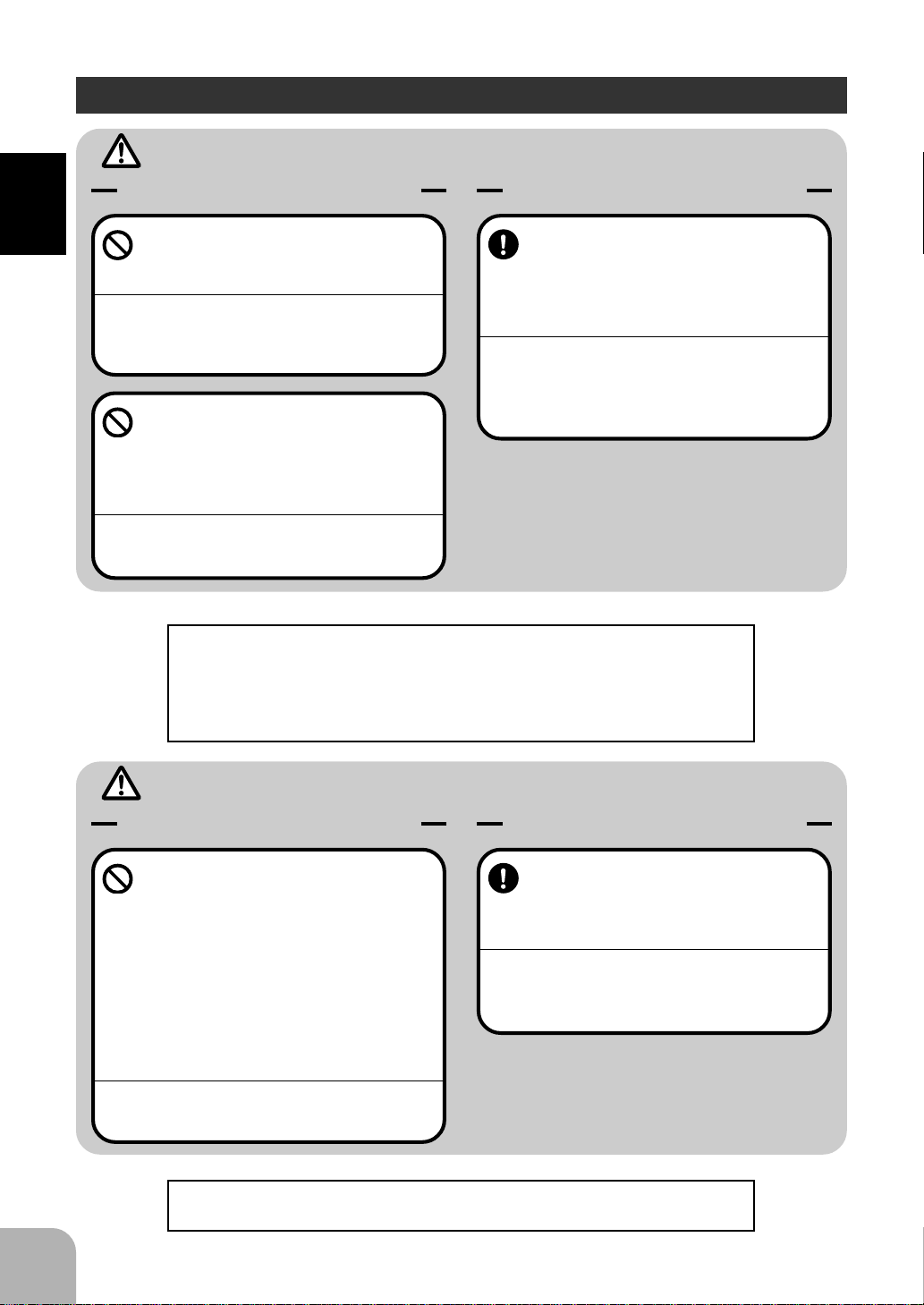
Explanation of Symbols
For Your Safety As Well As That Of Others
The parts of this manual indicated by the following symbols are extremely important
and must be observed.
Symbols Explanation
Indicates a procedure which could lead to a dangerous situ-
Danger
Warning
Caution
Symbols: ; Prohibited ; Mandatory
ation and may cause death or serious injury if ignored and
not performed properly.
Indicates procedures which may lead to dangerous situations and could cause death or serious injury as well as superficial injury and physical damage.
Indicates procedures that may not cause serious injury, but
could lead to physical damage.
6
Page 7
Warning
Operation Precautions
Prohibited Procedures
Do not operate two or more models
on the same frequency at the same
time.
Operating two or more models at same time on the
same frequency will cause interference and loss of
control of both models.
AM, FM (PPM) and PCM are different methods
of modulation. Nonetheless the same frequency
can not be used at the same point in time, regardless of the signal format.
Do not operate outdoors on rainy
days , run through puddles of water or
when visibility is limited.
Should any type of moisture (water or snow) enter any
compoent of the system, erratic opreation and loss of
control may occur.
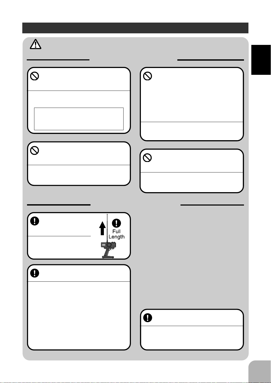
Mandatory Procedures
Extend the transmitter antenna to its full
length.
If the transmitter antenna is not
fully extended the operating
range of the radio will be reduced.
Do not operate in the following
places.
-Near other sites where other radio control
activity may occur.
-Near people or roads.
-On any pond when rowboats are present.
-Near high tension power lines or communication broadcasting antennas.
Interference could cause loss of control . Improper installation of your Radio Control System in your model
could result in serious injury.
Do not operate this R/C system when
you are tired, not feeling well or under
the influence of alcohol or drugs.
Your judgment is impaired and could result in a dangerous situation that may cause serious injury to
yourself as well as others.
For Your Safety As Well As That Of Others
Always perform a operating range
check prior to use.
Problems with the radio control system as well as improper installation in a model could cause loss of control.
(Simple range test method)
Have a friend hold the model, or clamp it down or
place it where the wheels or prop can not come in
contact with any object. Walk away and check to
see if the servos follow the movement of the controls on the transmitter. Should you notice any abnormal operation, Do not operate the model. Also
check to be sure the model memory matches the
model in use.
Check the transmitter antenna to be
sure it is not loose.
If the transmitter antenna works loose, or is disconnected while the model is running signal transmission
will be lost. This will cause you to lose control of the
model..
7
Page 8
Caution
Prohibited Procedures
Do not touch the engine, motor, speed control or any part of
the model that will generate heat while the model is operating
or immediately after its use.
For Your Safety As Well As That Of Others
These parts may be very hot and can cause serious burns.
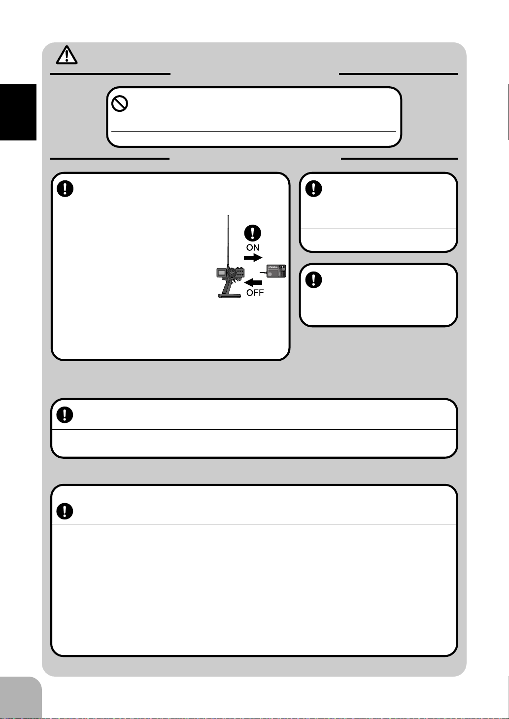
Mandatory Procedures
Turning on the power switches.
Always check the throttle trigger on the
transmitter to be sure it is at the neutral
position.
1. Turn on the transmitter power switch.
2. Turn on the receiver or speed control
power switch.
Turning off the power switches
Always be sure the engine is not
running or the motor is stopped.
1. Turn off the receiver or speed control power switch.
2. Then turn off the transmitter power switch.
If the power switches are turned off in the opposite
order the model may unexpectedly run out of control
and cause a very dangerous situation.
FP-R113F
FM
1
2
3
B/C
When making adjustments to
the model do so with the engine not running or the motor
disconnected.
You may unexpectedly lose control and
create a dangerous situation.
When operating your model
always display a frequency
flag on your transmitter antenna.
When adjusting the transmitter on land while preparing to run (cruise), take measures
so that the wind will not knock over the transmitter.
If the transmitter is knocked over, the throttle stick may be accidentally set to the operating position and you may
lose control.
8
(Fail safe function)
Before running (cruising), check the fail safe function.
Check Method;
Before starting the engine, check the fail safe function as follows:
1) Turn on the transmitter and receiver power switches.
2) Wait at least one minute, then turn off the transmitter power switch. (The transmitter automatically transfers the fail
safe data to the receiver every minute.)
3) Check if the fail safe function moves the servos to the preset position when reception fails.
The fail safe function is a safety feature that minimizes set damage by moving the servos to a preset position when
reception fails. However, if set to a dangerous position, it has the opposite effect. When the reverse function was used
to change the operating direction of a servo, the fail safe function must be reset.
Setting example: Throttle idle or brake position
Page 9
Nicad Battery Handling Precautions
Shock
Prohibited
(Only when Nicad batteries are used)
Warning
Mandatory Procedures
Always check to be sure your batteries have been charged prior to operating the model.
Should the battery go dead while the model is operating loss of control will occur and create a very dangerous situation.
When the model is not being used,
always remove or disconnect the
Nicad battery .
Should the battery be left connected this could create
a dangerous situation if someone accidentally turns
on the receiver power switch. Loss of control would
occur.
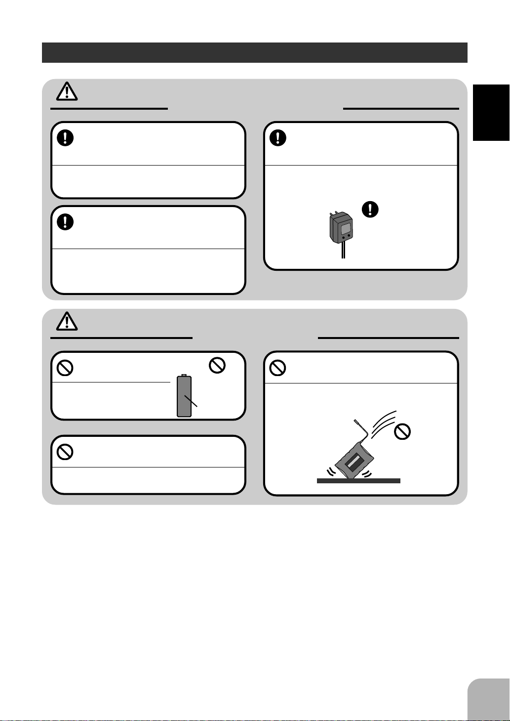
Caution
Prohibited Items
Do not use commercial AA
size Nicad batteries.
Quick charging may cause the
battery contacts to overheat and
damage the battery holder.
Use
prohibited
Nicad AA size
batteries.
To recharge the transmitter Nicad ,
use the special charger made for this
purpose.
Overcharging could cause the Nicad battery to overheat, leak or explode. This may lead to fire, burns,
loss of sight and many other type's of injuries.
Special
Charger
Do not drop the Nicad battery or expose it to strong shocks or vibrations.
The battery may short circuit and overheat, electrolyte
may leak out and cause burns or chemical damage.
For Your Safety As Well As That Of Others
Do not short circuit the Nicad battery
terminals.
Causing a short circuit across the battery terminals
may cause abnormal heating, fire and burns.
9
Page 10
Storage and Disposal Precautions
Warning
Prohibited Procedures
Do not leave the radio system or
For Your Safety As Well As That Of Others
models within the reach of small children.
A small child may accidentally operate the system,
this could cause a dangerous situation and injuries.
Nicad batteries can be very dangerous when mishandled and cause chemical damage.
Do not throw Nicad batteries into a
fire. Do not expose Nicad batteries to
extreme heat. Also do not disassemble or modify a Nicad battery
pack.
Overheating and breakage will cause the electrolyte
to leak from the cells and cause skin burns, loss of
sight as well as other injuries.
<Nicad Battery Electrolyte>
The electrolyte in Nicad batteries is a strong alkali. Should you get even the
smallest amount of the electrolyte in your eyes, DO NOT RUB, wash immediately with water, seek medical attention at once. The electrolyte can cause blindness. If electrolyte comes in contact with your skin or clothes, wash with water
immediately.
Mandatory Procedures
When the system will not be used for
any length of time store the system
with batteries in a discharged state.
Be sure to recharge the batteries prior
to the next time the system is used.
If the batteries are repeatedly recharged in a slightly
discharged state the memory effect of the nicad battery may considerably reduce the capacity . A reduction in operating time will occur even when the batteries are charged for the recommended time.
10
Caution
Prohibited Procedures
Do not store your R/C system in the
following places.
- Where it is extremely hot or cold.
- Where the system will be exposed to direct
sunlight.
- Where the humidity is high.
-Where vibration is prevalent.
-Where dust is prevalent.
-Where the system would be exposed to
steam and condensation.
Storing your R/C system under adverse conditions
could cause deformation and numerous problems
with opreation.
<Nicad Battery Recycling>
A used Nicad battery is valuable resource. Insulate the battery terminals and
dispose the battery by taking it to a battery recycling center.
Mandatory Procedure
If the system will not be used for a
long period of time remove the batteries from the transmitter and model
and store in a cool dry place.
If the batteries are left in the transmitter electrolyte
may leak and damage the transmitter. This applies to
the model also, remove the batteries from it also to
prevent damage.
Page 11

Other Precautions
Caution
Prohibited Procedures
Do not expose plastic parts to fuel,
motor spray, waste oil or exhaust.
The fuel, motor spray, waste oil and exhaust will penetrate and damage the plastic.
Mandatory Procedures
Always use only genuine Futaba
transmitters, receivers, servos, FET
amps (electronic speed
controls),Nicad batteries and other
optional accessories.
Futaba will not be responsible for problems caused by
the use of other than Futaba genuine parts. Use the
parts specified in the instruction manual and catalog.
For Your Safety As Well As That Of Others
11
Page 12

Before Using
Features
- Eight Model Memories/Eight More Models Can Be Added By
Using the Data Pac
English and Japanese Katakana characters may be used to assign each model a name.
Model memories with slightly different settings can be easily created by using the
model copy function. Also, eight more models can be added by using the optional
Data Pac (DP-16K).
- Large LCD display
Before Using
Constantly displays all the information needed for monitoring. The large characters
can be easily read when making adjustments.
- Three Function Selection Modes
New menu configuration allows direct access to the most frequently used functions.
(Direct Mode/Select Mode/Set-Up Mode)
- Second Dual Rate (D/R2)
Lets you change the steering angle with one touch while running.
- Anti-Skid Brake System (A. B. S. Function)(A.B.S.)
Allows braking without the tires losing their grip on the track even when braking gas
powered cars on corners.
- Throttle Acceleration (TH.ACC)
Gas powered cars have a lag time before the clutch is engaged or the brakes are
applied. This function minimizes this lag time.
- Traction Control (TRAC)
When trigger operation is performed suddenly on slick surfaces, the wheels merely
spin and the car does not accelerate smoothly. By setting the Traction Control function, operation can be performed smoothly and pleasantly and battery consumption
can be reduced.
- Start (START)
On a slick surface, if the throttle trigger is set to full throttle at the start of a race, the
wheels will spin and the car will not accelerate smoothly. When the Start function is
set, merely pulling the throttle trigger forward causes the throttle servo to automatically move to a preset position and the car to accelerate smoothly.
- Steering Speed (ST.SPD)
Allows you to adjust the steering servo speed to match your style of driving.
12
Page 13

- Advanced Timer (TIMER)
The racing timer (lap timer) can record the total time and up to 99 laps. The timer can
be automatically activated by trigger operation. An alarm can be set from 30 second
before time is up.
A Navigation timer that is effective in practice runs can alert you to the target lap.
- Digital Trim w/Reset Function
The trim position is constantly displayed on the LCD screen. One-step servo travel
can also be adjusted.
Steering and throttle trim adjustments have no effect on the maximum servo travel.
- Trim Function Selection
Allows you to assign various functions to the trimmers (digital trim, grip dial, knob).
All the trims are digital, so they do not have to be repositioned for each model.
- Switch Function Selection
Allows you to assign various functions to the two switches.
- Left Hand Reversible
- Black Transmitter Antenna
Before Using
- New Light Weight Design and Extraordinary Balance
- Tension Adjustment
Steering wheel spring tension can be adjusted from the outside.
- Trigger Stop Function (Mechanical ATL)
The mechanical trigger stop can be used as ATL.
- Display Switch
Functions can be set without transmitting a signal.
- Body Rest (Option)
- Receiver w/DSC Function (Connection Cord is Optional)
FM: R113F, PCM: R113iP
13
Page 14
Set Contents
After opening the box, first check if the contents conform to the following. The contents depend on the set as shown below.
Transmitter T3PJ SUPER
RF module
Before Using
Receiver R113F(FM) or R113iP(PCM)
Servo S9402, S9304 or (none)
Miscellaneous
- If any of the set contents are missing, or you have any questions, please contact you
dealer.
Caution
TJ-FM
*Installed in transmitter.
Transmitter Ni-cad battery pack NT8F700B
or Battery box
*Installed in transmitter.
Receiver switch
Instruction manual
14
Always use only genuine Futaba transmitter, receiver, FET amp, Ni-cad battery and
other optional parts.
Futaba will not be responsible for damage caused by other than genuine Futaba parts and components. Use only
the genuine Futaba parts and components listed in the instruction manual and catalog.
Page 15
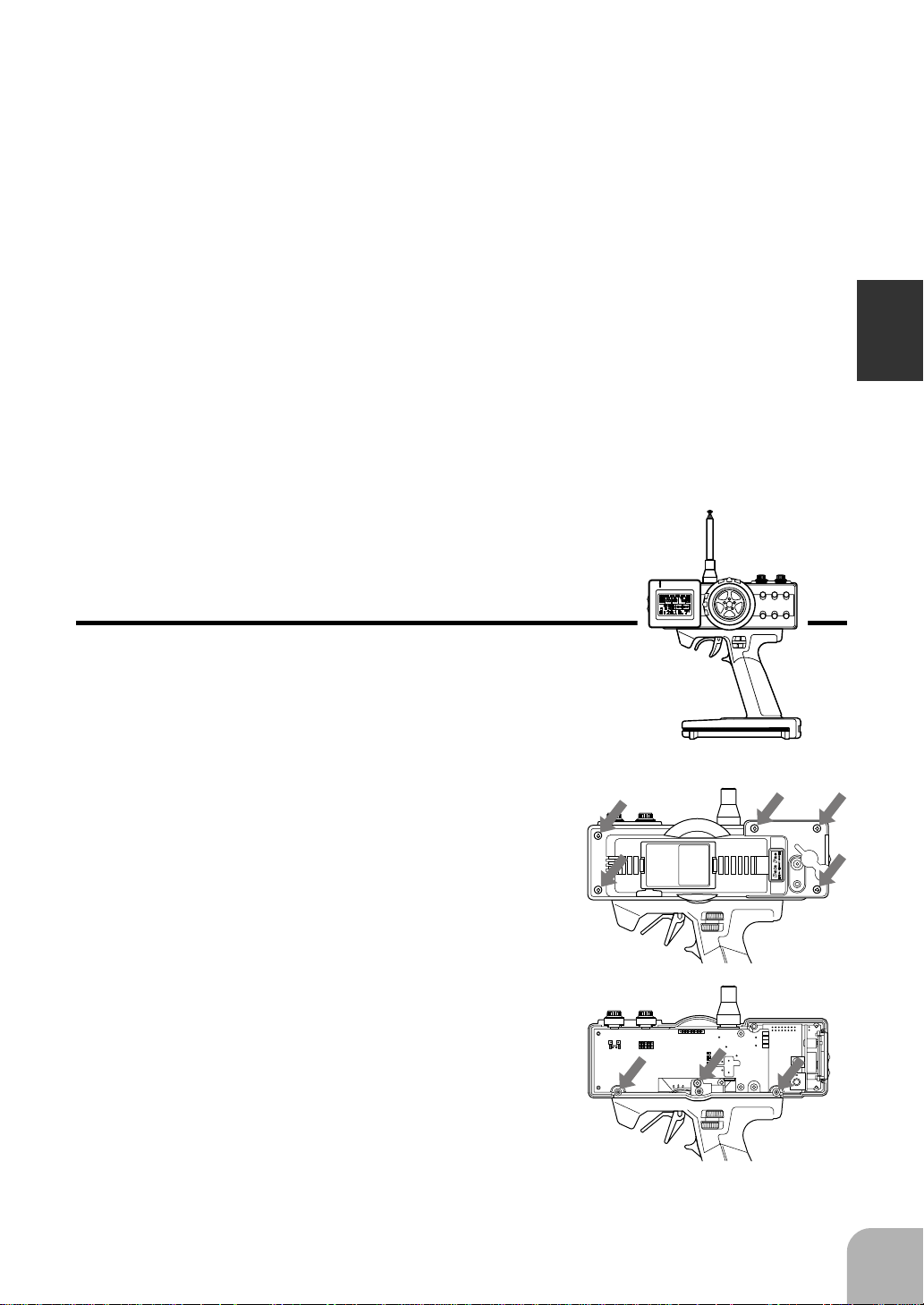
Nomenclature
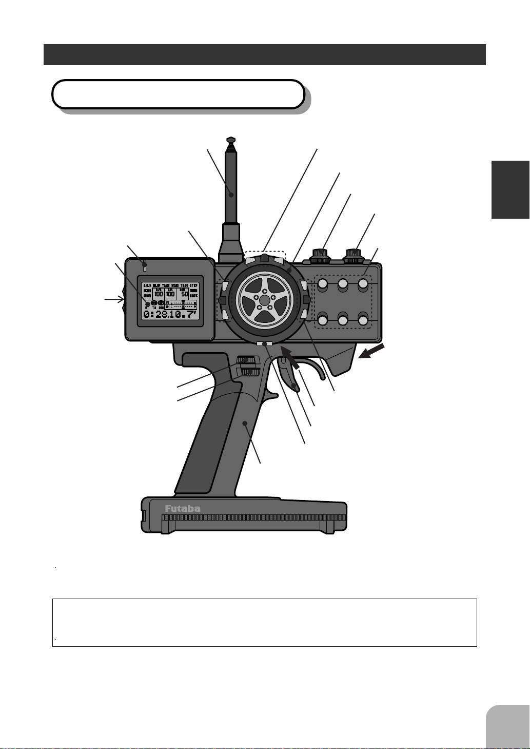
Transmitter T3PJ SUPER (Front)
Antenna
(See page 16 for the operating instructions.)
Steering trim (DT1)
Steering wheel
(See page 16 for the operating
instructions.)
Throttle trim (DT2)
Pilot lamp
LCD screen
PILOT
Power
switch
MULTI FUNCTION DISPLAY
(See page 16 for the
operating instructions.)
(GD1)
Steering dual rate dial
ATL dial (GD2)
(See page 16 for the
operating instructions.)
DIRECT
Throttle trigger
Timer switch (PSH)
Grip Handle
Traction control switch
(SLD)
CH3 knob (KNOB)
Edit keys
ST.EXP
M.SEL
UP
+
SETUP
RESET
DOWNSELECT
-
ATVTH.EXP
CUSTOM
(See page 17 for the
adjustment instructions.)
Mechanical ATL
adjusting screw
(See page 16 for the operating
instructions.)
Digital trim 3 (DT3)
Wheel tension
adjusting screw
Before Using
(See page 17.)
3PJ SUPER DIGITAL PROPORTIONAL RADIO CONTROL SYSTEM
*The switches, knobs, and trimmers in the figure are shown in the initial setting position.
Precautions when turning the power switch on and off.
When the data was changed using the edit keys or trim levers, wait at least two seconds before turning off the power. If the power is turned off within two seconds after
the data was changed, the new data will not be written to memory.
15
Page 16
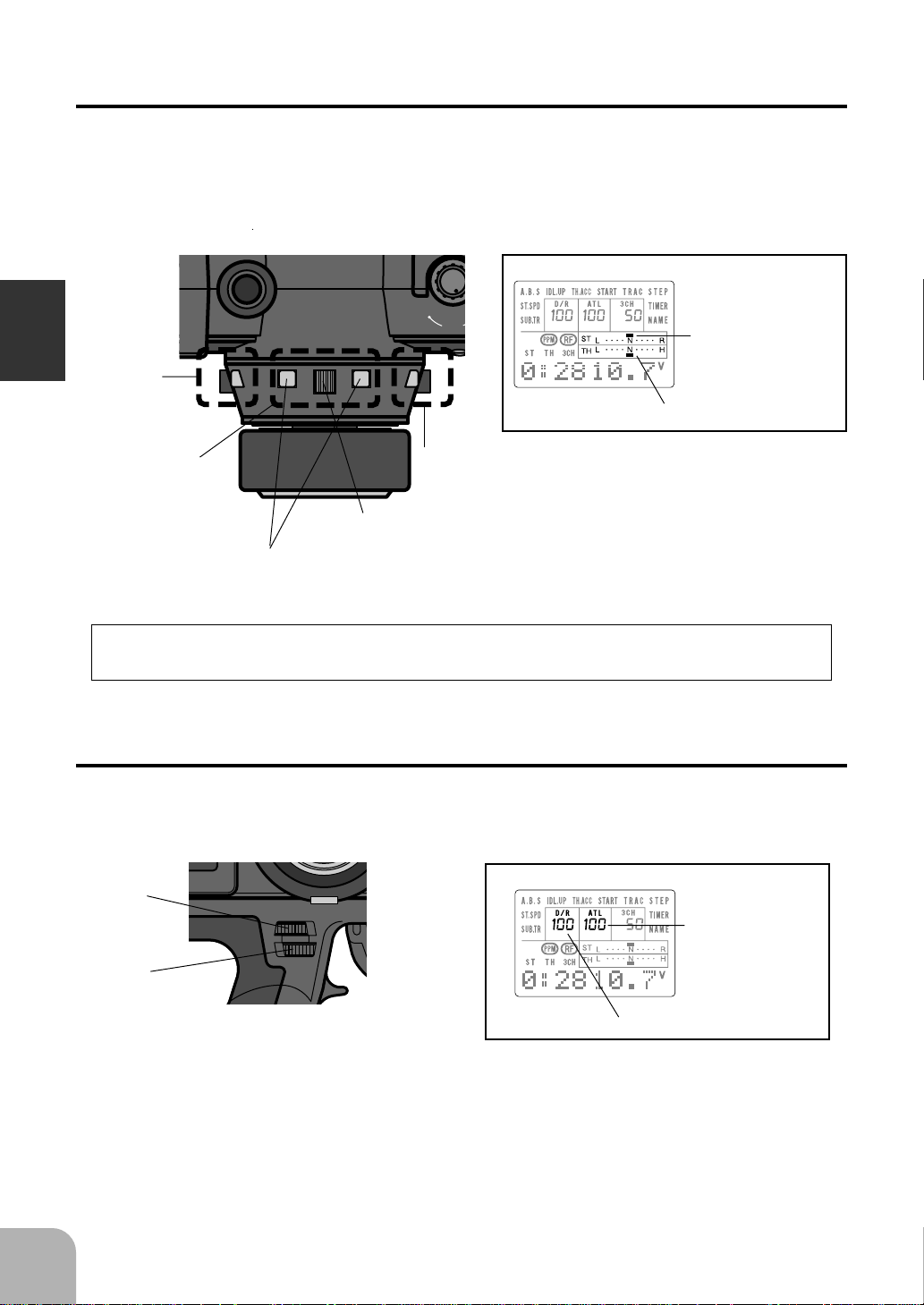
Digital Trim Operation
(Initial settings: DT1: Steering trim, DT2: Throttle trim, DT3: -------)
Operating by the lever: Push the lever to the left or right (up or down).
Operating by push button switch: Press the push button switch in the desired direction.
The current position is displayed on the LCD screen.
ON
SLD
Steering trim display
Before Using
DT2
DT1
Trim Operation
With the center trim feature, trim adjustments have no effect on the maximum servo
travel. This prevents the linkages from binding when adjustments are made.
Grip dial operation
(Initial settings: GD1=Steering D/R, GD2=ATL)
Operate the dials by turning them. The current set value is displayed on the LCD
screen.
GD1
DT.1
Lever
Push button switch
DT3
Throttle trim display
- Each step is indicated by a tone.
- When the trim exceeds the maximum trim adjustment
range, the tone will change pitch and the lever will not
move any farther.
- Return to the neutral position (center) by pressing both
the push button switches simultaneously for about one
second.
ATL display
16
GD2
Steering D/R display
- A click sound is made at each step.
- When the maximum position is reached at each side, the
tone of the click changes. Thereafter, the set value does
not change.
Page 17
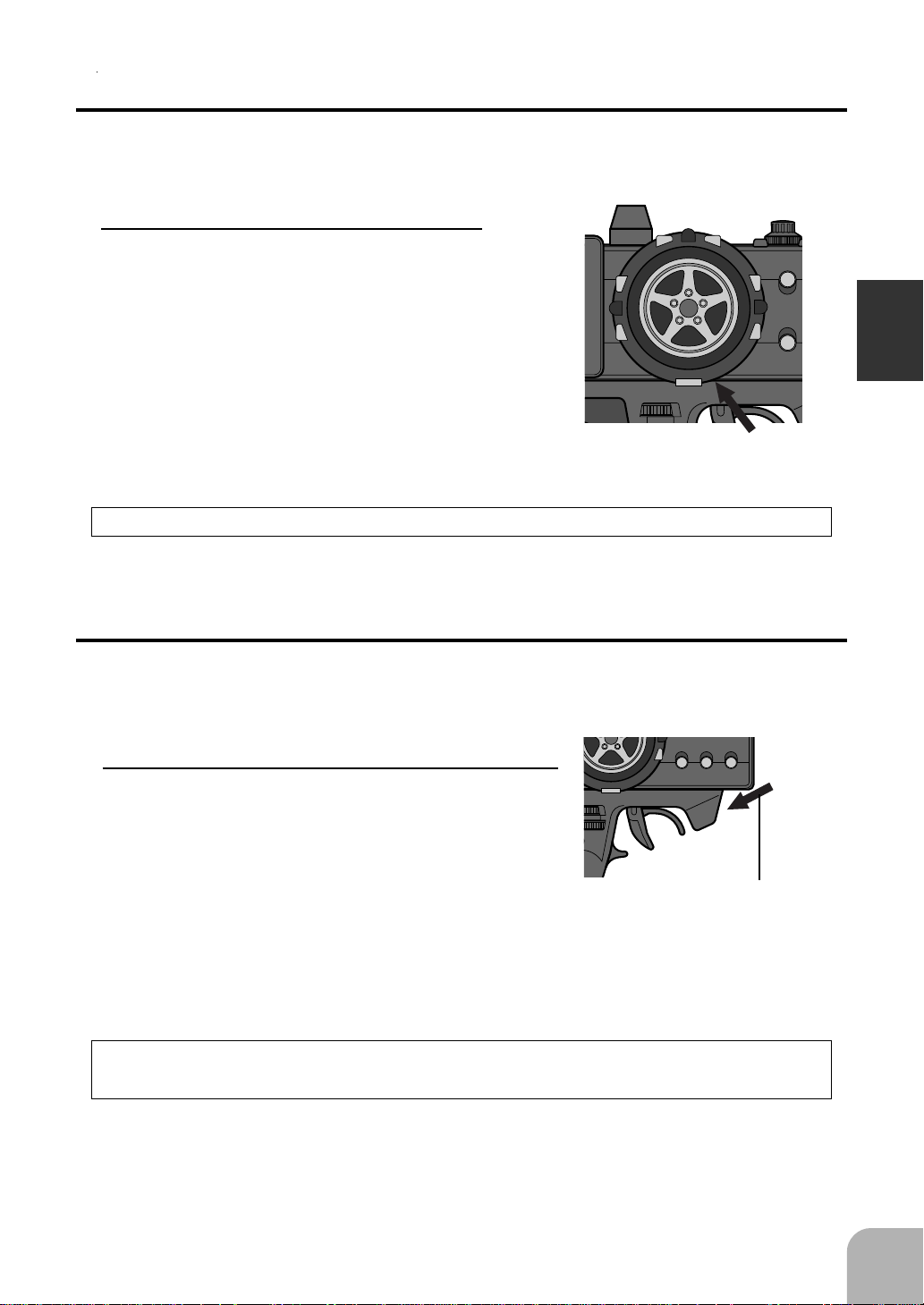
Wheel Tension Adjustment
Make this adjustment when you want to change the steering wheel spring tension.
Adjustment
Turn the screw inside the adjusting
hole using a 1.5mm hex wrench.
- Turning the adjusting screw
clockwise, increases the spring
tension.
Caution
If turned too far counterclockwise, the adjusting screw may fall out.
DIRECT
SELECT
TH.EXP
Tension adjusting
screw
Before Using
Mechanical ATL Adjustment
Make this adjustment when you want to make the throttle trigger brake (back) side
stroke narrower.
Adjustment
Using a Phillips screwdriver, adjust the trigger
brake (back) side stroke by turning the screw
through the adjusting hole indicated by the arrow in the figure. (The screw moves the
throttle trigger stopper.)
- When the adjusting screw is turned clockwise, the
stroke becomes narrower.
Caution
When the stroke was adjusted, the throttle servo travel must be adjusted by data setting.
Mechanical ATL
adjusting screw
SETUP
RESET
DOWNSELECT
-
ATVTH.EXP
CUSTOM
17
Page 18
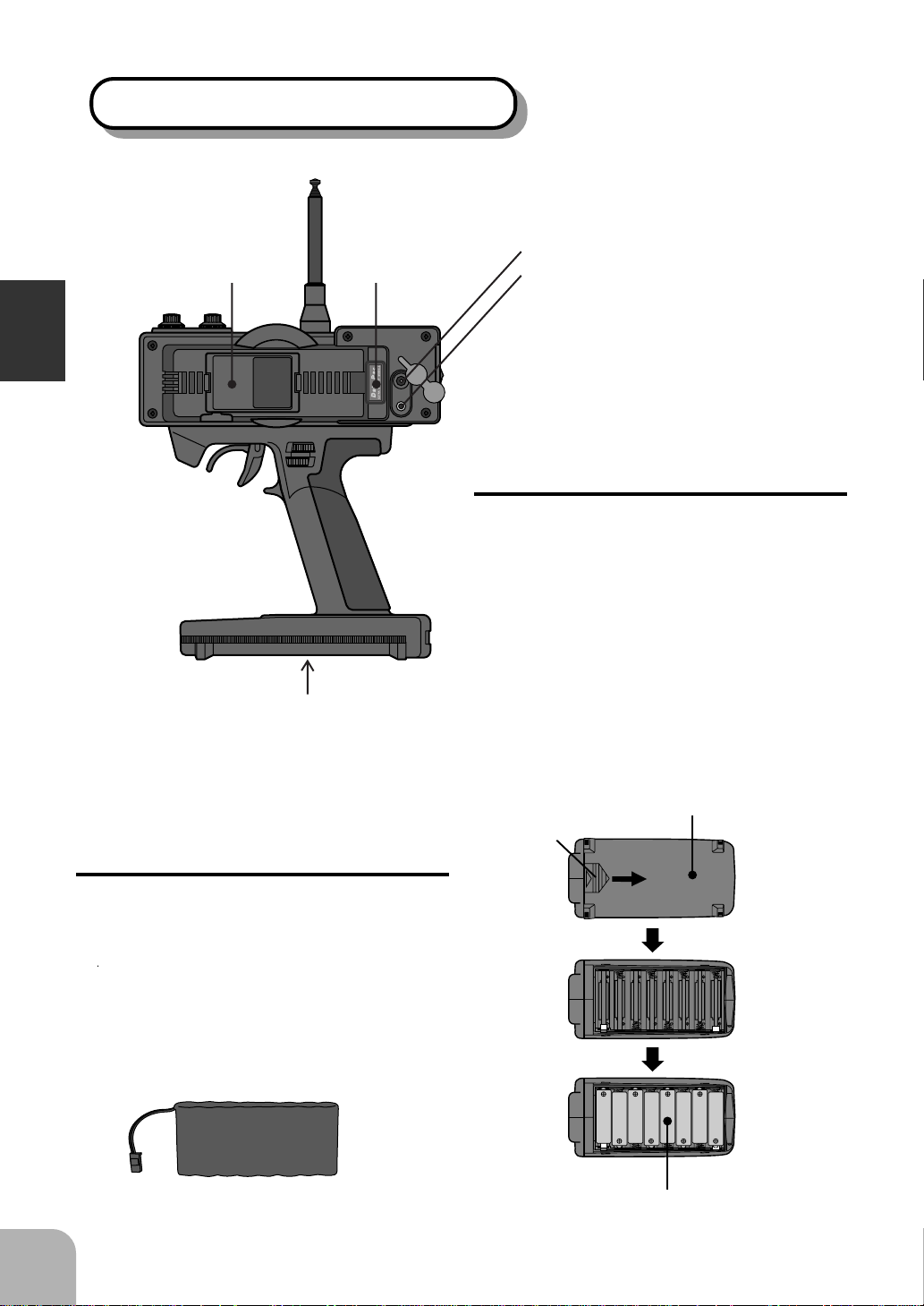
Transmitter T3PJ SUPER (Rear)
(See page 20 for the
(See page 20 for the
handling instructions.)
RF module
handling instructions.)
DP-16K
Data Pac
Charging jack
DSC jack
(See page 103 for the handling instructions.)
(The DSC cord sold separately is necessary.)
Before Using
Battery cover
- When changing the Ni-cad battery pack, or dry
cell batteries, remove this cover.
Ni-cad Battery
Replacement
(For Ni-cad battery system)
The Ni-cad battery is connected by a
connector so that it can be removed
when you will not be using the transmitter for a long time, or when replacing a dead battery with a spare battery.
- Always use an NT8F700B Ni-cad battery.
CHG
DSC
Dry cell Battery
Replacement
(For dry cell battery system)
1. Slide the transmitter battery
cover in the arrow direction
while pressing the part shown
in the figure.
2. Load the eight batteries in accordance with the polarity
markings on the battery holder.
3. Slide the battery cover back
onto the transmitter.
While pressing
this part.
Battery cover
18
Ni-cad battery
NT8F700B
Dry cell battery (x8)
Page 19
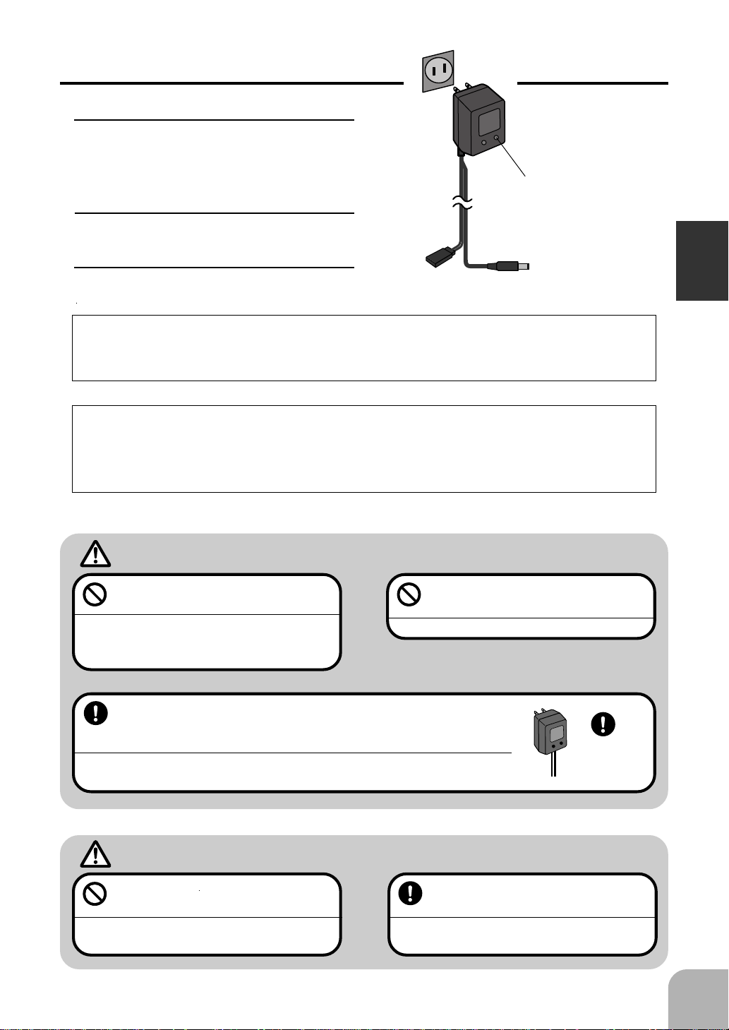
Charging the Ni-cad Battery
AC outlet
Charging
Charger
1. Plug the transmitter cord of the
special charger into the charging jack on the rear of the transmitter.
2. Plug the charger into an AC outlet.
Transmitter charging
LED
Cord to transmitter
charging jack
3. Check that the charging LED
lights.
When charging the NT8F700B Ni-cad battery with the special charger, allow about
15 hours for charging. If the transmitter has not been used for some time, cycle the
battery by charging and discharging it two or three times.
Diode Protection
The transmitter charging circuit is equipped with a 1.5A diode to prevent short circuits. If the battery is charged with a quick charger for other than digital proportional
R/C sets, it may not be fully charged and the circuits inside the transmitter may be
damaged.
Before Using
Warning
Never plug it into an outlet other
than indicated voltage.
Plugging the charger into the wrong outlet may result in an explosion, sparking, or fire.
Always use the special charger or a quick charger for digital proportional R/C sets to charge a digital proportional R/C set Ni-cad
battery.
Overcharging a Ni-cad battery can result in burns, fire, injuries, or loss of sight due to
overheating, breakage, or electrolyte leakage.
Do not insert and remove the
charger when you hands are wet.
It may cause an electric shock.
Caution
Never try to recharge a dry cell battery.
The transmitter may be damaged or the battery
electrolyte may leak or the battery may break.
When the charger is not in use, disconnect it from the AC outlet.
Do this to prevent accidents and to avoid overheating.
Use the
special
charger.
19
Page 20
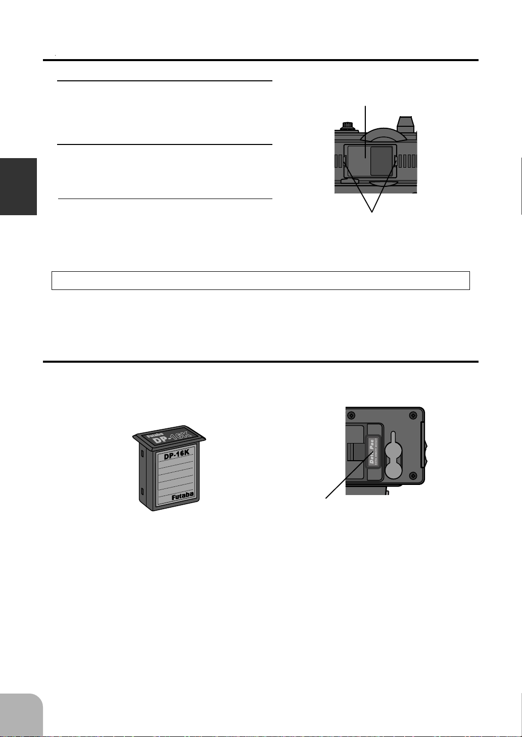
RF Module
Removal
1. Pull the RF module forward while
pressing the tabs at the left and
right inward.
Insertion
1. Insert the RF module while being
careful not to bend the transmitter
side connector pins.
RF module
Before Using
at the left and right snap in place
with a “click”.
RF Module Temperature Rise
The temperature of the RF module will rise slightly during operation.
Handling the Data Pack
The set data for 8 units can be stored in the 3PJ SUPER transmitter body and the set
data for 8 more units can be stored in a DP-16K (Option) removable data pack.
Data pack DP-16K
(Option)
2. Insert the RF module until the tabs
Tabs
CHG
DSC
20
Data pack insertion slot
-Grasp the dustproof cap and insert
the data pack fully.
Inserting and removing the data pack
Always turn off the transmitter power before removing and inserting the data pack.
Data pack initialization
When the data pack is used and the power is turned on for the first time, the data pack
must be initialized before it can be used with this transmitter. When "CAM-INI?" is
displayed on the screen after the power is turned on, press the "+" key. This automatically initializes the data pack. This operation is unnecessary thereafter.
Page 21
3PJ SUPER and 3VC transmitter data pack compabilitily
- Note that the digital trim 3 (DT3) and slide switch (SLD) initialization values are
different.
- The 3VC transmitter does not have a digital trim function reverse function. There-
fore, when the 3PJ SUPER transmitter copied data to a 3VC transmitter, the 3VC
ignores the copied data. However, since the data is stored as is, when the data is recopied to the 3PJ SUPER transmitter, the 3PJ SUPER will operate using the original
settings.
Set data backup
The set data of each function (transmitter body and data pack) of the 3PJ SUPER
transmitter is stored in a memory element that does not require a backup battery.
Therefore, the 3PJ SUPER transmitter can be used without paying attention to the
backup battery life.
Before Using
Adaptation For Left-Hand Use
This transmitter can be modified for left-hand use.
1. Remove the Transmitter Battery. Carefully remove the 5 screws from the rear case cover.
Do not use excessive force to get the case
apart.
2. Carefully remove the 2 gold screws and 1
black screw at the top of the handle. Be very
careful the Display switch cover will fall out.
3. Rotate the handle and reinstall the screws in
same position as they were removed. Make
sure you do not pinch or put excessive pressure no any wires. Do not overtighten the
screws.
4. Place the Display switch cover in position and
reinstall the rear case cover. Again be careful
and do not overtighten the screws.
PILOT
DIRECT
ST.EXP
M.SEL
UP
+
SETUP
RESET
DOWN
-
ATVTH.EXP
CUSTOM
CHG
DSC
21
Page 22
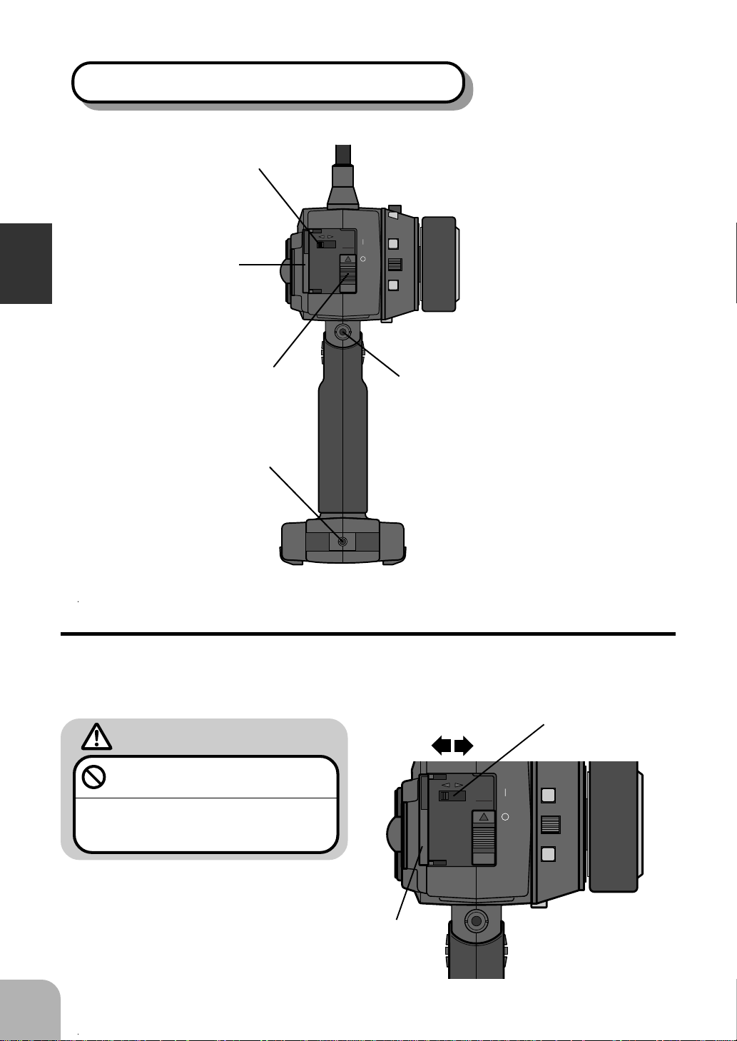
Transmitter T3PJ SUPER (Side View)
Before Using
Display switch
Cover
Power switch
Body rest
mounting hole
OFF ON
DISPLAY
SW
POWER
ON
DT.2
Sound port
- Use a commercial earphone.
(Use a radio earphone with a 3.5mm diameter plug.)
- When the surroundings are noisy during races, etc.,
you can listen to the alarm tone using an earphone.
The alarm tone can also be heard from the transmitter.
22
Display Switch
If the Display Switch is turned on without turning on the power switch, the transmitter data can be set without transmitting a signal.
Warning
Never turn on the power switch
while using this function.
If the power switch is turned on, a signal will be
transmitted and will interfere with other models
operating on the same frequency.
OFF
OFF ON
Cover
DISPLAY
ON
POWER
ON
SW
Display Switch
DT.2
Page 23
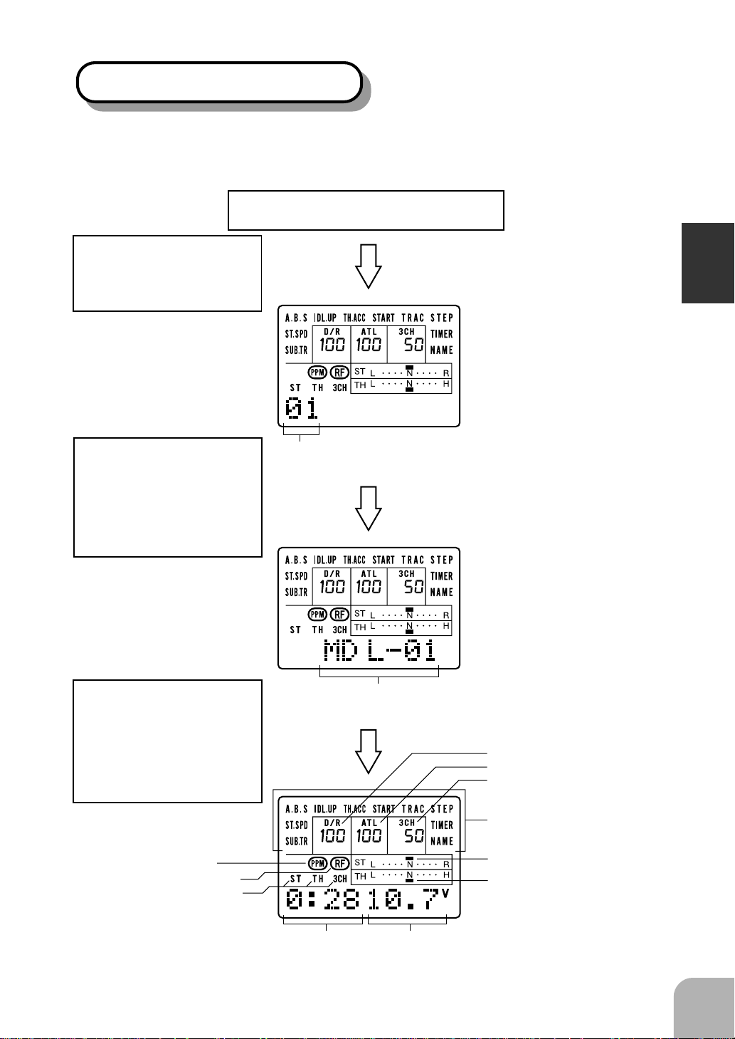
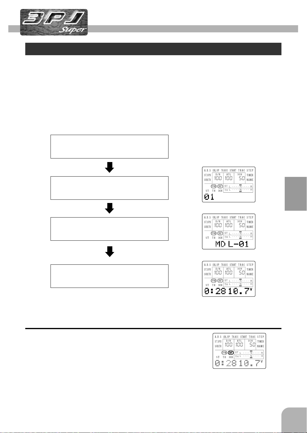
LCD Screen and Edit Keys
When the transmitter power switch is turned on, the model memory No. and model
name currently called are temporarily displayed for confirmation.
Turn on the power switch
A tone will sound to
show that the power is
on.
Model No. (1~8)After the model No. is
displayed for about one
second, the LCD will
switch to the model
name display.
Before Using
After the model name is
displayed for several
seconds, the LCD will
switch to the timer and
voltage display.
PCM/PPM display
RF output monitor
Channel selection display
Total time display
(Hours : Minutes)
Model name (6 characters)
D/R function rate display
ATL function rate display
Channel 3 position display
Select mode menu
Steering trim display
Throttle trim display
Battery voltage display
23
Page 24
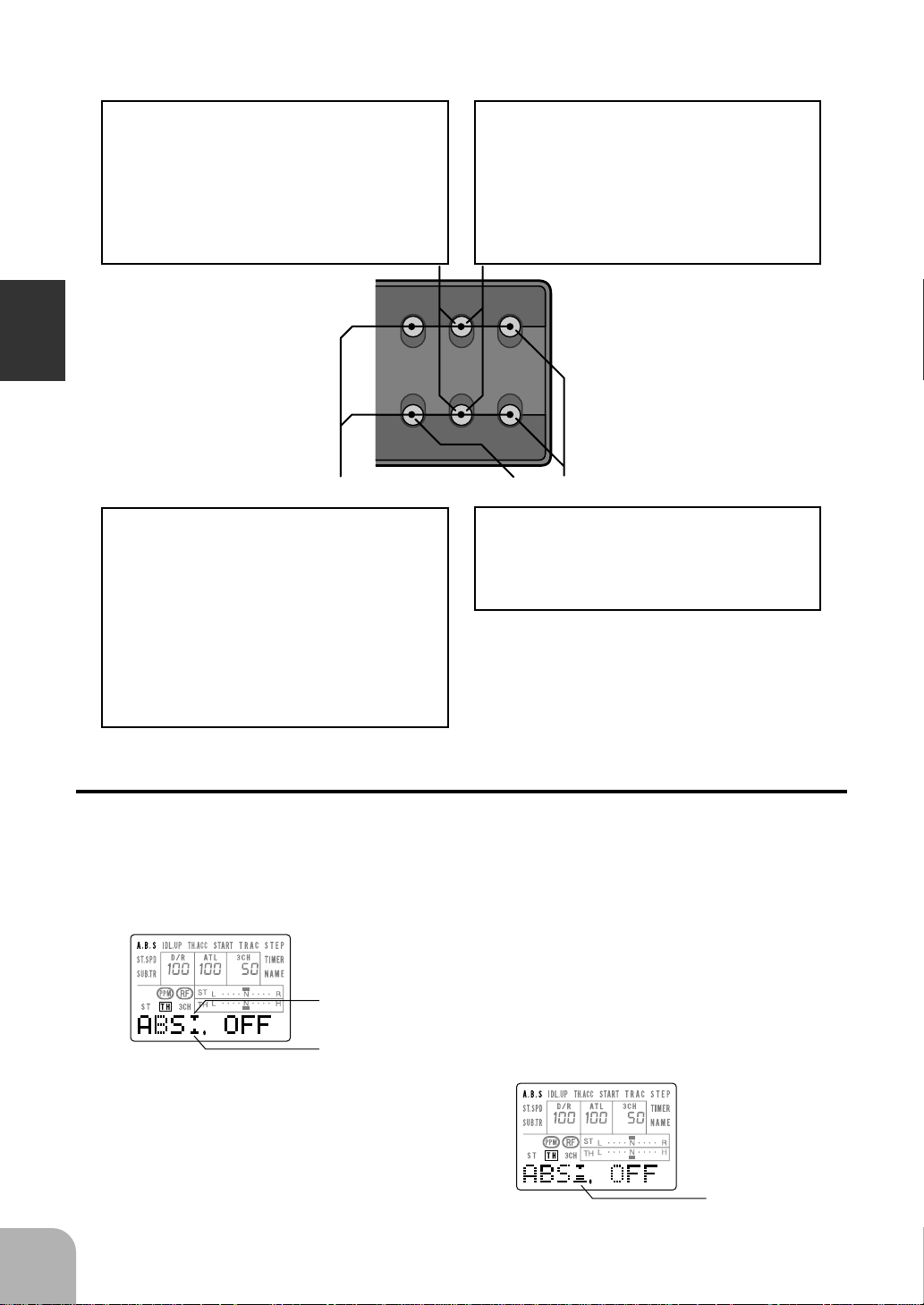
SET-UP Mode Function Selection
To call the function set-up screen in the SET-UP
mode, press the UP and DOWN keys simultaneously.
After that, select the function with the UP or DOWN
key.
To end the SET-UP mode, press the UP and DOWN
keys simultaneously again, or press the DIRECT key
twice.
SELECT Mode Function Selection
To call the function set-up screen in the SELECT
mode, press the UP or DOWN key at the initial
screen.
After that, select the function with the UP or down
KEY.
To end the SELECT mode, return to the initial
screen by pressing the UP or DOWN key similarly,
or press the DIRECT key twice.
Before Using
DIRECT Mode Function Selection
To call the function set-up screen in the DIRECT
mode, first press the DIRECT key, then select the
function by pressing the key corresponding to the
function desired as shown below.
- Steering EXP key (ST.EXP)
- Model select key (M.SEL)
- Throttle EXP key (TH.EXP)
-ATV key (ATV)
- Custom key (CUSTOM)
To end the DIRECT mode, press the DIRECT key
twice.
Switch screen display
For functions that can use the push-button switch (PSH) or slide switch (SLD), the
following symbols are displayed on the setup screen of the relavent function.
Edit keys
DIRECT ST.EXP M.SEL
SELECT DOWN
TH.EXP ATV CUSTOM
UP
SETUP RESET
+
-
Data Entry Keys
Use the SELECT key to select the set-up item and
channel at the function set-up screen.
Use the + and - keys to enter data. To reset (return to
initial value) the entered data, press the + and - keys
simultaneously.
24
(A.B.S. function example)
*For the A.B.S function, both switches can be set.
[If this is displayed, SLD can be set]
[If this is displayed, PSH can be set]
When the screen switch display is enlarged as
shown at the right, that switch can be set.
[Display is enlarged]
Page 25
LCD Screen Contrast
The LCD screen contrast can be adjusted. (For more information, see page 94.)
Caution
Do not adjust the contrast so that the LCD is too bright or too dark.
When the display cannot be read due to a temperature change, data cannot be set.
LCD Screen Temperature Change
In the following cases, the LCD may become difficult to read due to a temperature
change.
- On hot summer days and cold winter days, the LCD may be easy to read indoors, but difficult to
read outdoors.
- If the contrast is too bright or too dark, temperature changes and lighting conditions may cause the
screen to become difficult to read.
Contrast Adjustment
1 Turn on the transmitter power.
2 Press the DIRECT key twice.
3 Press the UP and DOWN keys
simultaneously.
4 Press the DOWN key six times.
5 If the screen is too dark, adjust
the screen to the point where it
can be easily read. If the screen
is too dark, press the - key. If the
screen is too bright, press the +
key.
Before Using
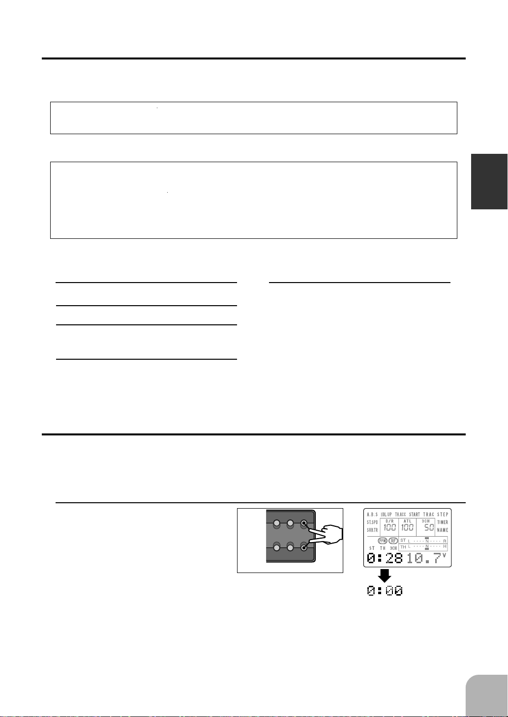
Total Timer
The total timer shows the total time from the last time it was reset.
Reset
1 At the total time display, press
DIRECT ST.EXP M.SEL
UP
the + and - keys simultaneously for about one second.
SELECT DOWN
TH.EXP ATV CUSTOM
SETUP RESET
+
-
25
Page 26
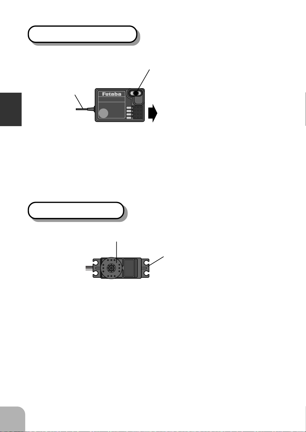
Receiver R113F/R113iP
Antenna
Before Using
For the receiver, servos, and other connections, see page 27. For the DSC cord (option) connections, see page 103.
FP-R113F
FM
1
2
3
B/C
R113F/R113iP
receiver
Crystal
When changing the frequency, use the
specified Futaba crystal set.
Connectors
1: Steering servo (CH1)
2: Throttle servo (CH2)
3: CH3 servo (CH3)
B/C: Power connector/DSC connector
Servo S9402 / S9304
Servo horn
to Receiver
Mounting flange
<Accessory>
The following items are provided for setting:
- Spare servo horn
- Parts for servo installation
(For the installation precautions, see page 28.)
26
Page 27
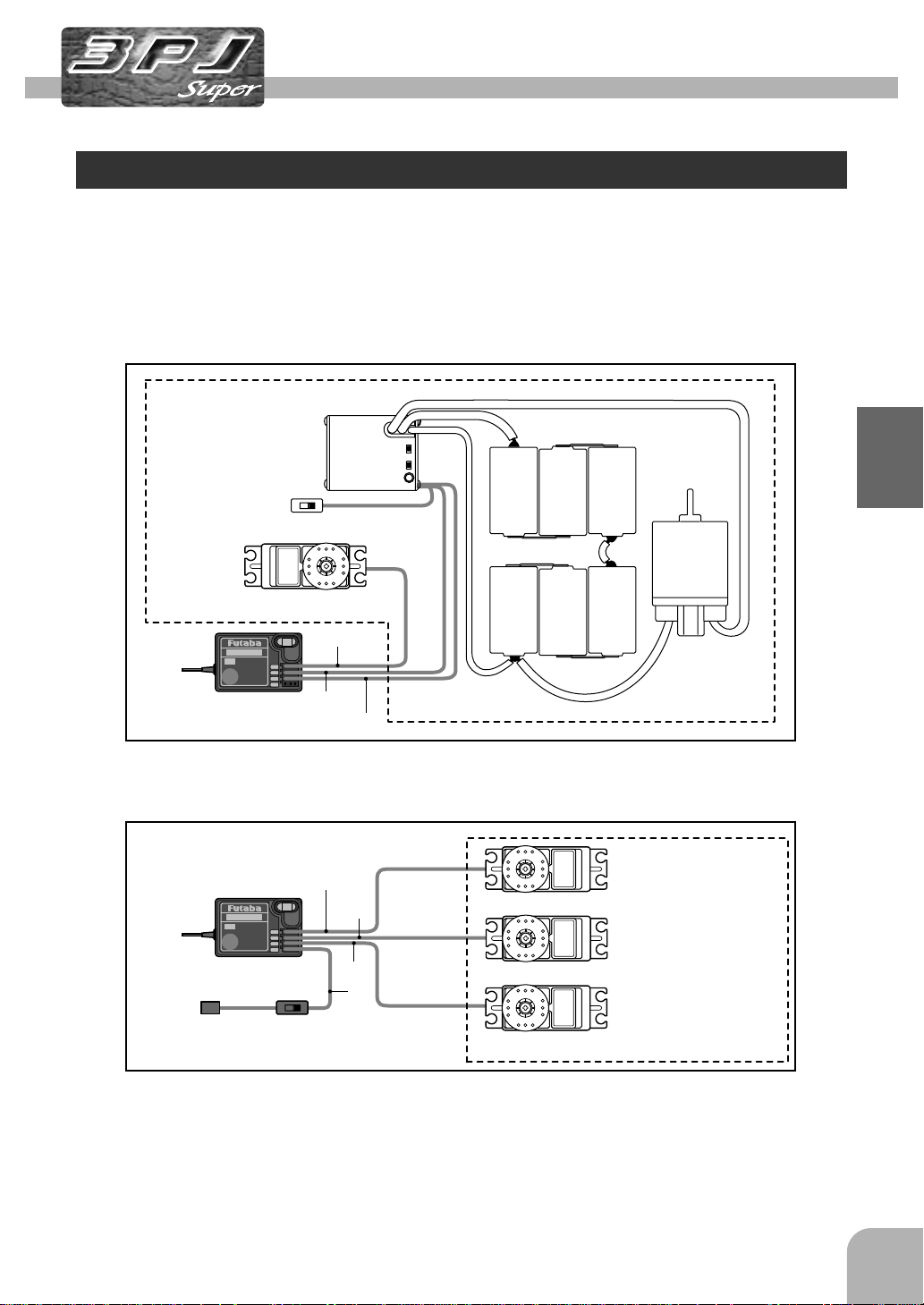
Installation
Receiver and Servo Connections
When connecting and installing the receiver and servos, read the “Installation Safety
Precautions” on the next page.
Installation When An FET Amp Is Used (MC510CFET Amp)
FET amp
Ni-cad battery
-
Receiver
Installation For Gas Powered Models
Receiver
To receiver
battery
Steering servo
CH1
1
2
3
B/C
CH2
CH3
CH1
CH2
1
2
3
B/C
CH3
B
Receiver
switch
Installation
+
Motor
Steering servo
Throttle servo
Channel 3 servo
27
Page 28
Installation Safety Precautions
Warning
Connector Connections
Be sure the receiver, servo, crystal
and connectors are fully and firmly
connected.
If vibration from the model cause a connector to work
loose while the model is in operation. You may lose
control .
Receiver Vibration Damping and
Waterproofing
(Car)
Dampen the vibration to the receiver
by mounting to the chassis or mounting plate with thick double sided tape
Installation
in electric powered models. In gas
powered models wrap the receiver in
foam and mount it where the vibration
is the least prevalent.
(Boat)
Dampen the vibration to the receiver
by wrapping it in foam. Waterproof by
placing it in plastic bag or watertight
radio box in model.
If the receiver is subjected to strong vibration or shock
erratic or loss of control may occur. If any moisture
comes in contact the receiver and servos you may
expertise the same result as well as damage to the
system.
Electronic speed control
Install the heat sinks where they will
not come in contact with aluminum,
carbon fiber or other parts that conduct electricity.
If the FET Amp (Electronic speed control) heat sinks
touch other materials that conduct electricity a short
circuit could occur. This could result in loss of control
and damage to the system.
Servo Throw
Operate each servo over its full stroke
and be sure the linkage does not bind
or is loose.
The continuous application of unreasonable force to a
servo may cause damage and excessive battery
drain.
Servo Installation
When you install the servos always
use the rubber grommets provided in
servo hardware bags. Mount the servos so they do not directly come in
contact with the mount.
If the servo case comes in direct contact with the
mount vibration will be directly transmitted to the
servo.
If this condition continues for a long time the servo
may be damaged and control will be lost.
28
Receiver Antenna
Do not cut or bundle the receiver antenna
Do not bundle the receiver antenna
together with the servo lead wires
Keep the receiver antenna at least 1
inch away from the motor and battery
and wires that handle heavy current
loads..
Cutting, bundling or routing the receiver antenna near
any devise that produce noise will reduce the operating range of the system and result in loss of control.
*Also route the receiver antenna away from metal,
carbon fiber and other parts that conduct electricity. These parts can transmit high frequency noise.
Motor Noise Suppression
Always install capacitors to suppress
noise when electric motors are used.
If capacitors are not properly installed you could experience erratic operation and reduced range as well
as loss of control.
Other Noise Suppression Methods
Be sure there are no metal parts in
your model which under vibration can
come in contact with other metal
parts.
Metal to metal contacts under vibration will omit a high
frequency noise that will effect the receivers performance. You could experience erratic operation and
reduced range as well as loss of control.
Page 29
Initial Set-Up
Preparations (Transmitter)
Before setting the transmitter functions, check and set items 1 to 3 below.
(Display when power switch turned on)
When the power switch is turned on, the currently selected model number is displayed. Check if this number is the model number you want to set-up. To change the
model number, use the Model Select function (page 44).
Turn on the transmitter power.
The model number is displayed
for about one second.
The model name is displayed for
about two seconds.
The total timer and voltage dis-
レバー類の準備
play initial screen is displayed.
(Total timer & voltage display)
1. RF Output Check
If signals are output normally, RF output monitor “RF”
will be displayed on the screen.
If RF is not displayed, check if the transmitter crystal and
RF module are installed.
If the transmitter is abnormal or faulty, contact your
Futaba dealer.
(Model No.)
(Model name)
Initial Set-Up
29
Page 30
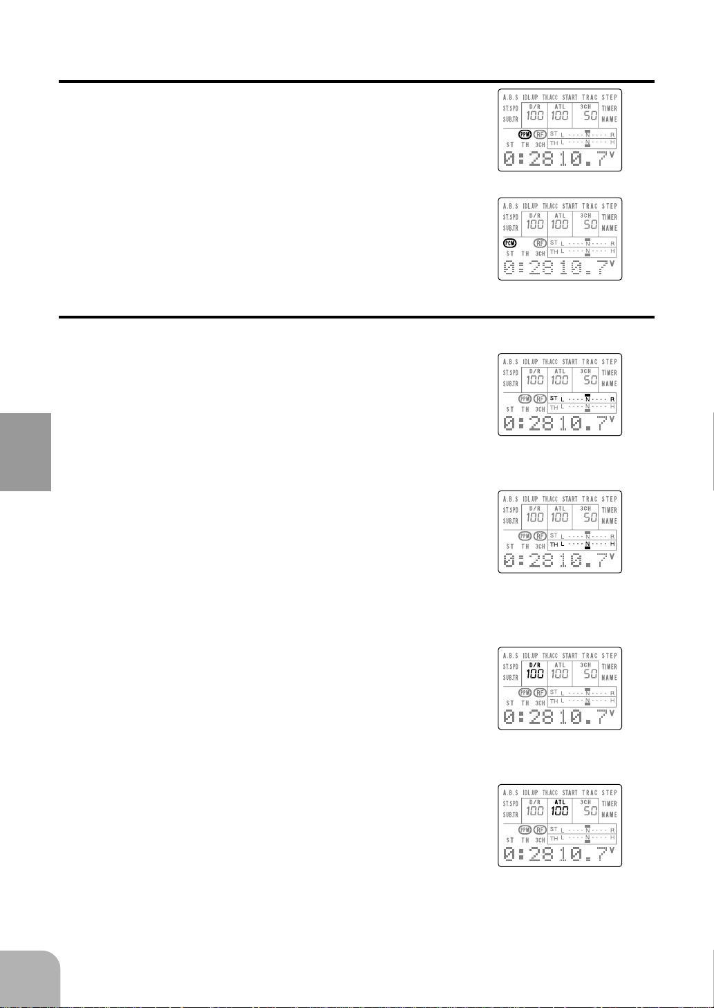
2. Modulation Mode Check
The T3PJ SUPER transmitter output signal format can
be changed to match the type of receiver. Check if the
modulation mode is set to match the receiver used.
When using an FM receiver (e.g., R113F), the modulation mode must be set to PPM. When using a PCM receiver (e.g., R113iP), the modulation mode must be set
to PCM. If this setting is incorrect, change it with the
Mode Select (page 93) function.
3. Trims Initial Set-Up
- Steering trim (Trim 1) check
At initial set-up, steering trim (Trim 1) is assigned to
digital trim DT1 above the steering wheel. Operate the
DT1 lever and check if the steering trim display on the
screen changes. After checking the trim, set the trim
display to the center (N) position.
(PPM)
(PCM)
Initial Set-Up
- Throttle trim (Trim 2) check
At initial set-up, throttle trim (Trim 2) is assigned to
digital trim DT2 at the left side of the steering wheel.
Operate the DT2 lever and check if the throttle trim display on the screen changes. After checking the trim, set
the trim display to the center (N) position.
- Steering dual rate (D/R) check
At initial set-up, steering dual rate (D/R) is assigned to
grip dial GD1 (upper) at the grip of the transmitter. Operate the GD1 dial and check if the D/R value displayed
on the screen changes. After checking D/R, set the
steering dual rate to 100%.
- Throttle ATL (ATL) check
At initial setting, throttle ATL (ATL) is assigned to
grip dial GD2 (lower) at the grip of the transmitter. Operate the GD2 dial and check if the ATL value displayed on the screen changes. After checking ATL, set
throttle ATL to 100%.
30
Page 31

(Set-Up Procedure When Installed In a Car)
When installing the servos in a car, performing function set-up in the following order
is recommended.
1. Perform step 3. Trims Initial Set-Up of Preparations on the
preceding page.
2. Set the servo direction of operation using the Reverse
function. (Page 87)
The servo installation method and linkage direction depends
on the kit. Therefore, the servo operation direction may have
to be reversed relative to transmitter operation. Before installing the servo, check the operating direction and set it using the Reverse function.
3. Set the subtrim and adjust the servo neutral point. (Page
47)
4. Set the trigger travel by adjusting the throttle trigger mechanical ATL to you liking. (Page 17)
5. Set ATV of each channel and adjust the servo throw
(travel). (Pages 33~ 38)
Initial Set-Up
31
Page 32

Direct Mode Functions
The DIRECT mode allows instant access to the five functions most frequently used.
The function set-up screen can be directly and quickly called with the special key for
each function. Of the five functions, one can be freely selected as the User Custom
function.
Function Map
Key layout
DIRECT
ST.EXP
UP
DIRECT ST.EXP M.SEL
UP
SETUP RESET
SELECT DOWN
TH.EXP ATV CUSTOM
+
-
M.SEL
??????
(Arbitrary screen)
"DIRECT"
SELECT
TH.EXP
DOWN
ATV
Direct Mode Functions
EXPF ATVEXP
Throttle EXP
"UP"
"DOWN"
DIRECT mode functions
- Steering ATV ... Page 33
- Throttle ATV ... Page 35
- Channel 3 ATV ... Page 37
- Steering EXP ... Page 39
- Throttle EXP ... Page 40
- Model Select ... Page 44
- (User Custom function) ... Page 45
CUSTOM
Steering EXP
DIRECT
Steering ATV
ATV
Throttle ATV
ATV
Channel 3 ATV
01MDL-01
Model Select
"SELECT"
"M.SEL""ST.EXP""TH.EXP" "ATV" "CUSTOM"
SUBT
Subtrim
(User Custom function)
32
Page 33

Steering ATV
The ATV function is used to set the steering servo travel
in both directions using the linkage. Make this setting
when the left and right turning angles and the turning radius differ with the characteristics of the model.
Warning
When steering, be sure that the servo does not strike
the knuckle stopper and unreasonable force is not
applied to the servo horn.
Excessive force applied to the servo horn may result in damage to the
servo and loss of control.
Before setting the steering ATV, set for 100%
maximum servo travel using the steering D/R
dial (initial setting: GD1).
Caution!
Be sure that the
steering servo
does not hum.
- Select the ATV setting at the
contact point.
100%
1. Access the DIRECT mode by
pressing the DIRECT key.
2. Call the ATV function set-up
screen by pressing the ATV
key.
3. To set the steering right side,
turn the steering wheel fully
clockwise and increase and
decrease the servo
throw with the + and keys.
4. To set the steering left side,
turn the steering wheel fully
clockwise and increase and
decrease the servo
throw with the + and keys.
DIRECT ST.EXP M.SEL
UP
+
SETUP RESET
SELECT DOWN
TH.EXP ATV CUSTOM
DIRECT ST.EXP M.SEL
SELECT DOWN
TH.EXP ATV CUSTOM
DIRECT ST.EXP M.SEL
SELECT DOWN
TH.EXP ATV CUSTOM
UP
SETUP RESET
UP
SETUP RESET
-
+
-
点滅
Blink
+
-
点滅
Blink
Setting range; 30~120%
- Return to the initial value (100%) by pressing the + and - keys
simultaneously for about one second.
DIRECT ST.EXP M.SEL
UP
+
SETUP RESET
SELECT DOWN
TH.EXP ATV CUSTOM
-
点滅
Blink
Setting range: 30~120%
- Return to the initial value (100%) by pressing the + and - keys
simultaneously for about one second.
Direct Mode Functions
33
Page 34

5. At the end of adjustment,
press the DIRECT key twice.
(Returns to the initial screen.)
- 2 times
DIRECT ST.EXP M.SEL
UP
SETUP RESET
SELECT DOWN
TH.EXP ATV CUSTOM
+
-
Maximum Servo Throw
The steering ATV function determines the steering servo maximum travel. However,
when the functions below are adjusted, the maximum travel may exceed the travel
range set by the ATV function. Any time adjustments are made to the following
functions, check you linkage installation.
- Steering subtrim
- Programmable mixing (When steering set to slave side)
- Tilt mixing
Note
When D/R is 100%, and the servo throw is insufficient even when ATV is increased
to 120%, the servo throw can be increased somewhat by using the programmable
mixing function. (See page 84.)
Direct Mode Functions
34
Page 35

点滅
Throttle ATV
点滅
Use this function when adjusting the throttle high and low side linkages.
Warning
Be sure that throttle operation does not apply unreasonable
force to the servo horn.
Unreasonable force applied to the servo horn may result in damage to the servo
and loss of control.
First, set ATL dial (initial setting: GD2) for to the
maximum servo throw position (100%).
100%
1. Access the DIRECT mode by
pressing the DIRECT key.
2. Call the ATV function set-up
screen by pressing the ATV
key.
3. Call the Throttle ATV function
set-up screen by pressing the
SELECT key.
4. To adjust the throttle forward
side, pull the throttle trigger
all the way to the forward side
and adjust the percentage
with the + and - keys. However, when using an
FET amp, set the percentage to 100%.
DIRECT ST.EXP M.SEL
UP
+
SETUP RESET
SELECT DOWN
TH.EXP ATV CUSTOM
DIRECT ST.EXP M.SEL
SELECT DOWN
TH.EXP ATV CUSTOM
UP
SETUP RESET
-
+
-
Blink
DIRECT ST.EXP M.SEL
UP
+
SETUP RESET
SELECT DOWN
TH.EXP ATV CUSTOM
-
Blink
Setting range; 0~120%
DIRECT ST.EXP M.SEL
UP
+
SETUP RESET
SELECT DOWN
TH.EXP ATV CUSTOM
-
- Return to the initial value (100%) by pressing the + and - keys
simultaneously for about one second.
Direct Mode Functions
35
Page 36

5. To adjust the brake side
(back side), push the throttle
trigger all the way to the
DIRECT ST.EXP M.SEL
UP
SETUP RESET
SELECT DOWN
TH.EXP ATV CUSTOM
+
-
点滅
Blink
brake side and adjust the percentage with the + and - keys.
However, when using an FET
amp, set the percentage to 100%.
- Return to the initial value (100%) by pressing the + and - keys
simultaneously for about one second.
Setting range; 0~120%
6. At the end of adjustment,
- 2 times
DIRECT ST.EXP M.SEL
UP
SETUP RESET
SELECT DOWN
TH.EXP ATV CUSTOM
+
-
press the DIRECT key twice.
(Returns to the initial screen.)
ATL Trim
During operation, the brake side servo can be adjusted with the ATL trim. When
adjusting the servo with throttle ATV, ATL must be set for maximum travel in advance.
Maximum travel
The throttle ATV function determines the maximum servo travel. However, when the
following functions are adjusted, the maximum travel may exceed the limit set by the
ATV. Be sure to inspect your linkage installation after any adjustment is made.
Direct Mode Functions
- Throttle subtrim
- Programming (When throttle is set to slave side)
- Idle-up
- Throttle preset
Note
When the travel is insufficient even when ATV is increased up to 120%, it can be
increased somewhat by using programmable mixing.
(See page 84.)
To adjust the brake side (back side), push the throttle trigger all the way to the
brake side and adjust the percentage with the + and - keys. However,
when using an FET amp, set the percentage to 100%.
36
Page 37

Channel 3 ATV
Use this function to adjust the CH3 servo up and down travel.
Warning
Do not apply unreasonable force to the servo horn during
operation.
Applying unreasonable force to the servo horn may result in servo damage or loss
of control.
1. Access the DIRECT mode by
pressing the DIRECT key.
DIRECT ST.EXP M.SEL
SELECT DOWN
TH.EXP ATV CUSTOM
UP
SETUP RESET
+
-
2. Call the ATV function set-up
screen by pressing the ATV
key.
3. Call the Channel 3 ATV function set-up screen by pressing the SELECT key twice.
4. To adjust the CH3 down side,
set the CH3 dial to full down
(0%) and adjust the rate with
the + and - keys.
0%
DIRECT ST.EXP M.SEL
UP
+
SETUP RESET
SELECT DOWN
TH.EXP ATV CUSTOM
DIRECT ST.EXP M.SEL
SELECT DOWN
TH.EXP ATV CUSTOM
UP
SETUP RESET
-
点滅
Blink
+
-
点滅
Blink
- 2 times
DIRECT ST.EXP M.SEL
UP
+
SETUP RESET
SELECT DOWN
TH.EXP ATV CUSTOM
-
点滅
Blink
Setting range; 0~100%
- Return to the initial value (100%) by pressing the + and - keys
simultaneously for about one second.
Direct Mode Functions
37
Page 38

5. To adjust the CH3 up side,
set the CH3 dial to full up
(100%) and adjust the rate
with the + and - keys.
6. At the end of adjustment,
press the DIRECT key twice.
(Returns to the initial screen.)
Maximum travel
The CH3 ATV determines the CH3 maximum servo travel. However, when the functions below are adjusted, the maximum travel may exceed the limit set by the ATV.
Be sure to inspect you linkage installation after any adjustment is made.
- CH3 subtrim
- Programmable mixing (When CH3 is set to the slave side.)
- Tilt mixing
Direct Mode Functions
100%
DIRECT ST.EXP M.SEL
UP
+
SETUP RESET
SELECT DOWN
TH.EXP ATV CUSTOM
-
点滅
Blink
Setting range; 0~100%
- Return to the initial value (100%) by pressing the + and - keys
simultaneously for about one second.
DIRECT ST.EXP M.SEL
UP
+
SETUP RESET
SELECT DOWN
TH.EXP ATV CUSTOM
-
- 2 times
38
Note
When the CH3 servo travel is insufficient even when ATV was increased to DOWN
100% and UP 100%, the travel can be increased somewhat by using programmable
mixing. (See Page 84.)
Page 39

Steering EXP
This function is used to change the sensitivity of the steering servo around the neutral
position. It has no effect on the maximum servo travel.
Racers Tip
When the setting is not determined, or the characteristics of
the model are unknown, start with 0%. (When EXP is set to
0%, servo movement is linear.)
1. Access the DIRECT mode by
pressing the DIRECT key.
2. Call the Steering EXP function set-up screen by pressing the STEXP key.
DIRECT ST.EXP M.SEL
UP
SETUP RESET
SELECT DOWN
TH.EXP ATV CUSTOM
DIRECT ST.EXP M.SEL
UP
SETUP RESET
SELECT DOWN
TH.EXP ATV CUSTOM
+
-
+
-
3. To make the servo movement
more sensitive (quick), adjust
with the + key. To make the
servo movement less sensitive (mild), adjust with the key.
(Quick)
Servo travel
サーボ動作量
+1% ~ +100% (quick)
+1%〜+100%
(クイック)
0%(ノーマル)
0% (normal)
ステアリング
スティック
Steering wheel travel
動作量
4. At the end of adjustment,
press the DIRECT key twice.
(Returns to the initial screen.)
Setting range; -100~0~+100%
DIRECT ST.EXP M.SEL
UP
+
SETUP RESET
SELECT DOWN
TH.EXP ATV CUSTOM
-
- Return to the initial value (0%) by pressing the + and - keys simultaneously for about one second.
(Mild)
Servo travel
サーボ動作量
0%(ノーマル)
0% (normal)
-1%〜-100%
-1% ~ -100% (mild)
(マイルド)
ステアリング
Steering wheel travel
スティック
動作量
DIRECT ST.EXP M.SEL
UP
+
SETUP RESET
- 2 times
SELECT DOWN
TH.EXP ATV CUSTOM
-
Direct Mode Functions
39
Page 40

Throttle EXP/EXP2/CRV
This function changes the sensitivity of the throttle servo in the throttle trigger forward side and brake side directions. It has no effect on the servo maximum travel.
For the forward side, the set-up screen for the curve selected with the throttle curve
selection function (page 98) appears on the LCD. The throttle curve can be selected
from among three curves (EXP/EXP2/CRV).
Racers Tip
When the track conditions are good and there is no sense of torque at the power unit,
set each curve to the + (quick) side. When the track is slippery and the drive wheels
lose their grip, set the curves to the - (mild) side.
1. Access the DIRECT mode by
pressing the DIRECT key.
2. Call the Throttle EXP/EXP2/
CRV function set-up screen
by pressing the THEXP key.
DIRECT ST.EXP M.SEL
UP
SETUP RESET
SELECT DOWN
TH.EXP ATV CUSTOM
DIRECT ST.EXP M.SEL
UP
SETUP RESET
SELECT DOWN
TH.EXP ATV CUSTOM
+
-
+
-
3. (EXP curve)
1) For forward adjustment, when
you want to increase the sen-
Direct Mode Functions
sitivity of the servo, pull the
throttle trigger to the forward
side and adjust with the +
key. When you want to decrease the sensitivity of the
servo, pull the throttle trigger
to the forward side and adjust
with the - key.
2) For brake side adjustment,
when you want to increase
the sensitivity of the servo,
push the throttle trigger to the
brake side and adjust with the
+ key. When you want to decrease the sensitivity of the
servo, push the throttle trigger to the brake side and adjust with the - key.
40
DIRECT ST.EXP M.SEL
UP
+
SETUP RESET
SELECT DOWN
TH.EXP ATV CUSTOM
- Return to the initial value (0%) by pressing the + and - keys simultaneously for about one second.
-
Setting range; -100~0~+100%
Page 41

(EXP2 curve)
The EXP2 curve can also be set for the forward side. The brake side is the EXP curve.
1) When you want to increase
the servo sensitivity, pull the
throttle trigger to the forward
side and adjust with
the + key. When you
want to decrease the
servo sensitivity, push the
throttle trigger to the forward
side and adjust with the - key.
2) When you want to change the
curve switching point relative
to the throttle trigger, call the
point change screen by
pressing the SELECT key.
3) Adjust the switching point
with the + and - keys.
4) When you want to increase
the brake side servo sensitivity, push the throttle trigger to
the brake side and adjust with
the + key. When you
want to decrease the
brake side servo sensitivity, push the throttle trigger to the brake side and adjust with the - key.
- Return to the initial value (0%) by pressing the + and - keys simultaneously for about one second.
- Return to the initial value (0%) by pressing the + and - keys simultaneously for about one second.
DIRECT ST.EXP M.SEL
UP
SETUP RESET
SELECT DOWN
TH.EXP ATV CUSTOM
DIRECT ST.EXP M.SEL
UP
SETUP RESET
SELECT DOWN
TH.EXP ATV CUSTOM
DIRECT ST.EXP M.SEL
UP
SETUP RESET
SELECT DOWN
TH.EXP ATV CUSTOM
DIRECT ST.EXP M.SEL
UP
SETUP RESET
SELECT DOWN
TH.EXP ATV CUSTOM
+
-
Setting range; -100~0~+100%
+
-
- Return to the initial value (50%)
+
-
by pressing the + and - keys simultaneously for about one second.
+
-
Setting range; -100~0~+100%
Setting range; 20~80%
TG.P=50%
100%
(full high)
Servo movement
(neutral)
0%
50%
+1%〜+100%
(quick)
-1%〜-100%
(mild)
Throttle trigger
50%
forward side
TG.P=20%
100%
20%
+1%〜+100%
(quick)
-1%〜-100%
(mild)
20%
0%
TG.P=80%
80%
100%
+1%〜+100%
(quick)
Direct Mode Functions
0%
-1%〜-100%
(mild)
80%
41
Page 42

(CRV curve)
The CRV curve can be set for the forward side only. The brake side is set with the
EXP curve.
1) Select the point (P1~P5) of
the trigger you want to set
with the SELECT key.
- Neutral point 0% and high point 100% are
fixed and cannot be changed.
DIRECT ST.EXP M.SEL
UP
SETUP RESET
SELECT DOWN
TH.EXP ATV CUSTOM
+
-
2) Set the value of the selected
point with the + and - keys.
Adjust each point by repeating
steps 1) and 2).
- Pressing the SELECT key switches to
the points P1 to P5 set-up screens.
DIRECT ST.EXP M.SEL
UP
+
SETUP RESET
SELECT DOWN
TH.EXP ATV CUSTOM
-
- When you want to return the entire curve to the initial
value, display RES on the screen by pressing the
SELECT key, then press the + and - keys simulta-
Direct Mode Functions
neously.
Setting range; 0~100%
DIRECT ST.EXP M.SEL
UP
+
SETUP RESET
SELECT DOWN
TH.EXP ATV CUSTOM
-
- Return to the initial value by pressing the + and - keys simultaneously for about one second.
Point No. display (P1~P5)
Point position display
The trigger position to which the currently set
point corresponds blinks.
Trigger position display
When the throttle trigger is operated, its position is displayed. Correspond it with the
point position display above.
42
100%
Set value
設
50%
定
値
0%
Throttle curve
Initial value
初期値
(ノーマルカーブ)
(normal curve)
P2 P3 P4 P5
P1
スティックポイント
Trigger point
設定例
Example
- The graph form shown on
page 111 is convenient when
setting the throttle curve.
Initial values
P1 : 16%
P2 : 33%
P3 : 50%
P4 : 67%
P5 : 83%
Page 43

3) When you want to increase
the brake side servo sensitivity, push the throttle trigger to
the brake side and adjust with
the + key. When you
want to decrease the
brake side servo sensitivity, push the throttle trigger to the brake side and adjust with the - key.
4) At the end of adjustment,
press the DIRECT key twice.
(Returns to the initial screen.)
DIRECT ST.EXP M.SEL
UP
+
SETUP RESET
SELECT DOWN
TH.EXP ATV CUSTOM
-
Setting range: -100~0~+100%
To return to the initial value (0%), press the + and - keys simultaneously for about one second.
DIRECT ST.EXP M.SEL
UP
+
SETUP RESET
SELECT DOWN
TH.EXP ATV CUSTOM
-
- 2 times
Direct Mode Functions
43
Page 44

Model Select
Use this function to call a new model number, or to change a set model number, to set
new model data.
The T3PJ SUPER transmitter can store the model data for eight R/C cars. The DP16K Data Pac (Option) can store model data for eight more models.
The model numbers are 01 to 08 at the transmitter and 09 to 16 at the Data Pac. When
the Data Pac is not installed, model numbers 09 to 16 are not displayed.
1. Access the DIRECT mode by
pressing the DIRECT key.
2. Call the Model Select function
set-up screen by pressing the
MSEL key.
3. Select the model number you
plan to call with the + and keys.
DIRECT ST.EXP M.SEL
UP
SETUP RESET
SELECT DOWN
TH.EXP ATV CUSTOM
DIRECT ST.EXP M.SEL
UP
SETUP RESET
SELECT DOWN
TH.EXP ATV CUSTOM
DIRECT ST.EXP M.SEL
UP
SETUP RESET
SELECT DOWN
TH.EXP ATV CUSTOM
+
-
+
-
(モデルNo.)
+
-
(Model number)
Setting range; 01~08(16)
点滅
Blink
(モデルネーム)
(Model name)
4. At the end of adjustment,
press the DIRECT key twice.
Direct Mode Functions
(Returns to the initial screen.)
Calling model memories of different modulation modes (PCM->PPM or PPM->PCM)
After the new model is called, signals are still output in the old model modulation
mode until the transmitter power is turned off. Before using the new modulation
mode, turn the power off and on.
DP-16K Data Pac (Option)
For the transmitter to use the Data Pac, it must be initialized when the power is turned
on for the first time. If “CAM-INI?” is displayed on the screen when the power is
turned on, press the + key. This automatically initializes the transmitter. This operation is unnecessary thereafter.
Inserting and removing the Data Pac
Before inserting and removing the Data Pac, turn off the power switch. If the power is
turned off when a model number (09 to 16) in the Data Pac is selected and is turned
back on after the Data Pac has been removed, “MSELERR” will be displayed and
model No. 1 will be forcibly selected.
44
- 2 times
DIRECT ST.EXP M.SEL
UP
SETUP RESET
SELECT DOWN
TH.EXP ATV CUSTOM
+
-
Page 45

Custom Key
Functions can be freely assigned to the CUSTOM key. The assigned function can be
called the same as other direct mode functions.
See “Set-Up Mode Function Select Switch” (page 89) for a description of how to
assign a function to the CUSTOM key.
During initialization, the subtrim function (SUBT) is allocated to this key.
1. Access the DIRECT mode by
pressing the DIRECT key.
2. Call the set-up screen of the
assigned function by pressing
the CUSTOM key.
3. (For a description of subsequent operation, see the description of the function you have assigned to the CUSTOM key.)
DIRECT ST.EXP M.SEL
UP
SETUP RESET
SELECT DOWN
TH.EXP ATV CUSTOM
DIRECT ST.EXP M.SEL
UP
SETUP RESET
SELECT DOWN
TH.EXP ATV CUSTOM
+
-
+
-
(Assigned function
set-up screen)
4. At the end of adjustment,
press the DIRECT key twice.
(Returns to the initial screen.)
- 2 times
DIRECT ST.EXP M.SEL
UP
SETUP RESET
SELECT DOWN
TH.EXP ATV CUSTOM
+
-
Direct Mode Functions
45
Page 46

Select Mode Functions
The function set-up screen can be easily selected from the function menu displayed
on the LCD screen.
Function Map
IDL.UP TH.ACC START TRAC
A.B.S
AB.P
A.B.S.
ST.SPD
IDLE ACCE.F AT.S
TURN
Steering speed
SUB.TR
SUBT
Subtrim
Select Mode Functions
Keys layout
UP
DIRECT ST.EXP M.SEL
UP
SETUP RESET
SELECT DOWN
TH.EXP ATV CUSTOM
DOWN
Idle-up
This mode uses the UP or DOWN key to sequentially call the
set-up screens from the initial screen.
The 10 functions printed around the top of the LCD screen
can be called.
"UP"
Throttle
acceleration
"DOWN"
SUB.TR
0:30 10.4V
(Initial screen)
Start
: Function name printed
on LCD screen.
Traction
control
"UP"
Select mode functions
- Subtrim . . . Page 47
- Steering speed . . . Page 49
- A.B.S. . . . Page 51
- Idle-up . . . Page 55
DLY ST.T.S
+
-
- Throttle acceleration . . . Page 56
- Start . . . Page 58
- Traction control . . . Page 61
- Step . . . Page 63
- Timer . . . Page 64
- Model name . . . Page 74
STEP
Step
TIMER
00:00.00
Timer
NAME
1>MODEL1
Model name
"DOWN"
46
Page 47

センターを出すため
点滅
点滅
3CH
Subtrim
Use this function to adjust the neutral position of the steering, throttle and channel 3 servos.
Subtrim shifts the entire servo travel range in the set direction.
1. (Before setting subtrim)
Steering trim
Set the steering and throttle
digital trims to the neutral “N”
position. Set CH3 to the center “50” position.
Throttle trim
2. (Steering Setting)
DIRECT ST.EXP M.SEL
UP
Press the UP key once at the
SETUP RESET
SELECT DOWN
TH.EXP ATV CUSTOM
initial screen. The subtrim
set-up screen is called.
に使用する
Use to adjust the neutral position
3CH
3CH
DIRECT
M.SEL
ST.EXP
UP
+
SETUP
RESET
DOWNSELECT
-
ATVTH.EXP
CUSTOM
"N"の位置
“N” position
+
-
Blink
- Turn on the receiver, set the steering servo neutral
position, and install the servo horn as described in
the kit instruction manual.
3. Set the servo horn to the neutral position with the + or key.,
4. (Throttle setting)
Press the SELECT key once.
The display switches to the
throttle set-up screen.
- Install the servo horn in accordance with the kit
instruction manual, the same as the steering.
DIRECT ST.EXP M.SEL
UP
SETUP RESET
SELECT DOWN
TH.EXP ATV CUSTOM
DIRECT ST.EXP M.SEL
UP
SETUP RESET
SELECT DOWN
TH.EXP ATV CUSTOM
Setting range: L100~0~R100%
“L”: Left side, “R”: Right side
+
-
- Return to the initial value (0%) by
pressing the + and - keys simultaneously for about one second.
+
-
Blink
Setting range: F100~0~B100%
“F”: Forward side, “B”: Brake side
Select Mode Functions
47
Page 48

点滅
5. Adjust the throttle servo neutral position with the + or key.
6. (Channel 3 setting)
Press the SELECT key once.
The display switches to the
CH3 set-up screen.
DIRECT ST.EXP M.SEL
UP
SETUP RESET
SELECT DOWN
TH.EXP ATV CUSTOM
DIRECT ST.EXP M.SEL
UP
SETUP RESET
SELECT DOWN
TH.EXP ATV CUSTOM
+
-
- Return to the initial value (0%) by
pressing the + and - keys simultaneously for about one second.
+
-
Blink
- Install the servo horn in accordance with the kit instruction manual, the same as steering and throttle.
7. Adjust the CH3 servo neutral
position with the + or - key.
DIRECT ST.EXP M.SEL
UP
SETUP RESET
SELECT DOWN
TH.EXP ATV CUSTOM
8. At the end of adjustment.
press the DOWN key once, or
press the DIRECT key twice.
DIRECT ST.EXP M.SEL
UP
SETUP RESET
SELECT DOWN
TH.EXP ATV CUSTOM
(The display returns to the initial screen.)
Setting range: U100~0~D100%
“U”: Up side, “D”: Down side
+
-
- Return to the initial value (0%) by
pressing the + and - keys simultaneously.
+
-
Select Mode Functions
48
Page 49

点滅
点滅
囲
Steering Speed
Quick steering operation will cause momentary understeering, loss of speed, or spinning. This function is effective in such cases.
Understeering
Steering speed not set Steering speed set
Operation
- This function limits the maximum speed of
the steering servo. (Delay function)
- The steering speed when the steering wheel
is operated (TURN direction) and returned
(RETN direction) can be independently set.
- If the steering wheel is turned
slower than the set speed, the steering servo is not affected.
1. (TURN direction setting)
Call the steering speed func-
tion set-up screen by pressing the UP key twice at the initial screen.
2. Adjust the steering servo
TURN direction delay with the
+ or - key.
(The RETN direction setting
is affected.)
- Return to the initial value (100%) by pressing the + and - keys
simultaneously for about one second.
Spin
- 2 times
TURN direction
Turning speed adjustment range
Stick operation
ス
テ
ィ
ッ
ク
操
作
DIRECT ST.EXP M.SEL
SELECT DOWN
TH.EXP ATV CUSTOM
DIRECT ST.EXP M.SEL
SELECT DOWN
TH.EXP ATV CUSTOM
(Approx. 1.5 to 0.1 secs)
UP
+
SETUP RESET
-
UP
+
SETUP RESET
-
Smooth cornering
"TURN"方向
操作時のスピード可変範囲
(約1.5〜0.1秒)
RETN direction
"RETN"方向
Return speed adjust-
戻りのスピード可変範
(約1.5〜0.1秒)
ment range (Approx. 1.5
to 0.1 secs)
時間
Time
Blink
Setting range: 1~100%
At 100% there is no delay.
At 1%, the delay is approximately
1.5 seconds.
100% 1%
Servo operation is delayed.
サーボの動作が遅くなる。
3. (RETN direction setting)
Press the SELECT key once.
DIRECT ST.EXP M.SEL
UP
+
SETUP RESET
SELECT DOWN
TH.EXP ATV CUSTOM
-
100% 1%
サーボの動作が遅くなる。
Servo operation is delayed.
Blink
Select Mode Functions
Setting range: 1~100%
At 100%, there is no delay.
At 1%, the delay is approximately
1.5 seconds.
49
Page 50

4 Adjust the steering servo
RETN direction delay with the
+ or - key.
(The TURN direction setting
DIRECT ST.EXP M.SEL
UP
SETUP RESET
SELECT DOWN
TH.EXP ATV CUSTOM
+
-
- Return to the initial value (100%)
by pressing the + and - keys simultaneously for about one second.
is not affected.)
5 At the end of adjustment.
- 2 times
DIRECT ST.EXP M.SEL
UP
SETUP RESET
SELECT DOWN
TH.EXP ATV CUSTOM
+
-
press the DOWN key twice,
or press the DIRECT key
twice. (The display returns to
the initial screen.)
Setting example (Steering servo: S9402) . . . (Setting criteria)
- Onroad TURN side: Approx. 50~80% RETN side: Approx. 60~100%
- Offroad TURN side: Approx. 70~100% RETN side: Approx. 80~100%
Affect on each direction
- When the TURN direction is set, the RETN direction setting also changes.
- When the RETN direction is set, the TURN direction setting is not affected.
Select Mode Functions
50
Page 51

A.B.S. Function
When the brakes are applied while cornering with a 4 Wheel
Drive or other type of vehicle, understeer may occur. The
generation of understeer can be eliminated and corners can
be smoothly cleared by using this function.
Operation
- When the brakes are applied, the throttle servo will pulse
intermittently. This will have the same effect as pumping
the brakes in a full size car.
- The brake return amount, pumping cycle, and brake duty
can be adjusted.
- The region over which the ABS is effective can be set according to the steering operation. (Mixing function)
Without A.B.S.
With A.B.S.
1. (A.B.S. function ON/OFF setting)
Call the A.B.S. function setup screen by pressing the UP
key three times at the initial
screen.
2. Turn on the A.B.S. function
with the + or - key.
3. (Brake return amount setting)
AB.P
Press the SELECT key once.
The brake return amount setup screen is called.
4. Adjust the brake return
amount with the + or - key.
- 3 times
DIRECT ST.EXP M.SEL
UP
SETUP RESET
SELECT DOWN
TH.EXP ATV CUSTOM
DIRECT ST.EXP M.SEL
UP
SETUP RESET
SELECT DOWN
TH.EXP ATV CUSTOM
DIRECT ST.EXP M.SEL
UP
SETUP RESET
SELECT DOWN
TH.EXP ATV CUSTOM
DIRECT ST.EXP M.SEL
UP
SETUP RESET
SELECT DOWN
TH.EXP ATV CUSTOM
点滅
Blink
+
-
点滅
Blink
+
-
点滅
Blink
+
-
Setting range: 0~100%
+
-
- Return to the initial value (50%)
by pressing the + and - keys simultaneously for about one second.
Select Mode Functions
0% 100%
51
Page 52

点滅
5. (Pumping cycle setting)
CYCL
Press the SELECT key once.
The pumping cycle set-up
screen is called.
6. Adjust the pumping cycle with
the + or - key.
- The smaller the value, the
shorter the pumping cycle.
DIRECT ST.EXP M.SEL
UP
SETUP RESET
SELECT DOWN
TH.EXP ATV CUSTOM
DIRECT ST.EXP M.SEL
UP
SETUP RESET
SELECT DOWN
TH.EXP ATV CUSTOM
点滅
Blink
+
-
Setting range: 1~30
+
-
- Return to the initial value (15) by
pressing the + and - keys simultaneously for about one second.
7. (Pumping duty ratio setting)
Press the SELECT key once.
The pumping duty ratio setup screen is called.
8. Adjust the pumping duty ratio
with the + or - key.
(Reference)
Low grip: - side
High grip: + side
Braking time is short
(Brakes do not lock easily)
9. (Delay setting)
Press the SELECT key once.
The delay set-up screen is
Select Mode Functions
called.
-3 0 +3
Braking time is long
(Brakes lock easily)
DIRECT ST.EXP M.SEL
UP
SETUP RESET
SELECT DOWN
TH.EXP ATV CUSTOM
DIRECT ST.EXP M.SEL
UP
SETUP RESET
SELECT DOWN
TH.EXP ATV CUSTOM
DIRECT ST.EXP M.SEL
UP
SETUP RESET
SELECT DOWN
TH.EXP ATV CUSTOM
Blink
+
-
Setting range: -3~0~+3
+
-
- Return to the initial value (0) by
pressing the + and - keys simultaneously for about one second.
Blink
+
-
52
10.Adjust the delay with the + or
- key.
Delay:
Function that increases the time
before A.B.S. is activated when
the throttle trigger is pushed to
the brake side.
Note: (When throttle trigger pushed to brake side)
DLY=0%: A.B.S. activated immediately
DLY=10%: A.B.S. activated after 0.14 second delay
DLY=50%: A.B.S activated after 0.7 second delay
DLY=100%: A.B.S. activated after 1.4 seconds delay
Setting range: 0~100%
DIRECT ST.EXP M.SEL
UP
+
SETUP RESET
SELECT DOWN
TH.EXP ATV CUSTOM
-
- Return to the initial value (0%) by pressing the + and - keys simultaneously for about one second.
Page 53

N50%の場合
11. (Operating point setting)
Press the SELECT key once.
The operating point set-up
screen is called.
DIRECT ST.EXP M.SEL
UP
SETUP RESET
SELECT DOWN
TH.EXP ATV CUSTOM
点滅
Blink
+
-
12. Adjust the throttle trigger operating point with the + or key.
Operating point:
The throttle trigger position at which the
A.B.S. function is activated can be set.
Range over which A.B.S. is not activated
13. (Steering mixing setting)
Press the SELECT key once.
The steering mixing set-up
screen is called.
14. Adjust the steering mixing
operation range with the + or key.
DIRECT ST.EXP M.SEL
UP
SETUP RESET
SELECT DOWN
TH.EXP ATV CUSTOM
A.B.S activation range
50%
DIRECT ST.EXP M.SEL
UP
SETUP RESET
SELECT DOWN
TH.EXP ATV CUSTOM
DIRECT ST.EXP M.SEL
UP
SETUP RESET
SELECT DOWN
TH.EXP ATV CUSTOM
Setting range: 10~100%
+
-
- Return to the initial value (10%)
by pressing the + and - keys simultaneously for about one second.
点滅
Blink
+
-
Setting range: OFF, N10~N100%,
E10~E100%
+
-
Steering mixing:
The range over which the A.B.S.
function reacts to operation of the
steering wheel when the throttle
trigger is pushed to the brake side
can be set.
When the steering wheel was operated, the A.B.S. function operates
over the range indicated by the *.
- Return to the initial value (OFF) by pressing the + and - keys
simultaneously for about one second.
N50%
*マークが表示され
A.B.S. operation range indicated by *
L(E) N R(E)
E50%の場合
E50%
L(E) N50% 50%
A.B.S.が働く範囲
50%
50%
R(E)
Select Mode Functions
A.B.S operation range
*マークが表示され
A.B.S.が働く範囲
indicated by *
*マークが表示され
A.B.S operation range
A.B.S.が働く範囲
indicated by *
53
Page 54

15. At the end of adjustment.
press the DOWN key three
times, or press the DIRECT
DIRECT ST.EXP M.SEL
UP
SETUP RESET
SELECT DOWN
TH.EXP ATV CUSTOM
+
-
key twice. (The display returns to the initial screen.)
- 3 times
Switch Setting
The A.B.S. function ON/OFF switch can be set with the function select switch function. (Page 89) PSH or SLD can be selected.
Dial / Trim Setting
The brake return amount (AB.P) and cycle (CYCL) can be controlled with grip dial
GD1, GD2 or digital trim DT3, etc. with the function selection trim function. (Page
88)
Operation Display
When the A.B.S. function is activated, the LED flashes.
Fail Safe Unit
When the 3PJ SUPER is used with the Futaba fail safe unit (FSU-1), it will operate as
described below.
- When the FSU-1 is connected to the throttle channel, and the A.B.S. function has
been activated, the FSU-1 LED will flash each time the servo operates. The reason
for this is that the FSU-1 responds to sudden data changes caused by A.B.S. function
pumping operation. It does not mean that the fail safe function is activated. The servo
will not be affected.
Example of A.B.S. function setting when S9402 used (There will be a
slight difference depending on the state of the linkage.)
- Basic setting
AB.P: Approx. 30% (If this value is too high, the braking distance will increase.)
Select Mode Functions
CYCL: 5~7
DUTY: 0 (When grip is low: - side, when grip is high: + side)
DLY: 10~15%
TG.P: Approx. 70%
STM: OFF
- When the wheels lock, or the car spins, when the brakes are applied fully
AB.P: Increase from 30%
DUTY: Shift from 0 to - side (-1, -2, -3)
DLY: Reduce the delay
- When the braking effect is poor and the braking distance is long when the brakes are
applied fully
AB.P: Decrease from 30%
DUTY: Shift from 0 to + side (+1, +2, +3)
DLY: Increase the delay
54
Page 55

点滅
Idle-Up
Use this function to improve the starting characteristics of the engine by raising the
idling speed when starting the engine of a gas powered car.
Operation
Offsets the throttle neutral position to the forward side or
brake side.
1. Call the idle-up function setup screen by pressing the UP
DIRECT ST.EXP M.SEL
UP
SETUP RESET
SELECT DOWN
TH.EXP ATV CUSTOM
+
-
Blink
key four times at the initial
screen.
2. Adjust the idle-up rate with
the + or - key.
- 4 times
DIRECT ST.EXP M.SEL
UP
SETUP RESET
SELECT DOWN
TH.EXP ATV CUSTOM
Setting range: D50~0~U50%
+
-
“U”: Forward side, “D”: Brake side
- Return to the initial value (0%) by
pressing the + and - keys simultaneously for about one second.
3. At the end of adjustment.
press the DOWN key 4 times,
or press the DIRECT key
twice. (The display returns to
the initial screen.)
- 4 times
DIRECT ST.EXP M.SEL
UP
SETUP RESET
SELECT DOWN
TH.EXP ATV CUSTOM
+
-
Setting Amount
The standard value (100% point) of this setting is unrelated to the travel set by the
throttle ATV function. It is 50% of the forward side and brake side total servo throw
from the servo neutral position.
Switch Setting
Select the idle-up function ON/OFF switch with the function select switch function.
(Page 89)
PSH or SLD can be selected.
Operation Display
When this function is activated, the LED flashes.
If the power switch is turned on while the idle-up switch is on, an audible alarm will
be heard. Immediately set the Idle-Up switch to OFF.
Select Mode Functions
55
Page 56

点滅
点滅
Throttle Acceleration
Gas powered cars require a slight clearance in the linkage. Therefore, there is a lag
time at both the forward and brake sides. The response of an electric car is obtained
by reducing this time lag at the transmitter.
Carburetor
A slight clearance is required at the linkage, but the
throttle acceleration function acts to reduce the time
lag caused by this clearance.
Servo horn
Brake side
Operation
- Sharply increases the throttle response near the throttle
trigger neutral position.
- The forward side and brake side can be adjusted independently.
1. (Forward side setting)
Call the throttle acceleration
function set-up screen by
pressing the UP key five
times at the initial screen.
2. Adjust the forward side with
the + or - key.
Select Mode Functions
3. (Back side setting)
Call the back side set-up
screen by pressing the SELECT key once.
4. Adjust the back side with the
+ or - key.
- 5 times
DIRECT ST.EXP M.SEL
UP
SETUP RESET
SELECT DOWN
TH.EXP ATV CUSTOM
DIRECT ST.EXP M.SEL
UP
SETUP RESET
SELECT DOWN
TH.EXP ATV CUSTOM
DIRECT ST.EXP M.SEL
UP
SETUP RESET
SELECT DOWN
TH.EXP ATV CUSTOM
DIRECT ST.EXP M.SEL
UP
SETUP RESET
SELECT DOWN
TH.EXP ATV CUSTOM
Blink
+
-
Setting range: 0~100%
- Return to the initial value (0%) by
+
-
pressing the + and - keys simultaneously for about one second.
Blink
+
-
Setting range: 0~100%
+
-
- Return to the initial value (0%) by
pressing the + and - keys simultaneously for about one second.
56
Page 57

5. At the end of adjustment.
press the DOWN key 5 times,
or press the DIRECT key
twice. (The display returns to
the initial screen.)
-5 times
DIRECT ST.EXP M.SEL
UP
SETUP RESET
SELECT DOWN
TH.EXP ATV CUSTOM
+
-
Setting Amount
The standard value (100% point) of this setting has an affect on the travel set by the
throttle ATV function.
Select Mode Functions
57
Page 58

スタート機能なし
い
点滅
Start Function
When the throttle trigger is set to full throttle simultaneously with starting when the
track is slippery, the car wheels will spin and the car will not accelerate smoothly.
When the Start function is activated, merely operating the throttle trigger slowly
causes the throttle servo to automatically switch from the set trigger position to a
preset point so that the tires do no loose their grip and the car accelerates smoothly.
Without Start function
With Start function
スタート機能あり
ホイルスピン
Wheels spin
●加速しな
Tires grip the track firmly
フルグリップ
●加速する
- Car does not accelerate
- Car accelerates
Start Function Operation
- When the throttle stick is moved to the preset position (throttle position: TG.P), the
throttle servo moves to the preset position.
- When the throttle stick is operated slowly so that the wheels will not spin, the car
automatically accelerates to the set speed.
- This function is effective only for the first throttle trigger operation at starting. This
function has to be activated before every start.
- When the throttle trigger is returned slightly, the Start function is automatically
deactivated and the set returns to normal throttle trigger operation.
Operation by Switch
When the switch is pressed, the throttle servo will move to the preset position without
regard to the throttle trigger position. This is convenient when used to cut the engine
of boats, etc. (PSH switch only)
SELECT Mode Functions
1. Call the Start function set-up
screen by pressing the
DOWN key five times at the
initial screen.
2. (Trigger position setting)
Call the throttle trigger posi-
tion set-up screen by pressing the SELECT key once.
58
- 5 times
DIRECT ST.EXP M.SEL
UP
SETUP RESET
SELECT DOWN
TH.EXP ATV CUSTOM
DIRECT ST.EXP M.SEL
UP
SETUP RESET
SELECT DOWN
TH.EXP ATV CUSTOM
点滅
Blink
+
-
Blink
+
-
Page 59

点滅
点滅
3. Set the trigger position with
the + or - key.
When the throttle trigger is
slowly pulled to the forward
side after setting, a * will be
displayed on the screen at the
set position.
DIRECT ST.EXP M.SEL
UP
+
SETUP RESET
SELECT DOWN
TH.EXP ATV CUSTOM
-
- Return to the initial value (OFF)
by pressing the + and - keys simultaneously for about one second.
Blink
Setting range: OFF, 5~100%
Blink
4. (Preset position setting)
Press the SELECT key once.
The display switches to the
preset position set-up screen.
5. Adjust the preset position
with the + or - key.
Setting Example: (When amp used with an electric car)
Set the preset position to F75% at ATV100%.
6. (Trigger operation wait)
Press the SELECT key once.
The display switches to the
throttle trigger operation wait
set-up screen.
7. Press the + and - keys simultaneously for about one second. The screen shown at the
right will appear and the trigger operation wait state is set.
The ‘’RDY’ characters flash.
DIRECT ST.EXP M.SEL
UP
SETUP RESET
SELECT DOWN
TH.EXP ATV CUSTOM
DIRECT ST.EXP M.SEL
UP
SETUP RESET
SELECT DOWN
TH.EXP ATV CUSTOM
DIRECT ST.EXP M.SEL
UP
SETUP RESET
SELECT DOWN
TH.EXP ATV CUSTOM
DIRECT ST.EXP M.SEL
UP
SETUP RESET
SELECT DOWN
TH.EXP ATV CUSTOM
Blink
+
-
Setting range: B100~0~F100%
+
-
“B”: Brake side, “F”: Forward side
- Return to the initial value (0%) by
pressing the + and - keys simultaneously for about one second.
点滅
Blink
+
-
点滅
Blink
+
-
点滅
Blink
If the throttle trigger is moved to the set position while ‘RDY’ is flashing, the throttle
servo will move to the set position. The throttle operation wait state is reset when the
throttle trigger is returned.
-When using the Start function, always set the function by performing
steps 6 and 7 above each time.
SELECT Mode Functions
59
Page 60

8. At the end of adjustment.
press the UP key 5 times, or
press the DIRECT key twice.
(The display returns to the initial screen.)
-5 times
DIRECT ST.EXP M.SEL
UP
SETUP RESET
SELECT DOWN
TH.EXP ATV CUSTOM
+
-
Presetting by switch (engine cut, etc.)
1. Select throttle preset (THPR) at the push-button
switch (PSH) with the function select switch function. (Page 89)
2. Press the DOWN key five
times at the initial screen. The
start function setup screen is
called.
When the push-button switch
was pressed, the display
changes from OFF to ON.
3. (Preset position setting)
Press the SELECT key two
times. The display switches
to the preset position setup
screen.
4. Set the preset postion with
the + and - keys.
SELECT Mode Functions
-5 times
-2 times
DIRECT ST.EXP M.SEL
UP
SETUP RESET
SELECT DOWN
TH.EXP ATV CUSTOM
DIRECT ST.EXP M.SEL
UP
SETUP RESET
SELECT DOWN
TH.EXP ATV CUSTOM
DIRECT ST.EXP M.SEL
UP
SETUP RESET
SELECT DOWN
TH.EXP ATV CUSTOM
Blink
+
-
Blink
Blink
+
-
Setting range: B100~0~F100%
"B": Brake (back) side
+
-
"F": Forward side
- Return to the initial value (0%) by
pressing the + and - keys simultaneously for about one second.
60
5. At the end of adjustment,
press the UP key five times,
or press the DIRECT key two
times. (Return to the initial
-5 times
DIRECT ST.EXP M.SEL
UP
SETUP RESET
SELECT DOWN
TH.EXP ATV CUSTOM
+
-
screen)
Servo Throw
The throttle servo operating position (preset position) set by this setting is unrelated
to the setting of other functions. Maximum to minimum servo travel can be set. However, the reverse function setting is enabled.
Page 61

点滅
点滅
Traction Control
Sudden trigger operation on a slippery track not
only causes the wheels to spin, but also prevents
smooth acceleration. Smooth and pleasant control
is possible and battery consumption can be minimized by setting the traction control function.
Smooth, fast starting is possible
With TRAC
Wheels slip and car
does not move
Operation
Without TRAC
The traction control function prevents the drive wheels from spinning even if the
trigger is operated more than necessary by providing a delay when the throttle servo
(amp) operates. This delay function is not performed when the trigger is released and
during braking.
- Low side traction control
Used to apply a delay from the neutral position to the set point (delay point).
- High side traction control
Used to apply a delay at the high side from the set point.
1. Call the traction control function set-up screen by pressing the DOWN key four times
at the initial screen.
2. Activate the traction control
function by pressing the + or -
- 4 times
DIRECT ST.EXP M.SEL
UP
SETUP RESET
SELECT DOWN
TH.EXP ATV CUSTOM
DIRECT ST.EXP M.SEL
UP
SETUP RESET
SELECT DOWN
TH.EXP ATV CUSTOM
+
-
+
-
Blink
Blink
key.
3. (Delay amount setting)
DIRECT ST.EXP M.SEL
UP
+
Press the SELECT key once.
SETUP RESET
SELECT DOWN
TH.EXP ATV CUSTOM
-
4. Adjust the delay amount with
the + or - key,.
DIRECT ST.EXP M.SEL
UP
SETUP RESET
SELECT DOWN
TH.EXP ATV CUSTOM
+
-
If the delay is too large, operation will be delayed.
Setting Example
Adjust within the entire range (0~100%) according to the conditions.
点滅
Blink
Setting range: 0~100%
- Return to the initial value (0%) by
pressing the + and - keys simultaneously for about one second.
SELECT Mode Functions
61
Page 62

5. (Delay point setting)
Press the SELECT key once.
DIRECT ST.EXP M.SEL
UP
SETUP RESET
SELECT DOWN
TH.EXP ATV CUSTOM
点滅
Blink
+
-
6. Set the delay point with the +
or - key.
When the throttle trigger is
operated, “*” is displayed
over the traction control function range and the set point
can be checked.
0%
RNG
RNG L50%
L50%の場合
RNG
RNG H50%
Range over which
delay applied
H50%の場合
スロットルスティック
Throttle trigger neutral position
ニュートラル
(ALL applies a delay to all areas.)
7.At the end of adjustment.
press the UP key 4 times, or
press the DIRECT key twice.
(The display returns to the initial screen.)
DIRECT ST.EXP M.SEL
UP
+
SETUP RESET
SELECT DOWN
TH.EXP ATV CUSTOM
-
- Return to the initial value
(L40%) by pressing the + and keys simultaneously for about
one second.
50% 99%
Range over which
delay applied
スロットルスティック
Throttle trigger High side
DIRECT ST.EXP M.SEL
UP
+
SETUP RESET
SELECT DOWN
TH.EXP ATV CUSTOM
-
- 4 times
Setting range: OFF, L99~L1,ALL,
H1~H99,OFF
“H”: High side traction control
“L”: Low side traction control
“ALL”: Delay applied over the entire range traction control range.
ハイ側
Switch Setting
The traction control function is turned on and off with PSH or SLD. Function select
function (Page 89)
SELECT Mode Functions
Operation Display
The LED flashes while the traction control function is activated.
62
Page 63

点滅
Step
This function allows you to change the increment of the trim movement. This will
allow even finer adjustments to be made when the model is trimmed.
Functions Whose Step Amount Can Be Adjusted
The number of clicks of the steering trim, throttle trim, ATL function, D/R function,
channel 3, traction control function, throttle EXP function, steering EXP function
and A.B.S. function can be changed.
1. Call the Step function set-up
screen by pressing the
DOWN key three times at the
initial screen. (The steering
trim set-up screen is called
first.)
2. Select the step amount to be
changed by pressing the SELECT key.
3. Adjust the amount with the +
or - key.
4. At the end of adjustment.
press the UP key 3 times, or
press the DIRECT key twice.
(The display returns to the initial screen.)
- 3 times
-3 times
DIRECT ST.EXP M.SEL
UP
SETUP RESET
SELECT DOWN
TH.EXP ATV CUSTOM
DIRECT ST.EXP M.SEL
UP
SETUP RESET
SELECT DOWN
TH.EXP ATV CUSTOM
DIRECT ST.EXP M.SEL
UP
SETUP RESET
SELECT DOWN
TH.EXP ATV CUSTOM
DIRECT ST.EXP M.SEL
UP
SETUP RESET
SELECT DOWN
TH.EXP ATV CUSTOM
Blink
+
-
ST.T: Steering Trim
TH.T: Throttle Trim
D/R: D/R function
+
-
ATL: ATL function
3CH: Channel 3
TRC: Traction Control function
delay
AB.P: A.B.S. function return
amount
+
-
CYCL: A.B.S. function cycle
STEX: Steering EXP
TEXF: Throttle EXP (forward
side)
TEXB: Throttle EXP (back side)
+
-
Set Value And Step Amount
- Steering trim/throttle trim (Setting range: 1~10)
When set to minimum (1), the total trim movement is approximately 160 clicks.
When set to maximum (10), the total trim movement is approximately 16 clicks.
- ATL function/D/R function/traction control function/A.B.S function (return
amount)/A.B.S. function (cycle) (Setting range: 1~10%)
The % value operated by one click relative to the set value of each travel can be set.
-Channel 3 (Setting range: 0.1, 0.2, 0.5, 1.0, 2.0, 5.0, 10, 20, 3PS, 2PS)
The total servo travel is 1 step each 0.1. Therefore, when the set value is 5.0, the total
travel is 50 steps (5.0/0.1=50). For 3PS, the total travel is 2 clicks and for 2PS, the
total travel is 1 clicks.
SELECT Mode Functions
63
Page 64

Timer
The timer function can be used as an up timer, down timer, lap navigation timer, and
lap timer.
The transmitter can operate the timer even outside the timer screen. However, each
time the power is turned on, the timer screen is called and the timer must be set.
Up Timer/Down Timer
Up timer function
- This function is used to measure the time from start to stop.
- The timer is started and stopped each time the switch is operated and the time from
start to stop is integrated and displayed. (When the count reaches 99 minutes 99
seconds, it is returned to zero and counting is repeated.)
- The initial start operation can be linked to the throttle trigger.
- An audible alarm (alarm/prealarm) can be set. A tone will be heard every minute
after starting.
Alarm: A tone is heard at the set time.
Prealarm: A tone is heard at the set time from the alarm.
-After starting, the timer is effective even if the display is switched to another screen.
The timer can be stopped by switch.
Down timer function
- This function is used to measure the time from start to stop. (The remaining time is
displayed.)
- The timer is started and stopped each time the switch is operated and the time from
start to stop is counted down and displayed. The start time is the alarm set time.
(When the time is counted down to 00 minute 00 second, the timer operates as an up
timer.)
SELECT Mode Functions
- The initial start operation can be linked to the throttle trigger.
- An alarm tone (alarm/prealarm) can be set. A tone is heard every minute after starting to indicate the elapsed time.
Alarm: An alarm tone is heard at the set time.
Prealarm: An alarm tone is heard the set time before the alarm.
- After starting, the timer is effective even if the display is changed to another screen.
The timer can be stopped by switch.
64
Page 65

点滅
点滅
点滅
点滅
Up Timer/Down Timer Setting
1. Call the timer screen by
pressing the DOWN key
twice at the initial screen.
2. Call the timer type selection
screen by pressing the SELECT key once.
3. Select UP or DN with the + or
- key.
4. (Alarm setting)
Call the alarm set-up screen
by pressing the SELECT key
once.
5. Set the alarm time with the +
or - key.
- 2 times
DIRECT ST.EXP M.SEL
UP
SETUP RESET
SELECT DOWN
TH.EXP ATV CUSTOM
DIRECT ST.EXP M.SEL
UP
SETUP RESET
SELECT DOWN
TH.EXP ATV CUSTOM
DIRECT ST.EXP M.SEL
UP
SETUP RESET
SELECT DOWN
TH.EXP ATV CUSTOM
DIRECT ST.EXP M.SEL
UP
SETUP RESET
SELECT DOWN
TH.EXP ATV CUSTOM
DIRECT ST.EXP M.SEL
UP
SETUP RESET
SELECT DOWN
TH.EXP ATV CUSTOM
+
-
Blink
Blink
+
-
UP: Up Timer
+
-
DN: Down Timer
Blink
+
-
Setting range: OFF, 1~99m
+
-
m: minute
- Return to the initial value (4m) by
pressing the + and - keys simultaneously for about one second.
6. (Prealarm setting)
Call the prealarm set-up
screen by pressing the SELECT key once.
7. Set the prealarm time with the
+ or - key.
8. At the end of adjustment.
press the UP key twice, or
press the DIRECT key twice.
(The display returns to the initial screen.)
- 2 times
DIRECT ST.EXP M.SEL
UP
SETUP RESET
SELECT DOWN
TH.EXP ATV CUSTOM
DIRECT ST.EXP M.SEL
UP
SETUP RESET
SELECT DOWN
TH.EXP ATV CUSTOM
DIRECT ST.EXP M.SEL
UP
SETUP RESET
SELECT DOWN
TH.EXP ATV CUSTOM
+
-
Blink
Setting range: OFF, 1~30s
+
-
s: second
- Return to the initial value (OFF)
by pressing the + and - keys simultaneously for about one second.
+
-
SELECT Mode Functions
65
Page 66

点滅
Up Timer/Down Timer Operating Instructions
点滅
点滅
(Start/stop)
When the timer switch (initial setting: PSH) is pressed, the timer starts.
When the timer switch is pressed again, the timer stops. The time can be
accumulated by repeating these start and stop operations.
(Reset)
1. Press the DOWN key two
times at the initial screen. The
timer screen is called.
DIRECT ST.EXP M.SEL
UP
SETUP RESET
SELECT DOWN
TH.EXP ATV CUSTOM
+
-
Blink
UP: Up timer
DN: Down timer
2. Press the + and - keys simultaneously for about one sec-
- 2 times
DIRECT ST.EXP M.SEL
UP
SETUP RESET
SELECT DOWN
TH.EXP ATV CUSTOM
+
Blink
-
ond. The timer is reset.
3. To end resetting, press the
UP key two times. (Return to
initial screen.)
- 2 times
DIRECT ST.EXP M.SEL
UP
SETUP RESET
SELECT DOWN
TH.EXP ATV CUSTOM
+
-
Starting Linked With Throttle Trigger
The timer is started by the following method. (Other operations are the
same as the operating instructions given above.)
1. Press the DOWN key two
times at the initial screen. The
timer screen is called.
UP: Up timer
SELECT Mode Functions
DN: Down timer
2. (Setting the ready state)
Press the + and - keys simul-
taneously for about one second at the timer screen.
READY is displayed and the
timer enters the ready state.
(Start/stop)
When the throttle trigger is moved to the forward side, the timer starts .
Thereafter, the timer is started and stopped and the time is accumulated
by timer switch (initial setting: PSH) operation.
(Resetting)
66
- 2 times
(Same as described above.)
DIRECT ST.EXP M.SEL
UP
SETUP RESET
SELECT DOWN
TH.EXP ATV CUSTOM
DIRECT ST.EXP M.SEL
UP
SETUP RESET
SELECT DOWN
TH.EXP ATV CUSTOM
+
-
Blink
+
-
Blink
Page 67

点滅
点滅
点滅
点滅
Lap Navigation Timer
Lap Navigation Timer Function
- Use this function when you want to generate an audible alarm at a fixed interval.
Since only the audible alarm can be restarted while the timer is operating, this function can also be used as a target time during practice runs, etc. (Navigation buzzer)
- The timer is started and stopped each time the switch is operated and the accumulated time from start to stop is displayed. (When the count reaches 99 minutes 99
seconds, it returns to 00 minute 00 second and counting is repeated.)
- Initial starting can be linked to the throttle trigger.
- Audible alarms (alarm/prealarm) can be set independently from the fixed interval
buzzer.
Alarm: An audible alarm is heard at the set time.
Prealarm: An audible alarm is heard the set time before the alarm.
-After starting, the timer is effective even if the display is switched to another screen.
The timer is stopped by switch.
Lap Navigation Timer Setting
1. Call the timer screen by
pressing the DOWN key
twice at the initial screen.
2. Call the timer type selection
screen by pressing the SELECT key once.
3. Select LN with the + or - key.
4. (Alarm setting)
Call the alarm set-up screen
by pressing the SELECT key
once.
5. Set the alarm time with the +
or - key.
- 2 times
DIRECT ST.EXP M.SEL
UP
SETUP RESET
SELECT DOWN
TH.EXP ATV CUSTOM
DIRECT ST.EXP M.SEL
UP
SETUP RESET
SELECT DOWN
TH.EXP ATV CUSTOM
DIRECT ST.EXP M.SEL
UP
SETUP RESET
SELECT DOWN
TH.EXP ATV CUSTOM
DIRECT ST.EXP M.SEL
UP
SETUP RESET
SELECT DOWN
TH.EXP ATV CUSTOM
DIRECT ST.EXP M.SEL
UP
SETUP RESET
SELECT DOWN
TH.EXP ATV CUSTOM
+
-
+
-
Blink
Blink
Blink
+
-
+
-
Blink
Setting range: OFF, 1~99m
+
-
m: minute
- Return to the initial value (4m) by
pressing the + and - keys simulta-
SELECT Mode Functions
neously for about one second.
67
Page 68

点滅
点滅
6. (Prealarm setting)
Call the prealarm set-up
screen by pressing the SELECT key once.
DIRECT ST.EXP M.SEL
UP
SETUP RESET
SELECT DOWN
TH.EXP ATV CUSTOM
+
-
Blink
7. Set the prealarm time with the
+ or - key.
8. (Navigation time setting)
Call the navigation time set-
up screen by pressing the
SELECT key once.
9. Set the navigation time with
the + or - key.
10.At the end of adjustment.
press the UP key twice, or
press the DIRECT key twice.
(The display returns to the initial screen.)
- 2 times
DIRECT ST.EXP M.SEL
UP
SETUP RESET
SELECT DOWN
TH.EXP ATV CUSTOM
DIRECT ST.EXP M.SEL
UP
SETUP RESET
SELECT DOWN
TH.EXP ATV CUSTOM
DIRECT ST.EXP M.SEL
UP
SETUP RESET
SELECT DOWN
TH.EXP ATV CUSTOM
DIRECT ST.EXP M.SEL
UP
SETUP RESET
SELECT DOWN
TH.EXP ATV CUSTOM
Setting range: OFF, 1~30s
+
-
s: second
- Return to the initial value (OFF)
by pressing the + and - keys simultaneously for about one second.
Blink
+
-
Setting range: 3s~30m
+
-
s: second, m: minute
- Return to the initial value (3S) by
pressing the + and - keys simultaneously for about one second.
+
-
SELECT Mode Functions
68
Page 69

Lap Navigation Timer Operating Instructions
(Start/navigation buzzer restart/stop)
When the timer switch (initial setting: PSH) is pressed, the timer starts and an audible
tone sounds at a preset interval. (Navigation buzzer) Thereafter, the buzzer is restarted each time the timer switch is pressed. When the SELECT key is pressed, the
timer stops.
(Reset)
1. Press the DOWN key two
times at the initial screen. The
timer screen is called.
DIRECT ST.EXP M.SEL
UP
SETUP RESET
SELECT DOWN
TH.EXP ATV CUSTOM
+
-
Blink
LN: Lap navigation timer
- 2 times
2. Press the + and - keys simultaneously for about one sec-
DIRECT ST.EXP M.SEL
UP
SETUP RESET
SELECT DOWN
TH.EXP ATV CUSTOM
+
-
Blink
ond. The timer is reset.
3. To end resetting, press the
UP key two times. (Return to
initial screen.)
- 2 times
DIRECT ST.EXP M.SEL
UP
SETUP RESET
SELECT DOWN
TH.EXP ATV CUSTOM
+
-
Starting Linked With Throttle Trigger
The timer is started by the following method. (Other operations are the
same as the operating instructions given above.)
1. Press the DOWN key two
times at the initial screen. The
timer screen is called.
DIRECT ST.EXP M.SEL
UP
SETUP RESET
SELECT DOWN
TH.EXP ATV CUSTOM
+
-
Blink
LN: Lap navigation timer
- 2 times
2. (Setting the ready state)
Blink
Press the + and - keys simul-
DIRECT ST.EXP M.SEL
UP
SETUP RESET
SELECT DOWN
TH.EXP ATV CUSTOM
+
-
taneously for about one second at the timer screen.
READY is displayed and the
timer enters the ready state.
(Start/navigation buzzer restart/stop)
When the throttle trigger is moved to the forward side, the timer starts. Therafter, the
navigation buzzer starts each time the timer switch (initial setting: PSH) is operated.
When the SELECT key is pressed, the timer stops.
(Resetting)
(Same as described above.)
SELECT Mode Functions
69
Page 70

Lap Timer
Lap Timer Functions
- The lap time can be recorded each time the switch is operated. (99 laps)
-The race time (audible alarm) can be set. The timer can be automatically stopped by
switch operation after the alarm. Prealarm can also be set. The elapsed time can also
be indicated by sounding of a buzzer every minute after starting.
Alarm: An audible alarm is heard at the set time.
Prealarm: A warning tone is heard at the set time before the alarm.
- Initial start operation can be linked with the throttle trigger.
(Lap timer operation)
- When the first lap timer screen is called, the figures dis-
Blink
点滅
No. 1 memory (LP1)
-The lap memories are sequentially written, beginning from the start lap memory
number. When lap memory 100 is reached, operation returns to lap memory 1 and
new times are sequentially written.
-When the lap timer is stopped, the total time is automatically written to the lap
memory after the last lap memory.
- The next time the lap timer is used, the lap times are stored beginning from the lap
memory after the lap memory storing the total lap time.
played at the top right corner of the LCD show the
memory position of the lap memory to be started next.
Memory 1 (LP1) is shown in the figure. For LP20, recording starts from memory No. 20. (Laps can be stored in lap
memories 1 to 100.)
(Example) When started from lap memory 1 at alarm time (ALRM) 1 minute
1 Start
2 Lap switch pressed after 20 seconds -> LP1 00 : 20 : 00
3 Lap switch pressed after 22 seconds -> LP2 00 : 22 : 00
SELECT Mode Functions
4 Lap switch pressed after 21 seconds -> LP3 00 : 21 : 00
5 Timer stop operation LP4 01 : 03 : 00 (Total time)
* Next time, the lap will be recorded from LP5.
Recording Number of Laps by Lap Timer
When the lap timer is in the READY state, the figures at the top right corner of the
LCD show the number of laps. Up to 99 laps can be displayed.
Lap Alarm Timer
When the alarm time (ALRM) is set, the timer will stop at the time the lap switch was
input after the set time has elapsed.
70
LP5 00 : 00 : 00
LP6 00 : 00 : 00
Page 71

点滅
点滅
点滅
点滅
点滅
Lap Timer Setting
1. Call the timer screen by
pressing the DOWN key
twice at the initial screen.
- 2 times
DIRECT ST.EXP M.SEL
UP
SETUP RESET
SELECT DOWN
TH.EXP ATV CUSTOM
+
-
Blink
2. Call the timer type selection
screen by pressing the SELECT key once.
3. Select LP with the + or - key.
4. (Alarm setting)
Call the alarm set-up screen
by pressing the SELECT key
once.
5. Set the alarm time with the +
or - key. The race time is set
here.
6. (Prealarm setting)
Call the prealarm set-up
screen by pressing the SELECT key once.
DIRECT ST.EXP M.SEL
UP
SETUP RESET
SELECT DOWN
TH.EXP ATV CUSTOM
DIRECT ST.EXP M.SEL
UP
SETUP RESET
SELECT DOWN
TH.EXP ATV CUSTOM
DIRECT ST.EXP M.SEL
UP
SETUP RESET
SELECT DOWN
TH.EXP ATV CUSTOM
DIRECT ST.EXP M.SEL
UP
SETUP RESET
SELECT DOWN
TH.EXP ATV CUSTOM
DIRECT ST.EXP M.SEL
UP
SETUP RESET
SELECT DOWN
TH.EXP ATV CUSTOM
+
-
Blink
Blink
+
-
+
-
Blink
Setting range: OFF, 1~99m
+
-
m: minute
- Return to the initial value (4m) by
pressing the + and - keys simultaneously for about one second.
+
-
Blink
7. Set the prealarm time with the
+ or - key.
8. At the end of adjustment.
press the UP key twice, or
press the DIRECT key twice.
(The display returns to the initial screen.)
- 2 times
DIRECT ST.EXP M.SEL
UP
SETUP RESET
SELECT DOWN
TH.EXP ATV CUSTOM
DIRECT ST.EXP M.SEL
UP
SETUP RESET
SELECT DOWN
TH.EXP ATV CUSTOM
Setting range: OFF, 1~30s
+
-
s: second
- Return to the initial value (OFF)
by pressing the + and - keys simultaneously for about one second.
+
-
SELECT Mode Functions
71
Page 72

Lap Timer Operating Instructions
(Start/lap update/stop)
When the timer switch (initial setting: PSH) is pressed, the timer starts. When the timer
switch is pressed at each lap, the lap times are sequentially memorized. When the timer
switch is pressed after the alarm (after the race time has elapsed), the timer stops.
- The current lap time is displayed for three seconds simultaneously with lap switch input. To prevent the lap
switch from being pressed twice, lap switch input is inhibited while this lap time is being displayed.
- The lap timer can be stopped and restarted by pressing the SELECT key.
(Reset)
1. Press the DOWN key two
times at the initial screen. The
timer screen is called.
LP: Lap timer
- 2 times
DIRECT ST.EXP M.SEL
UP
SETUP RESET
SELECT DOWN
TH.EXP ATV CUSTOM
+
-
Blink
2. Press the + and - keys simultaneously for about one second. The timer is reset.
3. To end resetting, press the
UP key two times. (Return to
initial screen.)
Starting Linked With Throttle Trigger
The timer is started by the following method. (Other operations are the
same as the operating instructions given above.)
1. Press the DOWN key two
times at the initial screen. The
timer screen is called.
LP: Lap timer
SELECT Mode Functions
2. (Setting the ready state)
Press the + and - keys simul-
taneously for about one second at the timer screen.
READY is displayed and the
timer enters the ready state.
- 2 times
- 2 times
DIRECT ST.EXP M.SEL
UP
SETUP RESET
SELECT DOWN
TH.EXP ATV CUSTOM
DIRECT ST.EXP M.SEL
UP
SETUP RESET
SELECT DOWN
TH.EXP ATV CUSTOM
DIRECT ST.EXP M.SEL
UP
SETUP RESET
SELECT DOWN
TH.EXP ATV CUSTOM
DIRECT ST.EXP M.SEL
UP
SETUP RESET
SELECT DOWN
TH.EXP ATV CUSTOM
+
-
+
-
Blink
Blink
+
-
Blink
+
-
72
(Start/lap update/stop)
When the throttle trigger is moved to the forward side, the timer starts. When the timer
switch is pressed at each lap, the lap times are sequentially memorized. When the timer
switch is pressed after the alarm (after the race time has elapsed), the timer stops.
(Resetting)
(Same as described above.)
Page 73

Lap Time Recall Operation
1. Call the timer screen by
pressing the DOWN key
twice at the initial screen.
2. (Lap recall screen call)
Call the recall screen by
pressing the SELECT key
four times.
3. (Lap time recall)
Recall the lap times and total
time with the + and - keys.
4. (Lap time reset)
Press the + and - keys simul-
taneously for about one second. The lap time currently recalled is reset.
- 2 times
- 4 times
DIRECT ST.EXP M.SEL
UP
SETUP RESET
SELECT DOWN
TH.EXP ATV CUSTOM
DIRECT ST.EXP M.SEL
UP
SETUP RESET
SELECT DOWN
TH.EXP ATV CUSTOM
DIRECT ST.EXP M.SEL
UP
SETUP RESET
SELECT DOWN
TH.EXP ATV CUSTOM
DIRECT ST.EXP M.SEL
UP
SETUP RESET
SELECT DOWN
TH.EXP ATV CUSTOM
+
-
+
-
+
-
+
-
Blink
Blink
5. (Lap time all reset)
Press the SELECT key while
pressing the + and - keys simultaneously. All the lap
times are reset.
6. At the end of adjustment.
press the UP key twice, or
press the DIRECT key twice.
(The display returns to the initial screen.)
- 2 times
DIRECT ST.EXP M.SEL
UP
SETUP RESET
SELECT DOWN
TH.EXP ATV CUSTOM
DIRECT ST.EXP M.SEL
UP
SETUP RESET
SELECT DOWN
TH.EXP ATV CUSTOM
DIRECT ST.EXP M.SEL
UP
SETUP RESET
SELECT DOWN
TH.EXP ATV CUSTOM
+
-
+
-
+
-
SELECT Mode Functions
73
Page 74

(モデルネーム)
点滅
点滅
Model Name
This function allows you to assign a six character name to each model memory. Japanese Katakana and English characters, symbols, and numbers can be used.
1. Call the model name set-up
screen by pressing the
DOWN key once at the initial
screen. (The first column
blinks.)
2. Move the cursor (blinking) to
the column you want to
change using the SELECT
key.
DIRECT ST.EXP M.SEL
UP
SETUP RESET
SELECT DOWN
TH.EXP ATV CUSTOM
DIRECT ST.EXP M.SEL
UP
SETUP RESET
SELECT DOWN
TH.EXP ATV CUSTOM
+
-
+
-
Blink
Blink
(Model name)
3. Change the character using
the + or - key.
Set the model name by repeating steps 2 and 3 above.
4. At the end of adjustment.
press the UP, or press the DIRECT key twice. (The display
returns to the initial screen.)
Usable Characters
SELECT Mode Functions
When the + key is pressed, the characters shown below sequentially appear.
Setting range:
DIRECT ST.EXP M.SEL
UP
SETUP RESET
SELECT DOWN
TH.EXP ATV CUSTOM
DIRECT ST.EXP M.SEL
UP
SETUP RESET
SELECT DOWN
TH.EXP ATV CUSTOM
+
-
+
-
English characters and,Japanese
Katakana, symbols, numbers
ABCDEFGHIJKLMNOPQRSTUVWXYZ
abcdefghijklmnopqrstuvwxyz
・ヲ
ァィゥェォャュョッ
ー
アイウエオカキクケコサシスセソタチツテトナニヌネノマミ
ムメモヤユヨラリルレロワン
゛゜千万円□!#$%&()*+,ー./
0123456789
:;<=>?
74
Page 75

フ
Setup Mode Functions
The functions in the Set-Up mode are made up of
functions that are not changed after basic setting
and functions that are not changed very much after
being set. To prevent accidental changing of the
settings, this menu is separate from those of the
other modes.
Function Map
Key layout
DIRECT ST.EXP M.SEL
UP
SETUP RESET
SELECT DOWN
TH.EXP ATV CUSTOM
UP
+
-
DOWN
0:30 10.4V
(Initial screen)
"UP"
"DOWN"
ATL
"UP"
D/R
Dual rate
DSP3
Rate display
selection
THCV
Throttle curve
selection
COPY
Model copy
ATL
3CH TH.N PM1
Channel 3
position
"DOWN"
When the UP and DOWN keys are pressed simultaneously at the initial screen, the setup mode is selected.
Thereafter, the set-up screen can be sequentially
called with the UP or DOWN key.
Throttle
neutral
Programming 1 Programming 2
Set-Up mode functions
- Dual rate . . . Page 76
- ATL . . . Page 78
- Channel 3 position . . . Page 79
- Throttle neutral . . . Page 80
- Programmable mixing 1/2 . . . Page 81
- Tilt mixing . . . Page 85
- Servo reverse/Function reverse . . . Page 87
- Function selection trim . . . Page 88
- Function selection switch . . . Page 89
- Fail safe . . . Page 91
- Battery fail safe . . . Page 92
- PCM/PPM selection . . . Page 93
- LCD contrast . . . Page 94
- Audible alarm tone . . . Page 95
- Model reset . . . Page 96
- Model copy . . . Page 97
- Throttle curve selection . . . Page 98
- Rate display selection . . . Page 99
PM2
TILT
Tilt mixing
REV
Servo reverse/
Function reverse
BT1
Function
selection trim
SW1
Function
selection switch
F/S
Fail safe
Setup Mode Functions
RES
モデルリセット
Model reset
ALRM
アラーム音程
Audible
alarm tone
CONTRAST
LCD
LCD contrast
コントラスト
MOD
PCM/PPM
PCM/PPM
selection
セレクト
BFS
バッテリー
Battery
fail safe
フェイルセー
75
Page 76

Dual Rate/Second Dual Rate
Dual Rate
This function adjusts the + side when the servo travel is insufficient due to understeering and the - side when the servo travel is excessive due to oversteering on corners while running. This setting is linked to transmitter grip dial GD1. When GD1 is
assigned to another function, set dual rate with this screen.
Second Dual Rate
Use this function when facing a fence due to a crash, etc.
Operation
- Simultaneously adjusts the travel of both the left and right
steering servos.
- Second dual rate switches to the servo travel only when the
set switch was activated.
1. (Dual rate function setting)
Call the Set-Up mode screen
by pressing the UP and
DOWN keys simultaneously
at the initial screen.
Setup Mode Functions
2. Call the D/R function screen
by pressing the UP or DOWN
keys in function map order.
3. Adjust the D/R amount
(travel) with the + or - key.
4. (Second dual rate function
setting)
Cal the set-up screen by
pressing the SELECT key.
DIRECT ST.EXP M.SEL
UP
SETUP RESET
SELECT DOWN
TH.EXP ATV CUSTOM
DIRECT ST.EXP M.SEL
UP
SETUP RESET
SELECT DOWN
TH.EXP ATV CUSTOM
DIRECT ST.EXP M.SEL
UP
SETUP RESET
SELECT DOWN
TH.EXP ATV CUSTOM
DIRECT ST.EXP M.SEL
UP
SETUP RESET
SELECT DOWN
TH.EXP ATV CUSTOM
+
-
+
-
Setting range: 0~100%
+
-
- Return to the initial value (100%)
by pressing the + and - keys simultaneously for about one second.
+
-
76
5. Adjust the D/R amount
(travel) with the + or - key.
DIRECT ST.EXP M.SEL
UP
SETUP RESET
SELECT DOWN
TH.EXP ATV CUSTOM
Setting range: 0~100%
+
-
- Return to the initial value (100%)
by pressing the + and - keys simultaneously for about one second.
Page 77

6. At the end of adjustment,
press the UP and DOWN
keys simultaneously. Or
DIRECT ST.EXP M.SEL
UP
SETUP RESET
SELECT DOWN
TH.EXP ATV CUSTOM
+
-
press the DIRECT key twice.
(The display returns to the initial screen.)
Switch Setting
The Second Dual Rate function must be assigned to a switch in advance using the
function select switch. (Page 89)
Setup Mode Functions
77
Page 78

ATL Function
This function adjusts the - side when the braking effect is strong and the + side when
the braking effect is weak. This setting is linked to transmitter grip dial GD2. When
GD2 is assigned to another function, set the ATL function with this screen.
Operation
The throttle brake side (when the throttle trigger is pushed
forward) brake amount can be adjusted.
1. Call the Set-Up mode screen
DIRECT ST.EXP M.SEL
by pressing the UP and
DOWN keys simultaneously
at the initial screen.
2. Call the ATL Function screen
by pressing the UP or DOWN
keys in function map order.
UP
SETUP RESET
SELECT DOWN
TH.EXP ATV CUSTOM
DIRECT ST.EXP M.SEL
UP
SETUP RESET
SELECT DOWN
TH.EXP ATV CUSTOM
+
-
+
-
Setup Mode Functions
3. Adjust the ATL amount
(travel) with the + or - key.
4. At the end of adjustment,
press the UP and DOWN
keys simultaneously. Or
press the DIRECT key twice.
(The display returns to the initial screen.)
DIRECT ST.EXP M.SEL
UP
SETUP RESET
SELECT DOWN
TH.EXP ATV CUSTOM
DIRECT ST.EXP M.SEL
UP
SETUP RESET
SELECT DOWN
TH.EXP ATV CUSTOM
Setting range: 0~100%
+
-
- Return to the initial value (100%)
by pressing the + and - keys simultaneously for about one second.
+
-
78
Page 79

Channel 3 Position
Use this function to set the servo position of the channel 3.
This setting is linked to transmitter KNOB. When KNOB is assigned to another function, set the channel 3 position with this screen.
1. Call the Set-Up mode screen
DIRECT ST.EXP M.SEL
by pressing the UP and
DOWN keys simultaneously
at the initial screen.
2. Call the Channel 3 Position
screen by pressing the UP or
DOWN keys in function map
order.
UP
SETUP RESET
SELECT DOWN
TH.EXP ATV CUSTOM
DIRECT ST.EXP M.SEL
UP
SETUP RESET
SELECT DOWN
TH.EXP ATV CUSTOM
+
-
+
-
3. Adjust the servo position with
the + or - key.
4. At the end of adjustment,
press the UP and DOWN
keys simultaneously. Or
press the DIRECT key twice.
(The display returns to the initial screen.)
DIRECT ST.EXP M.SEL
UP
SETUP RESET
SELECT DOWN
TH.EXP ATV CUSTOM
DIRECT ST.EXP M.SEL
UP
SETUP RESET
SELECT DOWN
TH.EXP ATV CUSTOM
Setting range: 0~100%
+
-
- Return to the initial value (50%)
by pressing the + and - keys simultaneously for about one second.
+
-
Setup Mode Functions
79
Page 80

5:5の場合
7:3の場合
Throttle Neutral
The throttle servo neutral position can be switched to 5:5 or 7:3 by switching throttle
neutral.
Forward side
1. Call the Set-Up mode screen
by pressing the UP and
DOWN keys simultaneously
at the initial screen.
2. Call the Throttle Neutral function screen by pressing the
UP or DOWN keys in function
map order.
Setup Mode Functions
3. Set the servo operation rate
with the + or - key.
前進側
5:5
5:5
ブレーキ
バック側
Brake back side
Forward side
7:3
前進側
DIRECT ST.EXP M.SEL
SETUP RESET
SELECT DOWN
TH.EXP ATV CUSTOM
DIRECT ST.EXP M.SEL
UP
SETUP RESET
SELECT DOWN
TH.EXP ATV CUSTOM
DIRECT ST.EXP M.SEL
UP
SETUP RESET
SELECT DOWN
TH.EXP ATV CUSTOM
7:3
UP
ブレーキ
バック側
+
-
+
-
+
-
Brake back side
Setting range: (5:5), (7:3)
- Return to the initial value (5:5) by
pressing the + and - keys simultaneously for about one second.
80
4. At the end of adjustment,
press the UP and DOWN
keys simultaneously. Or
press the DIRECT key twice.
(The display returns to the initial screen.)
DIRECT ST.EXP M.SEL
UP
SETUP RESET
SELECT DOWN
TH.EXP ATV CUSTOM
+
-
Page 81

Programmable Mixing 1/2
These functions allow you to apply mixing between the steering, throttle, and channel 3 channels.
Two programmable mixing systems can be used. The programmable mixing 1 and
programmable mixing 2 set-up screens are independent.
Additional Functions
-When the steering or throttle channel is the master channel (channel that applies
mixing), trim data can be added. (However, they do not operate as center trim.)
- The mixing mode selection. (Master mixing mode)
- The master channel mixing center point (point at which the direction changes) can
be offset.
1. Call the Set-Up mode screen
by pressing the UP and
DOWN keys simultaneously
at the initial screen.
DIRECT ST.EXP M.SEL
UP
SETUP RESET
SELECT DOWN
TH.EXP ATV CUSTOM
+
-
2. Call the Programmable Mixing 1 or 2 screen by pressing
the UP or DOWN keys in
function map order.
3. Set programmable mixing to
ON with the + or - key.
4. (Master chanel setting)
Call the MST set-up screen
by pressing the SELECT key
once.
5. Select the master channel
with the + or - key.
DIRECT ST.EXP M.SEL
UP
SETUP RESET
SELECT DOWN
TH.EXP ATV CUSTOM
DIRECT ST.EXP M.SEL
UP
SETUP RESET
SELECT DOWN
TH.EXP ATV CUSTOM
DIRECT ST.EXP M.SEL
UP
SETUP RESET
SELECT DOWN
TH.EXP ATV CUSTOM
DIRECT ST.EXP M.SEL
UP
SETUP RESET
SELECT DOWN
TH.EXP ATV CUSTOM
+
-
Setting range: ON, OFF
+
-
Setup Mode Functions
+
-
Setting range:
+
-
ST: Steering
TH: Throttle
3CH: Channel 3
81
Page 82

6. (Slave channel setting)
Call the SLV set-up screen by
pressing the SELECT key
once.
DIRECT ST.EXP M.SEL
UP
SETUP RESET
SELECT DOWN
TH.EXP ATV CUSTOM
+
-
7. Select the slave channel with
the + or - key.
8. (Mixing rate setting)
Call the mixing rate set-up
screen by pressing the SELECT key once.
This setting sets the slave
channel output for the master
channel right side and brake
(back) side or UP side operation.
9. Adjust the mixing rate with the
+ or - key.
Setup Mode Functions
DIRECT ST.EXP M.SEL
UP
SETUP RESET
SELECT DOWN
TH.EXP ATV CUSTOM
DIRECT ST.EXP M.SEL
UP
SETUP RESET
SELECT DOWN
TH.EXP ATV CUSTOM
DIRECT ST.EXP M.SEL
UP
SETUP RESET
SELECT DOWN
TH.EXP ATV CUSTOM
Setting range:
+
-
ST: Steering
TH: Throttle
3CH: Channel 3
+
-
Setting range:
-100~+100%
ST: "RIGH"
TH: "BACK"
CH3: "DOWN"
+
-
- Return to the initial value (0%) by
pressing the + and - keys simultaneously for about one second.
82
+: Operates in the same direction as master channel operation
-: Operates in the opposite direction of master channel operation
10.Call the opposite direction
mixing rate set-up screen by
pressing the SELECT key
once.
This setting sets the slave
channel output for the master
channel left side and forward
side or DOWN side operation.
11.Adjust the mixing rate with
the + or - key.
+: Operates in the same diredction as master channel operation
-: Operates in the opposite direction of master channel operation
DIRECT ST.EXP M.SEL
UP
SETUP RESET
SELECT DOWN
TH.EXP ATV CUSTOM
DIRECT ST.EXP M.SEL
UP
SETUP RESET
SELECT DOWN
TH.EXP ATV CUSTOM
+
-
Setting range:
-100~+100%
ST: "LEFT"
TH: "FWRD"
CH3: "UP"
+
-
- Return to the initial value (0%) by
pressing the + and - keys simultaneously for about one second.
Page 83

12.(Trim setting)
Call the trim set-up screen by
pressing the SELECT key
once.
DIRECT ST.EXP M.SEL
UP
SETUP RESET
SELECT DOWN
TH.EXP ATV CUSTOM
+
-
13.Select ON or OFF with the +
or - key.
ON: Trim is added
OFF: Trim is removed
14.(Offset setting)
Call the offset set-up screen
by pressing the SELECT key
once.
15.Set the master channel offset
point with the + or - key.
16.(Master mixing mode setting)
Call the set-up screen by
pressing the SELECT key
once.
DIRECT ST.EXP M.SEL
UP
SETUP RESET
SELECT DOWN
TH.EXP ATV CUSTOM
DIRECT ST.EXP M.SEL
UP
SETUP RESET
SELECT DOWN
TH.EXP ATV CUSTOM
DIRECT ST.EXP M.SEL
UP
SETUP RESET
SELECT DOWN
TH.EXP ATV CUSTOM
DIRECT ST.EXP M.SEL
UP
SETUP RESET
SELECT DOWN
TH.EXP ATV CUSTOM
Setting range: ON, OFF
+
-
+
-
Setting range: -100~+100%
+
-
- Return to the initial value (50%)
by pressing the + and - keys simultaneously for about one second.
+
-
17.Select ON or OFF with the +
or - key.
OFF: The slave side operates in proportion to master channel operation
ON: The slave side operates by adding the set value of the related function at the master channel side.
CH1: Steering speed, ATV, EXP
CH2: Throttle preset, ABS, ATV, EXP, throttle acceleration
CH3: ATV
18.At the end of adjustment,
press the UP and DOWN
keys simultaneously. Or
press the DIRECT key twice.
(The display returns to the initial screen.)
DIRECT ST.EXP M.SEL
UP
SETUP RESET
SELECT DOWN
TH.EXP ATV CUSTOM
DIRECT ST.EXP M.SEL
UP
SETUP RESET
SELECT DOWN
TH.EXP ATV CUSTOM
Setting range: ON, OFF
+
-
Setup Mode Functions
+
-
83
Page 84

Mixing Rate Setting
When you want the slave channel to operate the same amount (initial setting) as the
master channel, make the following value the standard.
When the steering or throttle channel is the master channel, set the mixing rate to
75%. When CH3 is the master channel, set the mixing rate to 90%.
Slave Channel Operation
The master channel controls slave channel operation or trim.
When Steering and Throttle Travel is Insufficient
When the steering servo travel is insufficient even when D/R is 100% and ATV is
120%, programmable mixing can be used to increase the travel somewhat.
(Reference data)
- PM1->ON
- MST (master channel) -> ST Mixing is applied from steering
- SLV (slave channel) ->ST Mixing is applied to steering and the travel is increased.
- RIGH -> 10% [When subtrim is centered (0%)]
- LEFT -> 10% [When subtrim is centered (0%)]
- Trm -> OFF
Setup Mode Functions
- OFS -> 0%
- MIMD -> ON
However, the operating range of the servo is exceeded
even if a large value is input at RIGH and LEFT and a
zone over which the servo does not operate even when
the wheel is moved to the left or right is created. A zone
over which the servo does not operate is also generated at
the moving side when the subtrim is moved to the left
and right. Therefore, set the RIGH and LEFT value by
checking servo operation.
Zone over which servo
does not operate
Full left
Full right
84
When the throttle servo travel is insufficient at ATL 100% and ATV120%, the same
action can be performed by making TH (throttle) both the MST and SLV when steering.
When both steering and throttle operations are performed, use both PM1 and PM2
programmable mixing.
Page 85

Tilt Mixing
Use this function when you want to apply both directions mixing from steering to
channel 3 and from channel 3 to steering with boats.
1. Call the Set-Up mode screen
by pressing the UP and
DOWN keys simultaneously
at the initial screen.
2. Call the Tilt Mixing screen by
pressing the UP or DOWN
keys in function map order.
3. Set tilt mixing to ON with the +
or - key.
DIRECT ST.EXP M.SEL
UP
SETUP RESET
SELECT DOWN
TH.EXP ATV CUSTOM
DIRECT ST.EXP M.SEL
UP
SETUP RESET
SELECT DOWN
TH.EXP ATV CUSTOM
DIRECT ST.EXP M.SEL
UP
SETUP RESET
SELECT DOWN
TH.EXP ATV CUSTOM
+
-
+
-
+
-
4. (Steering -> channel 3 mixing
rate setting)
Call the set-up screen by
pressing the SELECT switch
once.
5. Adjust the mixing rate with the
+ or - key.
+: Operates in the same direction as steering
-: Operates in the opposite direction of steering
6. (Channel 3 -> steering mixing
rate setting)
Call the set-up screen by
pressing the SELECT key
once.
7. Adjust the mixing rate with the
+ or - key.
+: Operates in the same direction as channel 3
-: Operates in the opposite direction of channel 3
DIRECT ST.EXP M.SEL
UP
SETUP RESET
SELECT DOWN
TH.EXP ATV CUSTOM
DIRECT ST.EXP M.SEL
UP
SETUP RESET
SELECT DOWN
TH.EXP ATV CUSTOM
DIRECT ST.EXP M.SEL
UP
SETUP RESET
SELECT DOWN
TH.EXP ATV CUSTOM
DIRECT ST.EXP M.SEL
UP
SETUP RESET
SELECT DOWN
TH.EXP ATV CUSTOM
+
-
Setting range: -100~0~+100%
- Return to the initial value
+
-
(+100%) by pressing the + and keys simultaneously for about one
second.
Setup Mode Functions
+
-
Setting range: -100~0~+100%
- Return to the initial value (-
+
-
100%) by pressing the + and keys simultaneously for about one
second.
85
Page 86

8. At the end of adjustment,
press the UP and DOWN
DIRECT ST.EXP M.SEL
UP
SETUP RESET
SELECT DOWN
TH.EXP ATV CUSTOM
+
-
keys simultaneously. Or
press the DIRECT key twice.
(The display returns to the initial screen.)
Affect of Set Value on Other Functions
Setting of the ATV function, steering EXP function, steering speed function, or dual
rate function at the steering side also affects channel 3 side operation. However, even
if the reverse function is set at the steering side, channel 3 is not reversed. When
steering is operated at the channel 3 side, these settings are unrelated to operation
even if performed.
Slave Channel Output (Initial Value)
Steering -> channel 3 side: +100%
Channel 3 -> steering side: -100%
Setup Mode Functions
86
Page 87

Servo Reverse / Function Reverse
This function reverses the direction of operation of the servos related to transmitter
steering, throttle, and channel 3 operation. The data value increase/decrease direction
relative to GD1, GD2, KNOB, DT1, DT2 and DT3 operation can be changed. For
PSH, the ON and OFF operation system is changed.
However, when the position set by trim or subtrim shifts from the center, the center
becomes the opposite side.
1. Call the Set-Up mode screen
by pressing the UP and
DOWN keys simultaneously
at the initial screen.
2. Call the Servo Reverse function screen by pressing the
UP or DOWN keys in function
map order.
3. (Selection of channel, dial, or
knob you want to set)
Select the channel, dial, or
knob you want to set by
pressing the SELECT key.
ST: Steering, TH: Throttle, 3CH: Channel 3
GD1/2: Grip dial 1/2, Nob: Knob, PSH: Push switch
DIRECT ST.EXP M.SEL
UP
SETUP RESET
SELECT DOWN
TH.EXP ATV CUSTOM
DIRECT ST.EXP M.SEL
UP
SETUP RESET
SELECT DOWN
TH.EXP ATV CUSTOM
DIRECT ST.EXP M.SEL
UP
SETUP RESET
SELECT DOWN
TH.EXP ATV CUSTOM
+
-
+
-
点滅
Blink
+
-
点滅
Blink
4. Set the servo operating direction with the + or - key.
(Steering, throttle, channel 3)
NORM: Normal side, REVE: Reverse side
(Grip dial 1/2, knob, digital trim 1/2/3)
NORM: Increases 0->50->100%
REVE: Decreases 100->50->0%
(PSH)
NORM: ON while the switch is pushed in the arrow direction, OFF when the switch is released
ALT: ON/OFF alternately each time the switch is pushed in the arrow direction
However, when PSH is used as the timer function, it operates by ALT system regardless of this setting.
DIRECT ST.EXP M.SEL
UP
SETUP RESET
SELECT DOWN
TH.EXP ATV CUSTOM
+
-
5. At the end of adjustment,
press the UP and DOWN
keys simultaneously. Or
DIRECT ST.EXP M.SEL
UP
SETUP RESET
SELECT DOWN
TH.EXP ATV CUSTOM
+
-
press the DIRECT key twice.
(The display returns to the initial screen.)
Setup Mode Functions
87
Page 88

A function can be assigned between grip dial 1/2, knob, and digital trim 1/2/3.
Settable Functions
Dual rate function, ATL function, steering trim, throttle
trim, traction control function (delay), A.B.S. function
AB.P (return amount), A.B.S. function CYCL (cycle),
channel 3, steering EXP, throttle EXP (forward side),
throttle EXP (brake side), or OFF (not used) can be assigned.
1. Call the Set-Up mode screen
by pressing the UP and
DOWN keys simultaneously
at the initial screen.
2. Call the Function Select Trim
function screen by pressing
the UP or DOWN keys in
SETUP Mode Functions
function map order.
Function Select Trim
DIRECT ST.EXP M.SEL
UP
+
SETUP RESET
SELECT DOWN
TH.EXP ATV CUSTOM
DIRECT ST.EXP M.SEL
SELECT DOWN
TH.EXP ATV CUSTOM
UP
SETUP RESET
-
+
-
3. (Selection of trim, etc. you
DIRECT ST.EXP M.SEL
UP
want to set)
SELECT DOWN
TH.EXP ATV CUSTOM
SETUP RESET
+
-
Select grip dial 1/2, knob, or
digital trim 1/2/3 you want to
set by pressing the SELECT
key.
GD1: Grip dial 1 GD2: Grip dial 2 Nob: Knob
DT1: Digital trim 1 DT2: Digital trim 2 DT3: Digital trim 3
4. Select the function you want
to set with the + or - key.
D/R: Dual rate ATL: ATL function Trm1: Steering trim Trm2: Throttle trim TRCD: Traction control (delay)
AB.P: A.B.S. function (return amount) CYCL: A.B.S. function (cycle) CH3: Channel 3 STEX: Steering EXP
TEXF: Throttle EXP (forward side) TEXB: Throttle EXP (brake side) OFF: (Not used)
DIRECT ST.EXP M.SEL
UP
SETUP RESET
SELECT DOWN
TH.EXP ATV CUSTOM
+
-
5. At the end of adjustment,
DIRECT ST.EXP M.SEL
press the UP and DOWN
UP
SETUP RESET
SELECT DOWN
TH.EXP ATV CUSTOM
+
-
keys simultaneously. Or
press the DIRECT key twice.
(The display returns to the initial screen.)
88
Page 89

Function Select Switch
This function assigns a function to push switch PSH, slide switch SLD and the custom key.
Settable Functions
Push switch (PSH)
LAP: Timer
THPR: Throttle preset
TRC: Traction control
ABS: A.B.S. function
IDLE: Idle-up
D/R2: Dual rate switching
CH3: Channel 3
PMX1: Programmable mixing 1 ON/OFF
PMX2: Programmable mixing 2 ON/OFF
OFF: (Not used)
Custom key (CTM)
SUBT: Subtrim
STSP: Steering speed
ABS: A.B.S.
IDLE: Idle-up
ACCE: Throttle acceleration
STAR: Start
TRC: Traction control
STEP: Step
TIME: Timer
NAME: Model name
STEX: Steering EXP
THEX: Throttle EXP
MSEL: Model select
ATV: ATV
D/R: Dual rate
ATL: ATL
P3CH: Channel 3 position
Slide switch (SLD)
TRC: Traction control
ABS: A.B.S. function
IDLE: Idle-up
D/R2: Dual rate switching
CH3: Channel 3
PMX1: Programmable mixing 1 ON/OFF
PMX2: Programmable mixing 2 ON/OFF
OFF: (Not used)
TH.N: Throttle neutral
PMX1: Programmable mixing 1
PMX2: Programmable mixing 2
TILT: Tilt mixing
REV: Servo reverse
GD1: Function select dial
PSH: Function select switch
F/S: Fail safe
BF/S: Battery fail safe
MOD: PCM/PPM select
CONT: LCD contrast
ALRM: Alarm ON/OFF
MRES: Model reset
MCOP: Model copy
THCV: Throttle curve
DSP3: Channel 3 display
SETUP Mode Functions
89
Page 90

1. Call the Set-Up mode screen
by pressing the UP and
DOWN keys simultaneously
at the initial screen.
2. Call the Function Select
Switch function screen by
pressing the UP or DOWN
keys in function map order.
3. (Selection of switch you want
to set)
Select PSH, SLD or custom
key you want to set by pressing the SELECT key.
4. Select the function you want
to set with the + or - key.
DIRECT ST.EXP M.SEL
UP
SETUP RESET
SELECT DOWN
TH.EXP ATV CUSTOM
DIRECT ST.EXP M.SEL
UP
SETUP RESET
SELECT DOWN
TH.EXP ATV CUSTOM
DIRECT ST.EXP M.SEL
UP
SETUP RESET
SELECT DOWN
TH.EXP ATV CUSTOM
DIRECT ST.EXP M.SEL
UP
SETUP RESET
SELECT DOWN
TH.EXP ATV CUSTOM
+
-
+
-
+
-
PSH: Push switch
SLD: Slide switch
CTM: Custom key
+
-
SETUP Mode Functions
5. At the end of adjustment,
press the UP and DOWN
keys simultaneously. Or
press the DIRECT key twice.
(The display returns to the initial screen.)
Switch screen display
For functions that can use the push-button switch (PSH) or slide switch (SLD), the
following symbols are displayed on the setup screen of the relavent function.
(A.B.S. function example)
*For the A.B.S function, both switches can be set.
When the A.B.S. function is allocated to the push-button switch or slide switch with
the function select switch function, the screen switch display changes (becomes
larger) and the setting state of the switch can be checked. The figure at the right
shows the case when the push-button switch was set.
DIRECT ST.EXP M.SEL
UP
SETUP RESET
SELECT DOWN
TH.EXP ATV CUSTOM
[If this is displayed, SLD can be set]
[If this is displayed, PSH can be set]
+
-
[Display is enlarged]
90
Page 91

Fail Safe (PCM Mode Only)
This function allows the steering, throttle, and channel 3 servos to move to a preset
position when signals cannot be received from the transmitter for some reason.
Fail Safe Reset
When the receiver can receive signals from the transmitter
once more, the fail safe function is automatically reset.
1. Call the Set-Up mode screen
by pressing the UP and
DOWN keys simultaneously
at the initial screen.
2. Call the Fail Safe function
screen by pressing the UP or
DOWN keys in function map
order.
DIRECT ST.EXP M.SEL
UP
SETUP RESET
SELECT DOWN
TH.EXP ATV CUSTOM
DIRECT ST.EXP M.SEL
UP
SETUP RESET
SELECT DOWN
TH.EXP ATV CUSTOM
+
-
+
-
点滅
Blink
3. (Channel selection)
Select the channel you want
DIRECT ST.EXP M.SEL
UP
SETUP RESET
SELECT DOWN
TH.EXP ATV CUSTOM
+
-
ST: Steering
TH: Throttle
3CH: Channel 3
to set by pressing the SELECT key.
4. (Fail safe position setting)
DIRECT ST.EXP M.SEL
UP
+
Hold the steering wheel,
throttle trigger, or channel 3
SETUP RESET
SELECT DOWN
TH.EXP ATV CUSTOM
-
点滅
Blink
knob in the position you wish
them to go to when the fail
safe function is activated and
press the + and - keys simul-
Setting range:
NORM, -100~0~+100
NORM: Not used
taneously. the set value is
displayed on the LCD.
(Setting Reset)
If the + or - key is pressed when a set value has been input, the setting returns to the
NORM (unset) state.
5 At the end of adjustment,
press the UP and DOWN
keys simultaneously. Or
DIRECT ST.EXP M.SEL
UP
SETUP RESET
SELECT DOWN
TH.EXP ATV CUSTOM
+
-
press the DIRECT key twice.
(The display returns to the initial screen.)
SETUP Mode Functions
91
Page 92

Battery Fail Safe (PCM Mode Only)
This function will move the throttle servo to the preset Fail Safe position when the
receiver battery voltage drops below a specified value. See page 91 for a description
of the Fail Safe function.
(This function can be used only with PCM1024 system receivers.)
Battery Fail Safe Reset
When the battery voltage recovers, the Battery Fail Safe
function is reset.
1. Call the Set-Up mode screen
by pressing the UP and
DOWN keys simultaneously
at the initial screen.
2. Call the Battery Fail Safe
function screen by pressing
the UP or DOWN keys in
function map order.
DIRECT ST.EXP M.SEL
UP
SETUP RESET
SELECT DOWN
TH.EXP ATV CUSTOM
DIRECT ST.EXP M.SEL
UP
SETUP RESET
SELECT DOWN
TH.EXP ATV CUSTOM
+
-
+
-
SETUP Mode Functions
3. (Function ON/OFF selection)
Select ON or OFF with the +
or - key.
4. At the end of adjustment,
press the UP and DOWN
keys simultaneously. Or
press the DIRECT key twice.
(The display returns to the initial screen.)
DIRECT ST.EXP M.SEL
UP
SETUP RESET
SELECT DOWN
TH.EXP ATV CUSTOM
DIRECT ST.EXP M.SEL
UP
SETUP RESET
SELECT DOWN
TH.EXP ATV CUSTOM
Setting range: OFF, ON
+
-
+
-
92
Page 93

PCM/PPM Select
This function changes the format of the signals output from the transmitter.
(PPM <-> PCM)
Receiver
When a PCM receiver is used, the transmitter must be set to
PCM. When an FM receiver is used, the transmitter must be
set to PPM.
1. Call the Set-Up mode screen
by pressing the UP and
DOWN keys simultaneously
at the initial screen.
2. Call the PCM/PPM Select
function screen by pressing
the UP or DOWN keys in
function map order.
DIRECT ST.EXP M.SEL
UP
SETUP RESET
SELECT DOWN
TH.EXP ATV CUSTOM
DIRECT ST.EXP M.SEL
UP
SETUP RESET
SELECT DOWN
TH.EXP ATV CUSTOM
+
-
+
-
3. (Mode selection)
Select PCM or PPM by press-
DIRECT ST.EXP M.SEL
UP
SETUP RESET
SELECT DOWN
TH.EXP ATV CUSTOM
+
-
Setting range: PPM, PCM
ing the + or - key.
4. At the end of adjustment,
press the UP and DOWN
keys simultaneously. Or
DIRECT ST.EXP M.SEL
UP
SETUP RESET
SELECT DOWN
TH.EXP ATV CUSTOM
+
-
press the DIRECT key twice.
(The display returns to the initial screen.)
After the mode is changed, signals are output in the new mode
when the transmitter power is turned off, then back on.
SETUP Mode Functions
93
Page 94

LCD Contrast Adjustment
This function adjusts the LCD screen contrast in eight steps. (This is common to all
the model memories.)
1. Call the Set-Up mode screen
by pressing the UP and
DOWN keys simultaneously
at the initial screen.
2. Call the LCD Contrast Adjustment screen by pressing the
UP or DOWN keys in function
map order.
DIRECT ST.EXP M.SEL
UP
SETUP RESET
SELECT DOWN
TH.EXP ATV CUSTOM
DIRECT ST.EXP M.SEL
UP
SETUP RESET
SELECT DOWN
TH.EXP ATV CUSTOM
+
-
+
-
3. (Contrast adjustment)
Adjust the LCD contrast by
SETUP Mode Functions
pressing the + or - key. (8
steps)
4. At the end of adjustment,
press the UP and DOWN
keys simultaneously. Or
press the DIRECT key twice.
(The display returns to the initial screen.)
DIRECT ST.EXP M.SEL
UP
SETUP RESET
SELECT DOWN
TH.EXP ATV CUSTOM
DIRECT ST.EXP M.SEL
UP
SETUP RESET
SELECT DOWN
TH.EXP ATV CUSTOM
+ key: Darker
- key: Lighter
+
-
- Return to the initial value (center) by pressing the + and - keys
simultaneously for about one second.
+
-
94
Page 95

Audible Alarm Tone
The tone of the key input and other confirmation tones can be changed. (This setting
is common to all the model memories.)
Audible Alarm Tone
However, the alarm tones listed below remain at the initial
value (75) regardless of this setting.
- Low battery alarm LOWBATT
- Idle-up warning
- Memory error MEMERR
- Back-up error BU.ERROR
- Memory select error MSELERR
- Data Pac error CAMERR
1. Call the Set-Up mode screen
by pressing the UP and
DOWN keys simultaneously
at the initial screen.
DIRECT ST.EXP M.SEL
UP
SETUP RESET
SELECT DOWN
TH.EXP ATV CUSTOM
+
-
2. Call the Audible Alarm Tone
function screen by pressing
the UP or DOWN keys in
function map order.
3. (Tone adjustment)
Adjust the audible alarm tone
by pressing the + or - key.
+ key: Higher
- key: Lower
4. At the end of adjustment,
press the UP and DOWN
keys simultaneously. Or
press the DIRECT key twice.
(The display returns to the initial screen.)
DIRECT ST.EXP M.SEL
UP
SETUP RESET
SELECT DOWN
TH.EXP ATV CUSTOM
DIRECT ST.EXP M.SEL
UP
SETUP RESET
SELECT DOWN
TH.EXP ATV CUSTOM
DIRECT ST.EXP M.SEL
UP
SETUP RESET
SELECT DOWN
TH.EXP ATV CUSTOM
+
-
Setting range: OFF, 1~100
+
-
- Return to the initial value (75) by
pressing the + and - keys simultaneously for about one second.
SETUP Mode Functions
+
-
95
Page 96

This functions resets the contents of the currently called model memory to the initial
value.
However, it does not reset the PCM/PCM select, total timer, lap memory, timer time,
contrast, and audible alarm tone settings.
1. Call the Set-Up mode screen
by pressing the UP and
DOWN keys simultaneously
at the initial screen.
2. Call the Model Reset function
screen by pressing the UP or
DOWN keys in function map
order.
3. (Model memory reset)
Reset the currently called
SETUP Mode Functions
model memory by pressing
the + and - keys simultaneously for about one second.
Model Reset
DIRECT ST.EXP M.SEL
UP
SETUP RESET
SELECT DOWN
TH.EXP ATV CUSTOM
DIRECT ST.EXP M.SEL
UP
SETUP RESET
SELECT DOWN
TH.EXP ATV CUSTOM
DIRECT ST.EXP M.SEL
UP
SETUP RESET
SELECT DOWN
TH.EXP ATV CUSTOM
+
-
+
-
+
-
M S T
M S T
When reset is complete, COMPLETE blinks on the screen.
96
4. At the end of adjustment,
press the UP and DOWN
keys simultaneously. Or
press the DIRECT key twice.
(The display returns to the initial screen.)
DIRECT ST.EXP M.SEL
UP
SETUP RESET
SELECT DOWN
TH.EXP ATV CUSTOM
+
-
Page 97

Model Copy
This function copies the entire contents of the currently called model memory to
another model memory.
1. Call the Set-Up mode screen
by pressing the UP and
DOWN keys simultaneously
at the initial screen.
2. Call the Model Copy function
screen by pressing the UP or
DOWN keys in function map
order.
DIRECT ST.EXP M.SEL
UP
SETUP RESET
SELECT DOWN
TH.EXP ATV CUSTOM
DIRECT ST.EXP M.SEL
UP
SETUP RESET
SELECT DOWN
TH.EXP ATV CUSTOM
+
-
+
-
M S T
SLV
3. (Copy destination selection)
Select the copy destination
model memory by pressing
the SELECT key.
4. (Copy execution)
Execute copy by pressing the
+ and - keys simultaneously
for about one second.
5. At the end of adjustment,
press the UP and DOWN
keys simultaneously. Or
press the DIRECT key twice.
(The display returns to the initial screen.)
DIRECT ST.EXP M.SEL
UP
SETUP RESET
SELECT DOWN
TH.EXP ATV CUSTOM
DIRECT ST.EXP M.SEL
UP
SETUP RESET
SELECT DOWN
TH.EXP ATV CUSTOM
DIRECT ST.EXP M.SEL
UP
SETUP RESET
SELECT DOWN
TH.EXP ATV CUSTOM
MST: Copy source
+
-
+
-
SLV: Copy destination
SLV
M S T
When copying is complete,
“COMPLETE” blinks on the
screen.
+
-
SETUP Mode Functions
97
Page 98

Throttle Curve Selection
This function selects the throttle forward curve. The throttle EXP function (page 40)
sets the throttle curve itself.
EXP, EXP2, or CRV can be selected as the throttle curve.
1. Call the Set-Up mode screen
by pressing the UP and
DOWN keys simultaneously
at the initial screen.
2. Call the Throttle Curve Selection screen by pressing the
UP or DOWN keys in function
map order.
DIRECT ST.EXP M.SEL
UP
SETUP RESET
SELECT DOWN
TH.EXP ATV CUSTOM
DIRECT ST.EXP M.SEL
UP
SETUP RESET
SELECT DOWN
TH.EXP ATV CUSTOM
+
-
+
-
3. Select the curve with the + or
- key.
SETUP Mode Functions
4. At the end of adjustment,
press the UP and DOWN
keys simultaneously. Or
press the DIRECT key twice.
(The display returns to the initial screen.)
DIRECT ST.EXP M.SEL
UP
SETUP RESET
SELECT DOWN
TH.EXP ATV CUSTOM
DIRECT ST.EXP M.SEL
UP
SETUP RESET
SELECT DOWN
TH.EXP ATV CUSTOM
Setting range: EXP, EXP2, CRV
+
-
+
-
98
Page 99

Rate Display Selection
The channel 3 display can be changed to another function rate display.
Selectable Displays
3CH: Channel 3
STEX: Steering EXP
TEXF: Throttle EXP (forward side)
TEXB: Throttle EXP (brake side)
AB.P: A.B.S. function AB.P (return amount)
CYCL: A.B.S. function CYCL (cycle)
TRCD: Traction control (delay)
1. Call the Set-Up mode screen
by pressing the UP and
DOWN keys simultaneously
at the initial screen.
DIRECT ST.EXP M.SEL
UP
SETUP RESET
SELECT DOWN
TH.EXP ATV CUSTOM
+
-
2. Call the Rate Display Selection screen by pressing the
UP or DOWN keys in function
map order.
3. Select the function you wish
to display with the + or - key.
4. At the end of adjustment,
press the UP and DOWN
keys simultaneously. Or
press the DIRECT key twice.
(The display returns to the initial screen.)
DIRECT ST.EXP M.SEL
UP
SETUP RESET
SELECT DOWN
TH.EXP ATV CUSTOM
DIRECT ST.EXP M.SEL
UP
SETUP RESET
SELECT DOWN
TH.EXP ATV CUSTOM
DIRECT ST.EXP M.SEL
UP
SETUP RESET
SELECT DOWN
TH.EXP ATV CUSTOM
+
-
+
-
+
-
SETUP Mode Functions
99
Page 100

Reference
Ratings
*Specifications and ratings are subject to change without prior notice.
Transmitter T3PJ SUPER
(Wheel system, 3 channels)
- Transmitting frequencies 27, 29, 40,
41 or 75MHz band
(TJ-FM RF module used)
- Modulation FM
(PCM<->PPM switching possible)
- Power requirement
(Ni-cad battery)
NT8F700B Ni-cad battery (9.6V)
(Dry cell battery)
Penlight X 8 (12V)
- Current drain 250mA or less
Servo S9402
(Coreless/High Output servo)
- Output torque 8.0kg-cm (111.1ozin)
- Speed 0.10 sec/60 degree
- Power requirement 4.8V or 6V
- Size 40.5x20x37.5mm
(1.59x0.78x1.48in)
- Weight 55g (1.9oz)
Receiver R113F/R113iP
(3 channels, FM receiver/PCM re-
ceiver)
- Receiving frequencies 27, 29, 40, 41
or 75MHz band
- Intermediate frequency 455kHz
- Power requirement 4.8V or 6V
(shared with servos)
- Current drain 18mA
- Size 42.7x28.7x16.0mm
(1.69x1.13x0.63in)
- Weight 18g/21g (0.63oz/0.74oz)
Servo S9304
(Coreless/High Torque servo)
- Output torque 5.0kg-cm (69.4oz-in)
- Speed 0.22 sec/60 degree
- Power requirement 4.8V or 6V
- Size 40.5x20x35.5mm
(1.59x0.78x1.40in)
- Weight 50g (1.76oz)
Reference
100
 Loading...