


MARINE RADAR
MODEL
FR-2155

(
C
9-52, Ashihara-cho,
Nishinomiya, Japan
Telephone: 0798-65-2111
Telefax: 0798-65-4200
All rights reserved.
Printed in Japan
Your Local Agent/Dealer
FIRST EDITION : SEP. 1998
H : JUN. 7, 2001
PUB. No. IME-34670-H
YOSH)
FR-2155
SAFETY INSTRUCTIONS
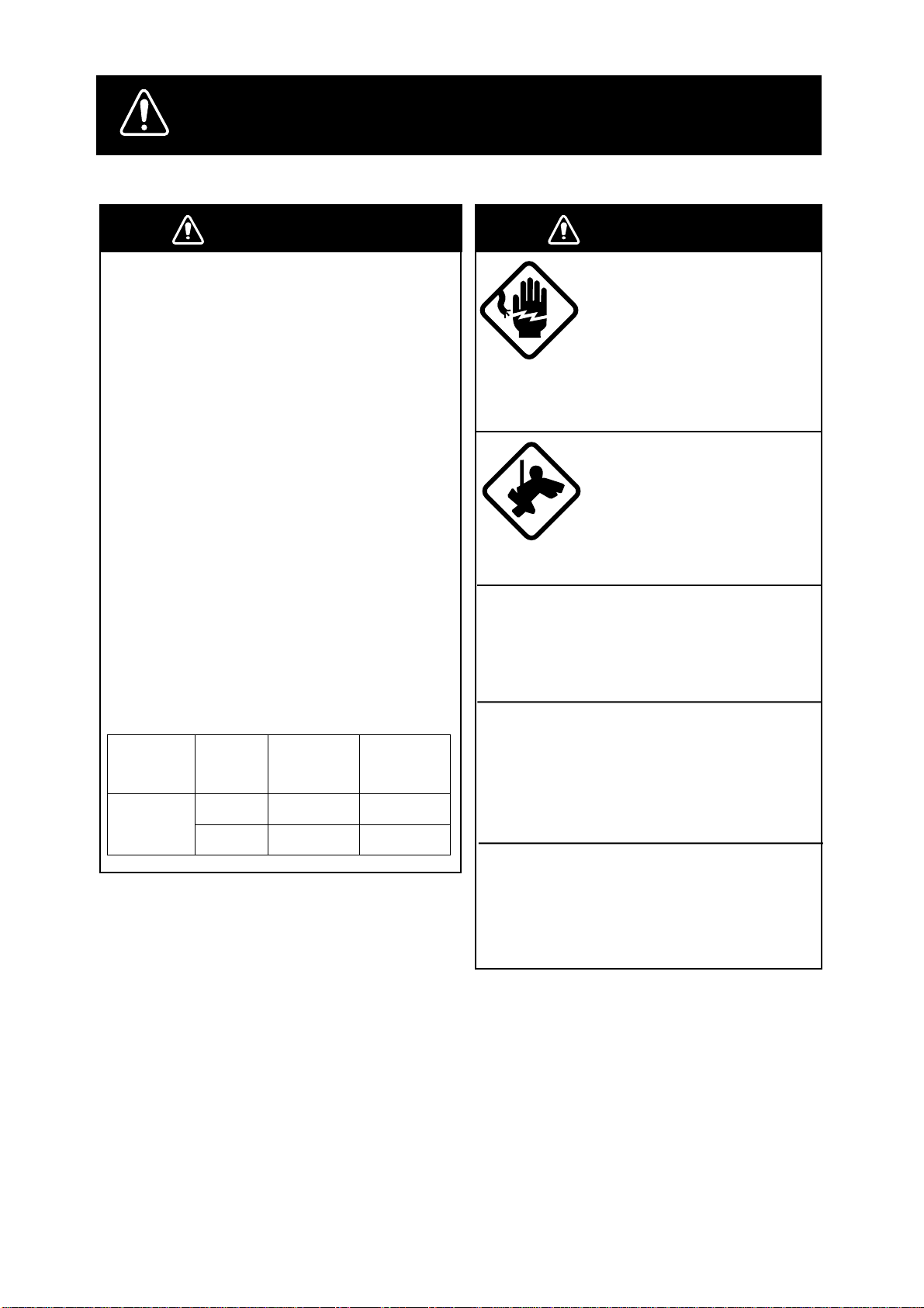
WARNING
Radio Frequency Radiation
Hazard
The radar scanner emits electromagnetic
radio frequency (RF) energy which can be
harmful, particularly to your eyes. Never
look directly into the scanner aperture from
a close distance while the radar is in operation or expose yourself to the transmitting
scanner at a close distance.
Distances at which RF radiation levels of
100 and 10 W/m
table below.
Note: If the scanner unit is installed at a
close distance in front of the wheelhouse,
your administration may require halt of
transmission within a certain sector of
scanner revolution. This is possible Ask
your FURUNO representative or dealer to
provide this feature.
ledoM
5512-RF
2
exist are given in the
rotaidaR
epyt
A4NX– m07.0
A5NX– m06.1
otecnatsiD
2
m/W001
tniop
m/W01
tniop
WARNING
Do not open the equipment
unless totally familiar with
electrical circuits and
service manual.
ELECTRICAL
SHOCK
HAZARD
Construct a suitable service platform
from which to install the scanner unit.
Serious injury or death can result if someone falls from the radar scanner mast.
Turn off the power at the mains switch-
otecnatsiD
2
board before beginning the installation.
Fire, electrical shock or serious injury can
result if the power is left on or is applied
while the equipment is being installed.
Do not install the display unit where it
may get wet from rain or water splash.
Only qualified personnel
should work inside the
equipment.
Wear a safety belt and hard
hat when working on the
scanner unit.
Serious injury or death can
result if someone falls from
the radar scanner mast.
Water in the display unit can result in fire,
electrical shock or equipment damage.
i
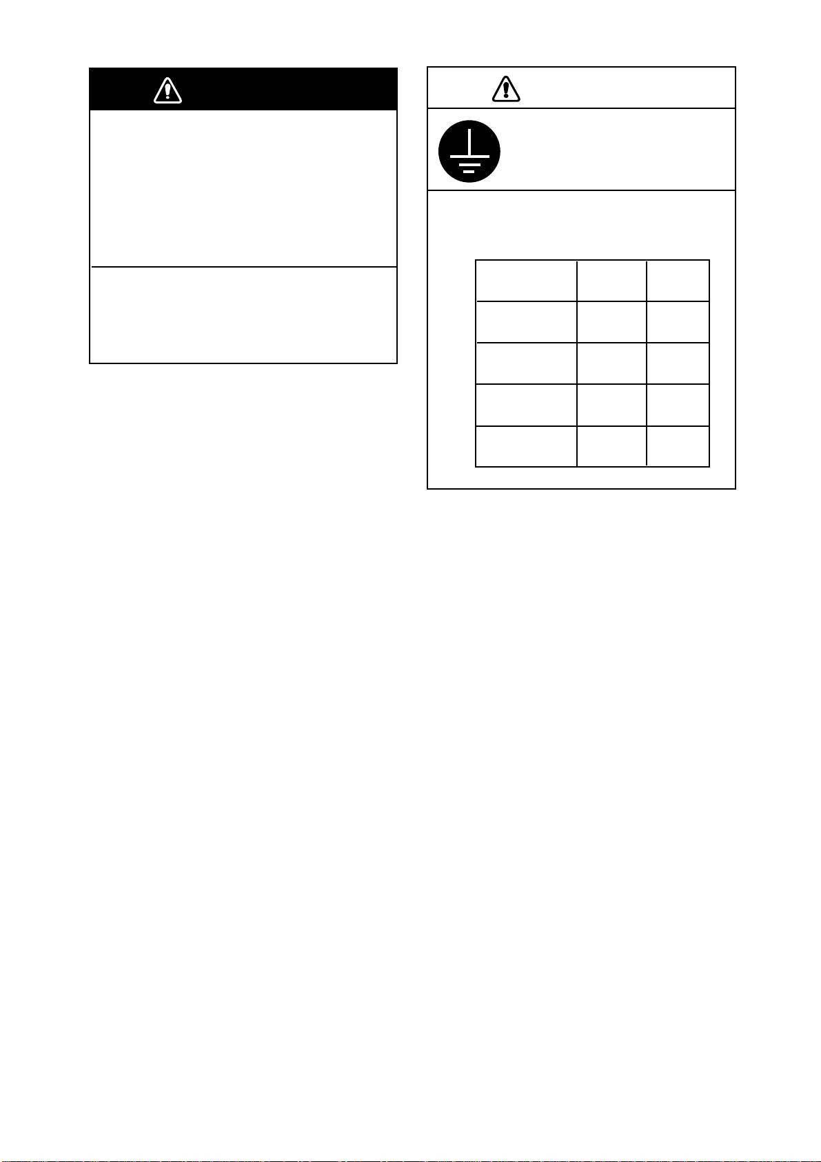
WARNING
CAUTION
Be sure that the power supply is
compatible with the voltage rating of
the equipment.
Connection of an incorrect power supply
can cause fire or equipment damage. The
voltage rating of the equipment appears
on the label above the power connector.
Use only the specified power cable.
Fire or equipment damage can result if a
different cable is used.
Ground the equipment to
prevent electrical shock and
mutual interference.
Observe the following compass safe
distances to prevent deviation of a
magnetic compass:
Standard Steering
compass compass
Display
unit
Scanner
unit
Power Supply
Unit PSU-001
Power Supply
Unit PSU-004
1.70 m 0.90 m
3.90 m 2.30 m
1.20 m 0.90 m
0.50 m 0.30 m
ii

TABLE OF CONTENTS
EQUIPMENT LISTS................................................................................................... iv
SYSTEM CONFIGURATION..................................................................................vi
MOUNTING
1.1 Scanner Unit ............................................................................................................. 1-1
1.2 Display Unit ............................................................................................................... 1-6
1.3 Power Supply Units ................................................................................................. 1-14
WIRING
2.1 Scanner Unit ............................................................................................................. 2-1
2.2 Display Unit ............................................................................................................... 2-5
2.3 Changing AC Power Specification of Display Unit .................................................. 2-10
2.4 Power Supply Units ..................................................................................................2-11
INITIALIZATION AND ADJUSTMENT
3.1 Tuning Initialization.................................................................................................... 3-1
3.2 Accessing Menus for Initialization and Adjustment................................................... 3-1
3.3 Adjusting Video Signal Level..................................................................................... 3-1
3.4 Heading Alignment .................................................................................................... 3-2
3.5 Adjusting Sweep Timing............................................................................................ 3-3
3.6 Suppressing Main Bang ............................................................................................ 3-3
3.7 Confirming Magnetron Heater Voltage ...................................................................... 3-4
3.8 Initial Setting Menus.................................................................................................. 3-6
INSTALLATION OF OPTIONAL EQUIPMENT
4.1 Gyro Converter GC-8 ................................................................................................ 4-1
4.2 ARP Board ARP-26 ................................................................................................... 4-7
4.3 RP Board RP-26...................................................................................................... 4-10
4.4 Performance Monitor PM-30 ................................................................................... 4-14
4.5 Alarm Kit.................................................................................................................. 4-15
PACKING LISTS........................................................................................................A-1
OUTLINE DRAWINGS............................................................................................D-1
INTERCONNECTION DIAGRAM ...................................................................... S-1
SCHEMATIC DIAGRAMS .....................................................................................S-2
iii
Standard Supply
emaNepyT.oNedoCytQskrameR
tinUrennacS
tinUyalpsiD421-PDR–1
ylppuSrewoP
roftinU
tinUrennacS
06-100-USP–
16-100-USP–CAV011
26-100-USP–CAV511
EQUIPMENT LISTS
N-9400-BSR-A4NX–
I-9400-BSR-A4NX–
N-9400-BSR-A5NX–
I-9400-BSR-A5NX–
N-0500-BSR-A4NX–
I-0500-BSR-A4NX–
N-0500-BSR-A5NX–
I-0500-BSR-A5NX–
3 ,φ W051
3 ,φ W051
3 ,φ W051
3 ,φ W051
1
W05
W05
W05
W05
CAV001
tceleS
eno
,CAV022/002,reciedon,mm0752
,CAV022/002,recied/w,mm0752
,CAV022/002,reciedon,mm0123
,CAV022/002,recied/w,mm0123
,CDV42,reciedon,mm0752
,CDV42,recied/w,mm0752
,CDV42,reciedon,mm0123
,CDV42,recied/w,mm0123
tinU
ylppuSrewoP
straPerapS
noitallatsnI
slairetaM
seirosseccA
S-80-07-400-USP–
S-05-2-400-USP–CDV42
)rewopCD(00821-30PS296-780-000
)rewopCA(01821-30PS396-780-000
00591-30PC496-780--000
01591-30PC596-780--000
02591-30PC696-780--000
03591-30PC796-780--000
01560-30PF004-980-000
05560-30PF674-980-000
tceleS
eno
tceleS
eno
tceleS
eno
tes1
A8.0,CAV022/002
tinurennacS:30290-30PS
tinuyalpsiD:30521-30PS
100-USP:20290-30PS
400-USP:02301-30PS
tinuyalpsiD:30521-30PS
100-USP:20290-30PS
400-USP:02301-30PS
tinurennacS:10641-30PC
tinuyalpsiD:30191-30PC
100-USP:61931-30PC
400-USP:70931-30PC
tinuyalpsiD:30191-30PC
100-USP:61931-30PC
400-USP:70931-30PC
tinuyalpsiD:30191-30PC
100-USP:61931-30PC
400-USP:70931-30PC
tinuyalpsiD:30191-30PC
100-USP:61931-30PC
400-USP:70931-30PC
30560-30PF
,30560-30PF
S
E
)m51(51-08-30S:elbaclangiS
E
tinurennacS:10641-30PC
P
A
C
K
)m02(51-08-30SelbaclangiS
tinurennacS:10641-30PC
tinurennacS:10641-30PC
,20560-30PF,10260-30PF
,20560-30PF,10260-30PF
I
N
G
L
)m03(51-08-30S:elbaclangiS
I
S
T
S
)m06(51-08-30S:elbaclangiS
.scp4,01-CB-03-PCpaccitemsoC
iv

Optional Equipment
emaNepyT.oNedoCytQskrameR
yalpsiDetomeR0108-DMF – 1
retrevnoCoryG
hctiwsretnI7-JR – 1
hctiwsretnI8-JR – 1
rotinoMecnamrofreP03-MP – 1
remrofsnarT
tinU
tiKnoitallatsnIMP051-30PO094-584-800tes103-MProF
APRA62-PRA005-584-800tes1
rettolPoediV
2-8-CG025-644-800
1-8-CG072-644-800nitliuB
3965-UR654-030-0001
3081-UR794-030-0001
2256-UR014-030-0001
5033-UR844-030-0001reciedroF
1-6645-UR354-030-0001
3243-UR344-030-0001
8571-UR614-030-0001
T-62-PR015-584-800
Z-62-PR025-584-800daehlortnocetarapesroF
tes1
redroetarapeS
V011 → ,V022
tinurennacsrof
V044 → ,V001
tinuyalpsidrof
V022 → ,V002
tinurennacsrof
V044 → ,V002
tinurennacsrof
CA → ,V42CD
tinurennacsrof
V022 → V044
100-USPtinuylppusrewoprof
epytelosnoc,potelbaT
tes1
tiKgnitnuoM
daeHlortnoCetarapeS
elbaCrewoP
tiKmralA651-30PO056-005-8001
151-30PO035-584-8001
S-VVC
m51-)C2x8(
436-065-0001 tinuyalpsid.cepsCDroF
v
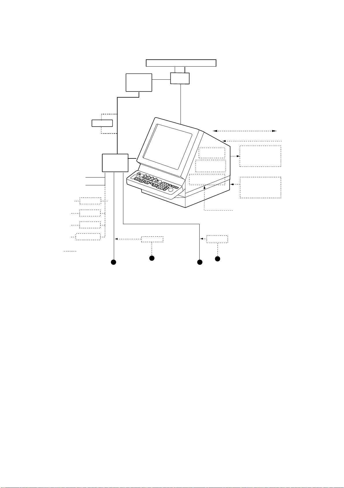
SYSTEM CONFIGURATION
SCANNER UNIT
POWER SUPPLY UNIT
PSU-001
For 220/230 VAC
only
POWER SUPPLY
UNIT PSU-004
24 VDC
200/220 VAC, 3φ,
50/60 Hz
100/110/115/220
230 VAC, 1φ, 50/60 Hz
110 VAC, 3φ,
60 Hz
220 VAC, 3φ,
50 Hz
440 VAC, 3φ,
50 Hz
RU-3423
RU-5693
RU-6522
RU-5466-1
OPTION
SHIP’S MAINS
RU-1758
For SCANNER UNIT
For DISPLAY UNIT
100/110/115/
220/230 VAC
1φ, 50/60 Hz
For DE-ICER
RU-1803
440 VAC
1φ, 50/60 Hz
XN-4A/XN-5A
DISPLAY UNIT
RDP-124
IEC 61162-1 (Input/Output)
ARPA Board
ARP-26
Video Plotter
RP-26
Gyro Converter
GC-8
RU-3305
100 VAC
1φ, 50/60 Hz
IEC 61162-1 (Input)
Navigator
Speed Log
Slave Display
FMD-8010
Performance
Monitor
PM-30
Gyrocompass
110/115/220 VAC
1φ, 50/60 Hz
I/O Data Sentences
Input: GGA, RMA, RMB, RMC, GLL, ZDA,VBW , VHW , VTG, MWV, VWT , VWR, VDR,
DPT, DBT, DBS, MTW, BWR, BWC, WPL, RTE
Output: RAOSD, RARSD, RATTM
vi

1.1 Scanner Unit
Mounting considerations
• The scanner unit is generally installed either on top of the wheelhouse or on the
radar mast, on a suitable platform. Locate the scanner unit where there is a
good all-round view.
• No funnel, mast or derrick should be within the vertical beamwidth of the scanner in the bow direction, especially zero degrees ±5°, to prevent blind sectors
and false echoes on the radar picture.
• It is rarely possible to place the scanner unit where a completely clear view in
all directions is available. Thus, you should determine the angular width and
relative bearing of any shadow sectors for their influence on the radar at the
first opportunity after fitting.
• Locate the antenna of a direction finder clear of the scanner unit to prevent
interference to the direction finder. A separation of more than two meters is
recommended.
MOUNTING
• T o lessen the chance of picking up electrical interference, avoid where possible
routing the signal cable near other onboard electrical equipment. Also avoid
running the cable in parallel with power cables.
• A magnetic compass will be affected if placed too close to the scanner unit.
Observe the following minimum compass safe distances to prevent deviation
of a magnetic compass: Standard compass, 3.90 m, Steering compass, 2.30
m.
• Do not paint the radiator aperture, to ensure proper emission of the radar waves.
• The signal cable run between the scanner and the display is available in lengths
of 15 m (standard), 20 m, 30 m and 60 m. Whatever length is used it must be
unbroken; namely, no splicing allowed.
• Deposits and fumes from a funnel or other exhaust vent can adversely affect
the aerial performance and hot gases may distort the radiator portion. The scanner unit must not be mounted where the temperature is more than 70°C.
• The scanner base is made of cast aluminum. To prevent electrolytic corrosion
of the scanner base, use the seal washers and corrosion-proof rubber mat and
ground the unit with the ground wire (supplied).
• Leave sufficient space around the unit for maintenance and servicing. See the
scanner unit outline drawing for recommended maintenance space.
1-1
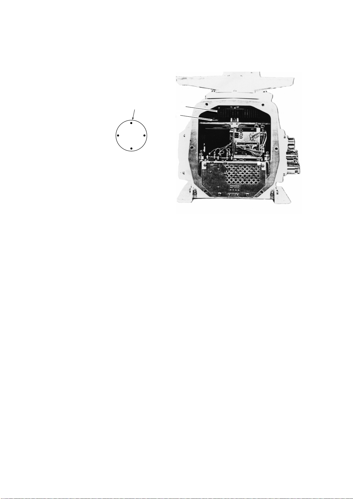
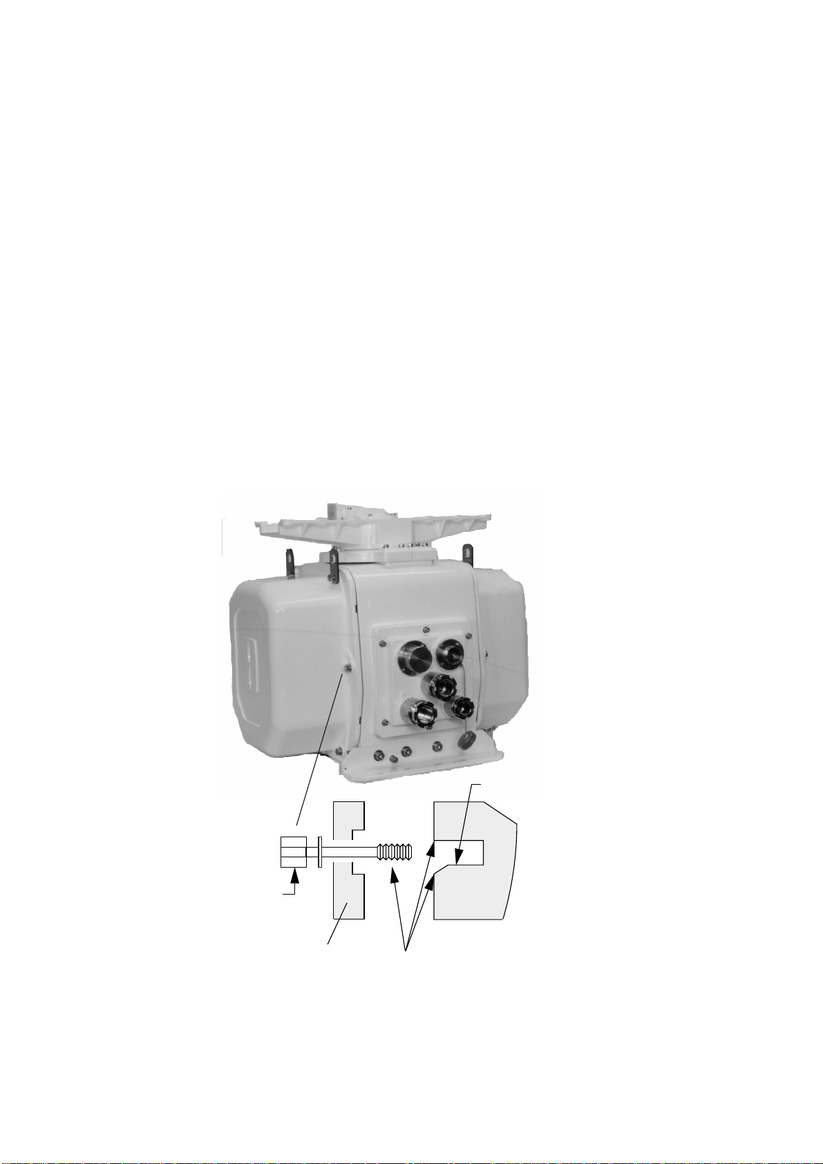
• The scanner unit is normally mounted with the gland side (cable entry side)
facing the ship’s stern. If this direction is not possible, the gland orientation can
be changed in increments of 90°. In this case, the synchronous gear magnet,
which produces the heading signal, should be remounted. Fix the magnet according to scanner unit orientation.
Synchronous gear
Reed switch
C
SHIP’S BOW f
A
D
B
Magnet fixing
holes A, B, C, D
Figure 1-1 Remounting the synchronous gear magnet
Photo No.2880
1-2
Scanner unit assembling
The scanner radiator and the scanner housing are shipped in separate packages
and must be assembled at installation. Assemble them as below. Refer to the
scanner unit assembling drawing at the back of this manual for details.
1. Remove two protective caps from the radiator flange and rotary joint flange.
2. Grease an O-ring and place it in the groove of the rotary joint flange. Make sure
the O-ring is not pinched during assembling.
3. Secure the feeder waveguide to the rotary joint flange with four M6x16 hex
bolts.
4. Fix the feeder waveguide on the radiator joint with four M4x16 washer head
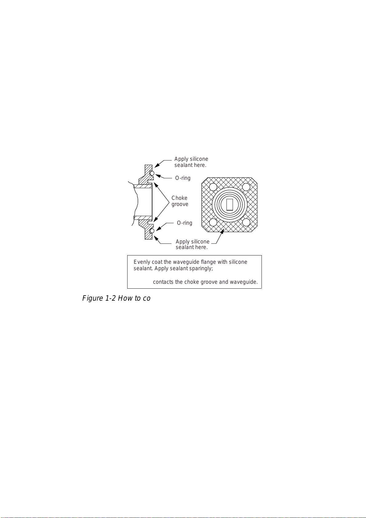
bolts. Coat waveguide flange with silicone sealant as illustrated below.
Apply silicone
sealant here.
O-ring
Choke
groove
O-ring
Apply silicone
sealant here.
Evenly coat the waveguide flange with silicone
sealant. Apply sealant sparingly; it leaks out slightly
when the fixing bolts are tightened. Be sure no
sealant contacts the choke groove and waveguide.
Figure 1-2 How to coat waveguide flange with silicone sealant
5. Loosely fix the radiator to the radiator bracket with M8x25 and M8x30 hex head
bolts, M8 flat washers, M8 spring washers, and M8 hex nuts.
6. Grease the other O-ring and place it in the groove of the radiator flange. Secure
the feeder waveguide to the radiator flange with M4x16 washer head bolts.
7. Fix the feeder waveguide to the bottom of the radiator with the waveguide clamp,
waveguide packing, M4x30 hex head bolts, M4 flat washers, and M4 spring
washers.
8. Tighten bolts loosely fixed at step 5.
1-3
Scanner unit mounting
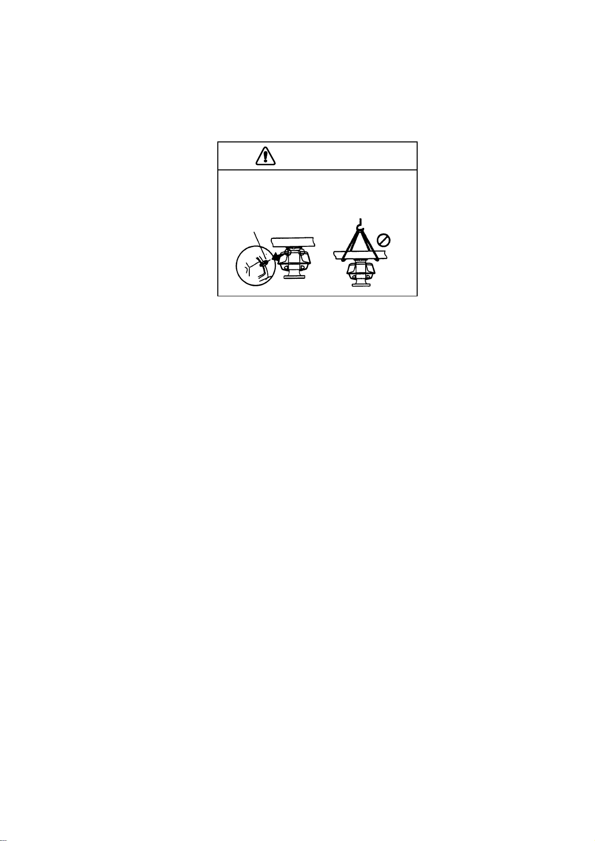
The scanner unit should be assembled before hoisting it to the mounting platform.
When using a crane or hoist, lift the unit by the hoist rings which should be fastened to the bolt fixing covers of the scanner housing. Do not lift it by the scanner
radiator.
CAUTION
DO NOT lift the scanner unit by the radiator;
lift it by the hoist rings. (Be sure to remove
rings after lifting the scanner.)
Hoist
ring
NO!
1. Construct a suitable mounting platform referring to the outline drawing at the
back of the manual.
2. Drill four mounting holes of 15 mm diameter and one cable entry hole of about
50 mm diameter in the mounting platform.
3. Lay the rubber mat (supplied) on the mounting platform.
4. Place the scanner unit on the rubber mat orienting the unit so the bow mark on
its base is facing the ship’s bow.
5. Fasten the scanner unit to the mounting platform with M12x60 hex bolts, nuts,
flat washers and seal washers.
6. Using hex bolt (M6x25), nut (M6) and flat washer (M6) establish the ground
system on the mounting platform as shown in Figure 1-3. Connect the ground
wire (RW-4747, 340 mm, supplied) between the grounding point and ground
terminal on the scanner unit. Coat the entire ground system with silicone sealant (supplied).
1-4
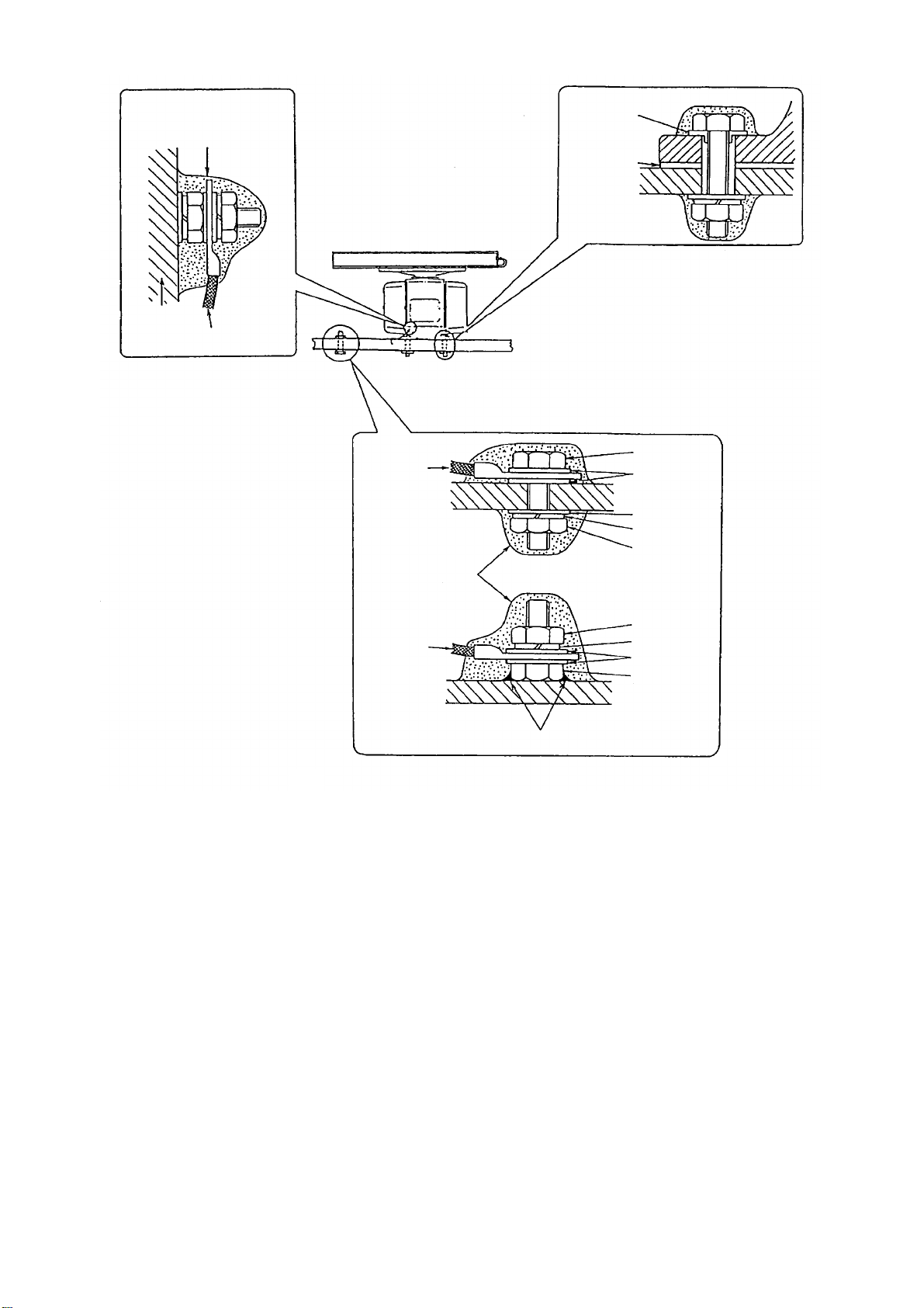
Coat with anticorrosive
sealant after connecting
ground wire.
Ground wire
Ground terminal is prefitted
on scanner chassis.
Seal washer
Corrosionproof rubber
mat
Set seal washer and corrosion-proof
rubber mat; coat with anticorrosive
sealant.
Ground
wire
OR
Ground
wire
Arrange ground terminal at nearest ground spot.
Figure 1-3 Mounting of scanner unit
Hex bolt
Flat washer
Flat washer
Spring washer
Hex nut
Hex nut
Spring washer
Flat washer
Hex bolt
1-5
1.2 Display Unit
Before mounting the display unit
If Gyro Converter GC-8 (option) is to be used, install and setup the GYRO CONVERTER Board before mounting the display unit, because of the difficulty involved
in doing it after the display unit is installed. Instructions for installation and setup
are in Chapter 4.
Mounting considerations
When selecting a mounting location, keep in mind the following points:
• Select a location where the display unit can be viewed and operated conveniently and where the screen can be viewed while facing towards the bow.
• Locate the unit out of direct sunlight and away from heat sources because of
heat that can build up inside the cabinet.
• Locate the equipment away from places subject to water splash and rain.
• The display unit is very heavy. Be sure the mounting location is strong enough
to support the weight of the unit under the continued vibration which is normally
experienced on the ship. If necessary reinforce the mounting location.
• Determine the mounting location considering the length of the signal cable between the scanner unit and the display unit and the power cable between the
display unit and Power Supply Unit PSU-004.
• Leave sufficient space on the sides and rear of the unit to facilitate maintenance. Also, leave a foot or so of “service loop” in cables behind the unit so it
can be pulled forward for servicing or easy removal of connectors.
• A magnetic compass will be affected if placed too close to the display unit.
Observe the following compass safe distances to prevent deviation of a magnetic compass: Standard compass, 1.70 m, Steering compass, 0.90 m.
Mounting procedure
Tabletop mounting
This procedure requires two people
to complete.
1. Make four holes of 12 mm diameter in the mounting location
referring to the outline drawing
at the end of this manual.
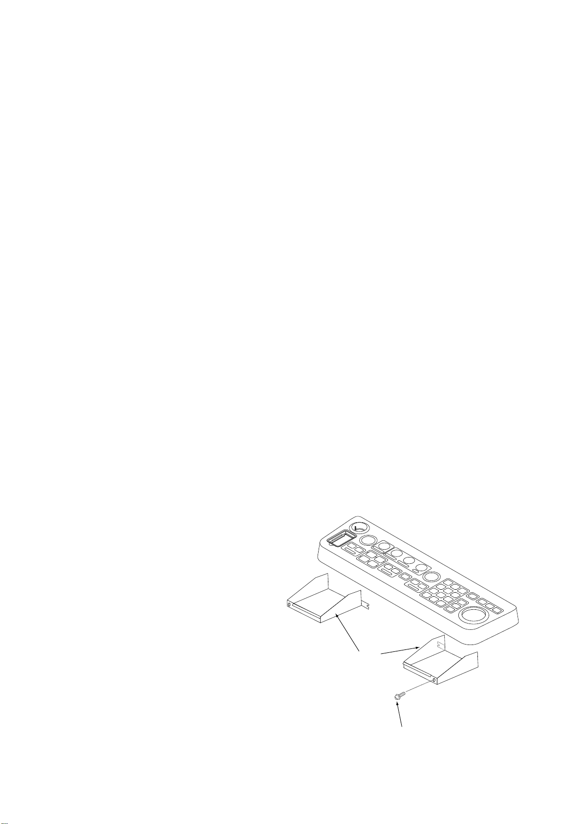
Left, right
arm cover
2. Unfasten the screws fixing the
right and left brackets on the
control head.
3. Unfasten bolts (four total) in the
brackets.
M4x10
Figure 1-4 Control head
1-6
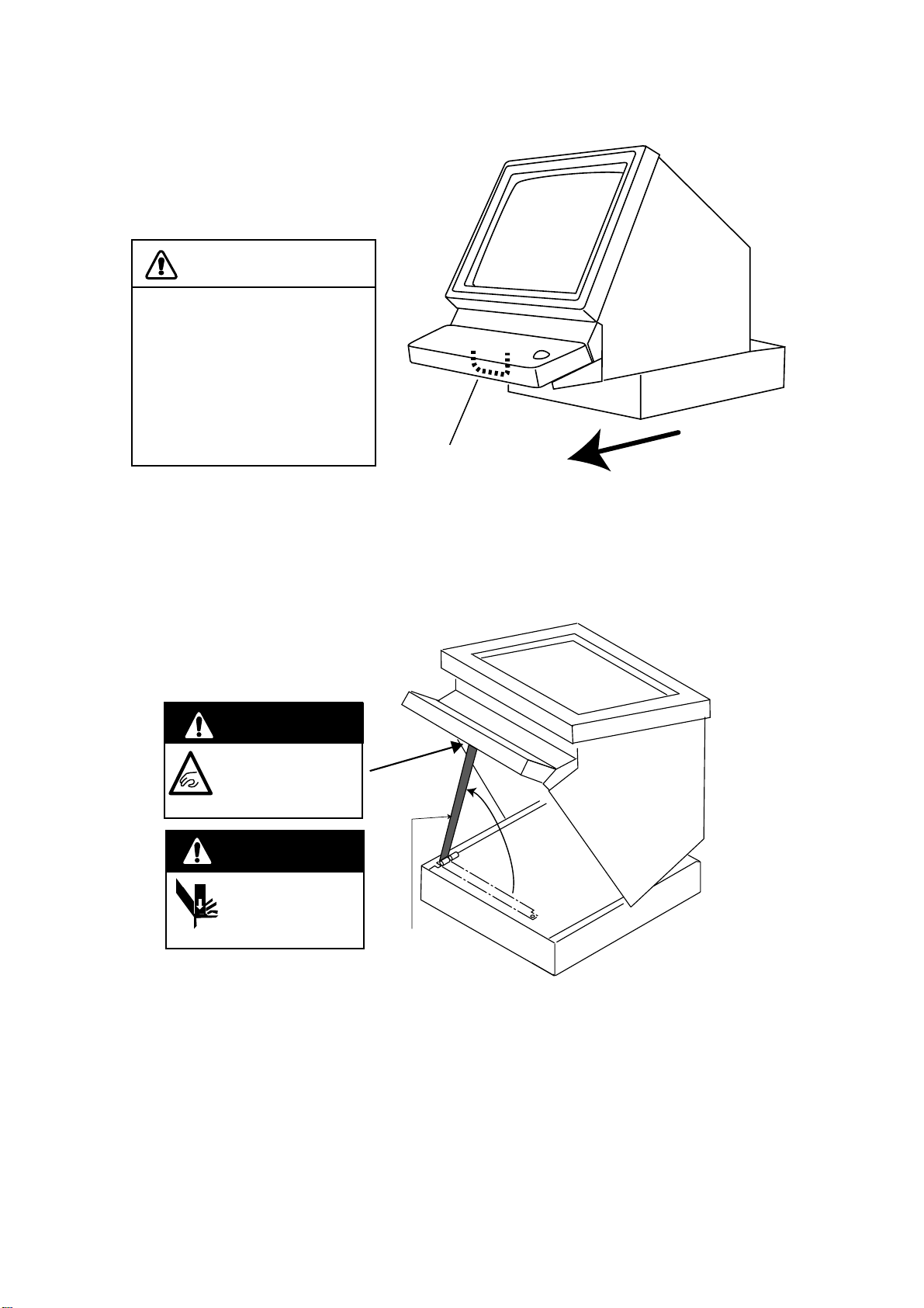
4. While one person is holding the mounting base at the sides, pull the handle on
the underside of the control head to draw the display unit toward you until you
hear a click.
CAUTION
Use two people to complete
this step.
The display unit may fall to
the deck when it is pulled
forward, since the mounting
base is not yet fastened to
the mounting location.
Handle
Figure 1-5 Display unit
Pull forward
5. This step requires two people to complete. While raising the monitor until the
CRT is horizontal, fix the stay as follows:
a)Raise the stay as shown below.
Two warning labels on
the underside of monitor
HORIZONTAL
WARNING
Possibility of injury.
Hold handle when
mounting display unit.
WARNING
Display unit may fall.
Lock stay before
servicing.
Stay
Figure 1-6 Display unit, inside view
1-7
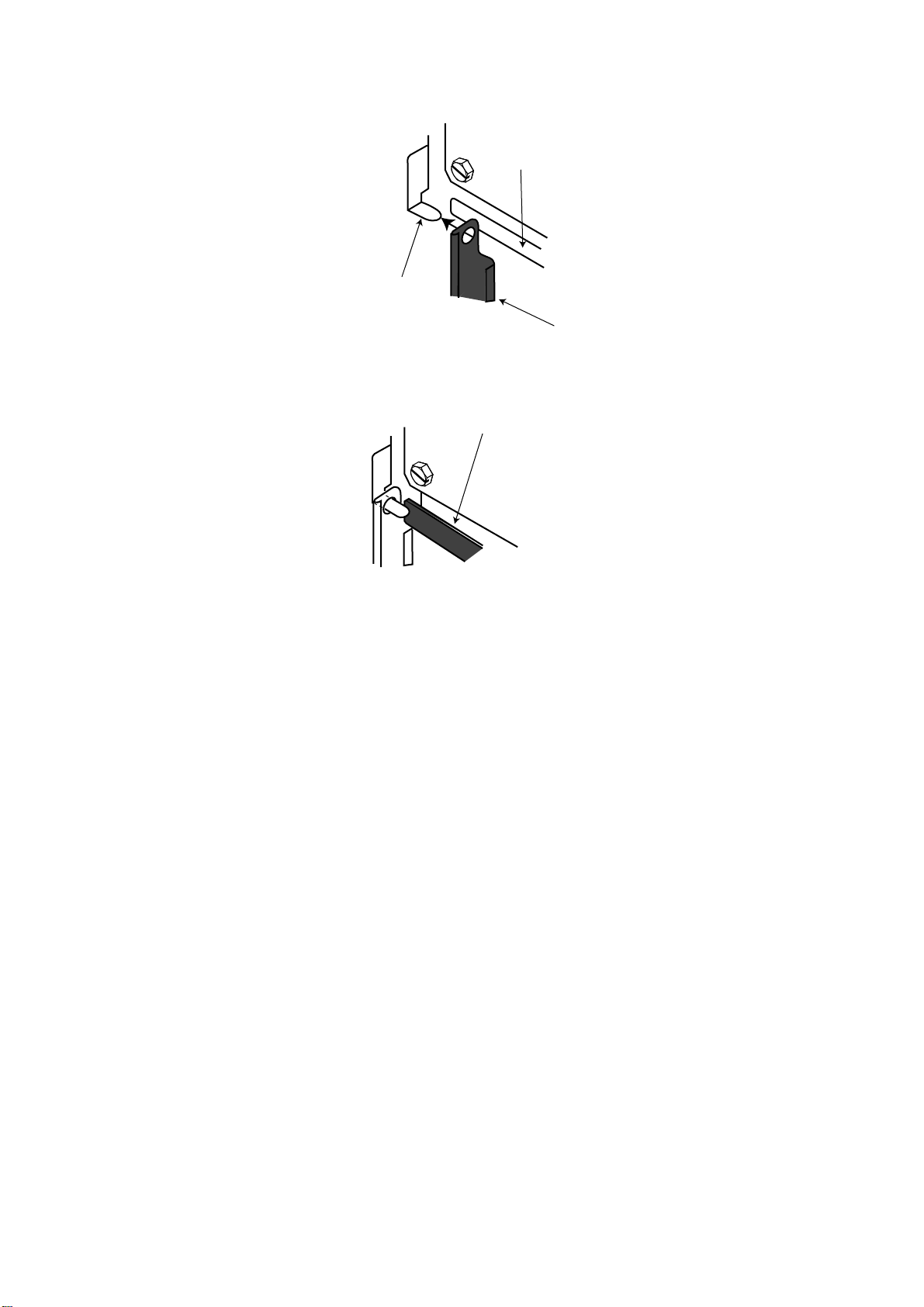
b)While pushing the stopper , set the catch on the display unit in the hole at the
front edge of the stay.
Stopper
Catch
Stay
Figure 1-7 Setting catch to hole in stay
c)Release hand from stopper.
Release stopper;
fix stay.
Figure 1-8 Stay fixed
6. Fasten the display unit to the mounting location at front fixing holes (2 points)
with M10 bolts, nuts and flat washers, using the pipe box spanner (supplied).
You cannot fasten the display unit at the rear fixing holes while the monitor is
raised.
7. Retract the stay and lower the monitor.
8. Fasten the display unit to the mounting locations at rear fixing holes (2 points)
with M10 bolts, nuts and flat washers, using the pipe box spanner (supplied).
The rear left hole is hid under the PTU cover. Remove the cover as follows:
(1) Unfasten five M3x8 screws at the top of the PTU cover and two M4x8
screws at the front of the cover to slide the cover toward the front side.
(2) Remove the cover by grasping the knob on the top of the cover.
1-8
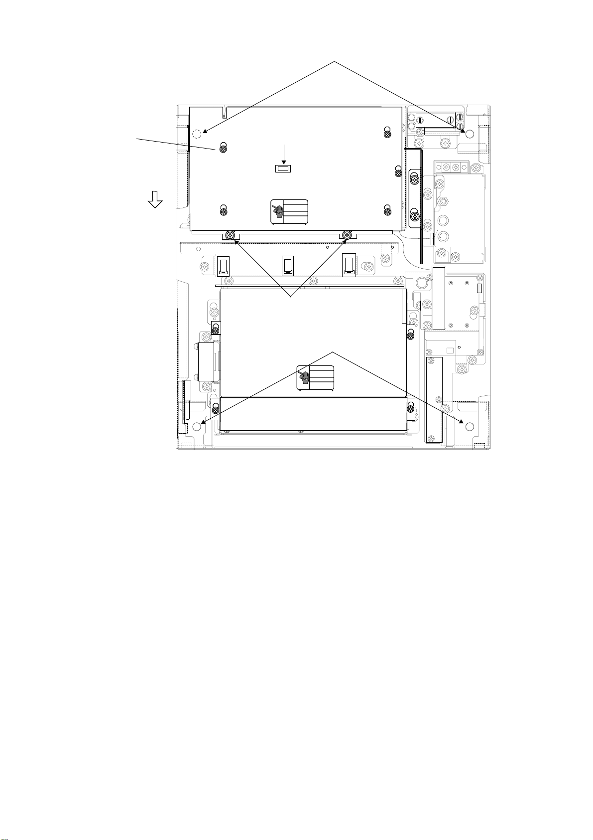
Fixing hole (rear)
*Screw
(M3x8, 5 pcs.)
Slide forward.
*
J105
J104
J103
Knob
Screw (M4x8, 2 pcs.)
Fixing hole (front)
J466
J462
J465
*
*
*
Figure 1-9 How to remove the PTU cover
9. Push the monitor forward until you hear a click.
10.Fix the brackets with the M10 bolts removed at step 3.
Console type mounting
1. Make six holes of 15 mm diameter and a cable entrance hole through the deck
referring to the outline drawing at end of this manual.
2. Open the front cover.
3. Fix the equipment with M12 bolts, nuts and washers.
4. Hoist the console to the deck by using the eye bolts attached to the console.
Remove the eye bolts and set the cosmetic caps with washers to the eye bolt
holes.
Separating the control head
The control head connects to the display unit with a connection cable, thus it can
be located where desired, using the separate control head kit (option). Follow the
procedure on the next page to separate the control head from the display unit.
1-9
Separate Control Head Kit (Type: OP03-151, No.: 008-485-530)
emaNepyTytQ.oNedoCskrameR
.yssAelbaCP1/P02BS642LU1218-041-0002249S30,m01
eldnaH4-C-2401-A1689-008-000
teeFrebbuR3005-JS4787-108-000epat/W
tnorFrotinoM
revoC
etalPgnixiFBK1961-441-301049-362-001
etalPelodnaH2361-441-301040-862-001
1631-441-301043-362-001
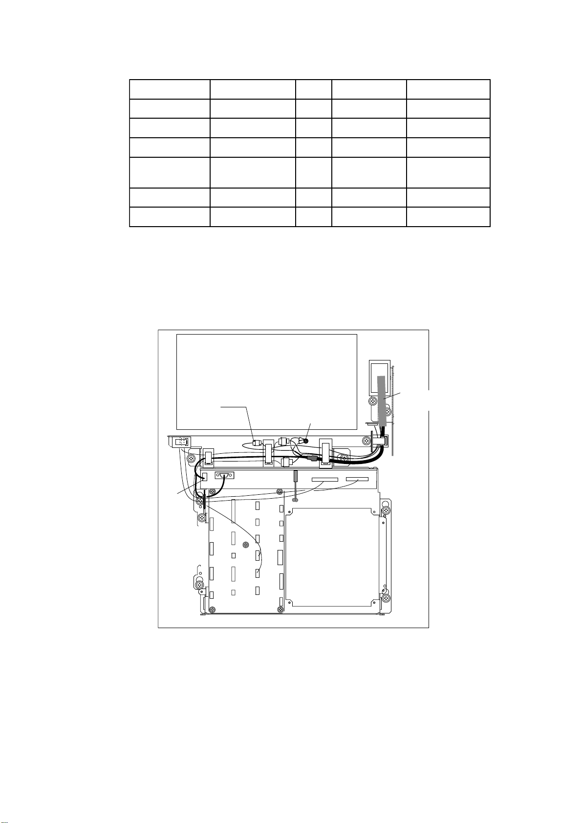
Display unit modification procedure
1. Raise the monitor unit following to procedure for tabletop mounting on page 1-
6.
2. Unplug two connectors from the control head cable (P412 from MOTHER Board
and J583) and unfasten two earth wires.
PTU COVER
J583
Earth Wire
Control Head
Cable
J418
MB 03P9251
P412
INT
03P9252
Figure 1-13 Display unit, inside view
3. Lower the monitor.
4. Unfasten the M4 screw fixing the ground terminal of the connection cable.
5. Push the monitor forward until you hear a click.
6. Unscrew four screws fixing the top cover of the display unit.
7. Remove three clamps fixing the connection cable in the monitor unit.
1-10
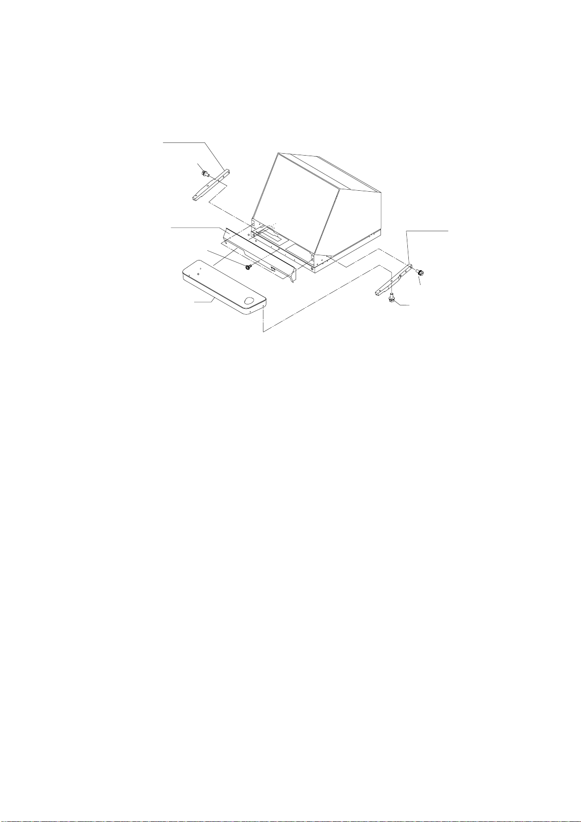
8. Unfasten four screws fixing the right and left brackets on the control head.
9. Unfasten four screws fixing the right and left covers on the display unit.
10.Unfasten six screws fixing the right and left KB arms.
11.Unfasten three screws fixing the panel cover.
KB arm (L)
03-144-1341
M5X25 SUS 3 pcs.
•
Panel cover
03-144-1345
M4X10, 3 pcs.
Control head
KB arm (R)
03-144-1342
M5X25 SUS 3 pcs.
M5X25 SUS 4 pcs.
Figure 1-14 Removing the control head
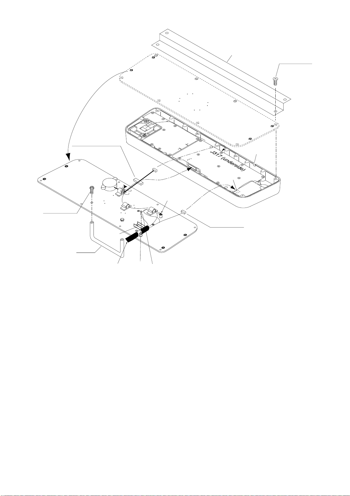
Control head modification procedure
1. Unfasten eight screws (M4X8) on the underside of the control head. Unplug
connectors P314, P312 and P317 from the control head. Separate the KB bottom plate from the control head.
2. Unfasten the screw (M4) fixing the ground terminal and two screws (M4X8)
fixing the clamp. Remove the connection cable assy.
3. Unfasten two screws (M6X12) from the inside of the bottom plate of the control
head to dismount the handle.
4. Replace the cable assy. with cable assy. UL2464SB2-0P/1P (10 m, supplied)
as below and reassemble the control head.
1-11
P312 FX Connector
KB BOTTOM
PLATE
Upset Screw
M6X12 (2 pcs.)
Earth Wire
J314 (underside)
J312 (underside)
P314 XH3P
KB Fixing Plate
Screw
M4X8 (8 pcs.)
Lay cable in slot.
KB Clamp
Handle
Replace with
cable assy. in
kit.
Spacer
Pan-head Screw M4X8 (2 pcs.)
Be careful not to pinch cable between
KB clamp and spacer.
Figure 1-15 Control head
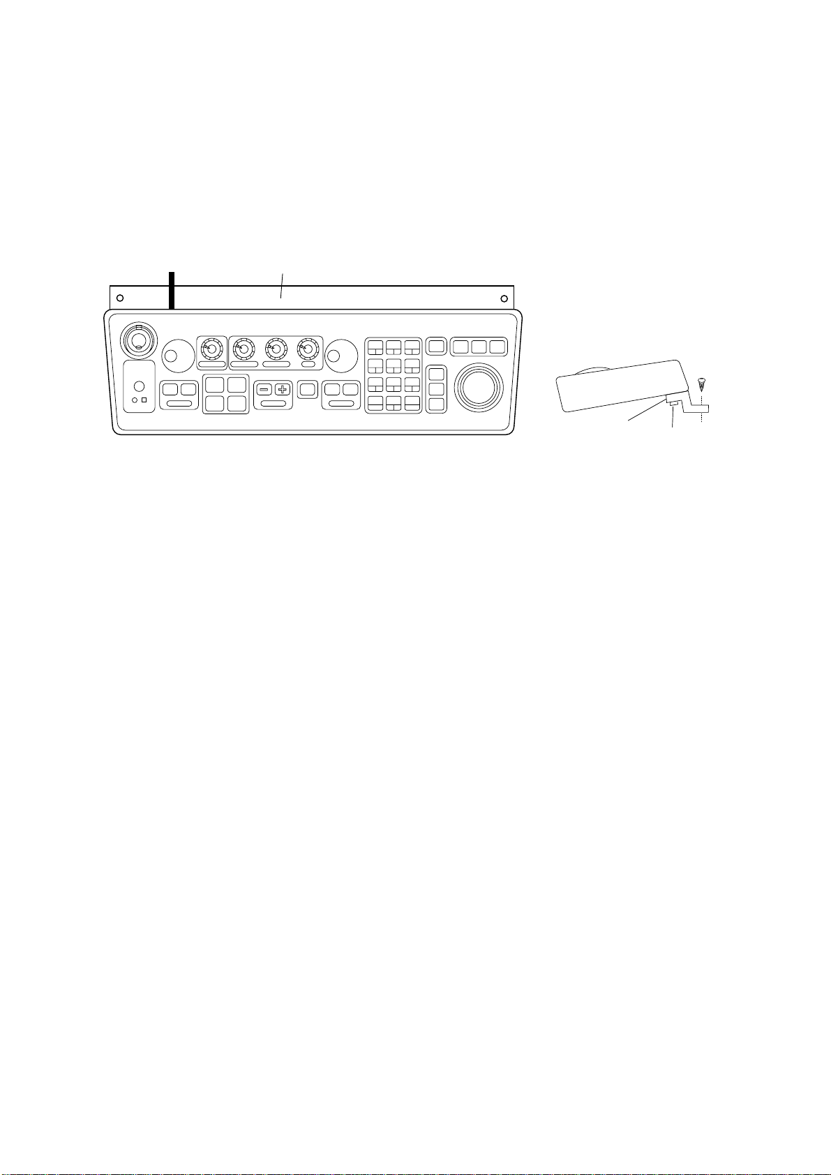
Connection of display unit to control head
1. Attach the handle to the handle plate, using the screws for the handle and
bottom cover of the control head.
2. Attach the handle plate to location where the KB arms were fastened.
3. Pull the monitor toward you until you hear click.
4. Lead in the cable assy. (option) from the rear entrance of the display unit. See
Chapter 2.
5. Raise the monitor and fix the stay.
6. Inside the display unit, fasten ground wire of the cable assembly with an M4
screw on the chassis.
7. Plug in two connectors of connection cable (P412, J583: See illustration on the
previous page.)
1-12
8. Lower the monitor.
9. Attach the monitor front cover (option) to the place the panel cover have been,
using the screw for the panel cover.
10.Attach rubber to feet to the bottom of the keyboard if the keyboard is not going
to be permanently fixed. To fix the keyboard to a desired location, fasten the KB
fixing plate to the keyboard and desired location with two upset screws (M5X25,
formerly used to fasten KB arms) and two tapping screws (φ6.5, local supply)
as below.
KB Fixing Plate
CONTROL HEAD
SIDE VIEW
KB Fixing
Plate
CONTROL HEAD TOP VIEW
φ6.5
Tapping
Screw
M5X25
Upset
Screw
Figure 1-15 How to attach KB fixing plate
11.Set dust cover KB (supplied) on the control head.
Attachment of hood
1. Set two spacers (supplied) to the lower two of the four M5 holes in the CRT
panel.
2. Screw two screws (supplied) into the holes in the hood.
3. Set the bottom of the hood to the screws at the bottom of the CRT panel, and
then fasten the two screws at the top of the hood to the CRT panel.
1-13

1.3 Power Supply Units
The Power Supply Unit PSU-001 (for scanner unit) and PSU-004 (for display unit)
do not contain usual operating controls. Therefore, they can be installed in any
recessed place either in vertical or horizontal position. (For the console mount
display unit, the PSU-004 may be installed inside the console.) However, select a
dry and well-ventilated location and observe the minimum compass safe distances
below to prevent deviation of a magnetic compass.
dradnatS
ssapmoc
100-USP
)tinurennacsrof(
400-USP
)tinuyalpsidrof(
m02.1m09.0
m05.0m03.0
gnireetS
ssapmoc
1-14
2.1 Scanner Unit
Preparations
Open the port side cover of the scanner unit to access terminal boards.
Fabricating signal cable S03-80
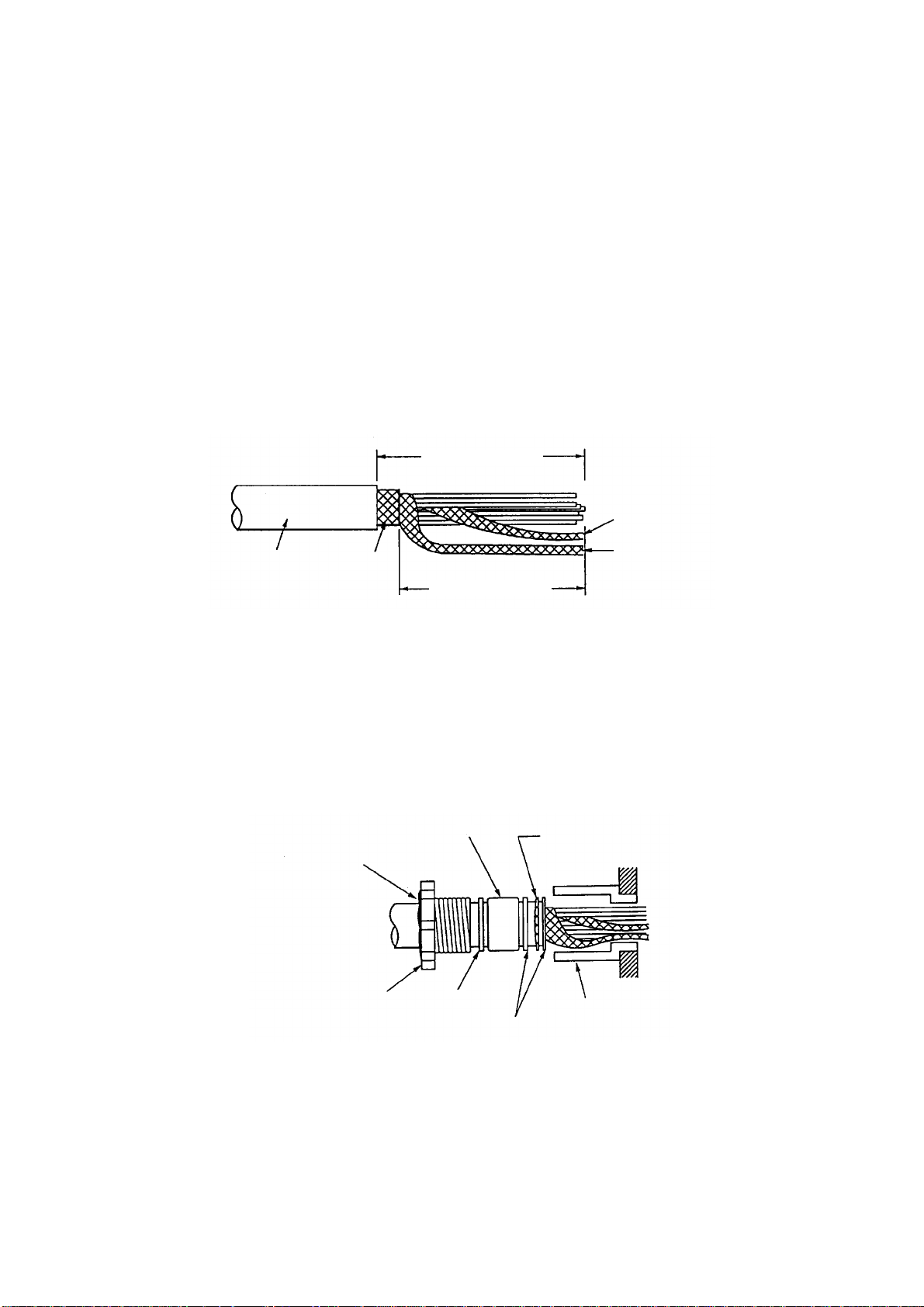
1. Shorten the cable, extending the length actually required by 800 mm. Strip off
about 600 mm of the anti-corrosive vinyl sheath, and 790 mm of the armor
and the inner vinyl sheath, being careful not to nick the braided shield.
WIRING
Approx. 800 mm
Inner shield
Anti-corrosive
vinyl sheath
Armor
Approx. 790 mm
Outer shield
Figure 2-1 Fabricating the signal cable S03-80
2. Unravel the outer shield with a screwdriver or similar tool to expose the cores
beneath the outer shield.
3. Similar to step 2, expose the cores beneath the inner shield. Mark all cores
for future identification.
4. Slide the clamping gland, washers and gasket onto the cable. (Use lower side
gland.)
Seal with putty
after tightening.
Clamping gland
Gasket
Washer
Armor
Gland body
Washer
Figure 2-2 Passing clamping gland, washers and gasket on signal cable
5. Ground the armor through the two washers as shown above. Trim the shields
considering their location on the earth terminal inside the scanner unit. Fit a
crimp-on lug (yellow, FV5.5-4, ø4) to inner and outer shields, then connect
them to the ground terminal inside the scanner unit.
2-1
6. Determine the length of each core considering its location on STB-1 in the
scanner unit (see the interconnection diagram on page S-1). Remove approx.
6 mm of the vinyl insulation from the end of each core and fix the crimp-on lug
FV1.25-M3 (Red) to each core.
STB-3
STB-1
Photo No.2872
STB-2
Figure 2-3 Scanner unit, cover opened
7. Remove the outer sheath of the coaxial cable (2C-2V) by 75 mm. Pull back
the braided shield to expose the inner core. Remove approx. 25 mm of insulator from the end of inner core and fold back conductor as illustrated below .
Shorten the shield leaving approx. 45 mm. Fit crimp-on lugs to the conductor
(FVD1.25-3, Red) and braided shield (FV1.25-M3, Red).
50 mm
75 mm
Crimp-on lug
FV1.25-M3
(Red, ∅3)
Fold back the conductor
as illustrated below.
Crimp-on lug
FVD1.25-3
(Red, ∅3)
Inner core
Conductor
6 mm
Coaxial cable
2C-2V
45 mm
Figure 2-4 Fabrication of coaxial cable
8. Slip the cable gland over the cable and tighten the cable gland nut. Seal the
cable gland nut with putty to preserve watertight integrity.
9. Connect wiring to terminal STB-1 referring to the interconnection diagram.
2-2
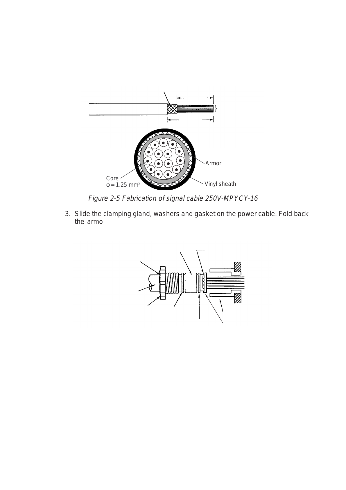
Fabricating signal cable 250V-MPYCY-16 (JIS cable)
A
1. Unfasten the clamping gland from the upper cable gland, and remove the
gasket and flat washers.
2. Shorten the cable as appropriate. Remove the vinyl sheath by 600 mm. Remove the armor by 590 mm.
rmor
790 mm
Conductors
800 mm
Armor
Core
φ = 1.25 mm
2
Vinyl sheath
Figure 2-5 Fabrication of signal cable 250V-MPYCY-16
3. Slide the clamping gland, washers and gasket on the power cable. Fold back
the armor by 5 mm, then put it between washer and cable gland body as
below.
Gasket
Seal with putty
after tightening.
Vinyl sheath
Clamping gland
Flat
washer
Armor (folded back)
Cable gland
Flat
washer
Flat
washer
Figure 2-6 Passing clamping gland, washers and gasket on the signal cable
4. Determine the length of the cores considering their location on STB-2 and
STB-3. Trim conductors as necessary.
5. Ground the armor by inserting it through the two flat washers near the cable
gland.
6. Remove the sheath of each core by 6 mm. Fix crimp-on lugs (FV1.25-4, blue,
ø4) to each conductor. Make sure each connection is secure both electrically
and mechanically.
2-3
7. Secure the clamping gland to the cable gland body; then seal with putty.
8. Connect the conductors to STB-2 and STB-3, referring to the interconnection
diagram on page S-1.
9. Check for loose screws, poor contact on crimp-on lugs, etc. Close the terminal boards.
When the de-icer is installed
1) Before beginning any work on the scanner unit, turn off the breaker for the deicer line at the main switchboard to remove the power (100 VAC, 1ø) to the
de-icer. (Turning off the power to the display unit has no effect.)
2) The neck of the scanner unit becomes VERY HOT when the de-icer is working. (The de-icer turns on when ambient temperature is below 0°C.)
Fixing the scanner cover
Before closing the cover check for loose screws and poor contact on crimp-on
lugs. Grease fixing bolts for cover, gasket and tap holes in scanner chassis.
Attach cover .
Fixing
bolt (12 pcs.)
Scanner cover
Figure 2-7 Scanner unit, side view
Photo No.2871
Tap hole
SCANNER
CHASSIS
Apply silicone
grease here.
2-4
2.2 Display Unit
Two cables are terminated at the display unit: the signal cable S03-80 and the
power supply cable from the Power Supply Unit PSU-004.
Fabricate the power cable as below.
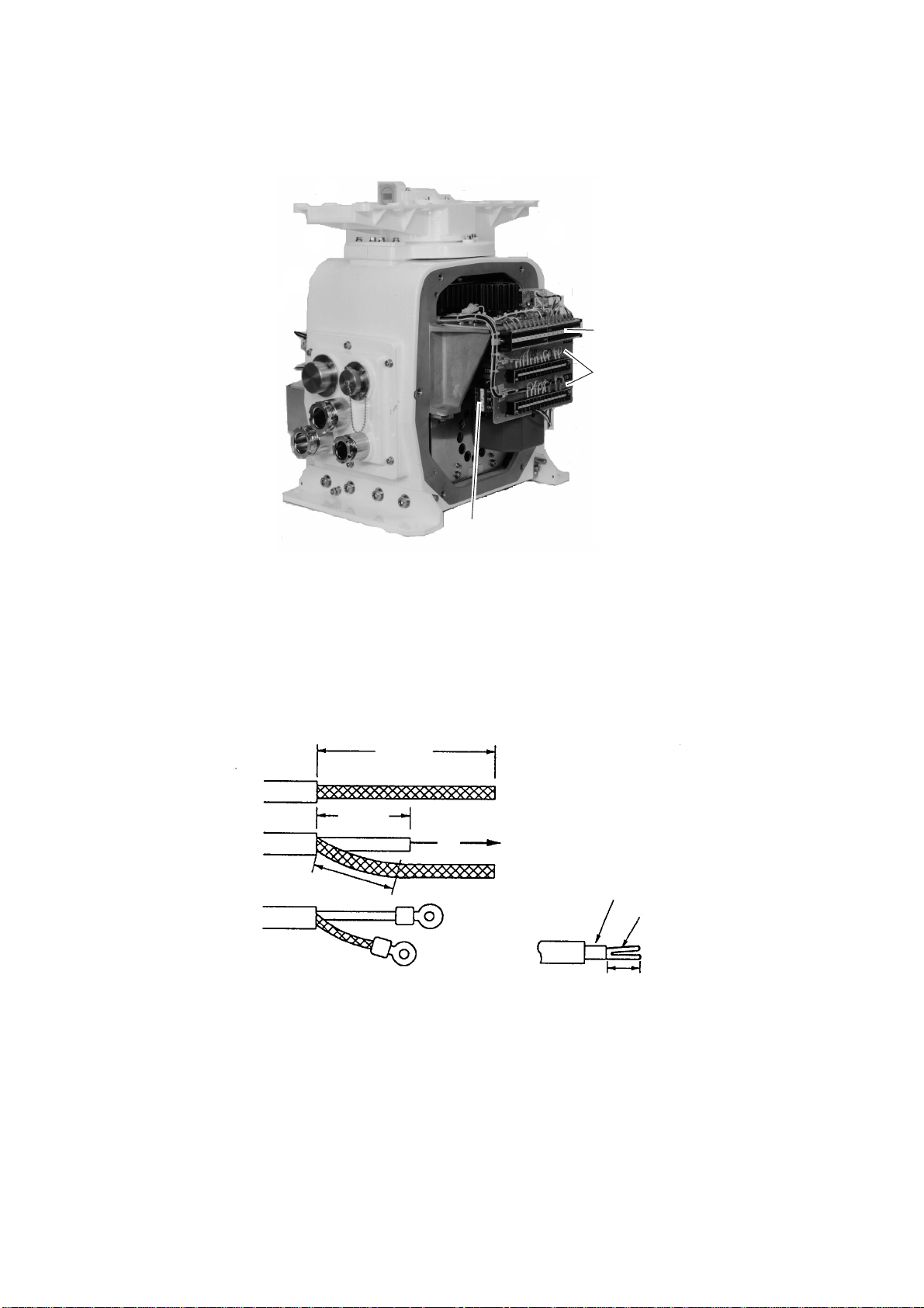
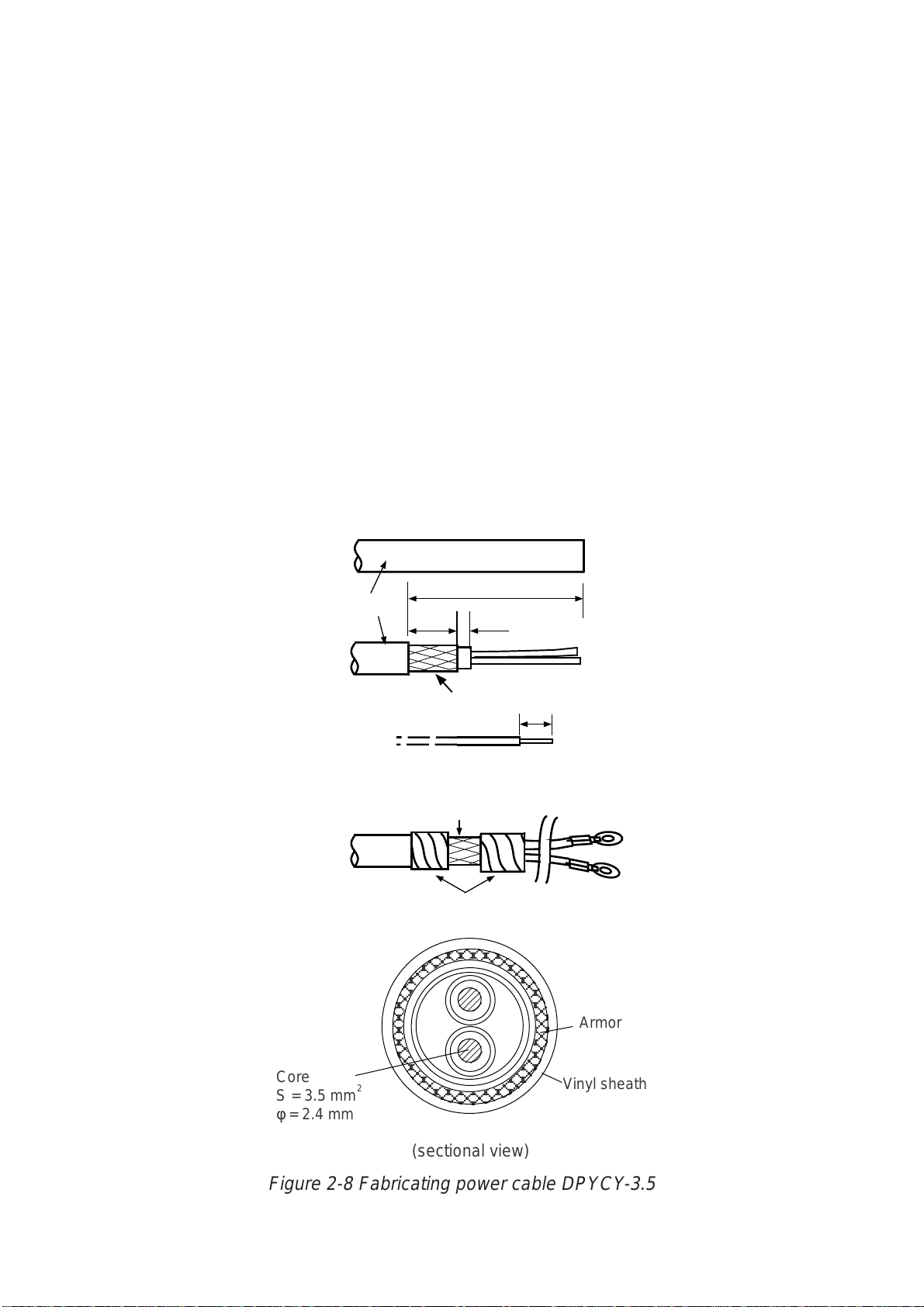
Fabricating the power cable DPYCY-3.5
DPYCY-3.5 is a Japan Industry Standard Cable; use equivalent.
1. Remove the vinyl sheath by 80 mm.
2. Cut off jute tape wrapped around the armor.
3. Unravel the armor to expose the cores by about 35 mm.
4. Remove insulation of cores by about 10 mm. Fix crimp-on lugs to the cores
and armor .
5. Cover the armor with vinyl tape, leaving the portion which will lie inside the
cable clamp untaped.
(a)
Vinyl sheath
(b)
(c)
(d)
DPYCY-3.5
Approx. 80 mm
40 mm
Clamp here.
5 mm
Armor
Taping
10 mm
Armor
Core
S = 3.5 mm
φ = 2.4 mm
2
(sectional view)
Vinyl sheath
Figure 2-8 Fabricating power cable DPYCY-3.5
2-5

Leading in cables to the display unit
The cable clamp may be positioned within the display unit (default arrangement),
outside the display unit. When the cable clamp is located outside the display unit,
use the bottom clamp front plate and bottom clamp rear plate (supplied with
installation materials).
Also, use the shielding foam (supplied) to protect the noise radiation.
Cable fed from back of display unit (default)
Panhead screw
M4X8
(D) Rear clamp
plate
(B) Power clamp
Nav equipment
(Gyrocompass)
Keyboard
Log
PWR
SCAN
Cable position in clamp
(Display unit, rear view)
Slave display
Navigation
External CRT
Hex bolt
M5X12 SUS
2 pcs
Hex bolt
M5X35 SUS
2 pcs
Hex bolt
M5X35 SUS
2 pcs
(C) Signal clamp
(Aluminum)
(Aluminum)
(Construction of
cable clamp)
(D) Rear clamp plate
Make sure shielding foam contacts rear chassis.
(C) Signal cable
Rear cable entrance
(Aluminum)
(B) Power clamp
(Aluminum)
Cable
(A) Rear clamp base
(Display unit, right-hand side view)
Shielding foam
(Display unit, rear view)
Figure 2-9 Default cable clamp position
• Place shielding foam between cables, and then attach foam to aluminum
clamps.
• Fill unused clamp holes with shielding foam.
(A) Rear clamp
base
2-6

Cable fed from outside display unit
Shielding foam
(A) Rear clamp base
M5x10 (2 pcs)
(Installation materials)
Rear cable entrance
(D) Rear clamp plate
(C) Signal clamp
(Aluminum)
(B) Power clamp
(Aluminum)
Bottom clamp front plate
(Installation materials)
(Display unit, right-hand side view)
Figure 2-10 Clamp position outside display unit
• Place shielding foam between cables inside of display unit, and then attach
foam to chassis.
• Fill unused clamp holes with shielding foam.
Cables fed from bottom of display unit
Lead in cables through the cable clamp at the rear of the console and ground
their shields in the cable clamp. For signal cable, remove vinyl sheath where
cable lies in cable clamp. Fasten cables with cable ties.
Seventh hole
from the top
Power Cable
(For display unit)
Close shutter door and cover
Close shutter and cover
with aluminum tape to
it with aluminum tape to keep
keep foreign objects out
foreign objects out of the
of the display unit.
display unit.
Performance
Monitor
Cable Arrangement in the Console (Top view)
SIGNAL CABLE:
Remove the vinyl sheath here.
(1300 mm from display unit end
of cable remove sheath by 70 mm.)
Gyrocompass
Power Cable
(For PM)
Log
NAV
Signal Cable
ARPA
Slave Display
Figure 2-11 Clamp position at bottom of display unit
2-7

Connections
Open the display unit and fix it with the stay. (For procedure see page 1-6.)
Remove the shield cover from the INT Board. Connect signal, power, gyro and
log cables as shown on the next page. Optional equipment are connected to the
INT Board. Be sure to ground the display unit.
From power
supply unit
Gyro
J442
Ground with this screw
(Console type only)
PTU Board
03P9245
MOTHER Board
03P9251
J448
INT Board
03P9252
J457
J450
Plug in coax.
cable here.
DJ1
J5
J4
J445
Scanner
GYRO CONVERTER
Log
Board 64P1106
Fasten with M3x8 screw
(2 pcs., supplied).
Ground terminal
for console mount
display unit
TB1
Ground terminal
for pedestal mount
display unit
POWER Switch
(Normally ON)
Connect referring to
interconnection diagram.
Loosen screws on terminal and slide terminal
forward.
M4X8 (2 pcs.)
2
1
1
2
3
4
5
6
7
8
J443
J444
J463
J458
J453
J451
J452
INT Board
J454
J455
J466
J462
J448
J469
J446
J467
J449
Connector Location
Bind cables so as not to pinch them
between the monitor and mounting base.
Pay special care tothe high voltage
J456
J465
line.
Figure 2-12 Display unit, inside view
2-8
CAUTION
Ground the equipment to
prevent electrical shock
and mutual interference.

Connectors on the INT Board
Table 2-1 Connectors on the INT Board
emanlangiSnoemaN
bcp
langiStupnI
langisoryG4Jnip3,HVbcpnO:*
goldeepS
langis
youbradaR
langis
etomeR
lanretxE
APRA
langis
langis
C232-SRC232-SR654Jnip4,HN
golanAGOLANA354Jnip3,HN
lanretxE
rezzub
GOL844Jnip3,HN .cte,mn/seslup002
RADAR
YOUB
RADAR-TXE
langisyalpsid
langiStuptuO
yalpsidevalS
langisrezzuBZUB-TXE154Jnip9,HNpma/wrekaepSlangisrekaepS
langisrotinoM944Jnip01,HN,suonorhcnysREV
7-JRro
APRA-TXE444Jnip8,HN,gniraeb,gnidaeH
EVALS244J
MRALATXE
)CA(
.on
5Jnip5,HV
rotcennoC
544Jnip4,HN
854Jnip8,HN
344J
254Jnip3,HN
rotcennoC
epyt
nip8,HN,141-DC,041-DC
.tinu
elbacilppA
tnempiuqe
,005-DG
,2KM005-DG
,008-DMF
08-DMF11*0
roftinuyalpsiD:1*
seires5012-RF
desuebnacradar
yalpsidevalssa
)tam
skrameR
)noitpo(6011P46A
reggirtxT
,gniraeb,gnidaeH
reggirtxT,oediv
,suonorhcnysROH
-rofCSTN(oediv
langiStuptuO/tupnI
atadSNIATAD.SNI554Jnip5,HN
7-JR7-JR754Jnip51,HN
8-JR8-JR614Jnip4,HNdraoBrehtoMnO
1529P30
atadvaNATADVAN054Jnip5,HN
atadAPRAATADAPRA454Jnip5,HN
FFO_NO_MPTNIP_MP114Jnip3,HXdraoBrehtoMnO
1529P30
Note: How to attach NH connector is shown on the next page.
2-9

How to attach NH connector
J
HOW TO ATTACH NH CONNECTOR TO SIGNAL CABLE
NH connector wire
NH connector
housing
1
Insert NH connector
wire into NH connector
housing.
Shrink tubing
20mm
2
Cut shrink tubing
in 20 mm lengths and
slip onto each wire.
Solder
3 Solder connector
to signal cable.
Heat shrink
4
tubing with soldering iron.
Figure 2-13 How to attach NH connector
2.3 Changing AC Power Specification of Display Unit
For 100 VAC or 220 VAC power, add or delete jumper wires on the PTU Board
and change the power fuses inside the display unit as shown in the table below
according to ship’s mains. The figure on below shows the location of the power
fuses and the jumper wires on the PTU Board.
Table 2-2 Jumper wire setting on the PTU board, fuse rating and power specification
BCP.cepSrewoP
annetnA
mpr
1PJ2PJ3PJ4PJ19PJ29PJ
A5429P30CAV511/011/001mpr42SEYSEYSEYONONONA01
D5429P30CAV032/022mpr42ONONONSEYONONA5
umper wire to use:
JP1: 0.8 dia. gilded wire
JP2, JP3, JP4, JP91, JP92: type ERD-S2TCOV
JP1
Fuse
JP2
JP3
JP4
03P9245
JP92
JP91
PTU Board
Figure 2-14 Display unit, inside view
rewoP
sesuF
2-10

2.4 Power Supply Units
Power supply unit PSU-004
TB
PTB14
TB
PTB11
Thermal relay
K2
Relay K3
Relay K1
Photo No. 3148
TB
PTB13
TB
PTB12
Figure 2-15 Power supply unit PSU-004
The table below lists the type of thermal relay used in the PSU-004. The type of
the relay and its presetting differs according to ship’s mains.
Table 2-3 Thermal relay in power control unit PSU-004
s'pihS
sniaM
CDV421500-BSRD505101CABA5
tinUrennacS
epyTgnitaR
)2K(yaleRlamrehT
Fabricate the power supply cable as shown on page 2-5.
2-11

Power supply unit PSU-001
Two cables run to the Power Supply Unit PSU-001, the power cable (DPYCY-
3.5) and the signal cable (660V-MPYCY-16). The figure below shows the location of the terminal boards inside the PSU-001. Wire the unit as shown in the
interconnection diagram.
5
Vinyl sheath
ANTI-CORROSIVE
SHEATH
Armor
150 mm
10 5
Vinyl sheath
Vinyl tape
Clamp here.
Power Cable DPYC-3.5 Signal Cable 660V-MPYCY-16
Crimp-on lug
FV5.5-4
Armor
.oNeroCotdetcennoCguLno-pmirC
9ot12BTP)deR(3M-52.1VF
61ot011BTP)eulB(4-2VF
Vinyl tape
Clamp here.
Figure 2-16 Fabrication of power cable and signal cable
PTB2
PTB1
Cable clamp
Figure 2-17 Power supply unit PSU-001
2-12

INITIALIZATION AND ADJUSTMENT
3.1 Tuning Initialization
Tune the radar as follows: Press [RADAR MENU] [0] [0] [2] [0] [0] [0] [0] (TUNE
INITIALIZE on RADAR 3 menu) and press the [ENT] key.
3
.2 Accessing Menus for Initialization and Adjustment
To access them do the following:
1. Turn on the power.
2. Press the [RADAR MENU] key five times while pressing and holding down
the [HL OFF] key.
Restoring default settings
1. Press [RADAR MENU] [0] [0] [0] [2] [0] [0] [0] to display the INITIAL SETTING
4 menu.
2. Press the [0] key to select FACTORY DEFAULT.
3. Press the [ENTER] key five times, and turn the power off and on again.
4. “Initializing” appears during restoring. It takes about 90 seconds to restore the
default settings, after which the normal display appears. Confirm that
“2.MODEL” is set to “OTHER X-BND” on the INITIAL SETTING 4 menu.
3.3 Adjusting Video Signal Level
When the signal cable is very long, the video amplifier input level decreases,
shrinking target echoes. To prevent this, confirm (and adjust if necessary) video
amplifier input level.
1. Connect an oscilloscope to TP6 on the INT Board (03P9252) in the display
unit.
2. Transmit on the 12 nm range.
3. Adjust R21 on the INT Board so the value of TP6 is 4 Vpp. (For remote display, adjust R134 on the INT Board.)
TP1
R134
INT Board
(03P9252)
3-1
TP6
R21
Figure 3-1 Display pedestal

3.4 Heading Alignment
You have mounted the scanner unit facing straight ahead in the direction of the
bow. Therefore, a small but conspicuous target dead ahead visually should appear on the heading line (zero degrees).
In practice, you will probably observe some small bearing error on the display
because of the difficulty in achieving accurate initial positioning of the scanner
unit. The following adjustment will compensate for this error.
Correct bearing
relative to heading
Target
a
270
Scanner mounted
error to port
(HDG SW advanced)
000
010
350
020
340
330
320
310
300
290
280
260
250
240
230
220
210
200
030
040
140
150
160
190
170
180
Picture appears
deviated clockwise.
a
050
060
070
080
090
100
110
120
130
Apparent
position
of target
Scanner mounted
error to starboard
(HDG SW delayed)
Apparent position
of target
Target
b
b
000
010
350
020
340
330
320
310
300
290
280
270
260
250
240
230
220
210
200
030
040
050
060
070
080
090
Correct
100
110
bearing
120
130
relative to
140
150
160
190
170
180
heading
Picture appears
deviated counterclockwise.
Figure 3-2 Heading alignment
1. Turn on the power. Press [RADAR MENU] [0] [0] [0] [2] [2] to select HL ALIGN
on the INITIAL SETTING1 menu.
2. Select a target echo (by gyrocompass, for example) at a range between 0.125
and 0.25 nm, preferably near the heading line.
3. Operate the EBL control to bisect the target echo with the heading line. (The
value shown on the display is scanner position in relation to ship's bow.)
4. Press [ENTER] to finish.
3-2

3.5 Adjusting Sweep Timing
Sweep timing differs with respect to the length of the signal cable between the
scanner unit and the display unit. Adjust sweep timing at installation to prevent
the following symptoms:
• The echo of a "straight" target (for example, pier), on the 0.25 nm range, will
appear on the display as being pulled inward or pushed outward. See Figure
3-3.
• The range of target echoes will also be incorrectly shown.
(1) Correct
Figure 3-3 Examples of correct and incorrect sweep timings
1. Turn on the power. Press [RADAR MENU] [0] [0] [0] [2] [3] to select TIMING
ADJ on the INITIAL SETTING1 menu.
2. Transmit on the 0.25 nm range.
3. Adjust radar picture controls to display picture properly.
4. Select a target echo which should be displayed straightly.
5. Adjust the VRM control to straighten the target echo.
6. Press [ENTER].
(2) Target pushed
inward
3.6 Suppressing Main Bang
If main bang appears at the screen center, suppress it as follows.
1. Turn on the power. Transmit on a long range and then wait ten minutes.
(3) Target pushed
outward
2. Adjust [GAIN] control to show a slight amount of noise on the display.
3. Select the 0.25 nm range. Adjust the [A/C SEA] control to suppress sea clutter.
4. Press [RADAR MENU] [0] [0] [0] [2] to open the INITIAL SETTING1 menu.
5. Press [7] to select 7. MBS.
6. Adjust the VRM control to adjust timing; the EBL control to adjust level.
7. Press [ENTER].
3-3

3.7 Confirming Magnetron Heater Voltage
Magnetron heater voltage is adjusted at the factory using a 15 m signal cable.
Therefore, when the length of the cable is other than 15 m, confirm that magnetron heater voltage is within the prescribed rating as follows:
1. Turn on the radar and press [RADAR MENU] [0] [0] [0] [2] [0] to open the
INITIAL SETTING2 menu.
2. Press [5] to select the 5. SCANNER STOPPED field and the TX option.
3. Turn off the antenna switch in the display unit.
ANTENNA
switch
ON
OFF
ANTENNA
TUNE
DEGAUSS
PM
ERROR
Figure 3-5 Antenna switch in tuning compartment
4. Turn off screen brilliance.
5. Transmit on the 0.125 nm range.
6. Connect a multimeter, set to the 10 VDC range, between #1(+) and #2(-) of
J829 in the scanner unit.
7. Adjust the position of the sliding contact R812 to show a value between 7.0 V
and 7.5 V on the multimeter.
8. Remove the TX-HV fuse (F801, 0.5A) from the power supply unit for the scanner unit.
9. Transmit on maximum range.
10.Adjust the position of the sliding contact R811 to show a value between 4.5 V
and 5.0 V on the multimeter.
1 1.Insert TX-HV fuse F801.
12.Press [RADAR MENU] [0] [0] [0] [2] [0] [5] to select the 5. SCANNER STOPPED
field and the TX option.
3-4

R813
Fuse
801
Photo No. 2914
Figure 3-6 Scanner unit, power supply unit PSU-001
Note: When the length of the cable between the scanner unit and the power
supply unit is more than 60 meters, the magnetron heater voltage may not reach
the lower limit due to voltage drop. If this is the case, increase the voltage with the
sliding contact R813 in the power supply unit, and readjust with R811, R812 in
the scanner unit.
3-5

3.8 Initial Setting Menus
The INITIAL SETTING menus (four menus) and the OWN SHIP INFORMA TION
menu setup the radar according to expected usage, authorities specification, ship's
characteristics, operator's preference, etc. Set items on each menu in accordance with regulations/operator's preference. After entering initial settings, reset
the power.
Press [RADAR MENU] [0] [0] [0] [2]
[OWN SHIP INFORMATION]
1 [INITIAL SETTING(1)]
2 SHIP’S LENGTH 000m
3 SHIP’S WIDTH 00m
4 RADAR POSN FOR BOW 000m
FOR PORT 00m
5 NAV ANT POSN FOR BOW 000m
FOR PORT 00m
6 TURN RATE 00KT
00.0° / s
00KT
00.0° / s
7 SPEED RATE 00KT
0.00KT/s
00KT
0.00KT/s
Press [0]
[INITIAL SETTING 4]
1 [INITIAL SETTING(3)]
2 MODEL FR-2115, 2125/
OTHER X-BND/
FR-2165DS, 2135SW/
OTHER S-BND
3 TYPE R/N/G/D
4 CTR STC CURVE L/M/H
5 RJ-7 OFF/ON
6 RJ-8 OFF/ON
ANT A
FR-2115, 2125/
OTHER X-BND/
FR-2165DS, 2135SW/
OTHER S-BND
ANT B
FR-2115, 2125/
OTHER X-BND/
FR-2165DS, 2135SW/
OTHER S-BND
7 SHIP’S TYPE DEEP SEA/FISHING/
LONG LINE FISHING
8
9 CABLE LENGTH 500m/5000m
0 FACTORY DEFAULT
Press [6]
[INITIAL SETTING 1]
1 [FUNCTIONS(4)]
2 HL ALIGN
EBL 0.0°
3 TIMING ADJ
VRM 00.00
4 ANT HGT 5m/7m/10m/15m/
20m/30mMORE
5 LOG PULSE 200P
6 [OWN SHIP INFORMATION]
7 MBS MBS TIMING VRM 0
MBS LEVEL EBL 0
8 ON TIME 000000.0H
9 TX TIME 000000.0H
0 [INITIAL SETTING(2)]
Press [0]
[INITIAL SETTING 2]
1 [INITIAL SETTING(1)]
2 LOG GYRO INPUT LOG
PULSE/SERIAL DATA
GYRO
AD/10/SERIAL DATA
3 OWN SHIP VECTOR COMPASS/COURSE
4 KEY BEEP ON/OFF
5 SCANNER STOPPED ST-BY/TX
6 VIDEO SIG ANALOG/DIGITAL
7 ALARM LEVEL 4/5/6/7
8 DISPLAY MAIN/SUB
9 SECTOR BLKG OFF/ON
000° → 000°
000° → 000°
0 [INITIAL SETTING(3)]
Press [0]
[INITIAL SETTING 3]
1 [INITIAL SETTING(2)]
2 TRAILS RESTAR T OFF/ON
3 ECHO AVG W/O GYRO OFF/ON
4 HEAD UP TB SCALE DEG/16POINT
5 CTR ECHO STRETCH OFF/ON
6 VIDEO CONTRAST 1/2/3
7 MAXIMUM RANGE 72/96/120
8 ECHO FULL COLOR OFF/ON
9 INDEX LINES 2/3/6
0 [INITIAL SETTING(4)]
3-6

INITIAL SETTING1 menu
Keying sequence: [RADAR MENU] [0] [0] [0] [2]
HL ALIGN: Aligns heading.
TIMING ADJ: Adjusts sweep timing.
ANT HGT: Enter height of scanner above water. Select from 5 m, 7 m, 10 m, 15
m, 20 m, or more than 30 m.
LOG PULSE: Enter speed log's pulse rate.
OWN SHIP INFORMATION: Enter ship's characteristics; length, width, radar
scanner position, navigation antenna position, turn rate, and speed rate. See the
description on the next page for further details.
MBS: Suppresses main bang.
ON TIME, TX TIME: Shows number of hours the radar has been turned on and
transmitted, respectively. Value can be changed.
INITIAL SETTING2 menu
Keying sequence: [RADAR MENU] [0] [0] [0] [2] [0]
LOG GYRO INPUT: Select LOG or GYRO input type. LOG: Select pulse or serial
data. GYRO: Digital from A/D converter or serial data.
OWN SHIP VECTOR: Select reference for own ship vector; compass or course.
KEY BEEP: Turns key response beep on or off.
SCANNER STOPPED: Set to ST-BY in normal use. TX enables transmission
state without scanner rotation.
VIDEO SIG: Set to ANLG (analog) for normal use. Select DIGITAL to adjust QV
(Quantized Video).
ALARM LEVEL: Sets echo strength which triggers guard alarm. "7" is strongest
echo; "4" is medium strength echo.
DISPLAY: Select radar display function; main or sub (slave).
SECTOR BLKG: Sets area (up to 2) where no radar pulses will be transmitted.
For example, set the area where an interfering object at the rear of the scanner
would produce a dead sector (area where no echoes appear) on the display. To
enter an area, select ON and enter relative bearing range of the area.
INITIAL SETTING3 menu
Keying sequence: [RADAR MENU] [0] [0] [0] [2] [0] [0]
TRAILS RESTART: Selects whether to restart or discontinue target trails when
changing the range. ON restarts trailing on newly selected range; OFF discontinues trails.
ECHO AVG W/O GYRO: Echo averaging can be turned on without gyrocompass
connection.
3-7

HEAD UP TB SCALE: Bearing scale may be shown in degrees or compass
points in the head-up mode.
CTR ECHO STRETCH: Turn on to enlarge echoes in the range up to the first
range ring.
VIDEO CONTRAST: For factory use. Do not change setting.
MAXIMUM RANGE: For factory use. Do not change setting.
ECHO FULL COLOR: Echoes may be displayed in one color or multi-color. Se-
lect ON for multi-color display.
INDEX LINES: Selects the number of index lines to display; 2, 3, or 6.
INITIAL SETTING4 menu
Keying sequence: [RADAR MENU] [0] [0] [0] [2] [0] [0] [0]
MODEL: Selects radar model.
TYPE: Selects specification of radar. Select R for R type; G for IMO type.
CTR STC CURVE: Selects level of STC affect; Low, Medium or High.
RJ-7, RJ-8: Selects which Interswitch unit to use.
SHIP'S TYPE: Select class of vessel; deep sea, fishing, long line fishing.
CABLE LENGTH: Set for "500."
FACTORY DEFAULT: Restores all menus' default settings.
OWN SHIP INFORMATION menu
Keying sequence: [RADAR MENU] [0] [0] [0] [2] [6]
SHIP'S LENGTH: Enter ship's length.
SHIP'S WIDTH: Enter ship's width.
RADAR POSN: Enter distance from both bow and port to the radar scanner
location.
NAV ANT POSN: Enter distance from both bow and port to the navigation an-
tenna location.
TURN RATE: Enter ship's turn rate.
SPEED RATE: Enter ship's speed rate.
3-8

INSTALLATION OF OPTIONAL EQUIPMENT
4.1 Gyro Converter GC-8
The Gyro Converter GC-8, incorporated inside the radar display unit, converts
analog gyrocompass reading into digital coded bearing data for display on the
radar display.
This section explains how to install and setup the GC-8 (mainly consisting of the
GYRO CONVERTER Board) and set it up according to gyrocompass connected.
Installation and connection of the GYRO
CONVERTER Board
Necessary Parts: GC-8-2 (008-446-520)
emaNepyTytQ.oNedoC
draoBretrevnoCoryG6011P461022-214-400
swercSW0072C,8x3M5404-188-000
rekcitS11202-410-461107-231-001
1) Turn off the power.
2) Open the display unit. See Chapter 1 for instructions.
3) Fasten the GYRO CONVERTER Board inside the display unit with four
washerhead screws (supplied).
PTU BOARD
03P9245A F
MB BOARD
03P9251
GYRO CONVERTER
BOARD 64P1106
INT BOARD
03P9252
Figure 4-1 Display unit, inside view
4-1

4) Connect the GYRO CONVERTER Board to the INT Board (cables supplied
with GC-8) as shown below.
INT Board GYRO CONVERTER Board
J446 (4P) J7 (5P)
J465 (6P) J1 (14P)
J5
To gyro
J4
J446
INT BOARD
03P9252
J7
J1
Fix cable to chassis
with cable tie.
GYRO CONVERTER
BOARD 64P1106
Figure 4-2 Display unit, inside view
5) Confirm gyrocompass specifications and set up the DIP switches and jumper
wires on the GYRO CONVERTER Board according to gyrocompass connected:
• Setting jumper wires and DIP switches by gyrocompass
specifications: page 4-3
• Setting jumper wires and DIP switches by make and
model of gyrocompass: page 4-5
• Location of jumper wires and DIP switches: page 4-6
6) Solder the gyrocompass cable to the VH connector assemblies (supplied).
7) Attach instruction label (supplied) to the shield cover for the INT and GYRO
CONVERTER boards.
8) Close the display unit.
9) Turn the power off and on to reset the CPU.
4-2

Connection of external power supply
An external power supply is necessary when the repeater signal is step-by-step
type and the step voltage is below 20V or output voltage is less than 5 W.
1. Cut jumper wire JP1 on the GYRO CONVERTER Board when an external power
supply is used.
2. Connect gyro cable and power cable as shown below.
GYRO CONVERTER Board
(A) 64P1106
External Power Supply
20 - 135 VAC
20 - 100 VDC
Gyrocompass
(Step type)
S1
S2
S3
COM
F.G.
J5
1 > R2
2 > R1/COM
Either connection
in case of DC
polarity.
J4
1 > S1
2 > S2
3 > S3
4 > T
5 > F.G.
Figure 4-3 Connection of external power supply to GYRO CONVERTER Board
DIP switch, jumper wire settings
Default setting
The default setting of all DIP switches is off and all jumpers wire are set to “#1.”
(Note that jumper wire JP1 is set at #1, #2, and #3.) In those settings the gyrocompass having the following characteristics can be directly connected; modification
of the GYRO CONVERTER Board is not necessary.
AC synchronous signal: 50/60 Hz
Rotor voltage: 60 V to 135 V AC
Stator voltage: 60 V to 135 V AC
Gear ratio: 360x
Supply voltage: 30 V to 135 V AC
If the specifications of the gyrocompass differ from those mentioned above, change
jumper wire and DIP switches settings on the GYRO CONVERTER Board. Settings may be changed according to gyrocompass specifications or make and model
of gyrocompass (see page 4-5). For the location of DIP switches and jumper wires,
see page 4-6.
4-3

Setting method 1: by gyrocompass specifications
1) Gyrocompass type 2) Frequency
Gyrocompass
type
AC synchronous OFF OFF OFF #1,
DC synchronous OFF OFF OFF #2,
DC step ON OFF OFF #4,
Full-wave
pulsating current
Half-wave
pulsating current
3) Rotor voltage
(between R1 & R2)
Rotor voltage SW 2-1 JP3 Stator voltage SW 2-2 SW 2-3 JP2
20V to 45V AC ON #2 20V to 45V AC, or
30V to 70V AC OFF #2
40V to 90V AC ON #1 20V to 45V AC, or
60V to 135V AC OFF #1
SW
1-4SW1-5SW1-6
OFF ON OFF #4,
ON ON OFF #4,
JP1 Frequency SW
#2, #3
#3, #4
#5, #6
#5, #6
#5, #6
4) Stator voltage
(between S1 and S2)
20V to 60V DC
20V to 60V DC
40V to 90V AC ON OFF #1
60V to 135V AC OFF OFF #1
1-7SW1-8
50/60Hz OFF OFF AC synchronous
400Hz ON OFF AC synchronous
500Hz OFF ON AC synchronous
DC ON ON DC synchronous
ON OFF #2
OFF OFF #2
Remarks
pulsating current
pulsating current
pulsating current
DC step
5) Ratio 6) Supply voltage
Ratio SW1-1 SW 1-2 SW1-3 Supply voltage JP4 JP5
360x OFF OFF OFF 20V to 45V AC, or
180x ON OFF OFF
90X OFF ON OFF 30V to 135V AC, or
36X ON ON OFF
20V to 60V DC
40V to 100V DC
7) AD-10 format data
Tx interval
Select data transmitting interval for ports 1 to 6 by jumper wires
JP6 and JP7.
Note: The Tx interval is available in 25 msec or 200 msec. 25
msec is for radar; 200 msec is for all other equipment.
#2 #2
#1 #1
8) NMEA-0183
Tx interval
Tx
interval
2 seconds ON
1 second OFF
SW2-4
4-4

Setting method 2: by make and model of gyrocompass
rekaMsledoMnoitacificepSWS
ONURUF007-YGpetsCD
ztuhcsnA3,2dradnatSsuonorhcnysCA
6,4dradnatSsuonorhcnysCA
02dradnatSpetsCD
awagokoY
cetvaN
htialP(
)epyt
htialPIII/IITAGVANsuonorhcnysCA
cemikoT
yrrepS(
)epyt
ikasawaK18-XGsuonorhcnysCA
nworbamrA1-LKM,01-KM
nostreboR08-RKSpetsCD
3/2/A1/1-C
55-B,55-A
007-ZMCpetsCD
005/X003
003
3/2-SPI
05-ZMC
etoN
11/2/1-SE
002-GT
H/L732RP
12MG
41-KM
T/2/1-DOM
71-SE,041
302/
0006-GTpetsCD
11-MGsuonorhcnysCA
4-DOM
/X052-ZMC
/002/001-ZMC
3/1/Z1-D,rJ1-C
/201/101-TLG
701/K601/301
011/A11-SE
0002/R222RP
IE-KN,NE-KN
041/031-RSpetsCD
0005/001-GT
/031/753-RP
202/102-TLG
61-SE,021-RS
03/02/01-KM
,1531SEIRES
x081V001
zH06/05
x063
zH06/05
x063
x081V53
zH06/05
x063
x081V42
petsCD
x081V53
zH06/05
x063
pets
x081V53
zH06/05
x063
zH06/05
x63
zH06/05
x09
petsCD
x081V07
x081V07
petsCD
x081V07
x081V42
zH06/05
x09
petsCD
x081V53
zH06/05
x09
petsCD
x081V05
x081V53
rotcellocnepo,eriw-5
V06/05:egatlovrotoR
V22:egatlovrotatS
V06/05:egatlovrotoR
V09:egatlovrotatS
)+(eriw-3,)-(MOC
suonorhcnysCA
V06/05:egatlovrotoR
V22:egatlovrotatS
)-(eriw-3,)+(MOC
x063suonorhcnysCDFFOFFOFFOFFOFFOFFONONO-NOFFO-omeR
)-(eriw-3,)+(MOC
suonorhcnysCA
V001:egatlovrotoR
V09:egatlovrotatS
)-(eriw-3,)+(MOC
V06/05:egatlovrotoR
V86:egatlovrotatS
suonorhcnysCA
V011/001:egatlovrotoR
V09:egatlovrotatS
suonorhcnysCA
V011/001:egatlovrotoR
V22:egatlovrotatS
)+(eriw-3,)-(MOC
rotcellocnepo,eriw-5
)-(eriw-3,)+(MOC
V001:egatlovrotoR
V09:egatlovrotatS
V011/001:egatlovrotoR
V09:egatlovrotatS
)-(eriw-3,)+(MOC
)+(eriw-3,)-(MOC
WS
WS
WS
WS
WS
WS
WS
WS
WS
1-1
2-1
3-1
4-1
5-1
6-1
7-1
8-1
1-2
NOFFOFFONOFFOFFONONO- FFOFFO,4#
FFOFFOFFOFFOFFOFFOFFOFFOFFONOFFO,1#
FFOFFOFFOFFOFFOFFOFFOFFOFFOFFOFFO,1#
NOFFOFFONOFFOFFONONO-NOFFO,4#
FFOFFOFFOFFOFFOFFOFFOFFOFFONOFFO,1#
NOFFOFFONOFFOFFONONO-NOFFO-omeR
NOFFOFFONOFFOFFONONO-NOFFO,4#
FFOFFOFFOFFOFFOFFOFFOFFOFFOFFOFFO,1#
NOFFOFFONOFFOFFONONO– NOFFO-omeR
FFOFFOFFOFFOFFOFFOFFOFFOFFOFFOFFO,1#
NONOFFOFFOFFOFFOFFOFFOFFOFFOFFO,1#
FFONOFFOFFOFFOFFOFFOFFOFFOFFOFFO,1#
NOFFOFFONOFFOFFONONO– FFOFFO,4#
NOFFOFFOFFONOFFOFFOFFO– FFOFFO,4#
NOFFOFFONOFFOFFONONO– FFOFFO,4#
NOFFOFFONOFFOFFONONO-NOFFO,4#
FFONOFFOFFOFFOFFOFFOFFOFFOFFOFFO,1#
NOFFOFFONOFFOFFONONO– NOFFO,4#
FFONOFFOFFOFFOFFOFFOFFOFFOFFOFFO,1#
NOFFOFFONOFFOFFONONO– FFOFFO,4#
NOFFOFFONOFFOFFONONO– NOFFO,4#
WS
2-2
3-2
1PJ2PJ3PJ4PJ5PJ
2#-1#1#
6#,5#
2#2#1#1#
3#,2#
2#1#1#1#
3#,2#
2#– 2#2#
6#,5#
2#2#1#1#
3#,2#
2#–
ev
2#–
ev
2#– 2#2#
6#,5#
1#1#1#1#
3#,2#
2#–
ev
2#2#1#1#
3#,2#
1#1#1#1#
3#,2#
1#1#1#1#
3#,2#
2#– 1#1#
6#,5#
2#– 1#1#
6#,5#
2#– 1#1#
6#,5#
2#– 2#2#
6#,5#
1#1#1#1#
3#,2#
2#– 2#2#
6#,5#
1#1#1#1#
3#,2#
2#– 1#1#
6#,5#
2#– 2#2#
6#,5#
∗∗
∗∗
∗∗
*: Set JP4 and JP5 according to the voltage of the external power supply.
Note: If CMZ-50 has 35VDC, set JP1 to #4, #5, #6.
4-5

Location of DIP switches, jumper wires on the GYRO CONVERTER
Board
JP2
(Rotor voltage)
JP3
(Stator voltage)
JP5, JP4
(Supply voltage)
JP1
(Gyro type)
Fuse
(2A)
J5
(Rotor signal input,
external power input)
J4
(Stator signal input)
SW1
DIP switch
(IEC-61162-1 output port)
64P1106
J6
J7
(Data output port #1)
Figure 4-4 GYRO CONVERTER Board
Setting the heading readout on the radar display
J12
(Data output
port #6)
J11
(Data output
port #5)
J10
(Data output
port #4)
SW2
DIP switch
JP6, JP7
(AD formal
data Tx interval)
J9
(Data output port #3)
J8
(Data output port #2)
Confirm that the gyrocompass is giving a reliable readout. Then, set the heading
readout on the radar display with the gyrocompass readout as follows:
1. Press [RADAR MENU] to display the FUNCTIONS 1 menu.
2. Press the [0] key twice to display the FUNCTIONS 3 menu.
3. Press the [9] key to select the GYRO SETTING option.
4. Rotate the EBL control to align the radar’s HDG readout with the gyrocompass.
5. Press [ENTER] to conclude the setting.
4-6

4.2 ARP Board ARP-26
The ARP Board ARP-26, which provides ARPA functions, is an optional circuit
board which is accommodated in the display unit of the FR-2105 series radar.
Necessary Parts: ARP-26-2E (008-485-500)
emaNepyTytQ.onedoC
draobPRAB2009P811056-374-800
Installation of the ARP board
1. Remove the bottom cover of the display unit by unfastening four screws.
2. Set the ARP Board in the center slot of the PCB card case.
PCB card case
Top: RP Board (Option)
Middle: ARP Board (Option)
Bottom: SPU Board
Figure 4-5 Display pedestal inside view
3. Adjust the ARP referring to the procedure on the next page.
4-7

ARP board adjustment
1. Turn the GAIN, A/C SEA and A/C RAIN controls fully counterclockwise, and
then transmit on the 12 nm range.
2. Connect a digital multimeter between TP7(+) and TP6(-) on the ARP Board.
TP7
TP6
R104
R103
Figure 4-6 ARP Board (18P9002B)
3. Adjust R104 on the ARP Board so the multimeter reads between 0.09 and 0.14
VDC.
4. Set controls and switches as below.
GAIN: fully clockwise (max.)
Interference rejector: OFF
Range: 24 nm
Echo stretch: OFF
5. Press [RADAR MENU] [0] [0] [0] [0] open the INITIAL SETTING3 menu.
6. Set the VIDEO SIG field to DIGITAL and press [ENTER].
7. Adjust R103 on the ARP Board so noise just appears on the display.
Too little noise
Proper noise
Too much noise
Figure 4-7 How to adjust noise
8. Set VIDEO SIG to ANALOG and press [ENTER].
4-8

Final check
Connect a gyrocompass and a log to the radar and place the radar under transmit
state. Confirm that LEDs CR9, CR10, CR11, CR12, CR15 and CR16 on the ARP
Board are off. If ship's speed is zero, or other signal is not being input, corresponding LED will light.
CR16 LOG
CR15 GYRO
CR12 TRG
CR11 VID
CR10 BRG
CR9 HDG
S1
4#3#2#1#
FFOFFOFFOFFO
Figure 4-8 ARP Board ARP-26
4-9

4.3 RP Board RP-26
The RP Board RP-26, which providesvideo plotter functions, consists of a circuit
board and a card drive both of which are accommodated in the display unit of the
FR-2105 series radar.
Table top/console type
Necessary Parts: RP-26-T-2E (008-485-520)
draobPR8920P411046-784-800
emaNepyTytQ.onedoC
.yssaesacdraC–1–
BwercsdaehnaPW0072C8x4M4544-188-000
BwercsdaehnaPW0072C8x3M2404-188-000
AwercsdaehnaPW0072C5x6.2M2379-008-000
rehsawkcoldehteeT
)hteetedistuO(
.yssaelbaC25-A-A-D001-6FIH1355-731-000
W1915C4M1605-468-000
1. Lift the monitor and fix it with the stay. Refer to Chapter 1 for instructions.
2. Remove the right arm cover from the control head.
3. Fasten the card case to the right arm cover as follows:
a) Fasten the ground wire with an M4x10 screw and washer (supplied) as shown
below .
b) Fasten the arm cover to the card case with three M4x8 screws (supplied).
Panhead screw
M4X10
Arm cover (right)
Panhead screw
M4X8 3 pcs.
Ground wire
Washer
M4
Card case
Figure 4-9 Fastening the card case to the right arm cover
4-10

4. Unfasten the front panel from the display pedestal.
5. Pass the connector from the card case through the hole in the display pedestal.
Display pedestal
Front panel
Figure 4-10 Display pedestal
6. Set the RP Board (14P0298) in the top slot of the pcb card case. See page 4-7
for the location of the pcb card case.
7. Run the connector from the card case in front of the GYRO CONVERTER
Board.
8. Plug the connector in J1 on the RP Board.
9. Fasten the ground wire from the connector at the location shown below.
RP connector
INT Board
Fasten ground wire from connector to this screw.
RP Board
GYRO
CONVERTER
Board
FRONT
(TOP VIEW)
ARP Board
SPU Board
J1
Route cable between ARP and SPU Boards.
(FRONT VIEW)
Figure 4-11 Display pedestal, top view
4-11

10.Fasten the front panel on the display pedestal.
11.Retract the stay to close the display unit.
12.Fasten the right arm cover.
Separate type control head
Necessary parts: RP-26-Z-2E (Code no. 008-491-400)
emaNepyTytQ.oNedoC
.yssAesaCdraC–1–
draoBPR8920P411046-784-800
BwercSdaeHnaPW0072C8x4M1544-188-000
BwercSdaeHnaPW0072C8x3M2404-188-000
AwercSdaeHnaPW0072C5x6.2M2379-008-000
1. Lift the monitor. See Chapter 1 for instructions.
2. Fasten the mounting base with one M4 x 8 screw as below.
Fasten with
M4 x 8 screws.
Fasten with M3 x 8
screws (2 pcs.)
Figure 4-12 Display unit, inside view
3. Fix the mounting base to front panel with two M3 x 8 screws.
4. Set the M-card case lid to the hole in the front panel and fix with two M2.6 x 5
screws.
4-12

Control section
M-card base
Control section
front panel
Pan Head
Screw
M2.6X5
(2 pcs.)
M-card
case lid
Figure 4-13 Display pedestal, front view
5. Loosen six screws to remove the front panel on the display pedestal.
6. Set the RP Board (14P0298) in the top slot of the pcb card case.
7. Run the connector from the card case in front of the GYRO CONVERTER
Board.
8. Plug the connector in J1 on the RP Board.
9. Fasten the ground wire from the connector at the location shown below.
RP connector
INT Board
Fasten ground wire from connector to this screw.
RP Board
ARP Board
SPU Board
GYRO
CONVERTER
Board
FRONT
(TOP VIEW)
J1
Route cable between ARP and SPU Boards.
(FRONT VIEW)
Figure 4-14 Display pedestal, top view
4-13

10.Fasten the front panel of the display pedestal.
11.Fasten the ground wire to the location shown in Figure 4-14.
12.Close the monitor.
4.4 Performance Monitor PM-30
Necessary parts: PM-30 and OP03-150 (Code no. 008-485-490)
emaNepyTytQ.oNedoC
draoBMP5229P301026-784-800
wercSdaeHnaPW0072C8x3M3404-188-000
.yssArotcennoCAA-003L-P3HV2410-141-000
1. Lift the monitor. See Chapter 1 for instructions.
2. Fasten the PM Board 03P9225 to the location shown below with three screws
(M3 x 8).
PM Board
03P9225
J411
J401
Figure 4-15 Display unit, inside view
3. Connect the connector P401 coming from J411 to J401 on the PM Board.
4. Connect two connector assemblies (VH3P-L300-AA) to J402 and J403.
5. Solder the other end of there connector assemblies with external cables, one
from ship’s mains and one from the PM-30.
6. Close the monitor.
4-14

4.5 Alarm Kit
Necessary parts: OP03-156 (Code no. 008-500-650)
The alarm kit mainly consists of a circuit board and connection cables, and provides alarm output to ship’s bridge alarm system.
Contents of Alarm Kit OP03-156
emaNepyT.oNedoCytQ
draoBMRALA2629P30086-005-8001
.yssArotcennoCHN)P9-9(0991-30007-005-8001
.yssArotcennoCHN)P3(1991-30017-005-8004
dnaBelbaCN3-PH100-075-0001
eiTelbaC001-VC223-075-0003
BwercSdaeh-naPW0072C8X3M404-188-0004
BwercSdaeh-naPW0072C21X4M744-188-0001
Procedure
Refer to the figure below for parts locations.
1. Raise the monitor and fix it with the stay. (See page 1-5 for instructions.)
2. Unfasten four screws to dismount the shield cover for the INT Board.
3. Fasten the ALARM Board to the display unit with four pan-head screws (M3X8,
supplied).
4. Connect the NH connector (9-9P, supplied) between J471 on the ALARM Board
and J451 (EXT-BUZ) on the INT Board, passing it through the cable band and
binding it with existing cable tie.
5. Fasten the cable band (supplied) with a pan-head screw (M4X12, supplied)
and attach two cable ties (CV-100, supplied).
6. Connect an NH connector (3P , supplied) to each of J472, J473, J474 and J475
on the ALARM Board.
7. Route the NH connectors along the cables ties and pass them through the
cable clamp. Fasten the shield cover removed at step 1.
8. Close the INT board cover.
9. Close the monitor.
10.Connect NH connectors to ship’s bridge alarm system:
J472: ARPA guard zone; target alarm
J473: SYSTEM FAILURE (HP, BP, TRIG, VIDEO, GYRO, AZI)
J474: ARP A CP A/TCP A
J475: Spare
4-15

A
A
Pass cable
through here.
Cable Tie CV -100,
2 pcs.
J451
INT Board
03P9252
Existing cable tie
Figure 4-16 Display unit, inside view
HOW TO INSULATE THE POWER CABLE
Shrink Tubing
Solder
20 mm
J475
J474
J473
J471
J472
Pan-head Screw
M3X8, 4 pcs.
NH Connector
03-1991(3P), 4 pcs.
ALARM Board
03P9262
NH Connector
03-1990(9-9P)
Pan-head screw
M4X12
Cable Band
HP-3N
1 Make length of
shrink tubing 20 mm;
slip tubing onto wiring.
2 Solder power
cable to signal cable.
4-16
Heat shrink
3
tubing with soldering iron.


 Loading...