

Page 1
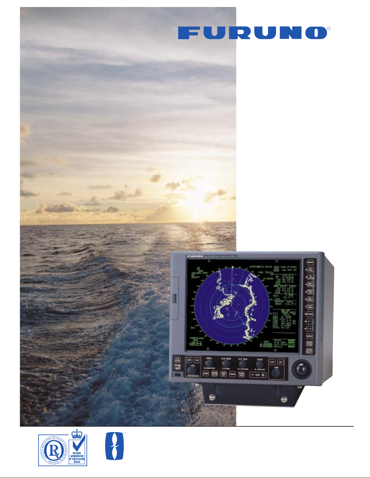
Models FR-1505/1510/1525 MARK-3
R
The future today with FURUNO's electronics technology.
FURUNO ELECTRIC CO., LTD.
9-52 Ashihara-cho, Nishinomiya City, Japan Telephone: +81 (0)798 65-2111
Telefax: +81 (0)798 65-4200, 66-4622, 66-4623
R
15-INCH MULTI-COLOR
HIGH-PERFORMANCE RADAR
TRADE MARK REGISTERED
MARCA REGISTRADA
Catalogue No. R-171b
■ Daylight-bright 15-inch multi-color,
high-resolution display
■ Logarithmic amplifier receiver
■ 16-level yellow or green display with day
and night color pallette
■ Dual EBLs and VRMs, with floating
origin
■ Head-Up, Course-Up, North-Up or Head-
up True Bearing and True Motion modes
■ True or relative echo trails
■ Two target alarm zones
■ 10-target Electronic Plotting Aid (EPA)
with true or relative vectors
■ Two user-programmable function keys
for one-touch optimized radar setting
■ Optional 20-target Auto Plotter ARP-17
(ATA)
■ Optional Video Plotter RP-17
■ Optional interface board to provide video
output for external monitor
■ Optional 42 rpm gearbox available
Page 2
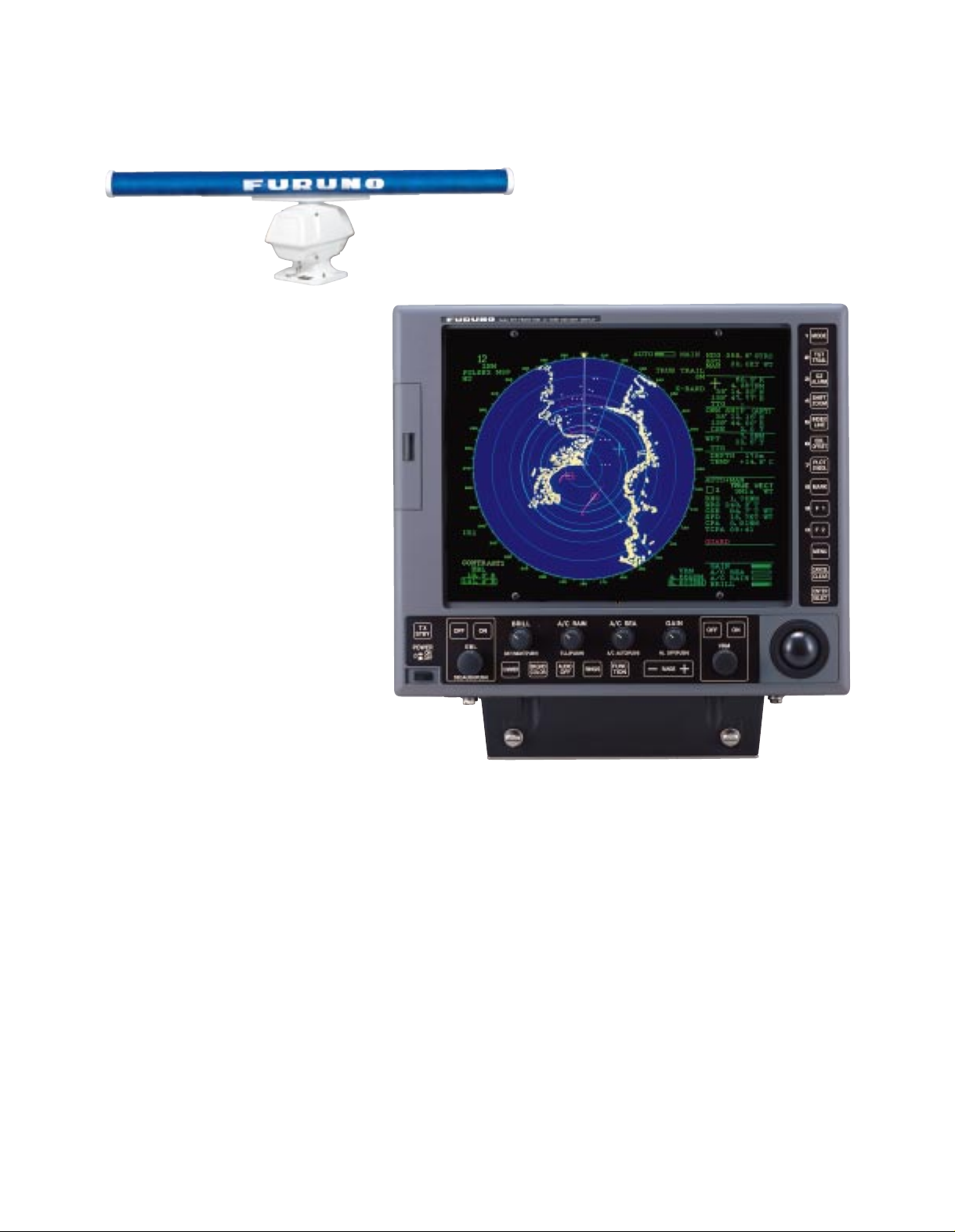
Advanced video processing techniques to
enhance detection capability on both short
and long ranges
shown on a 15-inch
high-resolution
display
The FURUNO FR-1505/1510/1525 MARK-3 X-band
radars will reinforce Furuno's long established
tradition of high performance and reliability. They
meet the exacting international and national
performance standards for use on ships requiring a
radar with the display diameter of 180 mm.
The Video Plotter RP-17 is available when Radar
Mapping function is also required.
The 1505/1510/1525 MARK-3 employ advanced
video processing techniques for improved noise
rejection and automatic clutter suppression.
They also feature clearly distinguished target trails
from real targets by different color tones and accurate
plotting, manually or automatically.
Five presentation modes are available: Head-up,
Course-up, North-up, Head-up true bearing and True
Motion with appropriate heading and speed data in
IEC 61162 format.
A wide choice of antenna types is offered to meet the
varying needs of individual installations. A highspeed scanner (42 rpm) is optionally available
instead of standard 24 rpm.
Standard features include dual VRMs/EBLs where
No.1 EBL may be off-centered and has a range
marker on it, true/relative target trails, echo stretch,
two target alarm zones, trackball for direct
range/bearing readout, EPA, quick restart of
transmission in case of accidental power-off, etc.
Two target alarm zones can be set in any sector at a
desired range. Visual and audible warnings are
produced to warn of a target entering the target alarm
zone or preset CPA/TCPA zone.
The standard EPA (Electronic Plotting Aid) permits
you to plot up to 10 targets. For SOLAS Convention
ships, the Auto Plotter ARP-17 (ATA) and Video
Plotter RP-17 are optionally available.
6.5 ft antenna
(4 or 8 ft available)
FR-1505 MARK-3: 6 kW
FR-1510 MARK-3: 12 kW
FR-1525 MARK-3: 25 kW
Complies with the following
regulations and standards
■ IMO Resolutions MSC. 64 (67)
Annex 4
■ IEC 60936-1 Shipborne radar
standard
■ IEC 60945 General
requirements
■ IEC 60872-2 ATA (Optional ARP-17 required)
Page 3

Target acquisition: Automatic or manual acquisition of up to
20 targets in 0.2-32 nm
Tracking range: 0.1-32 nm
Vector length: 0.5, 1, 3, 6, 15, 30 min, true or relative
Audio-visual alarm: Produced against lost targets and threatening
targets
Target data display: Range, bearing, course, speed and CPA/TCPA
of a chosen target
The Video Plotter RP-17 provides radar maps and storage of
navigation events on two IC cards - a memory card (RAM) for storing
the operator-created radar maps and a chart card (ROM) storing
FURUNO made digital charts. The memory card retains operatorcreated radar maps of a maximum of 3,000 points. A radar map is a
combination of map lines and symbols whereby the user can define
and input the navigation data, route planning and monitoring data.
The chart card (ROM) can drive the Electronic Reference Chart
(ERC) - digital chart published by the Japanese Hydrographic
Bureau. Nav lines, coastlines, buoys, etc. produced by operator by
3000 points in Radar mode, 6000 points with 98 waypoints and 10
routes on IC card in Chart mode at intervals of 0-30 s.
Provided with ship's heading and speed data, the FR-1505/1510/
1525 MARK-3 present true echo trails which permit intuitive
recognition of surrounding situation without smearing of stationary
targets, such as land. Relative echo trails are useful for identifying
a target on a collision course. The echo trails are displayed in
monotone or multilevel shading with a trail length selected between
15 s and 30 min, or continuously.
Radar Plotting Facilities
The new IMO Resolution defines 3 types of radar plotting
facilities: Electronic Plotting Aid (EPA), Automatic Tracking
Aid (ATA) and Automatic Radar Plotting Aid (ARPA).
All these Plotting Aids generate CPA and TCPA and
collision alerts, complying with all IMO and IEC standards.
The FR-1505/1510/1525 MARK-3 provide EPA and ATA*.
* with optional ARP-17
Electronic plotting of 10 targets according to the
new IMO and IEC standards. Automatically
redraw vectors between manual plots, drops off
vectors if not plotted more than 10 min as
required by IMO/IEC.
Powerful Standard Features
EPA (Electronic Plotting Aid)
Automatic Tracking Aid (ATA)
ARP-17 (Optional)
Video Plotter RP-17
(Optional)
Map area: 0.125 to 96 nm
Latitude limits: 85°N to 85°S
Plot interval: 0 to 30 s or 0 to 9,99 nm
Memory: Chart mode: 6000 points for track points and
marks, 98 waypoints, 10 routes.
Radar map mode: 3000 points
The Auto Plotter
ARP-17 automatically tracks up to
20 targets
acquired manually
or automatically,
presents target
data, and triggers
a collision alarm
for the target on a
collision course.
True or Relative Target Trails
Note: ARP-17 can be used for 24 rpm scanner only.
Page 4

ANTENNA RADIATOR
1. Type Slotted waveguide array
2. Beamwidth
Radiator type XN12AF XN20AF XN24AF
Length 4 ft 6.5 ft 8 ft
Beamwidth (H) 1.8° 1.23° 0.95°
Beamwidth (V) 25° 20° 20°
3. Rotation Speed 24 or 42 rpm
4. Wind load 100 knots relative wind
RF TRANSCEIVER
1. Frequency 9410 ± 30 MHz (X-band)
2. Output Power FR-1505 MARK-3: 6 kW
FR-1510 MARK-3: 12 kW
FR-1525 MARK-3: 25 kW
3. Pulselengths and Pulse Repetition Rates (PRR)
Range scales (nm) P/L (µs) PRR (Hz)
0.125, 0.25 0.07 3000
0.5 0.07/0.15 3000
0.75, 1.5 2 from 0.07/0.15/0.3 3000/1500
3 2 from 0.15/0.3/0.5/0.7 3000/1500
6 2 from 0.3/0.5/0.7/1.2 1500/1000
12, 24 2 from 0.5/0.7/1.2 1000/600
48, 96 1.2 600
4. Mixer and Local Oscillator Microwave integrated circuit (MIC)
5. Duplexer Ferrite circulator with diode limiter
6. IF 60 MHz, Logarithmic, BW 28/3 MHz
7. Noise Figure 6 dB
DISPLAY UNIT
1. Picture Tube 15-inch diagonal color CRT
Pixels: 1024 x 768 dots
Effective diameter: 185 mm
Echo color: Yellow or green echoes in 16 levels
2. Presentation
Head-up, Course-up*, North-up*, Head-up true bearing*,
True motion**
*Heading data required.
**Heading and speed data required.
3. Range Scales and Range Ring Intervals (nm)
Range: 0.125, 0.25, 0.5, 0.75, 1.5, 3, 6, 12, 24, 48, 96
Rings: 0.025, 0.05, 0.1, 0.25, 0.25, 0.5, 1, 2, 4, 8, 16
4. Minimum Range and discrimination
35 m
5. Accuracy
Range: 1% of range in use or 10 m, whichever is greater
Bearing: Better than 1°
6. Echo Trails
True or relative echo trails in monotone or multilevel shading (Speed
and heading data required for true echo trails)
Trail length: 15, 30 s, 1, 3, 6, 15, 30 min, or continuous
7. EPA (Electronic Plotting Aid)
Manual plotting of up to 10 targets with auto follow-up, true/rel
vectors with a specified vector length (30 s, 1, 3, 6, 15 or 30 min)
and target data readout (Speed and heading data required for true
vectors.)
8. Interface
Channel 1 Input: BWC, BWR, DBK, DBS, DBT, DPT, GGA, GLL,
HDG, HDM, MDA, MTW (*), RMA, RMB, RMC,
VBW, VTG, ZDA
Output: RSD (every 4 s),
TTL (When A/C RAIN control is pressed.)
Channel 2 Input: DBK, DBS, DPT, MDA, MTW, VBW
Output: TTM
Channel 3 Input: HDB, HDM, HDT, VHW
Output: None
9. Other Features
Automatic tuning, A/C sea/rain, Interference rejection, Second trace
echo suppression, Echo stretch, Heading line off (self-returning),
Two VRMs, Two EBLs with true/rel bearing readout*, EBL/VRM
offset, Instant day/night brilliance setting, Trackball cursor with range
and true/rel bearing* plus L/L** readouts, Parallel index lines, Offcentering (up to 75% of range scale), Quick restart in case of
accidental power-off, Nav data display**, User-definable function
key
*Heading data required for true bearing readout.
**Nav data inputs required.
ENVIRONMENTAL CONDITIONS
(Meets IEC 60945)
Temperature: -25°C to +70°C (Antenna unit)
-15°C to +55°C (Display unit)
POWER SUPPLY
12/24/32 VDC, 295 W max,or 115/230 VAC, 50/60 Hz, 1ø, 465 VA max.
440 VAC, 50/60 Hz with stepdown transformer RU-1803
(12 VDC for FR-1505/1510 MARK-3 only)
EQUIPMENT LIST
Standard
1. Display Unit RDP-119 with sun visor (DC or AC) 1 unit
2. Antenna Unit 1 unit
Scanner: RSB-0074 (24 rpm) or RSB-0075 (42 rpm)
Transceiver:RTR-067 (6 kW), RTR-062 (12 kW) or RTR-063 (25 kW)
3. Antenna Cable 15, 20, 30 m (specify) 1 pc.
4. Standard spare parts and installation materials 1 set
(Specify model number, power supply, antenna type and rpm, and length
of antenna cable when ordering.)
Optional
1. Power Cable CVV-S8x2C 15 m (for DC set)
2. Stepdown transformer RU-1803 (for 440 VAC, 50/60 Hz, 1ø mains)
3. External Alarm Buzzer OP03-21
4. Gyro Interface GC-8 (built-in type)
5. Gyro Converter AD-100
6. Video Plotter RP-17 (built-in type)
7. Auto Plotter ARP-17 (ATA)
For 24 rpm scanner only.
8. Performance Monitor PM-30
9. Handgrips
10.Interface Kit for connection of XGA monitor OP03-153
SPECIFICATIONS OF FR-1505/1510/1525 MARK-3
9910XXN Printed in Japan
FURUNO U.S.A., INC.
Camas, Washington, U.S.A.
Phone: +1 360-834-9300 Telefax: +1 360-834-9400
FURUNO (UK) LIMITED
Denmead, Hampshire, U.K.
Phone: +44 2392-230303 Telefax: +44 2392-230101
FURUNO FRANCE S.A.
Bordeaux-Mérignac, France
Phone: +33 05 56 13 48 00 Telefax: +33 05 56 13 48 01
FURUNO ESPAÑA S.A.
Madrid, Spain
Phone: +34 91-725-90-88 Telefax: +34 91-725-98-97
FURUNO DANMARK AS
Hvidovre, Denmark
Phone: +45 36 77 45 00 Telefax: +45 36 77 45 01
FURUNO NORGE A/S
Ålesund, Norway
Phone: +47 70 102950 Telefax: +47 70 127021
FURUNO SVERIGE AB
Västra Frölunda, Sweden
Phone: +46 31-7098940 Telefax: +46 31-497093
FURUNO SUOMI OY
Helsinki, Finland
Phone: +358 9 317277 Telefax: +358 9 3412930
SPECIFICATIONS SUBJECT TO CHANGE WITHOUT NOTICE
470 18.5"
4-˘15
300 11.8"
(240 9.5")
XN20AF: 2060 81.1"
XN12AF: 1250 49.2"
XN24AF: 2570 101.2"
570 22.4"
DISPLAY UNIT
ANTENNA UNIT
2C 1.5 m
250V-DPYCY-1.25
SDME
CO-SPEVV-SB-C
Gyro
Compass
250V-MPYCY-5
Performance Monitor
PM-30 (option)
CO-SPEVV-SB-C
EPFS
ANTENNA UNIT
Gyro Interface
* 24 rpm, 12/24/32 VDC or 115/230 VAC
(for FR-1505/1510 MARK-3)
Auto Plotter
ARP-17
Video Plotter
RP-17
DISPLAY UNIT
External Buzzer
Gyro
Converter
Optional Supply
* Specify when ordering
24 rpm, 24/32 VDC or 115/230 VAC
(for FR-1525 MARK-3)
* 42 rpm, 24/32 VDC or 115/230 VAC
(for FR-1505/1510/1525 MARK-3)
Stepdown
Transformer
RU-1803
440 VAC
INTERCONNECTION DIAGRAM
200 7.9"
51 2.0"
465 18.3"
355 14.0"
412 16.2"
4-˘12
422 16.6"
487 19.2"
134 5.3" 200 7.9"
611 24.1"
29 kg, 64 lb
RSB-0074/RTR-067/XN12AF:
31 kg 68 lb
RSB-0074/RTR-062/XN20AF:
37 kg 82 lb
RSB-0074/RTR-063/XN24AF:
40 kg 88 lb
 Loading...