


 Loading...
USER’S MANUAL
WIDE PLASMA DISPLAY P42HTS51E P50XTS51E P55XTS51E
AV SELECTOR FOR WIDE PLASMA DISPLAY P-TU4251E P-TU5051E P-TU5551E
Français Español Deutsch English
Contents
|
Page |
Before Use |
|
• INFORMATION............................................................ |
E-2 |
• INSTALLATION ........................................................... |
E-4 |
Usage |
|
• PART NAMES AND FUNCTIONS ............................... |
E-5 |
• USING THE REMOTE CONTROL ............................ |
E-12 |
• CONNECTING THE DISPLAY TO EXTERNAL |
|
EQUIPMENT.............................................................. |
E-14 |
• BASIC OPERATIONS................................................ |
E-24 |
• SELECTING INPUT MODE ....................................... |
E-26 |
• OTHER BASIC OPERATIONS .................................. |
E-29 |
• WATCHING PICTURES ON THE WIDE SCREEN ... |
E-30 |
Adjustments |
|
• ADJUSTMENT MENU ............................................... |
E-32 |
• BASIC PROCEDURE OF ADJUSTMENT MENU |
|
OPERATIONS ........................................................... |
E-33 |
• ADJUSTING THE PICTURE...................................... |
E-34 |
• ADJUSTING SCREEN POSITION AND SIZE........... |
E-36 |
• ADJUSTING AUDIO .................................................. |
E-37 |
|
Page |
• OTHER ADJUSTMENTS ........................................... |
E-38 |
• INITIALIZATION OF USER ADJUSTMENT VALUE.. |
E-44 |
Others |
|
• OPTIONS ................................................................... |
E-45 |
• MAIN SUPPORTED SIGNALS .................................. |
E-46 |
• TABLE OF TV FREQUENCIES ................................. |
E-47 |
• SPECIFICATION........................................................ |
E-48 |
• CLEANING AND MAINTENANCE ............................. |
E-50 |
Before using the display, read this manual carefully so that you know how to use the display correctly.
Refer to this manual whenever questions or problems about operation arise. Be sure to read and observe the safety precautions (see the separate “Safety Precautions” manual).
Keep this manual where the user can see it easily.
*Installation and removal require special expertise. Consult your product dealer for details.
*When “English” is selected at “Language” of the on-screen display, “colour” will be displayed but “color” is described in this manual.
*The last digit of MODEL NO. (10 digit alphanumeric characters) indicated on the product means the body color indication alphabet or the management number.
Pусский Português Italiano

INFORMATION
•Receptacle
Make sure that the power cord’s grounding wire is grounded.
The plasma display comes with a 3-prong power plug; one prong is connected to the grounding wire. If you have only a 2-hole receptacle, you will need to have it replaced. Contact your dealer for more information.
•Have the plasma display inspected and cleaned by your dealer at regular intervals.
•Pictures may become “burn-in” into the screen phosphors if the screen left on with same picture or pattern for extended periods of time. To ensure that the plasma display has a prolonged service life, be sure to use settings such as the screen orbiter or white screen settings. These settings will ensure that the same picture or pattern is not constantly displayed for long periods. (See P. E-42 )
•High-precision technology has been used in the manufacture of the plasma display panel, in which the effective pixels exceeds 99.99%. However, please be aware, that fewer than 0.01% of the pixels may be missing or remain constantly lit.
•Some models are fitted with a radiator fan to prevent the plasma display’s internal temperature from rising during operation. Be careful of the air emitted by the radiator fan, as it may be hot.
•Contact your dealer when causing a bad influence to the plasma display and other audio-visual equipment mutually.
You may need to move your plasma display if it produces degraded pictures or noise due to electromagnetic radiation, or if the infrared remote control does not function properly.
•Pictures may not be displayed properly if you connect a non-standard PC to the RGB input terminal. In this case, contact your dealer for more information.
•The protective circuit, built into the display, automatically turns off the power if the display has a problem. In this case, you will see that the power indicator lamp flashes red or green.
Warning
If the power indicator lamp flashes red or green, this signifies that the display has developed a problem. When this happens, be sure to unplug from the receptacle to prevent fire or electric shock. Then contact your dealer.
•It is important to install the plasma display in a location close to a receptacle, and where the emergency stop button can be easily reached.
Note
•Cables for connecting the display to external equipment are not supplied. Contact your dealer for more information on these products.
•In order to facilitate the explanations, pictures and diagrams in this manual may differ slightly from the actual items.
E-2
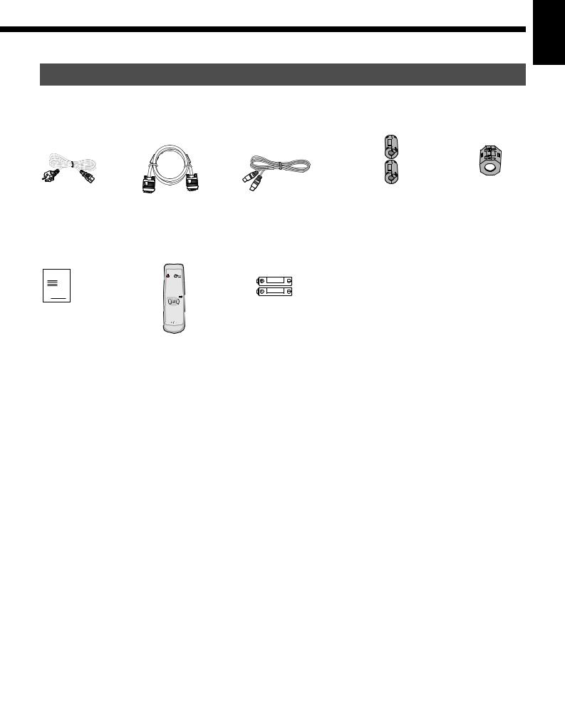
ACCESSORIES
Display Section
One power cable |
One System cable |
One System cable |
Two small ferrite cores |
One big ferrite core |
||||
|
(picture) |
(audio) |
|
|
|
|
|
|
|
|
|
|
|
|
|
|
|
|
|
|
|
|
|
|
|
|
|
|
|
|
|
|
|
|
|
|
|
|
|
|
|
|
|
|
|
|
|
|
|
|
|
|
|
|
|
|
|
|
|
|
|
|
|
|
|
|
|
|
|
|
|
|
|
|
|
|
|
|
|
|
|
|
|
No.:ZCAT1518-0730 |
No.:SFT-72SN |
|
|
|
Mfr.:TDK |
Mfr.:TKK |
AV Selector Section |
|
|
|
|
Two user's manuals |
One remote control |
Two AA batteries |
One power cable |
One big ferrite core |
Manual Manual
No.:SFT-72SN
Mfr.:TKK
Pусский Português Italiano Français Español Deutsch English
E-3

INSTALLATION
To prevent the plasma display’s internal components from overheating, make sure that the plasma display is installed in a well-ventilated location.
Be sure to use the optional stand, wall-mounting unit or the other mounting unit when installing the plasma display. Also, be sure that your dealer performs the installation.
See the appropriate instruction manual for additional information on the mounting hardware you select.
To prevent an accident and ensure safety in the event of an earthquake, fix the plasma display securely into the position as described below.
Use the diagram below to determine how much space is needed to ensure proper heat radiation. This is a minimum space requirement; therefore, provide at least as much space as indicated below.
*Make sure that the plasma display is installed in a location where the temperature can be maintained between 0°C and 40°C (between 32°F and 104°F).
*Never attempt to tilt the plasma display sideways or backward.
*To prevent the power cord and other cables from being accidentally pulled, make sure that they run along the wall or through corners.
*To prevent accidents and ensure safety in the event of an earthquake, secure the plasma display to prevent it from tipping over.
Display Section |
(cm) |
(cm) |
|
|
Front |
|
|
Side |
Upper |
|
|
|
10 |
|
|
|
10 |
10 |
Right |
Wall |
Left |
|
|
|
5 |
|
|
|
Lower |
|
|
3.5 (for 42” / 50”) |
|
|
|
|
|
|
|
5 (for 55”) |
AV Selector section
|
Front |
Side |
|
(cm) |
(cm) |
|
Upper |
Upper |
|
|
|
Left |
Right |
Rear |
|
||
|
Floor |
Floor |
Note
•See P. E-45 for details on the options.
•The external view is meant to be a representation of the actual unit and is not to scale; therefore, it may differ from the actual shape and size of the product.
•Due to the fragile and highly precise equipment, it is very important to pack properly before transportation using only the packing materials provided.
E-4
PART NAMES AND FUNCTIONS
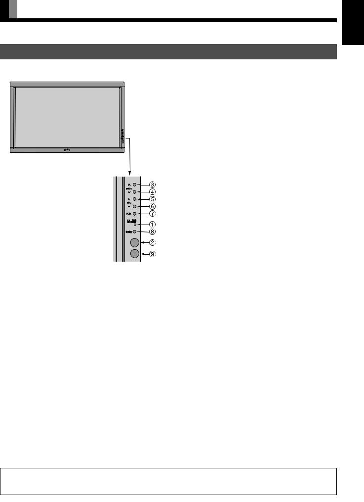
DISPLAY SECTION – FRONT
Power indicator lamp
This lamp shows the state of the power supply.
Lit (red): |
Stand-by state |
Lit (green): |
Power ON state |
Flashing (red or green): |
Malfunction (Flashes differently |
|
depending on the type of |
|
malfunction.) |
Remote control signal receiver
Receives signals from the remote control.
Input mode selector button  Input mode selector button
Switches the input modes (Video mode, RGB mode and TV mode).
Volume + buttonVolume - button
Adjusts the audio volume.
Wide screen selector button
Switches the screen over to a desired wide screen.
ON/OFF button
Turns the power “ON” and “OFF (standby state)”.
Ambient Sensor
Detects the brightness of ambient light.
It is important not to obstruct it for full functionality of the feature.
Warning
If the power indicator lamp flashes red or green, this signifies that the display has developed a problem. When this happens, be sure to remove the power plug from the receptacle and contact your dealer. Leaving the display power ON can result in fire or electric shock.
E-5
Pусский Português Italiano Français Español Deutsch English
PART NAMES AND FUNCTIONS (Continued)
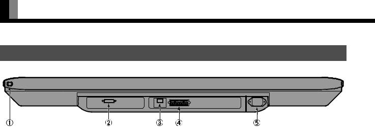
DISPLAY SECTION – LOWER PART
/l power switch
If this button is pressed when the power indicator lamp is off, the indicator lamp will light.
The power can be turned on and the standby mode selected by using the remote control or the control panel of the display. If this button is pressed when the power indicator lamp is lit, the indicator lamp will go out.
*Power is still supplied to parts of the display even if the indicator lamp is off.
Display input (picture) terminal
Connect this terminal to the display output (picture) terminal on the AV Selector using the special cable provided.
Display input (audio) terminal
Connect this terminal to the display output (audio) terminal on the AV Selector using the special cable provided.
External speaker output terminal (EXT SP)
Connect this terminal to the optionally available speaker.
When connecting a cable, attach a ferrite core to the cable. (See P. E-14.) *See the speaker user’s manual for more information.
Power input terminal
Connect this terminal to the power cord supplied with the display. When connecting a cable, attach a ferrite core to the cable. (See P. E-14.)
E-6
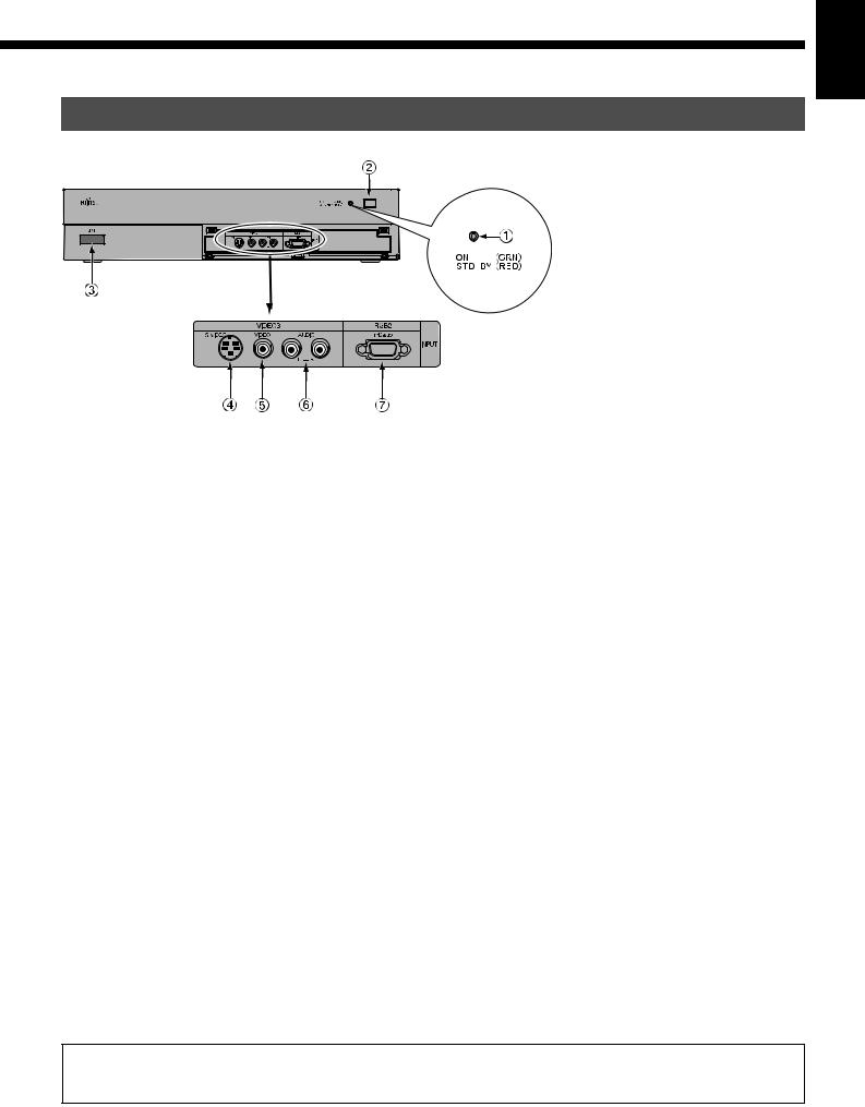
AV SELECTOR SECTION – FRONT
Power indicator lamp
This lamp shows the state of the power supply.
Lit (red): |
Stand-by |
Lit (green): |
Power ON |
Flashing (red or green): Malfunction (Flashes differently depending on the type of malfunction.)
Remote control signal receiver
Receives signals from the remote control.
/l power switch
If this button is pressed when the power indicator lamp is off, the indicator lamp will light.
The power can be turned on and the standby mode selected by using the remote control or the control panel of the display. If this button is pressed when the power indicator lamp is lit, the indicator lamp will go out.
*Power is still supplied to parts even if the indicator lamp is off.
Video3, S-video input terminal *
Connect this terminal to the S-video output terminal of your video camera, etc.
Video3, video input terminal *
Connect this terminal to the video output terminal of your video camera, etc.
Audio input terminals (L/R)
These are the audio input terminals for the Video3 and RGB2 terminals.
Input the audio for the video to be seen here.
RGB2 input terminal
Connect this terminal to the output terminal of a PC, set-top box, game, etc.
* On selecting the video input format
(See “SETTING THE INPUT TERMINALS” on P. E-40.)
Warning
If the power indicator lamp flashes red or green, this signifies that the display has developed a problem. When this happens, be sure to remove the power plug from the receptacle and contact your dealer. Leaving the display power ON can result in fire or electric shock.
Pусский Português Italiano Français Español Deutsch English
E-7
PART NAMES AND FUNCTIONS (Continued)
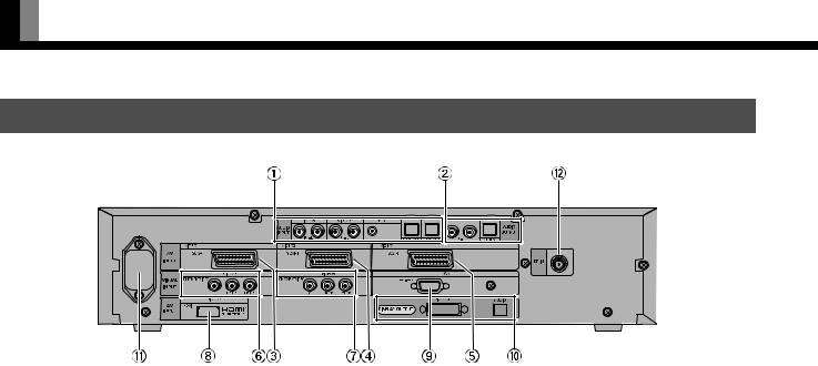
AV SELECTOR SECTION – REAR
Audio input terminals
Input audio through the terminals corresponding to the used video input terminals.
*The digital input terminals can be matched as desired with the remote control. (See P. E-29.)
Audio output terminals
For use when the audio from an audio system (amplifier) is used.
Video1 input terminalVideo2 input terminal
Video4 input terminal
Connect this terminal to the SCART terminal of your VCR or DVD, etc.
*See “SETTING THE INPUT TERMINALS” on P. E-40.
Video5 input terminal
Video6 input terminal
Connect this terminal to the Component Video Output terminal of DVD recorder/player or satellite receiver.
Video7 input terminal
Connect this terminal to the HDMI output terminal of DVD recorder/player or other video source.
RGB1 input terminal
Connect this terminal to the output terminal of a PC, set-top box, game, etc.
Display output terminals (Picture/Audio)
Connect these terminals to the picture input terminal and audio input terminals on the display.
Power input terminal
Connect this terminal to the power cord supplied with the display.
When connecting a cable, attach a ferrite core to the cable. (See P. E-14.)
Antenna input terminal
Please connect it to the antenna signal.
E-8
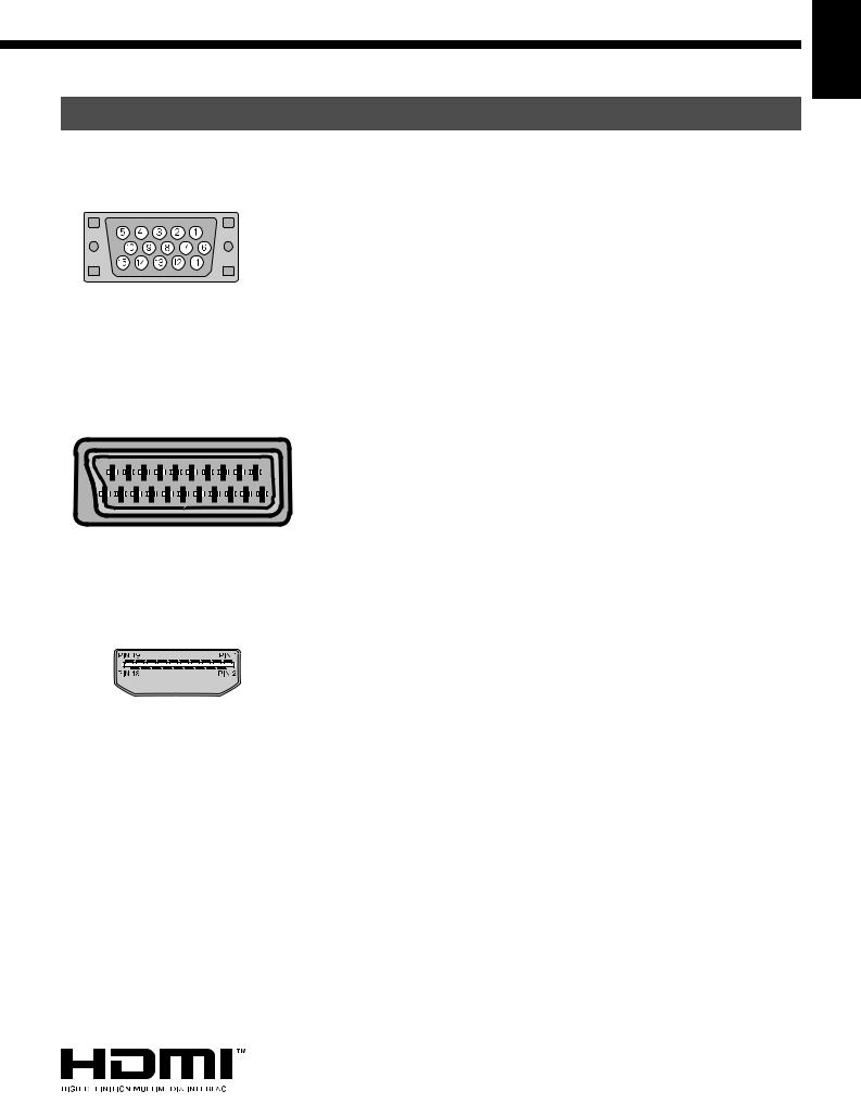
DESCRIPTION OF INPUT TERMINALS
mD-sub input terminal (RGB1, 2 INPUT/mD-sub)
SCART terminal (Video1, 2, 4)
201816141210 8 6 4 2
211917151311 9 7 5 3 1
HDMI input terminal (VIDEO7)
Pin No. |
|
Input signal |
Pin No. |
Input signal |
|
|
|
|
|
1 |
Red |
|
9 |
— |
|
|
|
|
|
2 |
Green |
|
10 |
Ground |
|
|
|
|
|
3 |
Blue |
|
11 |
— |
|
|
|
|
|
4 |
— |
|
12 |
— |
|
|
|
|
|
5 |
Ground |
|
13 |
Horizontal synchronization |
|
|
|
|
|
6 |
Ground |
|
14 |
Vertical synchronization |
|
|
|
|
|
7 |
Ground |
|
15 |
— |
|
|
|
|
|
8 |
Ground |
|
Frame |
Ground |
|
|
|
|
|
Pin No. |
Input Signal |
Pin No. |
Input Signal |
Pin No. |
Input Signal |
|
|
|
|
|
|
1 |
— |
8 |
— |
15 |
Red/chrominance |
|
|
|
|
|
|
2 |
Right audio |
9 |
Green ground |
16 |
— |
|
|
|
|
|
|
3 |
— |
10 |
— |
17 |
— |
|
|
|
|
|
|
4 |
Audio ground |
11 |
Green |
18 |
Composite video ground |
|
|
|
|
|
|
5 |
Blue ground |
12 |
— |
19 |
— |
|
|
|
|
|
|
6 |
Left audio |
13 |
Red ground |
20 |
Composite video/Y |
|
|
|
|
|
|
7 |
Blue |
14 |
— |
21 |
Ground |
|
|
|
|
|
|
Pin No. |
Input signal |
Pin No. |
Input signal |
|
|
|
|
1 |
T.M.D.S. Data2+ |
11 |
T.M.D.S. Clock Shield |
|
|
|
|
2 |
T.M.D.S. Data2 Shield |
12 |
T.M.D.S. Clock– |
|
|
|
|
3 |
T.M.D.S. Data2– |
13 |
CEC |
|
|
|
|
4 |
T.M.D.S. Data1+ |
14 |
Reserve |
|
|
|
|
5 |
T.M.D.S. Data1 Shield |
15 |
DDC Clock |
|
|
|
|
6 |
T.M.D.S. Data1– |
16 |
DDC Data |
|
|
|
|
7 |
T.M.D.S. Data0+ |
17 |
Ground (for +5V) |
|
|
|
|
8 |
T.M.D.S. Data0 Shield |
18 |
+5V Power |
|
|
|
|
9 |
T.M.D.S. Data0– |
19 |
Hot Plug Detect |
|
|
|
|
10 |
T.M.D.S. Clock+ |
Frame |
FG |
|
|
|
|
Pусский Português Italiano Français Español Deutsch English
HDMI, the HDMI logo and High-Definition Multimedia interface are trademarks or registered trademarks of HDMI Licensing LCC.
E-9
PART NAMES AND FUNCTIONS (Continued)
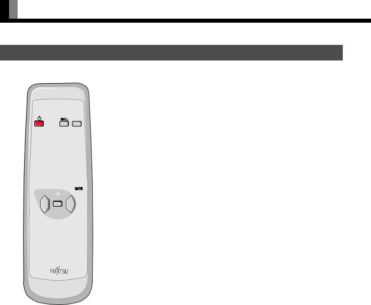
REMOTE CONTROL
For details, see page Î.
(POWER button) Î E-24
Switches between Power On and Standby.
,(STILL button) Î E-29
Displays the screen being watched as the still picture. To return to normal, press this button once again.
(WIDE button) Î E-30
Switches the screen size.
(TV input mode selector button) Î E-26
Press this button to watch terrestrial broadcastings.
(Video input mode selector button) Î E-28
Press this button to switch through VIDEO1 to VIDEO7.
(RGB input mode selector button) Î E-28
Press this button to switch through RGB1 to RGB2.
.(TELETEXT input mode selector button) Î E-27
Press this button to switch to the teletext broadcastings. (selectable only when watching the TV.)
– (Number buttons) Î E-26
Use these buttons for the Program No. selection directly.
In the teletext broadcastings, input the 3 digits for the required teletext page to change the page.
/0(Channel Up/Down buttons) Î E-26
Press these buttons to select the preset programs.
Use these buttons to scroll through a page in the teletext broadcasting.
12(Volume adjustment buttons) Î E-25
Press these buttons to adjust the volume.
6(AUDIO IN button) Î E-29
Press this button to select the audio input.
:(Channel Return button) Î E-26
Returns to the previous Program No. and input mode immediately.
" ;(MENU button) Î E-32–E-44
Press this button to display the menu screen for adjusting the picture and/or the audio.
# -(MUTE button) Î E-25
Temporarily mutes the audio.
To return the audio to normal, press this button once again, or press the 1does the 2work also.
$ CDEF
Use these buttons to select the item or adjust the value in the Menu screen.
Use these buttons to scroll through the pages and switch among the LIST pages in the teletext broadcasting. (Only EFare used when switching LIST pages.)
E-10
% <(ENTER button) Î E-32–E-44
Press this button to fix the entry in the ADJUSTMENT MENU.
& G(DUAL/STEREO button) Î E-29
Press this button to select the audio mode for stereo/dual-channel audio broadcasting.
' KLMN(COLOR button) Î E-27
In the teletext broadcasting, press these buttons to switch through the pages stored to each of the four colors in the LIST mode. Other than the LIST mode, these buttons can also be used for the colored option selected from the four teletext new options displayed at the bottom of the screen.
( O(SUBPAGE button)
Press this button to display the SUBPAGE.
) P(REVEAL button)
Press this button to display hidden text (such as the answers to quizzes ,etc.).
* R(HOLD button)
Press this button to hold the transmission of the teletext program you are currently watching.
+ Q(SIZE button)
Press this button to change the size of the current watching page.
, S(INDEX button)
Press this button to return to the INDEX page.
- T(MODE button)
Switches to the LIST mode. Press this button once again to return to the current mode.
. V(STORE button) Î E-27
In LIST mode, saves the current display to the Favorites page.
/ U(CANCEL button)
Press this button to watch the CANCEL page.
Press it once again to return to the teletext broadcasting you were watching before you pressed U.
0 3(DISPLAY button) Î E-29
Press this button to display the Program No., input mode, and screen size status. The status is displayed for about five seconds.
1 4(PICTURE MODE button) Î E-29
Use this button to switch the Picture Mode.
2 7(OFF-TIMER) Î E-29
Use this button to specify the length of time until the power turns off (stand-by state) after the button is pressed.
3 5(PICTURE MEMORY button) Î E-29
Press this button to access the Picture Memory.
Note
• Functions may not be available with some models and some device options.
Pусский Português Italiano Français Español Deutsch English
E-11
USING THE REMOTE CONTROL
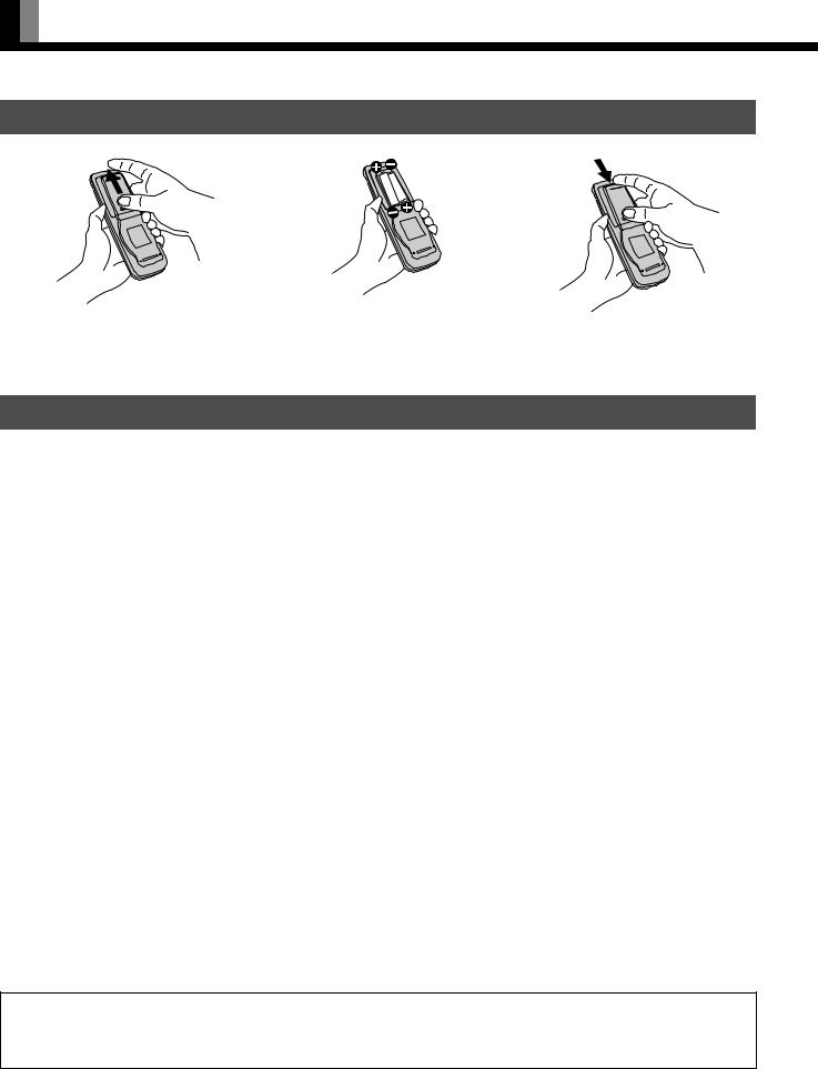
PUTTING BATTERIES IN THE REMOTE CONTROL
(1)To remove the cover, slide it outwards while pressing it down.
(2) Place two AA batteries in the remote |
(3) Close the cover until it snaps into place. |
control. Make sure that the batteries are |
|
properly oriented. |
|
PRECAUTIONS
To prevent malfunction, be sure not to apply any form of severe shock to the remote control.
To prevent malfunction or deformation, be sure not to allow the remote control to become wet; also, keep it away from hot locations or heating equipment.
Be sure not to clean the remote control using a cloth dampened in any volatile solvent, such as benzene or thinner.
CAUTION
It is very important to use replacement batteries of the same type as the originally used. Do not use rechargeable batteries (Ni-Cd, etc.).
When disposing of used batteries, please comply with governmental regulations or environmental public institution’s rules that apply in your country/ area.
Note
The remote control will not function properly if the batteries are dead. Be sure to replace them as needed.
E-12
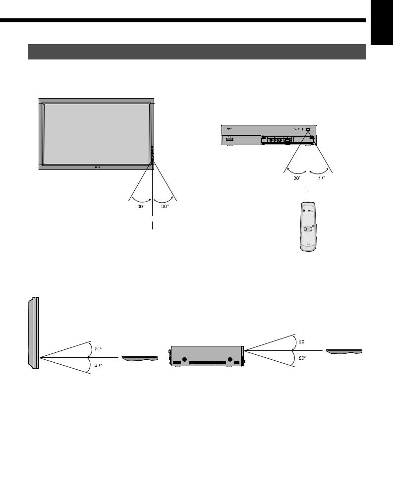
EFFECTIVE RANGE FOR THE REMOTE CONTROL
Point the remote control at the display’s signal receiver when using it.
Make sure that there are no obstacles between the remote control and the display’s signal receiver.
Left |
Right |
|
5 m (Front) |
Left |
Right |
5 m (Front)
Display – front
Upper
Upper
Lower
Lower
Display – side
Note
The remote control may not function properly if you use a high-frequency fluorescent lamp. If you experience problems, move the lamp or use the remote control from a different position.
Do not use rechargeable batteries (Ni-Cd, etc).
Pусский Português Italiano Français Español Deutsch English
E-13
CONNECTING THE DISPLAY TO EXTERNAL EQUIPMENT
Be sure to turn OFF the power to the display and external equipment before making any connections.
No cables are supplied with the display for connection to external equipment. The type of cable to be used varies depending on the PC model. Contact your dealer for more information.
Carefully check the terminals for position and type before making any connections.
Loose connectors can result in picture or color problems. Make sure that all connectors are securely inserted into their terminals.
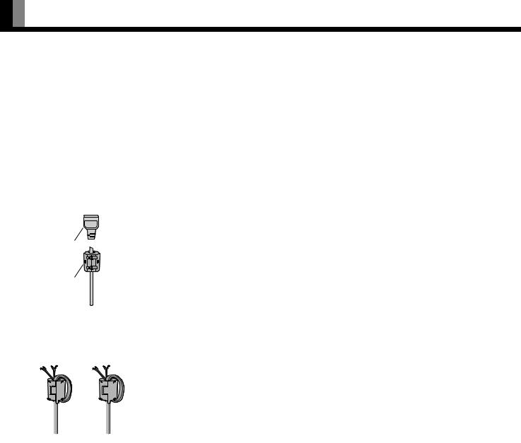
These ferrite cores are used to attenuate undesired signals. Attach them correctly as shown in the following illustrations.
Two big ferrite cores (For Display and AV SELECTOR)
When connecting a cable to the power input terminal attach one of these ferrite cores to the cable near the terminal.
Power Cable 
Ferrite Core
Two small ferrite cores
When connecting a cable to the external speaker output terminal, attach a ferrite core to the cable near the terminal as illustrated on the right.
E-14
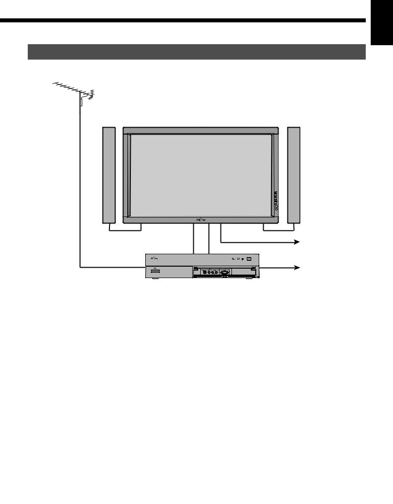
BASIC SYSTEM CONNECTIONS
Antenna (commercially available product)
|
|
Display |
Speaker (optional) |
|||
|
|
|
|
|
|
|
|
|
|
|
|
|
|
|
|
|
|
|
|
|
|
|
|
|
|
|
|
To AC outlet
To AC outlet
AV Selector
1.Connect the following items to the AV Selector and the display
(1) AV Selector and display
Connect these two with the provided system connection cable. (For details, see page E-16.)
(2) Antenna line
See page E-17 for further details.
(3) Speakers
For how to connect speakers, see the instructions provided with the speakers.
2.Connecting the power cord
• Connect the power plug of the display and AV Selector power cords to a grounded 3-pin outlet.
Pусский Português Italiano Français Español Deutsch English
E-15
Loading...