


FUJITSU PDS5003W-H, PDS5003W-S, PDS5003E-S, PDS5003E-H, PDS5003U-S Service Manual
...PDS5003W-H/S PDS5004W-S
PDS5003E-H/S PDS5004E-S
PDS5003U-H/S PDS5004U-S
F U J I T S U G E N E R A L P r o p r i e t a r y
C o p y P r o h i b i t e d
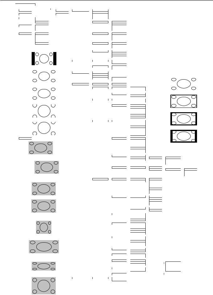
VIDEO MODE ADJUSTMENT
REMOTE CONTROLLER |
|
|
|
|
|
|
|
|
|
|
|
|
|
|
|
|
|
|
|
|
|
|
|
||||||||||
|
|
POWER ON |
|
|
|
|
MENU |
|
|
PICTURE |
|
|
Contrast |
{-30 to +30} |
|
|
|
|
|
|
|
|
|
|
|
|
|
|
|
||||
|
|
|
|
|
|
|
|
|
|
|
|
|
|
|
Brightness |
{-60 to +60} |
|
|
|
|
|
|
|
|
|
|
|
|
|
|
|
||
|
|
POWER OFF |
|
|
|
|
ENTER |
|
|
|
|
Color |
{-60 to +60} |
|
|
|
|
|
|
|
|
|
|
|
|
|
|
|
|||||
|
|
|
|
|
|
|
|
|
|
|
|
|
|
|
|
|
|
|
|
|
|
|
|
|
|||||||||
|
|
|
|
|
|
|
|
|
|
|
|
|
|
|
Tint |
{-30 to +30 (Comp. Video -60 to +60)} |
|
|
|
|
|
|
|
|
|
|
|
|
|||||
|
|
|
|
|
|
|
|
|
|
|
|
|
|
|
|
|
|
|
|
|
|
|
|
|
|
|
|||||||
|
|
RGB |
|
RGB 1 |
|
|
|
|
|
|
|
|
Sharpness |
{-16 to +16} |
|
|
|
|
|
|
|
|
|
|
|
|
|
|
|
||||
|
|
|
|
|
|
RGB 2 |
|
|
|
|
|
|
|
|
|
|
|
|
|
|
|
|
|
|
|
|
|
|
|
|
|
|
|
|
|
|
|
|
|
RGB 3 |
|
|
|
|
|
|
|
|
Picture Mode |
|
|
Dynamic |
|
|
|
|
|
|
|
|
|
|
|
|
|
|
|
|
|
|
|
|
|
|
|
|
|
|
|
|
|
|
|
|
|
Fine |
|
|
|
|
|
|
|
|
|
|
|
|
|
|
|
|
|
VIDEO |
|
Video |
|
|
|
|
|
|
|
|
|
|
|
Real 1 |
|
|
|
|
|
|
|
|
|
|
|
|
|
|
|
||
|
|
|
|
|
|
S-Video |
|
|
|
|
|
|
|
|
|
|
|
Real 2 |
|
|
|
|
|
|
|
|
|
|
|
|
|
|
|
|
|
|
|
|
|
Comp. Video |
|
|
|
|
|
|
|
|
|
|
|
Static |
|
|
|
|
|
|
|
|
|
|
|
|
|
|
|
|
|
|
|
|
|
|
|
|
|
|
|
|
|
|
|
|
|
|
|
|
|
|
|
|
|
|
|
|
|
|
|
||
|
|
WIDE |
|
Normal |
|
|
|
|
|
|
|
|
Color Temp. |
|
|
Standard |
|
|
|
|
|
|
|
|
|
|
|
|
|
|
|
||
|
|
|
|
|
|
Auto |
|
|
|
|
|
|
|
|
|
|
|
Cool |
|
|
|
|
|
|
|
|
|
|
|
|
|
|
|
|
|
|
|
|
|
|
|
|
|
|
|
|
|
|
|
|
|
|
|
|
|
|
|
|
|
|
|
|
|
|
|
||
|
|
|
|
|
|
Wide 1 |
|
|
|
|
|
|
|
|
|
|
|
User |
|
|
|
|
|
|
|
|
|
|
|
|
|
|
|
|
|
|
|
|
|
|
|
|
|
|
|
|
|
|
|
|
|
|
|
|
|
|
|
|
|
|
|
|
|
|
|
||
|
|
|
|
|
|
Wide 2 |
|
|
|
|
|
|
|
|
|
|
|
Warm |
|
|
|
|
|
|
|
|
|
|
|
|
|
|
|
|
|
|
|
|
|
|
|
|
|
|
|
|
|
|
|
|
|
|
|
|
|
|
|
|
|
|
|
|
|
|
|
||
|
|
|
|
|
|
Zoom 1 |
|
|
|
|
|
|
|
|
|
|
|
|
|
|
|
|
|
|
|
|
|
|
|
|
|
|
|
|
|
|
|
|
|
|
|
|
|
|
|
|
|
|
|
|
|
|
|
|
|
|
|
|
|
|
|
|
|
|
|
|
|
|
|
|
|
|
|
Zoom 2 |
|
|
|
|
|
|
|
|
User Color Temp. |
|
|
Red |
{0 to 255} |
|
|
|
|
|
|
|
|
|
|
|
|
||
|
|
|
|
|
|
|
|
|
|
|
|
|
|
|
|
|
|
Green |
{0 to 255} |
|
|
|
|
|
|
|
|
|
|
|
|
||
|
|
|
|
|
|
|
|
|
|
|
|
|
|
|
|
|
|
Blue |
{0 to 255} |
|
|
|
|
|
|
|
|
|
|
|
|
||
|
|
|
|
|
|
|
|
|
|
|
|
|
|
|
|
|
|
|
|
|
|
|
|
|
|
|
|
|
|
||||
|
|
|
|
|
Normal |
|
|
|
|
Noise Reduction |
|
|
Std |
|
|
|
|
|
|
|
|
|
|
|
|
|
|
|
|||||
|
|
|
|
|
|
|
|
|
|
|
|
|
|
|
|
|
|
Max |
|
|
|
|
|
|
|
|
|
|
|
|
|
|
|
|
|
|
|
|
|
|
|
|
|
|
|
|
|
|
|
|
|
|
|
|
|
|
|
|
|
|
|
|
|
|
|
|
|
|
|
|
|
|
|
|
|
|
|
|
|
|
|
|
|
|
|
Off |
|
|
|
|
|
|
|
|
|
|
|
|
|
|
|
|
|
|
|
|
|
|
|
|
|
|
|
|
|
|
|
|
|
|
|
|
|
|
|
|
|
|
|
|
|
|
|
|
|
|
|
|
|
|
|
|
|
|
|
|
|
|
|
|
|
|
|
Min |
|
|
|
|
|
|
|
|
|
|
|
|
|
|
|
|
|
|
|
|
|
|
|
|
|
|
|
|
|
|
|
|
|
|
|
|
|
|
|
|
|
|
|
|
|
|
|
|
|
|
|
|
|
|
|
|
|
|
|
|
|
POSITION/SIZE |
|
|
Position |
|
|
Horizontal |
{-30 to +30 (Comp. Video -16 to +16) (1080I,720P -32 to +32)} |
|
|
|
|||||||||||
|
|
|
|
|
|
|
|
|
|
|
|
|
|
|
|
|
|
Vertical |
{-7 to +7 (Zoom:-15 to +15) (Comp. Video -16 to +16) (1080I,720P -32 to +32)} |
||||||||||||||
|
|
|
|
|
|
|
|
|
|
|
|
|
|
|
Size |
|
|
Width |
{-7 to +7 (Comp. Video -4 to +4)} |
|
|
|
|
|
|
|
|
||||||
|
|
|
|
|
|
|
|
|
|
|
|
|
|
|
|
|
|
|
|
|
|
|
|
|
|||||||||
|
|
|
|
|
Wide 1 |
|
|
|
|
|
|
|
Height |
{-7 to +7 (Comp. Video -4 to +4)} |
|
|
|
|
|
|
|
|
|||||||||||
|
|
|
|
|
|
|
|
|
|
|
|
|
|
|
|
|
|
|
|
||||||||||||||
|
|
|
|
|
|
|
|
|
|
|
|
AUDIO |
|
|
Treble |
{-6 to +6} |
|
|
|
|
|
|
|
|
|
|
|
|
|
|
|
||
|
|
|
|
|
|
|
|
|
|
|
|
|
|
|
Bass |
{-6 to +6} |
|
|
|
|
|
|
|
|
|
|
|
|
|
|
|
||
|
|
|
|
|
|
|
|
|
|
|
|
|
|
|
Balance |
{-10 to +10} |
|
|
|
|
|
|
|
|
|
|
Mask Off |
|
|
|
|||
|
|
|
|
|
|
|
|
|
|
|
|
|
|
|
|
|
|
|
|
|
|
|
|
|
|
|
|
||||||
|
|
|
|
|
|
|
|
|
|
|
|
|
|
|
Loudness |
|
|
On |
|
|
|
|
|
|
|
|
|
|
|
|
|
|
|
|
|
|
|
|
|
|
|
|
|
|
|
|
|
|
|
|
|
Off |
|
|
|
|
|
|
|
|
|
|
|
|
|
|
|
|
|
|
|
|
|
|
|
|
|
|
|
|
|
|
|
|
|
|
|
|
|
|
|
|
|
|
|
|
|
|
|
|
|
|
|
|
|
|
|
|
|
|
|
|
|
FEATURES |
|
|
Adjustment |
|
|
Clamp Position |
{-8 to +8} *Only Comp. Video |
|
|
|
|
|
|
|
|
||||||
|
|
|
|
|
Wide 2 |
|
|
|
|
|
|
|
|
|
|
|
|
|
|||||||||||||||
|
|
|
|
|
|
|
|
|
|
|
|
|
|
|
|
|
|
|
|
|
|
|
|
|
|
|
|
||||||
|
|
|
|
|
|
|
|
|
|
|
|
|
|
|
Function |
|
|
24 Frame model |
|
|
On |
|
|
|
|
|
|
|
|
|
|
|
|
|
|
|
|
|
|
|
|
|
|
|
|
|
|
|
|
|
|
|
|
|
|
|
|
|
|
|
|
|
|
|
|||
|
|
|
|
|
|
|
|
|
|
|
|
|
|
|
|
|
|
|
|
|
Off |
|
|
|
|
|
|
|
|
|
|
|
|
|
|
|
|
|
|
|
|
|
|
|
|
|
|
|
|
|
|
|
|
|
|
|
|
|
|
|
|
|
|
|
|
|
|
|
|
|
|
|
|
|
|
|
|
|
|
|
|
|
|
|
|
3D Y/C |
|
|
On |
|
|
|
|
|
|
|
Mask 5 |
|
|
|
|
|
|
|
|
|
|
|
|
|
|
|
|
|
|
|
|
|
|
|
|
|
Off |
|
|
|
|
|
|
|
|
|
|
|
|
|
|
|
|
|
|
|
|
|
|
|
|
|
|
|
On Screen Menu |
|
|
OSD |
|
|
On |
|
|
|
|
|
|
|
|
|
|
|
|
|
|
|
|
|
Zoom 1 |
|
|
|
|
|
|
|
|
|
|
Off |
|
|
|
|
|
|
|
|
|
|
|
|
|||||
|
|
|
|
|
|
|
|
|
|
|
|
|
|
|
|
|
|
|
|
|
|
|
|
|
|
|
|
||||||
|
|
|
|
|
|
|
|
|
|
|
|
|
|
|
|
|
|
Language |
|
|
English |
|
|
|
|
|
|
|
|
|
|
|
|
|
|
|
|
|
|
|
|
|
|
|
|
|
|
|
|
|
|
|
|
|
Deutsch |
|
|
|
|
|
|
|
|
|
|
|
|
|
|
|
|
|
|
|
|
|
|
|
|
|
|
|
|
|
|
|
|
|
Espanol |
|
|
|
|
|
|
|
|
|
|
|
|
|
|
|
|
|
|
|
|
|
|
|
|
|
|
|
|
|
|
|
|
|
Francais |
|
|
|
|
|
|
|
Mask 10 |
|
|
|
|
|
|
|
|
|
|
|
|
|
|
|
|
|
|
|
|
|
|
|
|
|
|
|
|
|
|
|
|
|
|
|
|||
|
|
|
|
|
|
|
|
|
|
|
|
|
|
|
|
|
|
|
|
|
Italiano |
|
|
|
|
|
|
|
|
|
|
|
|
|
|
|
|
|
|
|
|
|
|
|
|
|
|
|
|
|
|
|
|
|
Portugues |
*Only E-model |
|
|
|
|
|
|
|
|
|||
|
|
|
|
|
|
|
|
|
|
|
|
|
|
|
|
|
|
|
|
|
|
|
|
|
|
|
|
|
|||||
|
|
|
|
|
|
|
|
|
|
|
|
|
|
|
|
|
|
|
|
|
Pyccкий |
|
|
|
|
|
|
|
|
||||
|
|
|
|
|
|
|
|
|
|
|
|
|
|
|
|
|
|
|
|
|
|
|
|
|
|
|
|
|
|||||
|
|
|
|
|
Zoom 2 |
|
|
|
|
Input Terminal |
|
|
Video Input |
|
|
Auto |
|
|
|
|
|
|
|
|
|
|
|
|
|||||
|
|
|
|
|
|
|
|
|
|
|
|
|
|
|
|
|
|
|
|
|
NTSC |
|
|
|
|
|
|
|
|
|
|
|
|
|
|
|
|
|
|
|
|
|
|
|
|
|
|
|
|
|
|
|
|
|
|
|
|
|
|
|
|
|
|
|
|
|
|
|
|
|
|
|
|
|
|
|
|
|
|
|
|
|
|
|
|
|
|
|
PAL |
|
|
|
|
|
|
|
|
|
|
|
|
|
|
|
|
|
|
|
|
|
|
|
|
|
|
|
|
|
|
|
|
|
|
|
|
|
|
|
|
|
|
|
|
|
|
|
|
|
|
|
|
|
|
|
|
|
|
|
|
|
|
|
|
|
|
|
|
|
|
|
|
|
|
|
|
|
|
|
|
|
|
|
|
|
|
|
|
|
|
|
|
|
|
|
|
|
|
|
|
|
SECAM |
|
|
|
|
|
|
|
|
|
|
|
|
|
|
|
|
|
|
|
|
|
|
|
|
|
|
|
|
|
|
|
|
|
PAL 60 |
|
|
|
|
|
|
|
Mask 15 |
|
|
|
|
|
|
|
|
|
|
|
|
|
|
|
|
|
|
|
|
|
|
|
|
|
|
|
|
|
|
|
|
||||||
|
|
|
|
|
|
|
|
|
|
|
|
|
|
|
|
|
|
|
|
|
N-PAL |
|
|
|
|
|
|
|
|
|
|
|
|
|
|
|
|
|
|
|
|
|
|
|
|
|
|
|
|
|
|
|
|
|
M-PAL |
|
|
|
|
|
|
|
|
|
|
|
|
|
|
|
|
|
|
|
|
|
|
|
|
|
|
|
|
|
|
|
|
|
4.43 NTSC |
|
|
|
|
|
|
|
|
|
|
|
|
|
|
|
|
|
|
|
|
|
|
|
|
|
|
|
|
|
|
|
|
|
|
|
|
|
|
|
|
|
|
|
|
|
|
|
|
Position |
Horizontal "-" |
|
|
|
|
|
|
|
S-Video Input |
|
|
Auto |
|
|
|
|
|
|
|
|
|
|
|
|
|||||||
|
|
|
|
|
|
|
|
|
|
|
|
|
|
|
|
|
|
|
|
|
NTSC |
|
|
|
|
|
|
|
|
|
|
|
|
|
|
|
|
|
|
|
|
|
|
|
|
|
|
|
|
|
|
|
|
|
|
|
|
|
|
|
|
|
|
|
|
|
|
|
|
|
|
|
|
|
|
|
|
|
|
|
|
|
|
|
|
|
|
|
PAL |
|
|
|
|
|
|
|
|
|
|
|
|
|
|
|
|
|
|
|
|
|
|
|
|
|
|
|
|
|
|
|
|
|
SECAM |
|
|
|
|
|
|
|
|
|
|
|
|
|
|
|
|
|
|
|
|
|
|
|
|
|
|
|
|
|
|
|
|
|
PAL 60 |
|
|
|
|
|
|
|
|
|
|
|
|
|
|
|
|
|
|
|
|
|
|
|
|
|
|
|
|
|
|
|
|
|
|
|
|
|
|
|
|
|
|
|
|
|
|
|
|
|
|
|
|
|
|
|
|
|
|
|
|
|
|
|
|
|
|
|
N-PAL |
|
|
|
|
|
|
|
|
|
|
|
|
|
|
|
|
|
|
|
|
|
|
|
|
|
|
|
|
|
|
|
|
|
|
|
|
|
|
|
|
|
|
|
|
|
|
|
|
|
|
|
|
|
|
|
|
|
|
|
|
|
|
|
|
|
|
|
M-PAL |
|
|
|
|
|
|
|
|
|
|
|
|
|
|
|
|
|
|
|
|
|
|
|
|
|
|
|
|
|
|
|
|
|
|
|
|
|
|
|
|
|
|
|
|
|
|
|
|
|
|
|
|
|
|
|
|
|
|
|
|
|
|
|
|
|
|
|
4.43 NTSC |
|
|
|
|
|
|
|
|
|
|
|
|
|
|
|
|
|
|
|
|
|
|
|
|
|
|
|
|
|
|
|
|
|
|
|
|
|
|
|
|
|
|
|
|
|
|
|
|
|
|
|
|
|
|
|
|
|
|
|
|
|
|
|
|
BNC Input |
|
|
RGB PC |
|
|
|
|
|
|
|
|
|
|
|
|
|
|
|
|
|
|
|
|
|
|
|
|
|
|
|
|
|
|
|
|
|
|
|
|
|
|
|
|
|
|
|
|
||
|
|
|
|
|
Horizontal "+" |
|
|
|
|
|
|
|
|
|
|
Decoder |
|
|
Mask |
|
|
Off |
|
|
|
||||||||
|
|
|
|
|
|
|
|
|
|
|
|
|
|
|
|
|
|
|
|
|
Comp.video |
|
|
|
|
|
5 |
|
|
|
|
|
|
|
|
|
|
|
|
|
|
|
|
|
|
|
|
|
|
|
|
|
|
|
|
|
|
|
|
|
|
|
|
|
|
||
|
|
|
|
|
|
|
|
|
|
|
|
|
|
|
|
|
|
|
|
|
|
|
|
|
|
|
10 |
|
|
|
|
|
|
|
|
|
|
|
|
|
|
|
|
|
|
|
|
|
|
|
|
|
|
|
|
|
|
|
|
|
15 |
|
|
|
|
|
|
|
|
|
|
|
|
|
|
|
|
|
|
|
|
|
|
|
|
D-SUB Input |
|
|
Function |
|
|
RGB PC |
|
|
|
|
|
|
|
||
|
|
|
|
|
|
|
|
|
|
|
|
|
|
|
|
|
|
|
|
|
|
|
|
|
|
|
|
|
|
||||
|
|
|
|
|
|
|
|
|
|
|
|
|
|
|
|
|
|
|
|
|
|
|
|
Decoder |
|
|
Mask |
|
|
Off |
|||
|
|
|
|
|
|
|
|
|
|
|
|
|
|
|
|
|
|
|
|
|
|
|
|
|
|
|
|
|
|
|
|
5 |
|
|
|
|
|
|
|
|
|
|
|
|
|
|
|
|
|
|
|
|
|
|
|
|
|
|
|
|
|
|
|
|
|
|
|
|
|
|
|
|
|
|
|
|
|
|
|
|
|
|
|
|
|
|
|
|
|
|
|
|
|
|
|
|
|
|
|
10 |
|
|
|
|
|
|
|
|
|
|
|
|
|
|
|
|
|
|
|
|
|
|
|
|
|
|
|
|
|
|
|
|
|
|
|
|
|
|
|
|
|
|
|
|
|
|
|
|
|
|
|
|
|
|
|
|
|
|
|
|
|
|
|
|
|
|
|
||
|
|
|
|
|
Vertical "-" |
|
|
|
|
|
|
|
|
|
|
|
|
|
|
|
|
|
|
|
|
|
15 |
|
|||||
|
|
|
|
|
|
|
|
|
|
|
|
|
|
|
|
|
|
|
|
|
|
|
|
|
|
|
|
||||||
|
|
|
|
|
|
|
|
|
|
|
|
|
|
|
Others |
|
|
Picture Memory |
|
|
Load |
|
|
Memory 1 |
|
|
|
|
|
|
|
|
|
|
|
|
|
|
|
|
|
|
|
|
|
|
|
|
|
|
|
|
|
|
Save |
|
|
Memory 2 |
|
|
|
|
|
|
|
|
|
|
|
|
|
|
|
|
|
|
|
|
|
|
|
|
|
|
|
|
|
|
|
|
|
Memory 3 |
|
|
|
|
|
|
|
|
|
|
|
|
|
|
|
|
|
|
|
|
|
|
|
|
|
|
|
|
|
|
|
|
|
|
|
|
|
|
|
|
|
||
|
|
|
|
|
|
|
|
|
|
|
|
|
|
|
|
|
|
|
|
|
|
|
|
Memory 4 |
|
|
|
|
|
|
|
|
|
|
|
|
|
|
|
|
|
|
|
|
|
|
|
|
|
|
|
|
|
|
|
|
|
|
|
|
|
|
|
|
|
||
|
|
|
|
|
|
|
|
|
|
|
|
|
|
|
|
|
|
|
|
|
|
|
|
Memory 5 |
|
|
|
|
|
|
|
|
|
|
|
|
|
|
|
|
|
|
|
|
|
|
|
|
|
|
|
|
|
|
|
|
|
|
|
|
|
|
|
|
|
||
|
|
|
|
|
|
|
|
|
|
|
|
|
|
|
|
|
|
|
|
|
|
|
|
Memory 6 |
|
|
|
|
|
|
|
|
|
|
|
|
|
|
|
|
|
|
|
|
|
|
|
|
|
|
|
|
|
|
|
|
|
|
|
|
|
|
|
|
|
||
|
|
|
|
|
|
|
|
|
|
|
|
|
|
|
|
|
|
|
|
|
|
|
|
Memory 7 |
|
|
|
|
|
|
|
|
|
|
|
|
|
|
|
|
|
|
|
|
|
|
|
|
|
|
|
|
|
|
|
|
|
|
|
|
|
|
|
|
|
||
|
|
|
|
|
|
|
|
|
|
|
|
|
|
|
|
|
|
|
|
|
|
|
|
Memory 8 |
|
|
|
|
|
|
|
|
|
|
|
|
|
|
|
|
|
|
|
|
|
|
|
|
|
|
|
|
|
|
|
|
|
|
|
|
|
|
|
|
|
||
|
|
|
|
|
|
|
|
|
|
|
|
|
|
|
|
|
|
DPMS |
|
|
Time |
|
|
Off |
|
|
|
|
|
|
|
|
|
|
|
|
|
|
Vertical "+" |
|
|
|
|
|
|
|
|
|
|
|
|
|
1 min |
|
|
|
|
|
|
|
|
||||||
|
|
|
|
|
|
|
|
|
|
|
|
|
|
|
|
|
|
|
|
|
|
|
|
15 min |
|
|
|
|
|
|
|
|
|
|
|
|
|
|
|
|
|
|
|
|
|
|
|
|
|
|
|
|
|
|
|
|
|
|
|
|
|
|
|
|
|
||
|
|
|
|
|
|
|
|
|
|
|
|
|
|
|
|
|
|
|
|
|
|
|
|
45 min |
|
|
|
|
|
|
|
|
|
|
|
|
|
|
|
|
|
|
|
|
|
|
|
|
|
|
|
|
|
|
|
|
|
60 min |
|
|
|
|
|
|
|
|
|
|
|
|
|
|
|
|
|
|
|
|
|
|
|
|
|
|
|
|
|
|
|
|
|
|
|
|
|
|
|
|
|
||
|
|
|
|
|
|
|
|
|
|
|
|
|
|
|
|
|
|
|
|
|
Background |
|
|
Black |
|
|
|
|
|
|
|
|
|
|
|
|
|
|
|
|
|
|
|
|
|
|
|
|
|
|
|
Audio Input |
|
|
No Audio |
|
|
White |
|
|
|
|
|
|
|
|
|
|
|
|
|
|
|
|
|
|
|
|
|
|
|
|
|
|
|
|
|
|
|
|
|
|
|
|
|
|
|
|
|
||
|
|
|
|
|
|
|
|
|
|
|
|
|
|
|
|
|
|
|
|
|
Audio 1 |
|
|
|
|
|
|
|
|
|
|
|
|
|
|
|
Size |
|
Width "-" |
|
|
|
|
|
|
|
|
|
|
Audio 2 |
|
|
|
|
|
|
|
|
|
|
|
|
|||||
|
|
|
|
|
|
|
|
|
|
|
|
|
|
|
|
|
|
|
|
|
Audio 3 |
|
|
|
|
|
|
|
|
|
|
|
|
|
|
|
|
|
|
|
|
|
|
|
|
|
|
|
|
|
|
|
|
|
|
|
|
|
|
|
|
|
|
|
|
|
|
|
|
|
|
|
|
|
|
|
|
|
|
|
|
|
|
|
|
Input Priority |
|
|
Off |
|
|
|
|
|
|
|
|
|
|
|
|
|
|
|
|
|
|
|
|
|
|
|
|
|
|
|
|
|
|
|
|
|
RGB2 |
|
|
|
|
|
|
|
|
|
|
|
|
|
|
|
|
|
|
|
|
|
|
|
|
|
|
|
|
|
|
|
|
|
RGB3 |
|
|
|
|
|
|
|
|
|
|
|
|
|
|
|
|
|
|
|
|
|
|
|
|
|
|
|
|
|
|
|
|
|
|
|
|
|
|
|
|
|
|
|
|
|
|
|
|
|
|
|
|
|
|
|
|
|
|
|
|
|
|
|
|
|
|
|
Video |
|
|
|
|
|
|
|
|
|
|
|
|
|
|
|
|
|
|
|
|
|
|
|
|
|
|
|
|
|
|
|
|
|
|
|
|
|
|
|
|
|
|
|
|
|
|
|
|
|
|
|
|
|
|
|
|
|
|
|
|
|
|
|
|
|
|
|
S-Video |
|
|
|
|
|
|
|
|
|
|
|
|
|
|
|
|
|
|
|
|
|
|
|
|
|
|
|
|
|
|
|
|
|
|
|
|
|
|
|
|
|
|
|
|
|
|
|
|
|
|
|
|
|
|
|
|
|
|
|
|
|
|
|
|
|
|
|
Comp. Video |
|
|
|
|
|
|
|
|
|
|
|
|
|
|
|
|
|
|
|
|
|
|
|
|
|
|
|
|
|
|
|
|
|
|
|
|
|
|
|
|
|
|
|
|
|
|
|
|
|
|
|
|
Width "+" |
|
|
|
|
|
|
|
Monitor No. |
|
0 |
|
|
|
|
|
|
|
|
|
|
|
|
|||||
|
|
|
|
|
|
|
|
|
|
|
|
|
|
|
|
|
|
|
|
|
1 |
|
|
|
|
|
|
|
|
|
|
|
|
|
|
|
|
|
|
|
|
|
|
|
|
|
|
|
|
|
|
|
|
|
|
|
|
|
|
|
|
|
|
|
|
|
|
|
|
|
|
|
|
|
|
|
|
|
|
|
|
|
|
|
|
|
|
|
2 |
|
|
|
|
|
|
|
|
|
|
|
|
|
|
|
|
|
|
|
|
|
|
|
|
|
|
|
|
|
|
|
|
|
3 |
|
|
|
|
|
|
|
|
|
|
|
|
|
|
|
|
|
|
|
|
|
|
|
|
|
|
|
|
|
|
|
|
|
|
|
|
|
|
|
|
|
|
|
|
|
|
|
|
|
|
|
|
|
|
|
|
|
|
|
|
|
|
|
|
|
|
|
4 |
|
|
|
|
|
|
|
|
|
|
|
|
|
|
|
|
|
|
|
|
|
|
|
|
|
|
|
|
|
|
|
|
|
|
|
|
|
|
|
|
|
|
|
|
|
|
|
|
|
|
|
|
|
|
|
|
|
|
|
|
|
|
|
|
White Screen |
|
|
Off |
|
|
|
|
|
|
|
|
|
|
|
|
|
|
|
|
|
|
|
|
|
|
|
|
|
|
|
|
|
|
|
|
|
On |
|
|
|
|
|
|
|
|
|
|
|
|
|
|
|
|
|
|
|
|
|
|
|
|
|
|
|
|
|
|
Exhibition Mode |
|
|
Off |
|
|
|
|
|
|
|
|
|
|
|
|
|
|
|
|
|
|
|
|
|
|
|
|
|
|
|
|
|
|
|
|
|
|
|
|
|
|
|
|
|
|
|
|
||
|
|
|
|
|
Height "-" |
|
|
|
|
|
|
|
|
|
|
On |
|
|
|
|
|
|
|
|
|
|
|
|
|||||
|
|
|
|
|
|
|
|
|
|
|
|
|
|
|
|
|
|
Installation |
|
|
Normal |
|
|
|
|
|
|
|
|
|
|
|
|
|
|
|
|
|
|
|
|
|
|
|
|
|
|
|
|
|
|
|
|
|
+90 Deg |
|
|
|
|
|
Mode |
|
|
|
|||
|
|
|
|
|
|
|
|
|
|
|
|
|
|
|
|
|
|
|
|
|
-90 Deg |
|
|
|
|
|
Monitor No. |
|
|
|
|||
|
|
|
|
|
|
|
|
|
|
|
|
|
|
|
|
|
|
|
|
|
|
|
|
|
|
|
Freq. Scan Mode |
|
|
|
|||
|
|
|
|
|
|
|
|
|
|
|
|
|
|
|
|
|
|
Key Lock |
|
|
Off |
|
|
|
|
|
Input Signal |
|
|
|
|||
|
|
|
|
|
|
|
|
|
|
|
|
|
|
|
|
|
|
Information |
|
|
On |
|
|
|
|
|
Freq. |
|
|
|
|||
|
|
|
|
|
|
|
|
|
|
|
|
|
|
|
|
|
|
|
|
|
|
|
|
|
|
|
|
|
|
|
|
|
|
|
|
|
|
|
Height "+" |
|
|
|
|
|
|
|
|
|
|
|
|
|
|
|
|
|
|
|
|
|
|
||||||
|
|
|
|
|
|
|
|
|
|
|
|
|
|
|
|
|
|
|
|
|
|
|
|
|
|
|
|
||||||
|
|
|
|
|
|
|
|
|
|
|
|
FACTORY DEFAULT |
|
|
Execute |
|
|
Yes |
|
|
|
|
|
|
|
|
|
|
|
|
|
|
|
|
|
|
|
|
|
|
|
|
|
|
|
|
|
|
|
|
|
No |
|
|
|
|
|
|
|
|
|
|
|
|
|
|
|
|
|
|
|
|
|
|
|
|
|
|
|
|
|
|
|
|
|
|
|
|
|
|
|
|
|
|
|
|
|
|
|
|
|
- 10 -
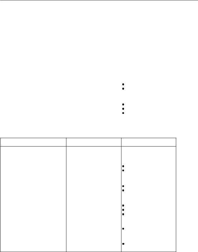
TROUBLESHOOTING USING LED AND OSD
1.Display
(1)OSD
Two kinds of error messages are displayed on the screen, and the power is turned off 10 sec later.
(2)LED
LED error is displayed continuously after the power is turned off.
2.Error types and check points
(1)OSD
On screen display |
Cause |
Check point |
|
|
|
ERROR MESSAGE CONDITION 1 |
Fan protector operated |
Fan |
|
|
|
|
|
Main/Digital PCB |
|
|
|
ERROR MESSAGE CONDITION 2 |
Temperature protector |
Ambient temperature of unit |
|
operated |
|
|
Main/Digital PCB |
|
|
|
|
|
|
Temp. sensor IC757 |
|
|
|
(2) LED
LED lamp display status |
Cause |
Check point |
Steady light (Red) |
Stand-by status |
-------------------- |
|
|
|
|
|
Continuous |
No power |
|
|
Flashes continuously (Red) |
Power supply protector |
Main/Digital PCB |
|
|
PDP panel |
||
|
operated |
||
|
|
||
|
|
|
|
1 time |
|
|
|
Flashes once every 4 sec. (Red) |
Fan protector operated |
Fan |
|
Main/Digital PCB |
|||
|
|
||
|
|
|
|
2 times |
|
Ambient temperature of unit |
|
Flashes twice every 5 sec. (Red) |
Temperature protector |
||
Temperature sensor IC757 |
|||
operated |
|||
|
Main/Digital PCB |
||
|
|
||
|
|
|
|
4 times |
Main/Digital circuit faulty |
Main/Digital PCB |
|
Flashes four times every 7 sec. |
|||
(Red) |
|
|
|
|
|
|
|
5 times |
Video circuit faulty |
Video PCB Assy |
|
Flashes five times every 8 sec. |
|||
(Red) |
|
|
--12--
MAIN POWER SELECTOR SWITCH ADJUSTMENT
Adjustment
Confirm the main voltage set switch is set to 230V. (W and E version)
Confirm the main voltage set switch is set to 110V. (U version)
Note:
230V covers input AC voltage from 200V till 260V, and 110V covers from 90V till 130V.
- 19 -
EXPLANATION OF LABELS
 Panel Label Information
|
|
|
|
|
MC106W36P4 |
|
|
|
Panel Part Number |
||
|
|
|
|
|
|
|
|
||||
|
|
|
|
No. ********** |
|
|
|
Panel Serial Number |
|||
|
|
|
|
|
|
|
|||||
|
Vbk : ***** V |
Vsus : ***** V |
|
|
|
Adjustment Voltage |
|||||
|
Ve |
: ***** V |
Vad : ***** V |
|
|
|
|||||
|
|
|
|
|
|||||||
|
*.*.* |
|
MADE IN JAPAN |
|
|
|
|
||||
|
|
|
|
|
|
|
|
|
|
|
|
|
|
|
|
|
|
|
|
|
|
|
|
|
|
|
|
|
Panel Production Date |
|
|
|
|
||
Panel Production Date |
|
|
|
|
|||||||
|
For Example---------1.8.2 |
|
|
|
|
||||||
|
|
|
|
|
|
|
|
|
|
|
|
|
|
1 |
|
|
|
8 |
2 |
|
|
|
|
|
Year |
|
|
Month |
|
|
|
|
|
||
|
9 : 1999 |
1 : JAN |
1 : Beginning of Month(01-10th) |
|
|
||||||
|
0 : 2000 |
2 : FEB |
2 : Middle of Month |
(11-20th) |
|
|
|||||
|
1 : 2001 |
3 : MAR |
3 : End of Month |
(21-31st) |
|
|
|||||
|
2 : 2002 |
|
|
|
|
|
|
|
|
||
|
|
|
|
|
9 : SEP |
|
|
|
|
|
|
|
|
|
|
|
0 : OCT |
|
|
|
|
|
|
|
|
|
|
|
N : NOV |
|
|
|
|
|
|
|
|
|
|
|
D : DEC |
|
|
|
|
|
|
Unit Serial Number |
|
|
|
|
|||||||
|
For Example----------- YA1450001 |
|
|
|
|
||||||
|
YA |
1 |
4 |
|
5 |
0001 * MID/AUG/2001 |
|
|
|
|
|
1 |
2 |
3 |
|
4 |
5 |
* YA Production Line |
|
|
|
|
|
|
1 Production Line No. |
|
4 Production Period (Day) |
||||||||
|
|
|
|
|
|
|
|
|
1st Month |
||
|
2 Production Year |
|
|
1 : BEG (1-10) |
|||||||
1 |
: 2001 |
|
|
|
|
2 : MID (11-20) |
|||||
2 |
: 2002 |
|
|
|
|
3 : END (21-30/31) |
|||||
|
|
|
|
|
|
|
|
|
2nd Month |
||
|
3 Production Month |
|
|
4 : BEG (1-10) |
|||||||
1 |
: JAN-FEB |
|
|
5 : MID (11-20) |
|||||||
2 |
: MAR-APR |
|
|
6 : END (21-30/31) |
|||||||
3 |
: MAY-JUN |
|
|
|
|
|
|||||
4 |
: JLY-AUG |
|
|
5 Serial Number |
|||||||
5 |
: SEP-OCT |
|
|
From 0001----- |
|||||||
6 |
: NOV-DEC |
|
|
|
|
|
|||||
- 20 -
REPLACEMENT PARTS AND REQUIRED ADJUSTMENT
Caution
To remove PCB, wait for 1 minute after power was turned off for electrolytic capacitors to discharge.
Preparation
Wide------------------ |
Auto |
Input------------------ |
White pattern |
Quick adjustment after PCB replacement
PCB |
Item |
VR |
Test Point |
Level |
|
|
|
|
|
|
|
|
Vsus |
R639 |
TPVsus |
Vsus ± 1V |
|
Power Supply PCB |
Vbk |
R513 |
TPVBK |
140V ± 5V |
|
Vda |
R528 |
P27 connector pin 2 |
75V ± 0.5V |
||
|
|||||
|
PFC |
R548 |
P4 connector pin 1 |
400V ± 1V |
|
Scan Drive PCB |
Vset |
R6940 |
TPSET |
224V ± 1V |
|
Vad |
R960 |
TPVAD |
VAD ± 1V |
||
|
|||||
Sustain Drive PCB |
Ve |
R6829 |
TPVE |
VE ± 1V |
|
Panel Drive Power PCB |
Vad |
R960 |
TPVAD |
VAD ± 1V |
|
|
Vsus |
R639 |
TPVsus |
Vsus ± 1V |
|
Panel Glass |
Vad |
R960 |
TPVAD |
VAD ± 1V |
|
|
Ve |
R6829 |
TPVE |
VE ± 1V |
- 21 -
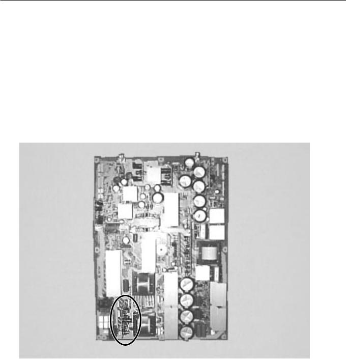
VR AND TEST POINT LOCATION
Adjustment VR Location
R6490/Vset R639/Vsus |
R528/Vda R513/Vbk R960/Vad |
R6556 R6524 R548/PFC R6829/Ve
S701
110V/230V Switch
Test Point Location
Label (Panel Information)
TPVscn TPVset |
TPVsus |
TPVbk |
TPPR1 TP15V |
TPSS1 |
TPSC1 |
R6524 TPSC2 TPVAD |
TPSS1 |
TPVe |
TPSS1 |
|
|
|
Label (Serial Number for Unit) |
|
- 22 -

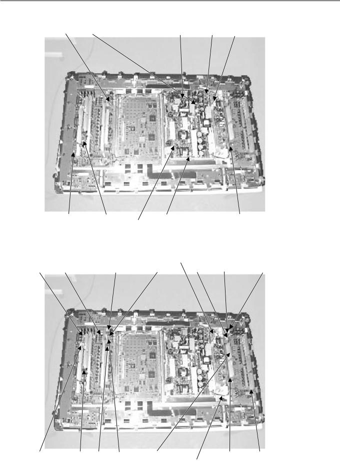
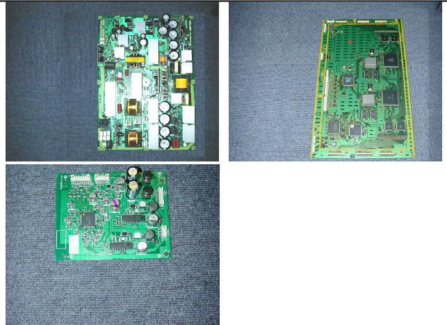
DISASSEMBLY PROCEDURES
1.Layout of Main PCB
1) Layout of Main PCB.
A: Main Digital PCB
B: Panel
Drive
Power
PCB
C: Data Drive (Upper
Left) PCB
D: Data Drive (Upper |
E: Data Drive (Upper |
Center) PCB |
Right) PCB |
PARTS LIST
Ref.no. |
Description |
PDS5003W-H PDS5003E-H PDS5003U-H PDS5003W-S PDS5003E-S PDS5003U-S |
|||||
Cabinet |
Case Front |
8112221009 |
|
|
8112484008 |
|
|
|
Case Rear |
8112437004 |
|
|
|
|
|
Electric |
Fan Motor |
8900280003 |
|
|
|
|
|
|
Optical Filter |
8113177008 |
|
|
|
|
|
|
Filter PCB Assy |
8112791007 |
|
8112792004 |
8112791007 |
|
8112523004 |
|
Audio Connection PCB |
8113113006 |
|
|
|
|
|
|
Audio Main PCB |
8113083002 |
|
|
|
|
|
|
Connection PCB Assy |
8113075007 |
|
|
|
|
|
|
DC/DC PCB Assy |
8113081008 |
|
|
|
|
|
|
I/O PCB Assy |
8113073003 |
|
|
|
|
|
|
Key Switch PCB Assy |
8113079005 |
|
|
|
|
|
|
LED/PHOTO PCB Assy |
8113077001 |
|
|
|
|
|
|
Main Digital PCB Assy |
8113339000 |
|
|
|
|
|
|
Video PCB Assy |
8113071009 |
|
|
|
|
|
|
PDP Unit |
S141010282 |
|
|
|
|
|
|
Power Cord VDE |
8112527002 |
|
----------- |
8112527002 |
|
----------- |
|
UL.CSA |
----------- |
----------- |
8112528009 |
----------- |
----------- |
8112528009 |
|
Remote Control Unit |
8108442005 |
|
|
8110867001 |
|
|
|
Panel Glass |
S141010107 |
|
|
|
|
|
|
Panel Drive Power PCB (P4) |
S141009958 |
|
|
|
|
|
|
Data Drive (Upper Left) PCB (C1) |
S141009965 |
|
|
|
|
|
|
Data Drive (Upper Center) PCB (C2) |
S141009972 |
|
|
|
|
|
|
Data Drive (Upper Right) PCB (C3) |
S141009989 |
|
|
|
|
|
|
Data Drive (Lower Right) PCB (C4) |
S141009996 |
|
|
|
|
|
|
Data Drive (Lower Center) PCB (C5) |
S141010008 |
|
|
|
|
|
|
Data Drive (Lower Left) PCB (C6) |
S141010015 |
|
|
|
|
|
|
Scan Drive Output (Upper) PCB (SU) |
S141010022 |
|
|
|
|
|
|
Scan Drive Output (Lower) PCB (SD) |
S141010039 |
|
|
|
|
|
|
Scan Drive PCB (SC) |
S141010046 |
|
|
|
|
|
|
Sustain Drive PCB (SS) |
S141010053 |
|
|
|
|
|
|
Saving Power (Upper/Lower Right) PCB (C7) |
S141010060 |
|
|
|
|
|
|
Saving Power (Upper/Lower Left) PCB (C8) |
S141010077 |
|
|
|
|
|
|
Power Supply PCB (P1) |
S141010084 |
|
|
|
|
|
|
Digital Process and Control PCB (D) |
S141010091 |
|
|
|
|
|
Packing Carton Top |
8112482004 |
|
|
|
|
|
|
|
Carton Bottom |
8112247009 |
|
|
|
|
|
|
Packing Joint-D |
8108655009 |
|
|
|
|
|
|
Packing Pad-Top |
8112248006 |
|
|
|
|
|
|
Packing Pad-Bottom |
8112249003 |
|
|
|
|
|
 : Same as left

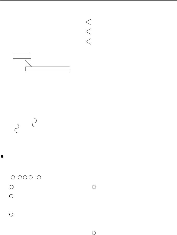
TRANSPORTATION AND HANDLING RESTRICTIONS
Transportation
Bad loading
Don't load the plasmavision on a truck as shown in the drawing.
Handling
Never topple. |
Never drop. |
Drop
Over 20 cm |
Floor |
- 60 -
3
Don't stack the plasmavision over two units high.
Example of good transportation and handling
Good loading
Load the plasmavision as shown above.
2
- 61 -
PARTS LIST
Ref.no. |
Description |
PDS5004W-S PDS5004E-S PDS5004U-S |
||
Cabinet |
Case Front |
8112484008 |
|
|
|
Case Rear |
8112437004 |
|
|
Electric |
Fan Motor |
8900280003 |
|
|
|
Optical Filter |
8112399005 |
|
|
|
Filter PCB Assy |
8112791007 |
|
8112792004 |
|
Audio Connection PCB |
8113113006 |
|
|
|
Audio Main PCB |
8113083002 |
|
|
|
Connection PCB Assy |
8113113006 |
|
|
|
DC/DC PCB Assy |
8113081008 |
|
|
|
I/O PCB Assy |
8113073003 |
|
|
|
Key Switch PCB Assy |
8113079005 |
|
|
|
LED/PHOTO PCB Assy |
8113077001 |
|
|
|
Main Digital PCB Assy |
8113339000 |
|
|
|
Video PCB Assy |
8113071009 |
|
|
|
PDP Unit |
S141010282 |
|
|
|
Power Cord VDE |
8112527002 |
|
----------- |
|
UL.CSA |
----------- |
----------- |
8112528009 |
|
Remote Control Unit |
8110867001 |
|
|
|
Panel Glass |
S141010107 |
|
|
|
Panel Drive Power PCB (P4) |
S141009958 |
|
|
|
Data Drive (Upper Left) PCB (C1) |
S141009965 |
|
|
|
Data Drive (Upper Center) PCB (C2) |
S141009972 |
|
|
|
Data Drive (Upper Right) PCB (C3) |
S141009989 |
|
|
|
Data Drive (Lower Right) PCB (C4) |
S141009996 |
|
|
|
Data Drive (Lower Center) PCB (C5) |
S141010008 |
|
|
|
Data Drive (Lower Left) PCB (C6) |
S141010015 |
|
|
|
Scan Drive Output (Upper) PCB (SU) |
S141010022 |
|
|
|
Scan Drive Output (Lower) PCB (SD) |
S141010039 |
|
|
|
Scan Drive PCB (SC) |
S141010046 |
|
|
|
Sustain Drive PCB (SS) |
S141010053 |
|
|
|
Saving Power (Upper/Lower Right) PCB (C7) |
S141010060 |
|
|
|
Saving Power (Upper/Lower Left) PCB (C8) |
S141010077 |
|
|
|
Power Supply PCB (P1) |
S141010084 |
|
|
|
Digital Process and Control PCB (D) |
S141010091 |
|
|
Packing Carton Top |
8112482004 |
|
|
|
|
Carton Bottom |
8112247009 |
|
|
|
Packing Joint-D |
8108655009 |
|
|
|
Packing Pad-Top |
8112248006 |
|
|
|
Packing Pad-Bottom |
8112249003 |
|
|
 : Same as left
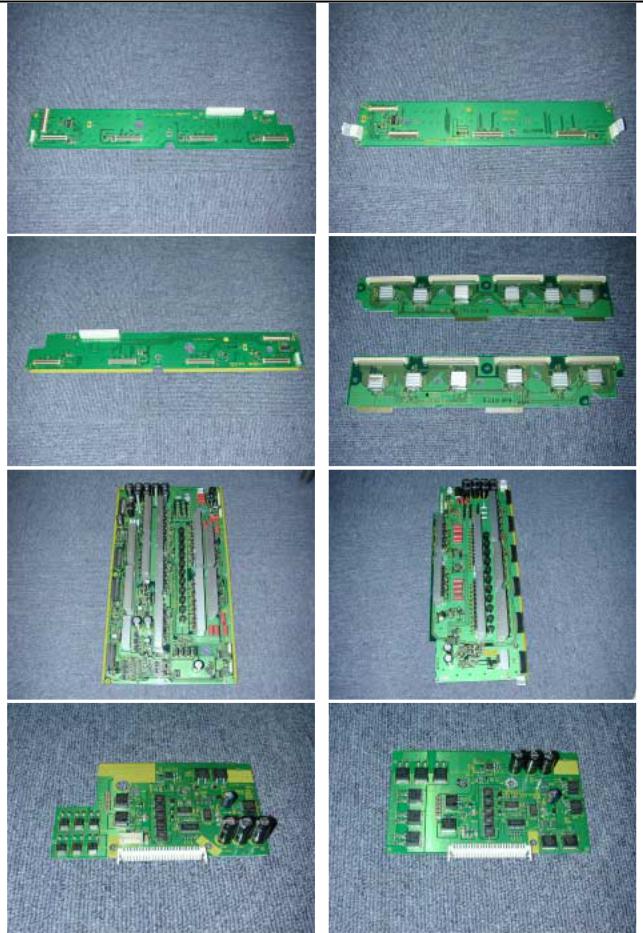
1. Layout of Main PCB. (2 of 3)
F: Data Drive (Lower |
G: Data Drive (Lower |
Right) PCB |
Center) PCB |
H: Data Drive (Lower
Left) PCB
K: Scan
Drive
PCB
M: Saving Power
(Upper/Lower Left)
I: Scan Drive Output (Upper)
J:Scan Drive Output (Lower)
L:Sustain Drive PCB
N: Saving Power
(Upper/Lower Right)
1. Layout of Main PCB (3 of 3)
O: Power |
P: Digital |
|
Supply |
Process |
|
PCB |
and |
|
Control |
||
|
Q: Audio Main PCB
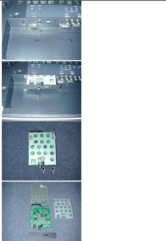
2. Removing the Video PCB
*The Video PCB can be removed without moving the Rear Case.
1) Remove the 2 circled screws.
2) Pull out the Video PCB Unit from the Plasmavision.
3) Remove 5 screws from the Video PCB Unit.
4) Remove the Video PCB Assy.
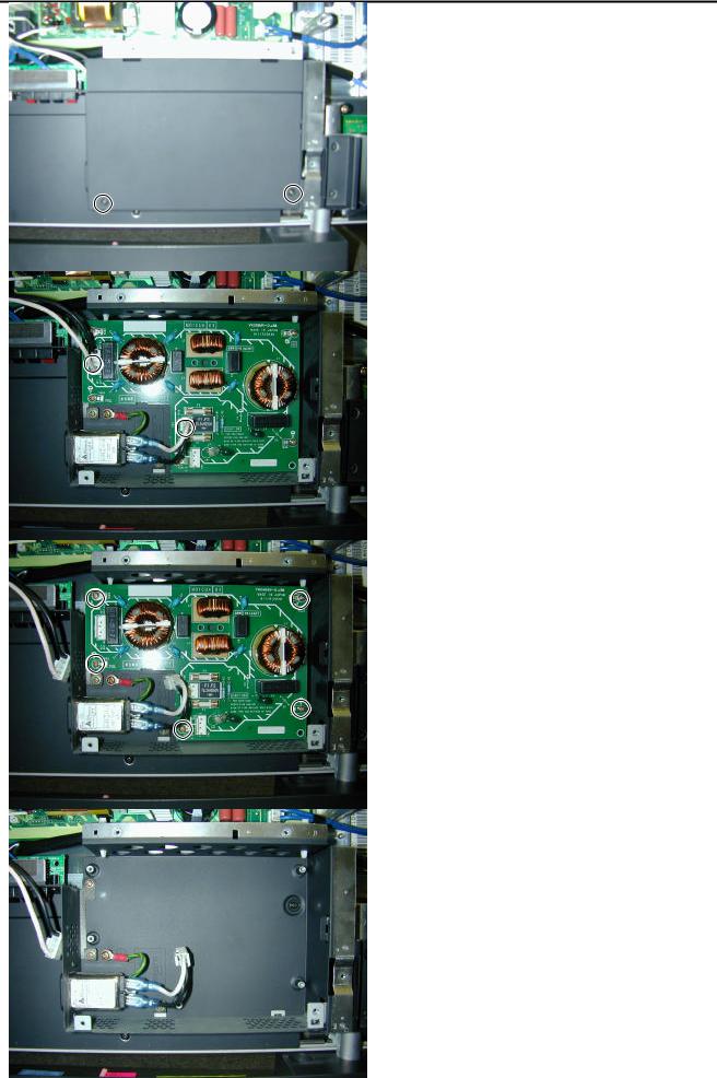
3. Removing the PFC PCB
1)Remove the Rear Case.
2)Remove the 2 screws and PFC cover.
3) Disconnect the circled connector.
4) Remove the 5 screws and PFC PCB.
* View after PFC PCB removed.
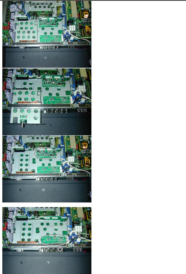
4. Removing the Main Digital PCB (1 of 3)
1) Remove the Rear Case.
2) Remove the Video Unit.
3) Remove the DC/DC PCB.
4) Remove the 3 screws and I/O PCB.
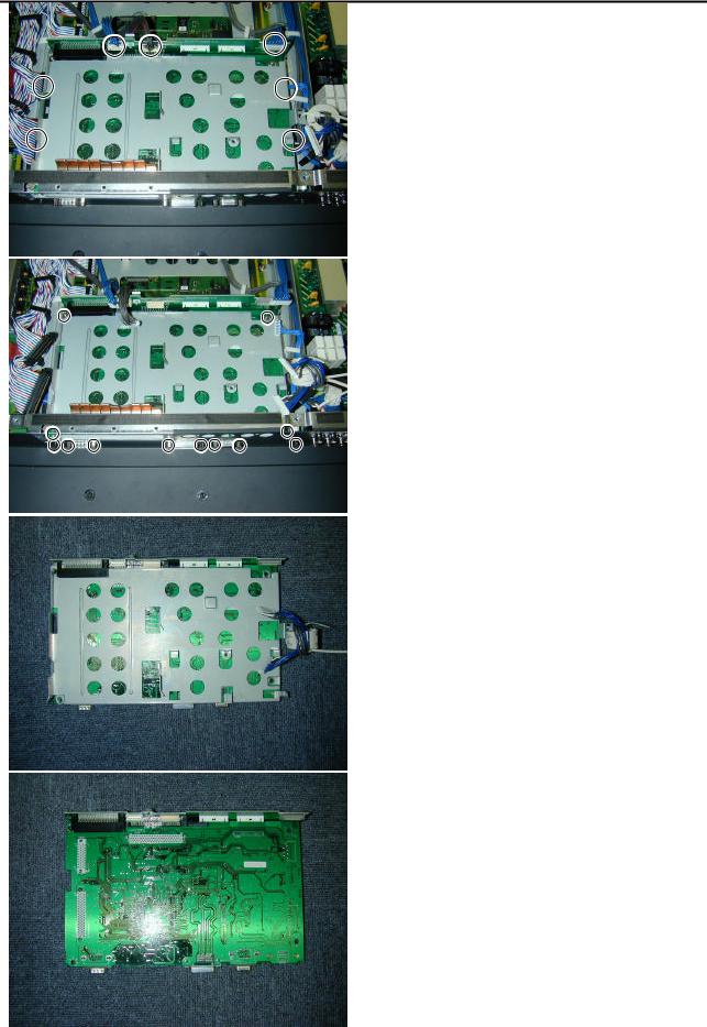
4. Removing the Main Digital PCB (2 of 3)
5) Disconnect the circled connector.
6) Remove the 12 screws and Main Digital Unit.
7) Remove the shield.
8) Turn over the Main Digital PCB.
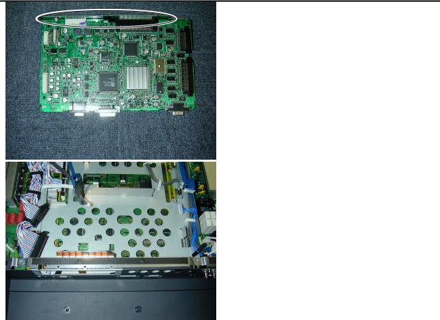
4. Removing the Main Digital PCB (3 of 3)
9) Remove the Connection PCB.
* View after Main Digital PCB removed.
 Loading...