


FFES3005LBD
Frigidaire FFES3005LBD, FFES3005LBE, FFES3005LWD, FFES3005LWE, FFES3015LBE Installation Guide
...
United States
iNSTALLATiON AND SERVICE MUST BE PERFORMED BY A
QUALiFiED iNSTALLER.
iMPORTANT: SAVE FOR LOCAL ELECTRICAL iNSPECTOR'S USE.
READ AND SAVE THESE iNSTRUCTiONS FOR FUTURE REFERENCE.
FOR YOUR SAFETY: Do not store or use gasoline or other
flammable vapors and liquids in the vicinity of this or any other appliance.
Canada
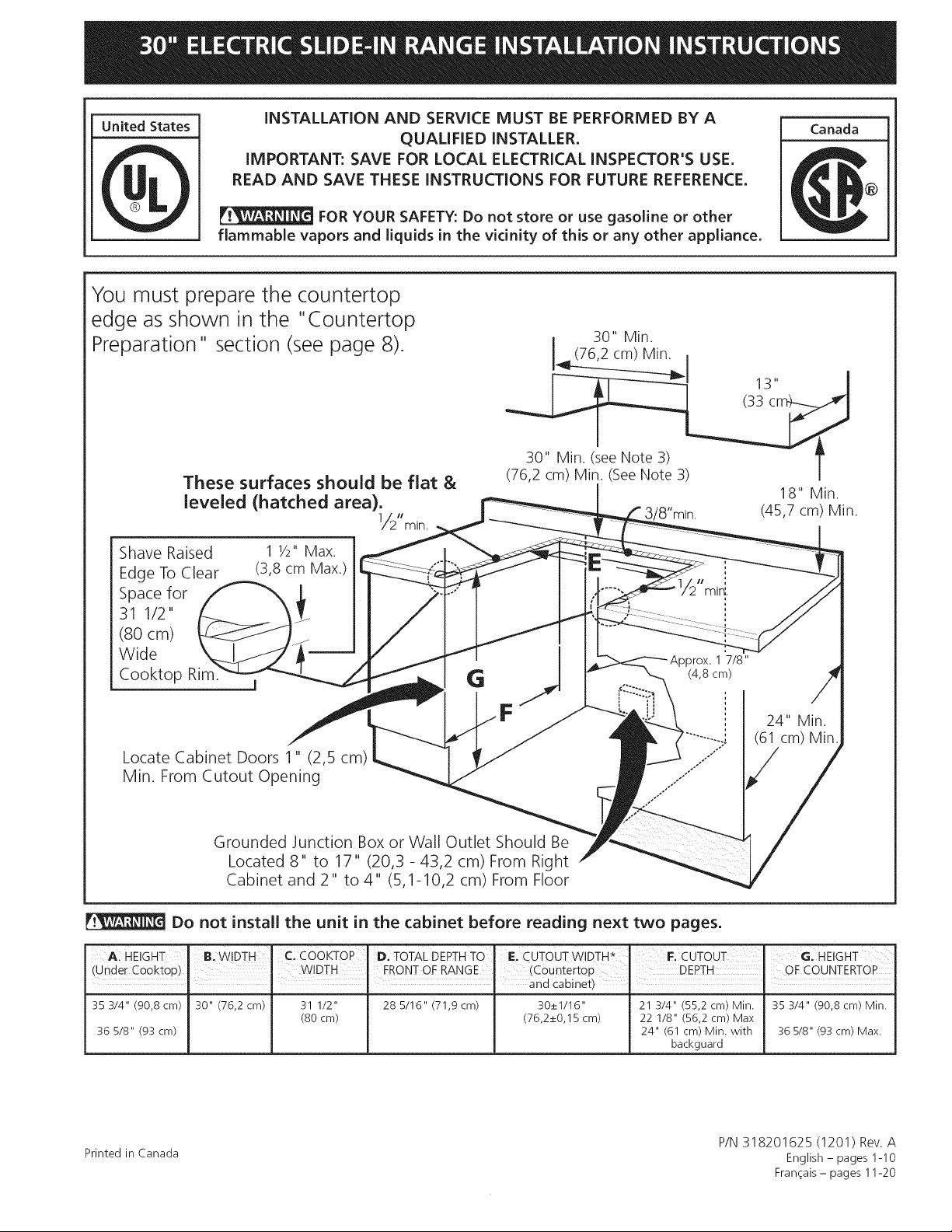
You must prepare the countertop
edge as shown in the "Countertop
Preparation" section (see page 8).
These surfaces should be flat &
leveled (hatched area).
1/2'/mJn,
30" Min.
] (76,2 cm) Min. ,
30" Min. (see Note 3) T
(76,2 cm) Min. (See Note 3) |
18" Min.
/8"min. (45,7 cm) Min.
Shave Raised
Edge To Clear
Space for
31 1/2"
(80 cm)
Wide
Cooktop Rim.
1 1/2"Max.
(3,8 cm Max.)
Locate Cabinet Doors 1" (2,5 cm)
Min. From Cutout Opening
Grounded Junction Box or Wall Outlet Should Be
Located 8" to 17" (20,3 - 43,2 cm) From Right
Cabinet and 2" to 4" (5,1-10,2 cm) From Floor
_rox. 1 7/8"
(4,8 cm)
24" Min.
(61 cm) Min
Do not install the unit in the cabinet before reading next two pages.
A HEIGHT
(Unde_ Cooktop)
35 3/4" (90,8 cm)
36 5/8" (93 cm)
B. WIDTH "cIco0KToP D. TOTAL DEPTH TO E. CuToUTWlDTH*' I=: CUTOUT G. HEIGHT
WIDTH FRONT OF RANGE (Countertop DEPTH OF COUNTERTOP
" and cabinet)
30" (76,2 cm) 31 1/2" 285/16" (71,9 cm) 30_+1/16" 21 3/4" (55,2 cm) Min. 353/4" (90,8 cm) Min.
(80 cm) (76,2_+0,15 cm) 22 1/8" (56,2 cm) Max
24" (61 cm) Min. with 36 5/8" (93 cm) Max.
backguard
Printed in Canada
P/N 318201625 (1201) Rev. A
English- pages 1-10
Fran_ais - pages 11-20
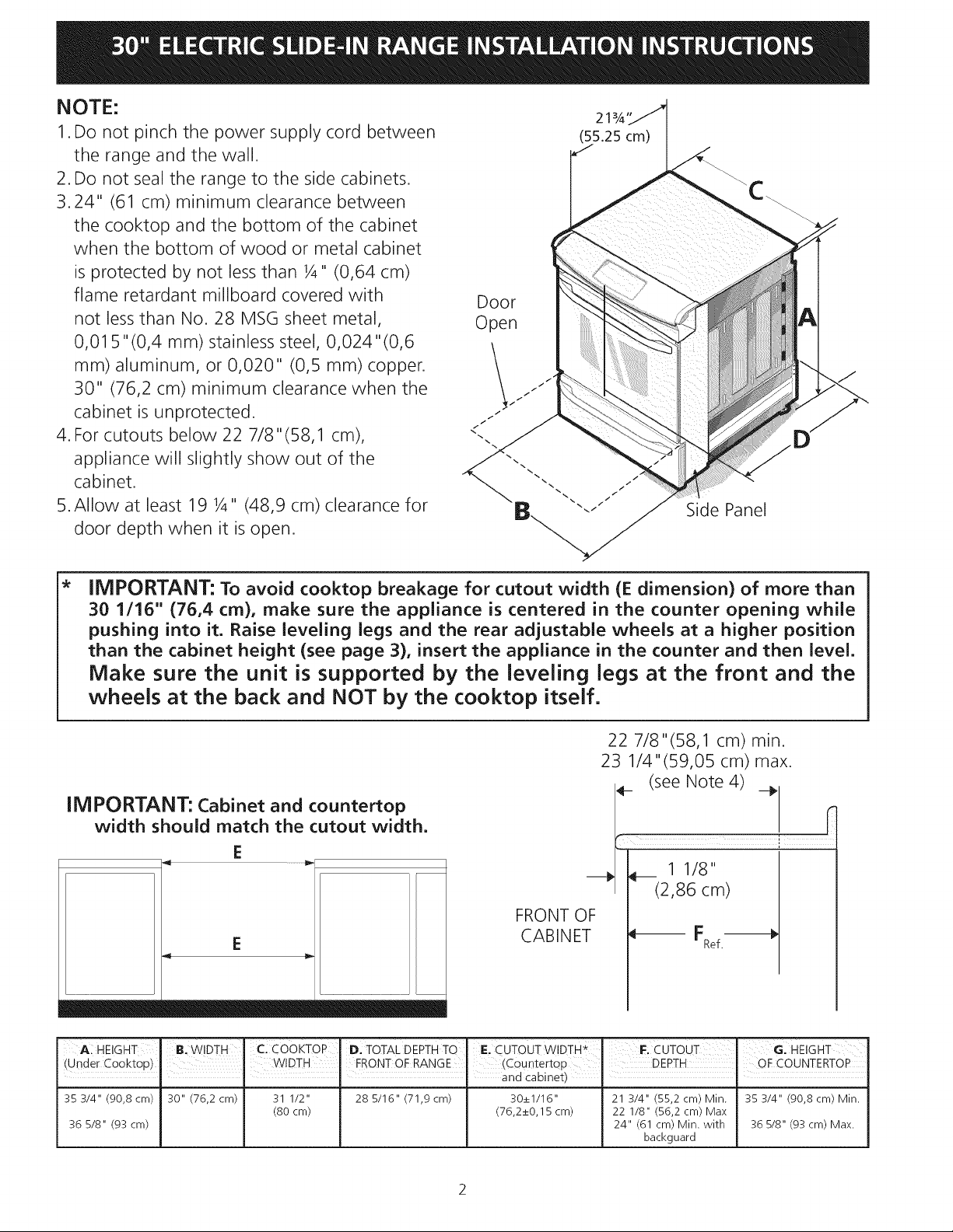
NOTE:
1. Do not pinch the power supply cord between
the range and the wall.
2. Do not seal the range to the side cabinets.
_3.24" (61 cm) minimum clearance between
the cooktop and the bottom of the cabinet
when the bottom of wood or metal cabinet
is protected by not less than ¼" (0,64 cm)
flame retardant millboard covered with
not less than No. 28 MSG sheet metal,
0,015 "(0,4 mm) stainless steel, 0,024"(0,6
mm) aluminum, or 0,020" (0,5 mm) copper.
_30" (76,2 cm) minimum clearance when the
cabinet is unprotected.
4. For cutouts below 22 7/8"(58,1 cm),
appliance will slightly show out of the
cabinet.
5.Allow at least 19 ¼" (48,9 cm) clearance for
door depth when it is open.
Door
Open
21
(55.25 cm)
Side Panel
IMPORTANT: To avoid cooktop breakage for cutout width (E dimension) of more than
30 1/16" (76,4 cm), make sure the appliance is centered in the counter opening while
pushing into it. Raise leveling legs and the rear adjustable wheels at a higher position
than the cabinet height (see page 3), insert the appliance in the counter and then level.
Make sure the unit is supported by the leveling legs at the front and the
wheels at the back and NOT by the cooktop itself.
IMPORTANT: Cabinet and countertop
width should match the cutout width.
E
E
22 7/8"(58,1 cm) min.
23 1/4"(59,05 cm) max.
F (see Note 4) __
_/_ 1 1/8
! (2,86 cm)
FRONT OF
CABINET _-- FRef.-_
A:HEIGHT B.W!DTH C Co0KToP . D. TOTAL DEPTHTO IE. CuToUTW!DTH* FiCUTOU T G. HEIGHT
(Unde[ Cooktop) WIDTH FRONTOF RANGE (Countertop DEPTH " OF COUNTERTOP
' ' I I and cabinet) I
35 3/4" (90,8 cm) 30" (76,2 cm) 31 1/2"
(80 cm)
36 5/8" (93 cm)
28 5/16" (71,9 cm) 30_+1/16" 21 3/4" (55,2 cm) Min. 35 3/4" (90,8 cm) Min.
(76,2_+0,15 cm) 22 1/8" (56,2 cm) Max
24" (61 cm) Min. with 36 5/8" (93 cm) Max.
backguard
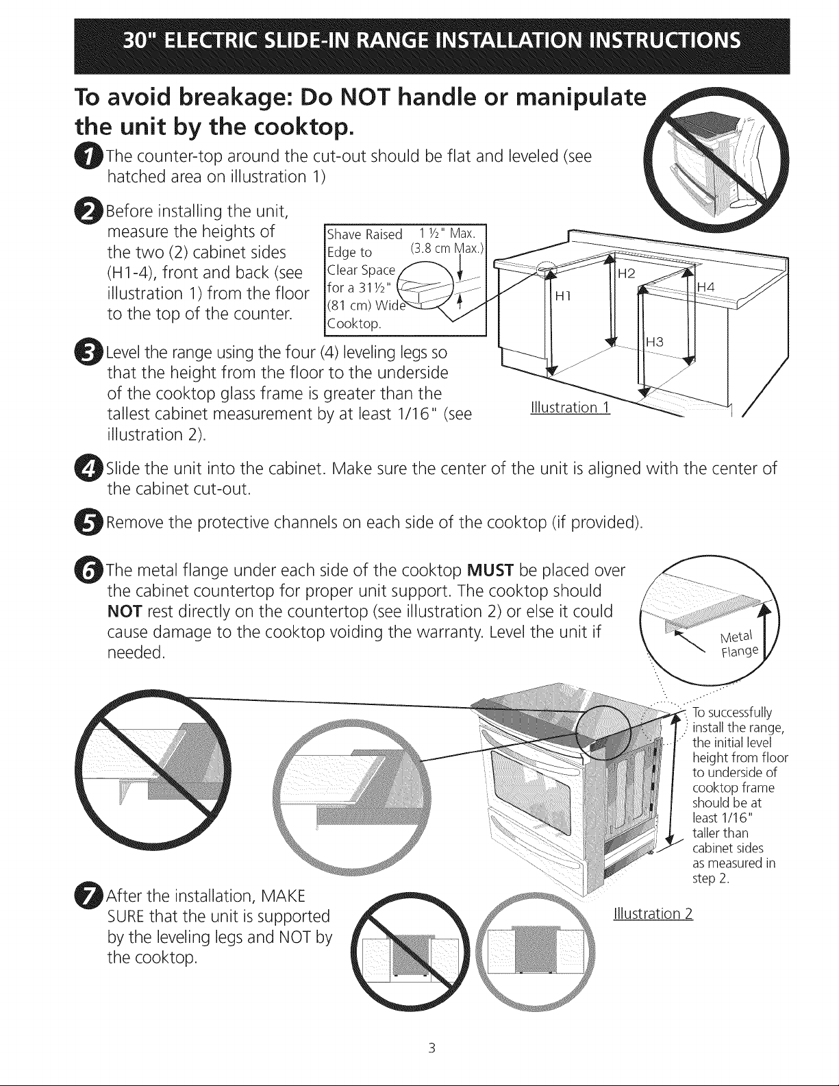
To avoid breakage: Do NOT handle or manipulate
the unit by the cooktop.
_Thecounter-top around the cut-out should be flat and leveled (see
hatched area on illustration 1)
_Before installing the unit,
measure the heights of
the two (2) cabinet sides
(H1-4), front and back (see
illustration 1) from the floor
to the top of the counter.
Shave Raised
Edge to
Clear Space
for a 311/2"
(81 cm) Wk
Cooktop.
_Levelthe range using the four (4)leveling legs so
that the height from the floor to the underside
of the cooktop glass frame is greater than the
tallest cabinet measurement by at least 1/16" (see
illustration 2).
Illustration 1
bSlidethe unit into the cabinet. Make sure the center of the unit is aligned with the center of
the cabinet cut-out.
_Removethe protective channels on each side of the cooktop (if provided).
bThemetal flange under each side of the cooktop MUST be placed over
the cabinet countertop for proper unit support. The cooktop should
NOT rest directly on the countertop (see illustration 2) or else it could
cause damage to the cooktop voiding the warranty. Level the unit if
needed.
_After the installation, MAKE
SUREthat the unit is supported
by the leveling legs and NOT by
the cooktop.
Tosuccessfully
install the range,
•" the initial level
height from floor
to underside of
cooktop frame
should be at
least 1/16"
taller than
cabinet sides
asmeasured in
step 2.
Illustration 2
3
important Notes to the Installer
1. Read all instructions contained in these installation
instructions before installing range.
2. Remove all packing material from the oven
compartments before connecting the electrical supply
to the range.
3. Observe all governing codes and ordinances.
4. Be sure to leave these instructions with the consumer.
important Note to the Consumer
Keep these instructions with your Owner's Guide for the
local electrical inspector's use and future reference.
IMPORTANT SAFETY
INSTRUCTION
_Co]d temperatures can damage the
electronic control. When using the appliance for the first
time, or when the appliance has not been used for an
extended period of time, be certain the unit has been
in temperatures above 32% (0°C) for at least 3 hours
before turning on the power to the appliance.
• Be sure your range is installed and grounded
properly by a qualified installer or service
technician.
This range must be electrically grounded in
accordance with local codes or, in their absence,
with the National Electrical Code ANSI/NFPA No.
70--latest edition in United States or with CSA
Standard C22.1, Canadian Electrical Code, Part I in
Canada.
The installation of appliances designed for
manufactured (mobile) home installation must conform
with Manufactured Home Construction and Safety
Standard, title 24CFR, part 3280 [Formerly the Federal
Standard for Mobile Home Construction and Safety,
title 24, HUD (part 280)] or when such standard
is not applicable, the Standard for Manufactured
Home Installation 1982 (Manufactured Home Sites,
Tip Over Hazard
• Achild or adult can tip the range
and be killed.
• Verify the anti-tip device has been
installed to floor or wall.
Ensure the anti-tip device is re-engaged to floor
or wall when the range is moved.
Do not operate the range without the anti-tip
device in place and engaged.
Failure to follow these instructions can result in
death or serious burns to children and adults.
To check if the anti-tip bracket is
installed properly, use both arms
and grasp the rear edge of range
back. Carefully attempt to tilt range
forward. When properly installed, the
range should not tilt forward.
Communities and Setups), ANSI Z225.1/NFPA 501A-
latest edition, or with local codes in United States and
with CAN/CSA-Z240 MH in Canada.
• Make sure the wall coverings around the range
can withstand the heat generated by the range.
• Before installing the range in an area covered
with linoleum or any other synthetic floor
covering, make sure the floor covering can
withstand heat at least 90°F (32.2°C) above room
temperature without shrinking, warping or
discoloring. Do not install the range over carpeting
unless you place an insulating pad or sheet of 1/4"
(0.64 cm) thick plywood between the range and
_ Never leave children alone or
unattended in the area where an appliance is in
use. As children grow, teach them the proper, safe use
of all appliances. Never leave the oven door open when
t_unattended.
Stepping, leaning or sitting on the
door or drawer of this range can result in serious
injuries and can also cause damage to the range.
Do not store items of interest to children in
the cabinets above the range. Children could be
seriously burned climbing on the range to reach items.
To eliminate the risk of burns or fire by reaching
over heated surface units, cabinet storage
space above the surface unit should be avoided.
If cabinet storage is to be provided the risk can
be reduce by installing a range hood that project
horizontally a minimum of 5 inches beyond the bottom
of the cabinet.
Do not use the oven as a storage space. This
creates a potentially hazardous situation.
Never use your range for warming or heating the
room. Prolonged use of the range without adequate
ventilation can be dangerous.
Do not store or use gasoline or other flammable
vapors and liquids near this or any other
appliance. Explosions or fires could result.
Reset all controls to the "off" position after using
a programmable timing operation.
FOR MODELS WITH SELF-CLEAN FEATURE:
Remove oven racks, broiler pan, food and other
utensils before self-cleaning the oven. Wipe up
excess spillage. Follow the precleaning instructions in
the Owner's Guide.
Serial Plate Location
You will find the model and
serial number printed on the
serial plate. The serial plate is
located as shown.
Remember to record the
serial number for future
reference.
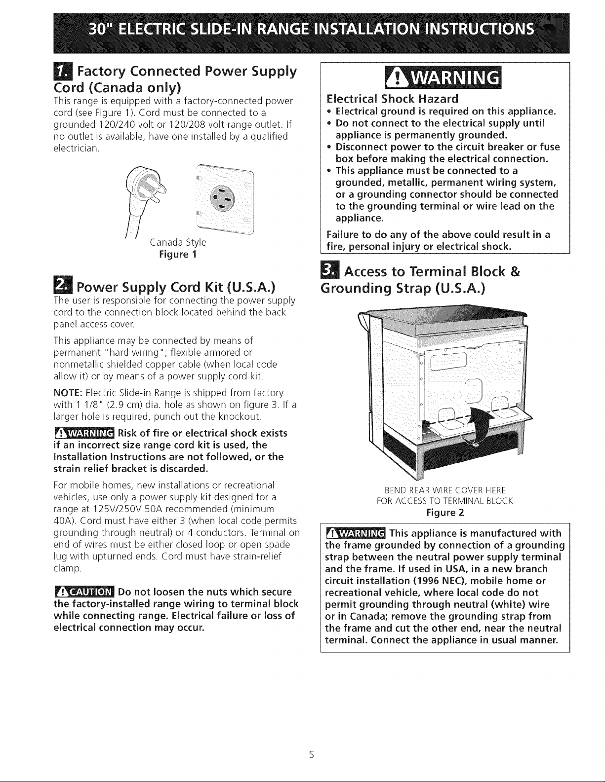
Factory Connected Power Supply
Cord (Canada only)
This range is equipped with a factory-connected power
cord (see Figure 1). Cord must be connected to a
grounded 120/240 volt or 120/208 volt range outlet. If
no outlet is available, have one installed by a qualified
electrician.
Canada Style
Figure 1
Power Supply Cord Kit (U.S.A.)
The user is responsible for connecting the power supply
cord to the connection block located behind the back
panel access cover.
This appliance may be connected by means of
permanent "hard wiring"; flexible armored or
nonmetallic shielded copper cable (when local code
allow it) or by means of a power supply cord kit.
NOTE: Electric Slide-in Range is shipped from factory
with 1 1/8" (2.9 cm) dia. hole as shown on figure 3. If a
larger hole is required, punch out the knockout.
Risk of fire or electrical shock exists
if an incorrect size range cord kit is used, the
Installation Instructions are not followed, or the
strain relief bracket is discarded,
For mobile homes, new installations or recreational
vehicles, use only a power supply kit designed for a
range at 125V/250V 50A recommended (minimum
40A). Cord must have either 3 (when local code permits
grounding through neutral) or 4 conductors. Terminal on
end of wires must be either closed loop or open spade
lug with upturned ends. Cord must have strain-relief
clamp.
Do not loosen the nuts which secure
the factory-installed range wiring to terminal block
while connecting range, Electrical failure or loss of
electrical connection may occur,
Electrical Shock Hazard
o Electrical ground is required on this appliance,
Do not connect to the electrical supply until
appliance is permanently grounded.
Disconnect power to the circuit breaker or fuse
box before making the electrical connection,
This appliance must be connected to a
grounded, metallic, permanent wiring system,
or a grounding connector should be connected
to the grounding terminal or wire lead on the
appliance,
Failure to do any of the above could result in a
fire, personal injury or electrical shock,
Access to Terminal Block &
Grounding Strap (U.S.A.)
BEND REARWIRE COVER HERE
FORACCESS TO TERMINAL BLOCK
Figure 2
This appliance is manufactured with
the frame grounded by connection of a grounding
strap between the neutral power supply terminal
and the frame, If used in USA, in a new branch
circuit installation (1996 NEC), mobile home or
recreational vehicle, where local code do not
permit grounding through neutral (white) wire
or in Canada; remove the grounding strap from
the frame and cut the other end, near the neutral
terminal, Connect the appliance in usual manner,
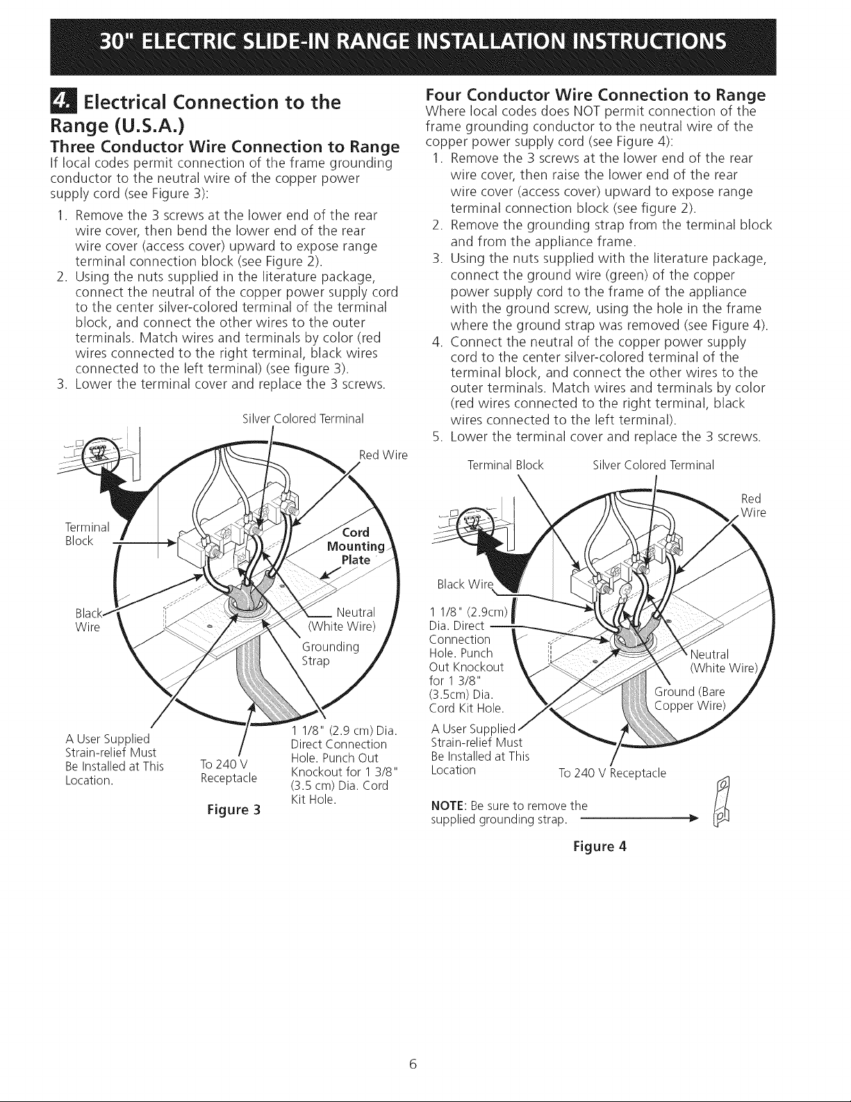
Electrical Connection to the
Range (U.S.A.)
Three Conductor Wire Connection to Range
If local codes permit connection of the frame grounding
conductor to the neutral wire of the copper power
supply cord (see Figure 3):
1. Remove the 3 screws at the lower end of the rear
wire cover, then bend the lower end of the rear
wire cover (accesscover) upward to expose range
terminal connection block (see Figure 2).
2. Using the nuts supplied in the literature package,
connect the neutral of the copper power supply cord
to the center silver-colored terminal of the terminal
block, and connect the other wires to the outer
terminals. Match wires and terminals by color (red
wires connected to the right terminal, black wires
connected to the left terminal) (see figure 3).
3. Lower the terminal cover and replace the 3 screws.
Silver Colored Terminal
Red Wire
Four Conductor Wire Connection to Range
Where local codes does NOT permit connection of the
frame grounding conductor to the neutral wire of the
copper power supply cord (see Figure 4):
1. Remove the 3 screws at the lower end of the rear
wire cover, then raise the lower end of the rear
wire cover (accesscover) upward to expose range
terminal connection block (see figure 2).
2. Remove the grounding strap from the terminal block
and from the appliance frame.
3. Using the nuts supplied with the literature package,
connect the ground wire (green) of the copper
power supply cord to the frame of the appliance
with the ground screw, using the hole in the frame
where the ground strap was removed (see Figure 4).
4. Connect the neutral of the copper power supply
cord to the center silver-colored terminal of the
terminal block, and connect the other wires to the
outer terminals. Match wires and terminals by color
(red wires connected to the right terminal, black
wires connected to the left terminal).
5. Lower the terminal cover and replace the 3 screws.
Terminal Block Silver Colored Terminal
Terminal
Block
Red
W ire
Wire
A User Supplied
Strain-relief Must
Be Installed at This
Location.
To240 V
Receptacle
Figure 3
1 1/8" (2.9 cm) Dia.
Direct Connection
Hole. Punch Out
Knockout for 1 3/8"
(3.5 cm) Dia. Cord
Kit Hole.
BlackWire
1 1/8" (2.9cm)t
Dia.Direct
!
Connection
Hole.Punch
Out Knockout
for 13/8"
(3.5cm)Dia.
Cord Kit Hole.
A User Supplied
Strain-relief Must
Be Installed at This
Location
To 240 V Receptacle
NOTE: Besure to remove the
supplied grounding strap.
Figure 4
 Loading...