

Page 1

Worcester Controls
WCAIM2030
(Part 16474)
Miser Ball Valves
Installation, Operation and Maintenance Instructions
CAUTION: Flowserve recommends that all product which must be
stored prior to installation be stored indoors, in an environment
suitable for human occupancy. Do not store product in areas where
exposure to relative humidity above 85%, acid or alkali fumes,
radiation above normal background, ultraviolet light, or
temperatures above 120°F or below 40°F may occur. Do not store
within 50 feet of any source of ozone.
A. INSTALLATION
1. Miser valves may be installed for flow or vacuum in either
direction. Use care to exclude pipe sealants from the valve
cavity. Valves with upstream relief hole in ball (V3 option) are
one-way valves.
Miser Diverter Valves (D) may be installed using the bottom port
as the inlet port. The flow can then be diverted to either one of the
two side outlet ports.
Miser Three-Way Valves (T) may be installed using any of the
ports as inlet or outlet ports. The source can be selected from
either of two sources to be directed toward one outlet. It can also
be selected from one source to one outlet and then, by rotating
the valve, use that outlet as an inlet and use the third port as the
new outlet. The three-way valve does not have separate body
seals. This function is incorporated into the three-way seat.
Therefore, more care than normal must be taken to not damage
the back face of this seat upon disassembly and reassembly.
Note that for CL44 valves, the maximum pressure rating is 300 psi
per Chlorine Institute. The Chorine Institute recommends that the
relief hole in the ball be upstream, toward the pressure source. An
arrow stamped on the body or on a metal tag welded to the body
indicates flow path.
2. Weld End Valves (TE, SW, BW, SWO, XBO):
NOTE: Prior to welding or brazing, THOROUGHLY CLEAN ALL
JOINT SURFACES to prevent contamination. Worcester brass
valves are of leaded forging brass. Brazing can not be
successfully accomplished unless a white flux is used.
Valves with “PG”, “RG”, “XG”, “AG”, and “GG” seat and body seal
combinations and V67 option code are compatible with welding
temperatures. Therefore, these valves are weld-as-is and do not
have to be disassembled to be welded in the line. These valves
will have a red welding tag attached. If these valves are
disassembled, the graphite-coated stainless steel gasket body
seals and the seat back seals (used with “A” or “G” seats only)
must be replaced. When welding these valves, the ball must be
open to prevent adhesion of weld spatter to the ball. Use STICK or
MIG welding, and allow valve and joint to cool to the touch
between passes.
Valves with XBO pipe ends can be welded in line as assembled.
For all other weld, braze or solder valves:
a. Tack weld valve in place.
b. With valve open, remove three body bolts, loosen fourth and
swing out body.
NOTE: AF44 and FZ44 fire valves can not be swung out.
Remove fourth bolt and spread pipe ends to clear centering
ring, if any (rings are no longer used with revision R4 and
later fire valves are fire valves with “G” seats.).
Close valve, remove ball, seats, body seals or one-piece
(three-way) seat/body seals.
Return body to its original position and temporarily secure it
with two body bolts diagonally opposite each other.
1
/
4" - 2" 4, 44 — Includes CL, H, MP, PT, S, W, W2 and WK44 Series
1
/
2" - 2" D, T and FZ series
1
/
4" -
3
/
8" AF Series
1
/
4" - 1
1
/
2" 59 — Includes PT, W and W2 Series
Page 2

Flow Control Division
Worcester Controls
2 Miser Ball Valves WCAIM2030
c. Weld valve in line (when gas welding or brazing do not play
flame on valve body.)
d. Allow valve to cool, reassemble valve. Install new body seals,
if they were shipped separately from the valve. Temporary
Buna body seals, if found in the valve as received, are not to
be reused. If coated stainless steel “S” gasket body seals are
used (Code M or G), the wide flange of the “S” gasket must
face the valve body. See View A-A detail on page 5.
e. Tighten and torque body bolts evenly and diagonally opposite
each other, alternating in a criss-cross pattern. Use torque
figures below:
Carbon Steel Bolts Stainless Steel and Alloy 20 Bolts
Bolt Dia. In-Lbs Ft-Lbs Bolt Dia. In-Lbs Ft-Lbs
1
/
4" 96-120 8-10
1
/
4" 72-94 6-8
5
/
16" 156-204 13-17
5
/
16" 120-144 10-12
3
/
8" 216-264 18-22
3
/
8" 192-216 16-18
7
/
16" 480-540 40-45
7
/
16" 336-384 28-32
1
/
2" 720-780 60-65
1
/
2" 504-552 42-46
Note: Stainless steel bolts and nuts are generally used in all
three-piece valves with stainless steel bodies, FZ valves and
valves with “G” seats.
CAUTION: The fluoropolymer and UHMWPE body seals
(codes T and U), and the coated stainless steel gaskets
(codes M and G) make excellent seals. However, some
points of caution in their use need emphasizing.
3. a. No fluoropolymer or UHMWPE part (except a seat) or seat
back seal is reusable. Coated stainless steel gaskets are also
not reusable and cannot be used in stainless bodies with cast
surfaces or serrations in body seal area. These include R12,
R14, R15, R17, R20, R22 or current R1 and R3 Revision level
44 and 59 valves. Upon disassembly of the valve, these seals
or gaskets should be discarded and replaced with new parts.
b. Care must be taken to avoid scratching the fluoropolymer or
UHMWPE seals, or the coating of the stainless steel gaskets
during installation. Light lubrication of these seals can help to
prevent damage.
c. Care must also be taken when handling a graphite thrust
bearing, stem seal, or seat back seal. These parts can be
easily damaged by squeezing the O.D. of the seal. Parts are to
be handled on the flat surfaces rather than the O.D.
d. The ball used in valves with “A” and “G” (filled metal) seats is
round to special tolerances. To ensure proper contact with the
seat, do not drop, dent or scratch the ball during handling.
These balls also have an anti-galling coating. DO NOT use
uncoated balls with filled metal seats.
e. Standard WK44 and CL44 valves are furnished with one-
piece seat/body seals. More care than normal must be taken
to not damage the back face of these seats during
disassembly and reassembly.
f. WK44 valves and repair kits have been assembled, cleaned,
and packaged for ultra high purity systems, and caution
should be used to maintain the integrity of the valve parts.
g. WK44 valves are assembled with no lubrication.
B. OPERATION
1. The operation consists of turning the handle and/or stem
1
/
4 turn
clockwise to close and
1
/
4 turn counter-clockwise to open. When
the handle and/or stem flats are in line with the pipeline, the valve
is open. These valves may also be automated.
2. These valves will provide bubble-tight shut-off when used in
accordance with Worcester’s published pressure/temperature
chart. Valves with “G” seats meet the leakage rates of ANSI
B16.104 Class VI.
3. The diverter valve will allow no leakage through the closed outlet
port when used as described with the bottom port as the inlet. If
other inlet ports are needed, the three-way valve is to be used
which also does not allow leakage through the closed port.
The porting one (V1) style valve is operated by turning the handle
one quarter-turn to change selection of sources. With this style of
valve the flow is never shut-off and some mixing of the media is
possible. This valve is easily automated with a pneumatic or
electric actuator.
The porting two (V2) style valve is operated by turning the handle
one-half turn to direct the flow from one side to the other. With
this style valve, the flow is shut-off in the 90° position. (There is
no stop in this position.) This valve may be automated with an
electric actuator only.
4. It is not good practice to leave a ball valve partly open (throttling
operation) without knowledge of the pressure drop and flow at
that position.
5. As shipped from the factory, all valves (except CL44, WK44,
oxygen prepared (V20, V33 or prefix code “X”), and valves with
V38 or V6 options) contain a silicone-based lubricant. This is for
break-in purposes, and may be removed if it is objectionable for a
particular application by disassembling and solvent washing.
Lacquer thinner will remove the lubricant. “A” or “G” (filled metal)
seated valves should not be operated without a break-in lubricant.
6. Media which can solidify, crystallize or polymerize should not be
allowed to stand in ball valve cavities.
7. Torque Requirements – Operating torque requirements will vary
depending on the length of time between cycles, line pressure,
type of valve seats, and the media in the system. For a detailed
analysis of valve torque requirements, see Worcester’s Actuator
Sizing Manual.
Page 3

C. MAINTENANCE
Tighten retaining nut if seepage is noted at stem.
CAUTION: For maximum stem seal life, proper stem adjustment
procedure must be followed.
Excessive tightening causes higher torque and shorter stem seal life.
For CL44 valves only, immediately after the first frost is detected
around the stem, tighten the retaining or self-locking nut, as stated
below, to adjust the compression of the stem seals.
For Valves with two stem nuts and a lockwasher
(with or without handle):
1. Tighten retaining nut (lower nut) until Belleville washers are flat,
the nut will “bottom”.
2. Back off retaining nut
1
/
6 turn.
3. Tighten handle nut securely to lock retaining nut in place. (On
some automated valves, two retaining nuts are used with a
lockwasher in between. Hold the bottom nut securely with a
wrench while tightening the top nut to lock the 2 nuts in place.)
For Valves with self-locking stem nut (and four Belleville washers):
1. Tighten self-locking stem nut until Belleville washers are flat, the
nut will “bottom”.
2. Back off nut
1
/
3 turn.
CAUTION: The self-locking stem nut is difficult to tighten, and
must fully flatten Belleville washers before backing off.
D. REBUILDING
a WARNING: BALL VALVES CAN TRAP PRESSURIZED FLUIDS IN
BALL CAVITY WHEN CLOSED
Special handling and cleaning procedures are necessary for oxygen
and vacuum service valves. Refer to industry practices when
overhauling these units.
If the valve has been used to control hazardous media, it must be
decontaminated before disassembly. It is recommended that the
following steps are taken for safe removal and disassembly:
• Relieve the line pressure. Operate the valve prior to attempting
removal from line.
• Place valve in half-open position and flush the line to remove any
hazardous material from valve.
• For CL44 valves, refer to Chlorine Institute Pamphlet 6 procedure
for flushing and drying, and for additional information on
precautions and cleaning.
• All persons involved in the removal and disassembly of the valve
should wear the proper protective clothing such as face shield,
gloves, apron, etc.
1. A standard repair kit may be ordered for these valves, consisting
of seats and body seals or one-piece (three-way) seat/body seals,
two or four Belleville washers, seat back seals (used with “A” or
“G” seat only), stem seal(s), and thrust bearing(s). specify the
material of seats and body seals, size, series and R number
(revision number) of valve or for non-standard valve, the “P”, “T”,
“C”, or similar number, as found on the valve body, stop plate,
handle, valve nameplate or on the actuator bracket nameplate. If
valve body is stainless steel or Alloy 20, place a “6” after valve
size in repair kit ordering code.
To Order: Valve Size/Series/RK 44 or 59/Material/Revision No., or
P, T, C, etc., Number
Examples:
1" 6 FZ RK 44 PM RO
1" RK 59 PM R16
1
/
2" RK 44 RT TO914
CAUTION: If the seats and seals installed differ from those
removed, the valve nameplate or stop must be replaced or
remarked to indicate the altered materials and ratings, or valve
tagged to so indicate.
2. To replace seats and seals:
a. Place valve in open position, remove three body nuts and
bolts, loosen fourth, swing out center section from between
pipe ends with valve open. Some AF44 and FZ44 fire valves
require the removal of all four bolts and spreading the pipe
ends to clear the pipe end centering rings, if any (valves with
“G” seats or revision R4 and later fire valves do not use
centering rings).
b. With valve in closed position, remove old seats, body seals or
one-piece (three-way) seat/body seals, seat back seals (if
any), and ball.
c. Remove handle nut, lockwasher, separate handle and stop or
one-piece handle and stop (if manual valve). (This step is not
applicable to valves with self-locking stem nut.)
d. Using handle or a wrench to prevent stem from turning,
remove retaining or self-locking stem nut, Belleville
washers, and follower from stem. Remove the stem through
body cavity.
e. Remove thrust bearing(s) from body or stem; stem seal(s),
and stem seal protector (if any), from recess in top of body.
f. Clean all sealing surfaces of valve including the ball.
Flow Control Division
Worcester Controls
WCAIM2030 Miser Ball Valves 3
Page 4

Flow Control Division
Worcester Controls
4 Miser Ball Valves WCAIM2030
NOTE: The ball and the surfaces against which the seats and
seals are installed should be undamaged, clean and free of pit
marks and scratches. Light marring from the action of the ball
against the seats is normal and will not affect the operation of
the valve. Flaws which can be seen but barely detected with
fingertips are acceptable. The stem and body surfaces that the
thrust bearing(s) and stem seal(s) contact must be
undamaged, clean, and free of pit marks and scratches.
g. Lightly lubricate the ball, seats, body seals, stem seal(s), stem
seal protector and seat back seals (if any), and thrust
bearing(s) with a lubricant compatible with the media being
handled, except for valves with V20, V33 or V38 options,
which are assembled dry. White petroleum jelly is a good
general-purpose lubricant.
For valve repair kits with “A” or “G” seats, the filled metal
seats will be lubricated at the factory. If they are not, they
should be lubricated as noted in Paragraph B.5. and also as
stated above. Do not operate a newly rebuilt valve using filled
metal seats without lubricants. The seat back seals will be
pre-assembled to the seat backs.
For CL44, and oxygen prepared (prefix code “X”) valves only,
lightly lubricate the ball, seats/body seals, stem seal and
thrust bearing with a PTFE-based lubricant as Fluorolube S-30
or equivalent.
h. For stem area rebuilding, refer to exploded view, stem build
illustrations and stem component color chart on the following
pages that pertain to the type valve being rebuilt.
Order of Assembly:
Place new thrust bearing(s) on stem and insert assembly
through body cavity. Place new stem seal(s), stem seal
protector (if any), and the follower in position. PEEK thrust
bearing and stem seal protectors are placed outside of seals
and bearings. The seals/bearings must contact the body.
NOTE: For valves having graphite stem seal(s), care must be
taken when installing the graphite parts because they are
easily damaged by squeezing the O.D. of the seals. Handle
gently by holding seal(s) on flat surfaces rather than on the
O.D. If resistance is encountered when installing seal(s) over
the stem, use follower to gently push the stem seal(s) down.
Stem seals, stem seal protectors and thrust bearings that are
the same size and color are interchangeable.
i Place two new Belleville washers in position with the larger
diameter sides touching each other.
For those valves with single self-locking stem nut, place four
new Belleville washers in position (two pairs of washers with
larger diameter sides touching each other).
j. Place retaining or self-locking stem nut on stem and using
handle or a wrench to prevent rotation, tighten nut to make
snug and firm. Follow Section C, Maintenance, for proper
stem adjustment.
k. Replace separate stop and handle or one-piece handle and stop
(if manual valve), lockwasher and handle nut on stem. (This
step is not applicable to valves with self-locking stem nut.)
l. With valve in closed position (stem flats going across
pipeline), replace ball (see note below), one-piece (three-way)
seat/body seal (if used), or seats and seat back seals (if any).
With valve in open position, carefully insert new body seals
and place center section between pipe ends. For AF44 and
FZ44 fire valves, insert centering rings, if any, into pipe ends
before installing center section of valve. For valves with
coated stainless steel “S”gaskets, install with wide flange
facing body (see view A-A on page 5). For valves with “A” or
“G” seats, before putting the center section back between the
pipe ends make sure that the seat back seal is located on the
seat correctly. If it is not, it could be damaged or cause the
valve to leak.
NOTE: For diverter and three-way valves, install ball as
follows:
V1(90° valves)– with handle and/or stem flats in line with
body main axis, viewed from bolt head side (normally
upstream) one ball port is to the right, one is down, and one
is on opposite end of valve.
V2(180° valves)- Using some convention as V1, one ball port
is down and the other is on opposite end of valve.
Valves with a pressure relief hole in the ball (V3 option and
chlorine valves) must be assembled and installed with the
hole upstream when the valve is closed, to insure that cavity
relief is upstream. Any valve with a relief hole will have an
arrow on the body pointing downstream. This arrow is
tamped on the body or on a metal tag welded to the body.
Replace and tighten body bolts and nuts per torque figures
and method found in Section A.2.e.
CAUTION: Do not scratch body seals when replacing valve
body.
When ordering parts, please provide the part name and the
following information as found on the valve body, stop plate,
handle, valve nameplate, or mounting bracket nameplate:
1. Valve Size, Style and Revision Number – Example:
1
/
2"
4466T SE RO STEM
2. Valve Size, Style and Five-Character Code, known as a
“P”, “T”, “C”, or similar number, the designation for a
non-standard product. – Example:
3
/
4" 4446RT SW T0726
BALL
3. Porting (if a diverter or three-way valve) must also be
specified when ordering these parts. Example: 1" D4466 T
SE V1 R8 BALL
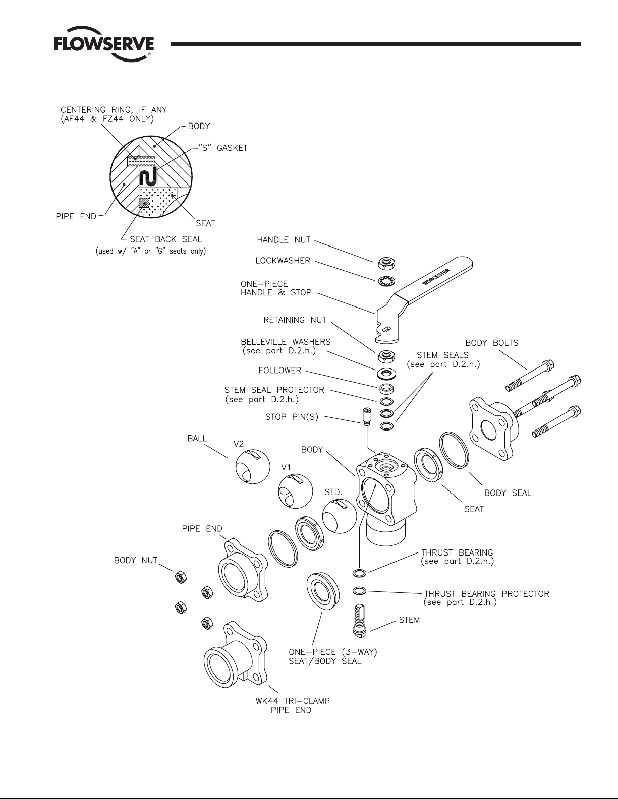
The terminology shown in the exploded view Parts Listing
on next page is standard.
Page 5
Flow Control Division
Worcester Controls
WCAIM2030 Miser Ball Valves 5
View A-A
1
1
/4" – 2" Size Top-Mount Valves Shown
Page 6
Flow Control Division
Worcester Controls
6 Miser Ball Valves WCAIM2030
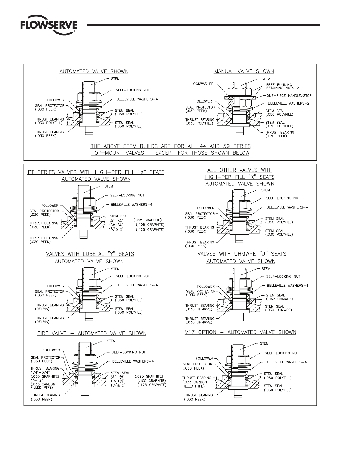
Top-Mount Valve Stem Builds
NOTE: Manual valve stem build compoents such as stem seal(s), thrust bearings, and seal protector are the same as automated valves. For
colors of various stem components, see color chart on page 8. For fire valves and valves with V17 option used in oxygen service, use polyfill
stem seal and thrst bearing protectors in place of PEEK material.
Page 7
Flow Control Division
Worcester Controls
WCAIM2030 Miser Ball Valves 7
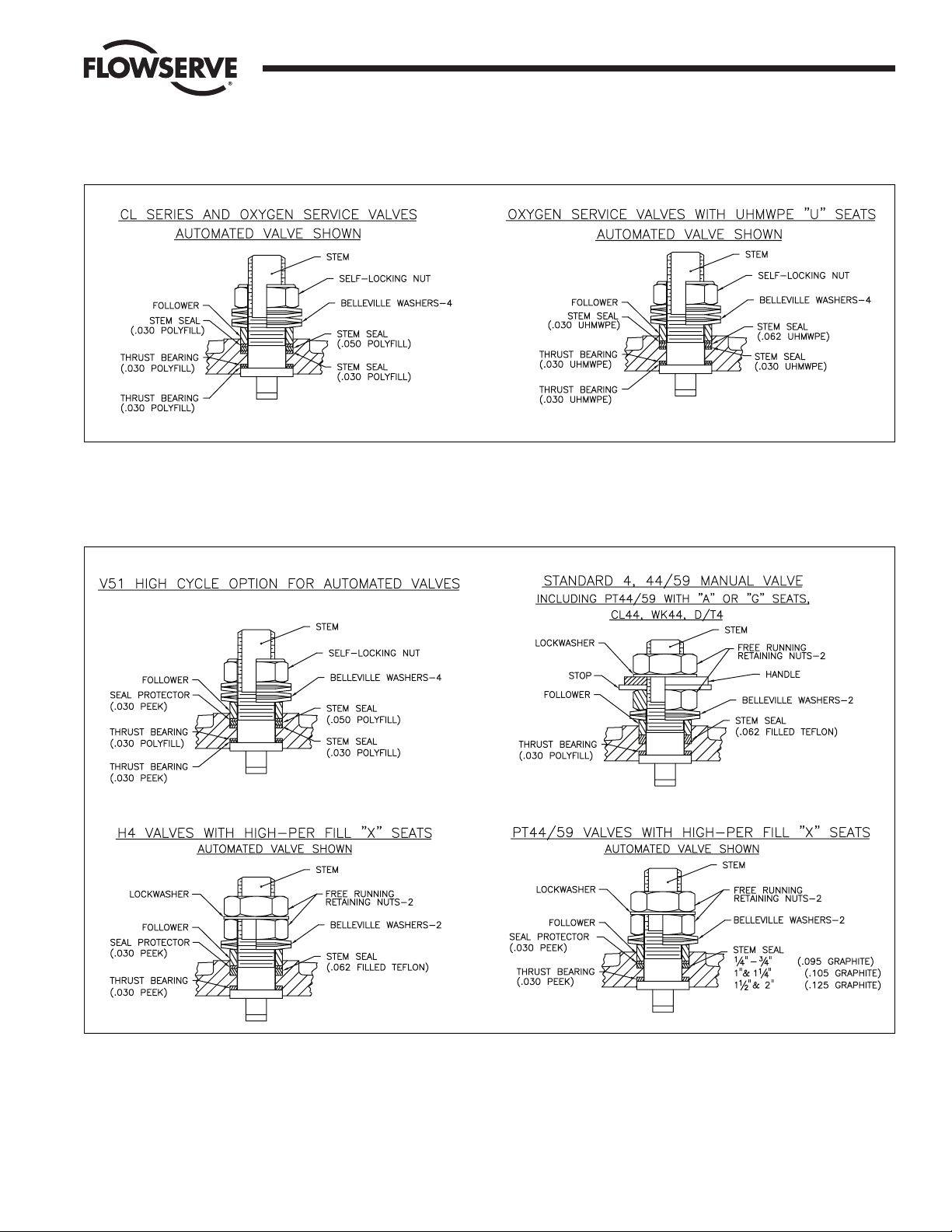
Top-Mount Valve Stem Builds, continued
All Non-Top-Mount Valve Stem Builds
NOTE: Stem build components such as stem seal(s), thrust bearings, and seal protector (if used) are the same for manual and automated valves.
For colors of various stem components, see color chart on page 8.
Page 8

Flow Control Division
Worcester Controls
Flowserve Corporation has established industry leadership in the design and manufacture of its products. When properly selected, this Flowserve product is designed to perform its intended function
safely during its useful life. However, the purchaser or user of Flowserve products should be aware that Flowserve products might be used in numerous applications under a wide variety of industrial
service conditions. Although Flowserve can (and often does) provide general guidelines, it cannot provide specific data and warnings for all possible applications. The purchaser/user must therefore
assume the ultimate responsibility for the proper sizing and selection, installation, operation, and maintenance of Flowserve products. The purchaser/user should read and understand the Installation
Operation Maintenance (IOM) instructions included with the product, and train its employees and contractors in the safe use of Flowserve products in connection with the specific application.
While the information and specifications contained in this literature are believed to be accurate, they are supplied for informative purposes only and should not be considered certified or as a guarantee of
satisfactory results by reliance thereon. Nothing contained herein is to be construed as a warranty or guarantee, express or implied, regarding any matter with respect to this product. Because Flowserve
is continually improving and upgrading its product design, the specifications, dimensions and information contained herein are subject to change without notice. Should any question arise concerning
these provisions, the purchaser/user should contact Flowserve Corporation at any one of its worldwide operations or offices.
For more information about Flowserve Corporation, contact www.flowserve.com or call USA 1-800-225-6989.
FLOWSERVE CORPORATION
FLOW CONTROL DIVISION
1978 Foreman Drive
Cookeville, Tennessee 38501 USA
Phone: 931 432 4021
Facsimile: 931 432 3105
www.flowserve.com
© 2003 Flowserve Corporation, Irving, Texas, USA. Flowserve and Worcester Controls are registered trademarks of Flowserve Corporation. WCAIM2030 10/03 Printed in USA
All Non-Top-Mount Valve Stem Builds, continued
NOTE: Stem build components such as stem seal(s), thrust bearing(s), and seal protector (if used) are the same for manual and
automated valves. For colors of various stem components, see color chart below.
 Loading...